EP2750864B1 - Verfahren zum verbinden von transfer- oder laminierfolienbahnen - Google Patents
Verfahren zum verbinden von transfer- oder laminierfolienbahnen Download PDFInfo
- Publication number
- EP2750864B1 EP2750864B1 EP12745449.4A EP12745449A EP2750864B1 EP 2750864 B1 EP2750864 B1 EP 2750864B1 EP 12745449 A EP12745449 A EP 12745449A EP 2750864 B1 EP2750864 B1 EP 2750864B1
- Authority
- EP
- European Patent Office
- Prior art keywords
- film
- film web
- layer
- welding
- seam
- Prior art date
- Legal status (The legal status is an assumption and is not a legal conclusion. Google has not performed a legal analysis and makes no representation as to the accuracy of the status listed.)
- Not-in-force
Links
- 238000000034 method Methods 0.000 title claims description 35
- 238000012546 transfer Methods 0.000 title claims description 25
- 238000010030 laminating Methods 0.000 title description 12
- 238000005304 joining Methods 0.000 title description 5
- 239000010410 layer Substances 0.000 claims description 97
- 238000003466 welding Methods 0.000 claims description 60
- 238000010521 absorption reaction Methods 0.000 claims description 10
- 230000008569 process Effects 0.000 claims description 10
- 229920001169 thermoplastic Polymers 0.000 claims description 10
- 239000012790 adhesive layer Substances 0.000 claims description 8
- 239000004416 thermosoftening plastic Substances 0.000 claims description 8
- 238000010438 heat treatment Methods 0.000 claims description 5
- 210000001503 joint Anatomy 0.000 claims description 4
- 230000015572 biosynthetic process Effects 0.000 claims description 2
- 239000010408 film Substances 0.000 description 127
- 239000011888 foil Substances 0.000 description 19
- 239000002390 adhesive tape Substances 0.000 description 15
- 239000000463 material Substances 0.000 description 9
- 229920000139 polyethylene terephthalate Polymers 0.000 description 9
- 239000005020 polyethylene terephthalate Substances 0.000 description 9
- 230000008901 benefit Effects 0.000 description 8
- 238000004049 embossing Methods 0.000 description 8
- 239000000853 adhesive Substances 0.000 description 6
- 230000001070 adhesive effect Effects 0.000 description 6
- 239000004922 lacquer Substances 0.000 description 5
- 238000012545 processing Methods 0.000 description 5
- 230000009466 transformation Effects 0.000 description 4
- 238000011109 contamination Methods 0.000 description 3
- 230000000694 effects Effects 0.000 description 3
- 238000004519 manufacturing process Methods 0.000 description 3
- 238000002844 melting Methods 0.000 description 3
- 230000008018 melting Effects 0.000 description 3
- 238000001465 metallisation Methods 0.000 description 3
- 230000003287 optical effect Effects 0.000 description 3
- 239000000049 pigment Substances 0.000 description 3
- 230000005855 radiation Effects 0.000 description 3
- 238000012360 testing method Methods 0.000 description 3
- CBQBIPRPIHIKPW-RXMQYKEDSA-N (2r)-2-chloro-4-methylpentanoic acid Chemical compound CC(C)C[C@@H](Cl)C(O)=O CBQBIPRPIHIKPW-RXMQYKEDSA-N 0.000 description 2
- VYZAMTAEIAYCRO-UHFFFAOYSA-N Chromium Chemical compound [Cr] VYZAMTAEIAYCRO-UHFFFAOYSA-N 0.000 description 2
- 230000009471 action Effects 0.000 description 2
- 230000004913 activation Effects 0.000 description 2
- 229910052782 aluminium Inorganic materials 0.000 description 2
- XAGFODPZIPBFFR-UHFFFAOYSA-N aluminium Chemical compound [Al] XAGFODPZIPBFFR-UHFFFAOYSA-N 0.000 description 2
- 239000004973 liquid crystal related substance Substances 0.000 description 2
- 229910052751 metal Inorganic materials 0.000 description 2
- 239000002184 metal Substances 0.000 description 2
- 239000005022 packaging material Substances 0.000 description 2
- 238000002360 preparation method Methods 0.000 description 2
- 238000000926 separation method Methods 0.000 description 2
- 239000012815 thermoplastic material Substances 0.000 description 2
- 229920002799 BoPET Polymers 0.000 description 1
- RYGMFSIKBFXOCR-UHFFFAOYSA-N Copper Chemical compound [Cu] RYGMFSIKBFXOCR-UHFFFAOYSA-N 0.000 description 1
- 239000004831 Hot glue Substances 0.000 description 1
- 229910000831 Steel Inorganic materials 0.000 description 1
- 229910010413 TiO 2 Inorganic materials 0.000 description 1
- RTAQQCXQSZGOHL-UHFFFAOYSA-N Titanium Chemical compound [Ti] RTAQQCXQSZGOHL-UHFFFAOYSA-N 0.000 description 1
- 238000002679 ablation Methods 0.000 description 1
- 238000004026 adhesive bonding Methods 0.000 description 1
- 230000000903 blocking effect Effects 0.000 description 1
- 230000008859 change Effects 0.000 description 1
- 239000003795 chemical substances by application Substances 0.000 description 1
- 229910052804 chromium Inorganic materials 0.000 description 1
- 239000011651 chromium Substances 0.000 description 1
- 229920001940 conductive polymer Polymers 0.000 description 1
- 229910052802 copper Inorganic materials 0.000 description 1
- 239000010949 copper Substances 0.000 description 1
- 238000005520 cutting process Methods 0.000 description 1
- 230000006378 damage Effects 0.000 description 1
- 238000005034 decoration Methods 0.000 description 1
- 238000013461 design Methods 0.000 description 1
- 238000001035 drying Methods 0.000 description 1
- 238000005516 engineering process Methods 0.000 description 1
- 238000002474 experimental method Methods 0.000 description 1
- 239000000835 fiber Substances 0.000 description 1
- 238000002372 labelling Methods 0.000 description 1
- 238000003475 lamination Methods 0.000 description 1
- 239000002346 layers by function Substances 0.000 description 1
- 238000011068 loading method Methods 0.000 description 1
- 230000010534 mechanism of action Effects 0.000 description 1
- 150000002739 metals Chemical class 0.000 description 1
- 238000002156 mixing Methods 0.000 description 1
- 230000004048 modification Effects 0.000 description 1
- 238000012986 modification Methods 0.000 description 1
- 238000004806 packaging method and process Methods 0.000 description 1
- 238000012858 packaging process Methods 0.000 description 1
- 229920000728 polyester Polymers 0.000 description 1
- -1 polyethylene terephthalate Polymers 0.000 description 1
- 239000011241 protective layer Substances 0.000 description 1
- 230000010076 replication Effects 0.000 description 1
- 238000005096 rolling process Methods 0.000 description 1
- 239000007858 starting material Substances 0.000 description 1
- 239000010959 steel Substances 0.000 description 1
- 239000000758 substrate Substances 0.000 description 1
- 229920001187 thermosetting polymer Polymers 0.000 description 1
- 230000008719 thickening Effects 0.000 description 1
- 239000010409 thin film Substances 0.000 description 1
- 239000010936 titanium Substances 0.000 description 1
- 229910052719 titanium Inorganic materials 0.000 description 1
- 238000002604 ultrasonography Methods 0.000 description 1
- 238000004804 winding Methods 0.000 description 1
Images


Classifications
-
- B—PERFORMING OPERATIONS; TRANSPORTING
- B29—WORKING OF PLASTICS; WORKING OF SUBSTANCES IN A PLASTIC STATE IN GENERAL
- B29C—SHAPING OR JOINING OF PLASTICS; SHAPING OF MATERIAL IN A PLASTIC STATE, NOT OTHERWISE PROVIDED FOR; AFTER-TREATMENT OF THE SHAPED PRODUCTS, e.g. REPAIRING
- B29C65/00—Joining or sealing of preformed parts, e.g. welding of plastics materials; Apparatus therefor
- B29C65/02—Joining or sealing of preformed parts, e.g. welding of plastics materials; Apparatus therefor by heating, with or without pressure
- B29C65/06—Joining or sealing of preformed parts, e.g. welding of plastics materials; Apparatus therefor by heating, with or without pressure using friction, e.g. spin welding
- B29C65/069—Joining or sealing of preformed parts, e.g. welding of plastics materials; Apparatus therefor by heating, with or without pressure using friction, e.g. spin welding the welding tool cooperating with specially formed features of at least one of the parts to be joined, e.g. cooperating with holes or ribs of at least one of the parts to be joined
-
- B—PERFORMING OPERATIONS; TRANSPORTING
- B29—WORKING OF PLASTICS; WORKING OF SUBSTANCES IN A PLASTIC STATE IN GENERAL
- B29C—SHAPING OR JOINING OF PLASTICS; SHAPING OF MATERIAL IN A PLASTIC STATE, NOT OTHERWISE PROVIDED FOR; AFTER-TREATMENT OF THE SHAPED PRODUCTS, e.g. REPAIRING
- B29C65/00—Joining or sealing of preformed parts, e.g. welding of plastics materials; Apparatus therefor
- B29C65/02—Joining or sealing of preformed parts, e.g. welding of plastics materials; Apparatus therefor by heating, with or without pressure
- B29C65/08—Joining or sealing of preformed parts, e.g. welding of plastics materials; Apparatus therefor by heating, with or without pressure using ultrasonic vibrations
- B29C65/083—Joining or sealing of preformed parts, e.g. welding of plastics materials; Apparatus therefor by heating, with or without pressure using ultrasonic vibrations using a rotary sonotrode or a rotary anvil
- B29C65/087—Joining or sealing of preformed parts, e.g. welding of plastics materials; Apparatus therefor by heating, with or without pressure using ultrasonic vibrations using a rotary sonotrode or a rotary anvil using both a rotary sonotrode and a rotary anvil
-
- B—PERFORMING OPERATIONS; TRANSPORTING
- B29—WORKING OF PLASTICS; WORKING OF SUBSTANCES IN A PLASTIC STATE IN GENERAL
- B29C—SHAPING OR JOINING OF PLASTICS; SHAPING OF MATERIAL IN A PLASTIC STATE, NOT OTHERWISE PROVIDED FOR; AFTER-TREATMENT OF THE SHAPED PRODUCTS, e.g. REPAIRING
- B29C65/00—Joining or sealing of preformed parts, e.g. welding of plastics materials; Apparatus therefor
- B29C65/02—Joining or sealing of preformed parts, e.g. welding of plastics materials; Apparatus therefor by heating, with or without pressure
- B29C65/14—Joining or sealing of preformed parts, e.g. welding of plastics materials; Apparatus therefor by heating, with or without pressure using wave energy, i.e. electromagnetic radiation, or particle radiation
- B29C65/16—Laser beams
- B29C65/1629—Laser beams characterised by the way of heating the interface
- B29C65/1635—Laser beams characterised by the way of heating the interface at least passing through one of the parts to be joined, i.e. laser transmission welding
-
- B—PERFORMING OPERATIONS; TRANSPORTING
- B29—WORKING OF PLASTICS; WORKING OF SUBSTANCES IN A PLASTIC STATE IN GENERAL
- B29C—SHAPING OR JOINING OF PLASTICS; SHAPING OF MATERIAL IN A PLASTIC STATE, NOT OTHERWISE PROVIDED FOR; AFTER-TREATMENT OF THE SHAPED PRODUCTS, e.g. REPAIRING
- B29C65/00—Joining or sealing of preformed parts, e.g. welding of plastics materials; Apparatus therefor
- B29C65/02—Joining or sealing of preformed parts, e.g. welding of plastics materials; Apparatus therefor by heating, with or without pressure
- B29C65/14—Joining or sealing of preformed parts, e.g. welding of plastics materials; Apparatus therefor by heating, with or without pressure using wave energy, i.e. electromagnetic radiation, or particle radiation
- B29C65/16—Laser beams
- B29C65/1629—Laser beams characterised by the way of heating the interface
- B29C65/1654—Laser beams characterised by the way of heating the interface scanning at least one of the parts to be joined
-
- B—PERFORMING OPERATIONS; TRANSPORTING
- B29—WORKING OF PLASTICS; WORKING OF SUBSTANCES IN A PLASTIC STATE IN GENERAL
- B29C—SHAPING OR JOINING OF PLASTICS; SHAPING OF MATERIAL IN A PLASTIC STATE, NOT OTHERWISE PROVIDED FOR; AFTER-TREATMENT OF THE SHAPED PRODUCTS, e.g. REPAIRING
- B29C65/00—Joining or sealing of preformed parts, e.g. welding of plastics materials; Apparatus therefor
- B29C65/02—Joining or sealing of preformed parts, e.g. welding of plastics materials; Apparatus therefor by heating, with or without pressure
- B29C65/14—Joining or sealing of preformed parts, e.g. welding of plastics materials; Apparatus therefor by heating, with or without pressure using wave energy, i.e. electromagnetic radiation, or particle radiation
- B29C65/16—Laser beams
- B29C65/1629—Laser beams characterised by the way of heating the interface
- B29C65/1664—Laser beams characterised by the way of heating the interface making use of several radiators
-
- B—PERFORMING OPERATIONS; TRANSPORTING
- B29—WORKING OF PLASTICS; WORKING OF SUBSTANCES IN A PLASTIC STATE IN GENERAL
- B29C—SHAPING OR JOINING OF PLASTICS; SHAPING OF MATERIAL IN A PLASTIC STATE, NOT OTHERWISE PROVIDED FOR; AFTER-TREATMENT OF THE SHAPED PRODUCTS, e.g. REPAIRING
- B29C65/00—Joining or sealing of preformed parts, e.g. welding of plastics materials; Apparatus therefor
- B29C65/02—Joining or sealing of preformed parts, e.g. welding of plastics materials; Apparatus therefor by heating, with or without pressure
- B29C65/18—Joining or sealing of preformed parts, e.g. welding of plastics materials; Apparatus therefor by heating, with or without pressure using heated tools
- B29C65/22—Heated wire resistive ribbon, resistive band or resistive strip
- B29C65/221—Heated wire resistive ribbon, resistive band or resistive strip characterised by the type of heated wire, resistive ribbon, band or strip
- B29C65/222—Heated wire resistive ribbon, resistive band or resistive strip characterised by the type of heated wire, resistive ribbon, band or strip comprising at least a single heated wire
- B29C65/223—Heated wire resistive ribbon, resistive band or resistive strip characterised by the type of heated wire, resistive ribbon, band or strip comprising at least a single heated wire comprising several heated wires
-
- B—PERFORMING OPERATIONS; TRANSPORTING
- B29—WORKING OF PLASTICS; WORKING OF SUBSTANCES IN A PLASTIC STATE IN GENERAL
- B29C—SHAPING OR JOINING OF PLASTICS; SHAPING OF MATERIAL IN A PLASTIC STATE, NOT OTHERWISE PROVIDED FOR; AFTER-TREATMENT OF THE SHAPED PRODUCTS, e.g. REPAIRING
- B29C65/00—Joining or sealing of preformed parts, e.g. welding of plastics materials; Apparatus therefor
- B29C65/48—Joining or sealing of preformed parts, e.g. welding of plastics materials; Apparatus therefor using adhesives, i.e. using supplementary joining material; solvent bonding
- B29C65/50—Joining or sealing of preformed parts, e.g. welding of plastics materials; Apparatus therefor using adhesives, i.e. using supplementary joining material; solvent bonding using adhesive tape, e.g. thermoplastic tape; using threads or the like
- B29C65/5042—Joining or sealing of preformed parts, e.g. welding of plastics materials; Apparatus therefor using adhesives, i.e. using supplementary joining material; solvent bonding using adhesive tape, e.g. thermoplastic tape; using threads or the like covering both elements to be joined
-
- B—PERFORMING OPERATIONS; TRANSPORTING
- B29—WORKING OF PLASTICS; WORKING OF SUBSTANCES IN A PLASTIC STATE IN GENERAL
- B29C—SHAPING OR JOINING OF PLASTICS; SHAPING OF MATERIAL IN A PLASTIC STATE, NOT OTHERWISE PROVIDED FOR; AFTER-TREATMENT OF THE SHAPED PRODUCTS, e.g. REPAIRING
- B29C65/00—Joining or sealing of preformed parts, e.g. welding of plastics materials; Apparatus therefor
- B29C65/78—Means for handling the parts to be joined, e.g. for making containers or hollow articles, e.g. means for handling sheets, plates, web-like materials, tubular articles, hollow articles or elements to be joined therewith; Means for discharging the joined articles from the joining apparatus
- B29C65/7802—Positioning the parts to be joined, e.g. aligning, indexing or centring
- B29C65/7805—Positioning the parts to be joined, e.g. aligning, indexing or centring the parts to be joined comprising positioning features
- B29C65/7817—Positioning the parts to be joined, e.g. aligning, indexing or centring the parts to be joined comprising positioning features in the form of positioning marks
-
- B—PERFORMING OPERATIONS; TRANSPORTING
- B29—WORKING OF PLASTICS; WORKING OF SUBSTANCES IN A PLASTIC STATE IN GENERAL
- B29C—SHAPING OR JOINING OF PLASTICS; SHAPING OF MATERIAL IN A PLASTIC STATE, NOT OTHERWISE PROVIDED FOR; AFTER-TREATMENT OF THE SHAPED PRODUCTS, e.g. REPAIRING
- B29C65/00—Joining or sealing of preformed parts, e.g. welding of plastics materials; Apparatus therefor
- B29C65/78—Means for handling the parts to be joined, e.g. for making containers or hollow articles, e.g. means for handling sheets, plates, web-like materials, tubular articles, hollow articles or elements to be joined therewith; Means for discharging the joined articles from the joining apparatus
- B29C65/7802—Positioning the parts to be joined, e.g. aligning, indexing or centring
- B29C65/7832—Positioning the parts to be joined, e.g. aligning, indexing or centring by setting the overlap between the parts to be joined, e.g. the overlap between sheets, plates or web-like materials
-
- B—PERFORMING OPERATIONS; TRANSPORTING
- B29—WORKING OF PLASTICS; WORKING OF SUBSTANCES IN A PLASTIC STATE IN GENERAL
- B29C—SHAPING OR JOINING OF PLASTICS; SHAPING OF MATERIAL IN A PLASTIC STATE, NOT OTHERWISE PROVIDED FOR; AFTER-TREATMENT OF THE SHAPED PRODUCTS, e.g. REPAIRING
- B29C65/00—Joining or sealing of preformed parts, e.g. welding of plastics materials; Apparatus therefor
- B29C65/78—Means for handling the parts to be joined, e.g. for making containers or hollow articles, e.g. means for handling sheets, plates, web-like materials, tubular articles, hollow articles or elements to be joined therewith; Means for discharging the joined articles from the joining apparatus
- B29C65/7858—Means for handling the parts to be joined, e.g. for making containers or hollow articles, e.g. means for handling sheets, plates, web-like materials, tubular articles, hollow articles or elements to be joined therewith; Means for discharging the joined articles from the joining apparatus characterised by the feeding movement of the parts to be joined
- B29C65/7888—Means for handling of moving sheets or webs
- B29C65/7891—Means for handling of moving sheets or webs of discontinuously moving sheets or webs
-
- B—PERFORMING OPERATIONS; TRANSPORTING
- B29—WORKING OF PLASTICS; WORKING OF SUBSTANCES IN A PLASTIC STATE IN GENERAL
- B29C—SHAPING OR JOINING OF PLASTICS; SHAPING OF MATERIAL IN A PLASTIC STATE, NOT OTHERWISE PROVIDED FOR; AFTER-TREATMENT OF THE SHAPED PRODUCTS, e.g. REPAIRING
- B29C66/00—General aspects of processes or apparatus for joining preformed parts
- B29C66/01—General aspects dealing with the joint area or with the area to be joined
- B29C66/05—Particular design of joint configurations
- B29C66/10—Particular design of joint configurations particular design of the joint cross-sections
- B29C66/11—Joint cross-sections comprising a single joint-segment, i.e. one of the parts to be joined comprising a single joint-segment in the joint cross-section
- B29C66/112—Single lapped joints
- B29C66/1122—Single lap to lap joints, i.e. overlap joints
-
- B—PERFORMING OPERATIONS; TRANSPORTING
- B29—WORKING OF PLASTICS; WORKING OF SUBSTANCES IN A PLASTIC STATE IN GENERAL
- B29C—SHAPING OR JOINING OF PLASTICS; SHAPING OF MATERIAL IN A PLASTIC STATE, NOT OTHERWISE PROVIDED FOR; AFTER-TREATMENT OF THE SHAPED PRODUCTS, e.g. REPAIRING
- B29C66/00—General aspects of processes or apparatus for joining preformed parts
- B29C66/01—General aspects dealing with the joint area or with the area to be joined
- B29C66/05—Particular design of joint configurations
- B29C66/10—Particular design of joint configurations particular design of the joint cross-sections
- B29C66/11—Joint cross-sections comprising a single joint-segment, i.e. one of the parts to be joined comprising a single joint-segment in the joint cross-section
- B29C66/114—Single butt joints
- B29C66/1142—Single butt to butt joints
-
- B—PERFORMING OPERATIONS; TRANSPORTING
- B29—WORKING OF PLASTICS; WORKING OF SUBSTANCES IN A PLASTIC STATE IN GENERAL
- B29C—SHAPING OR JOINING OF PLASTICS; SHAPING OF MATERIAL IN A PLASTIC STATE, NOT OTHERWISE PROVIDED FOR; AFTER-TREATMENT OF THE SHAPED PRODUCTS, e.g. REPAIRING
- B29C66/00—General aspects of processes or apparatus for joining preformed parts
- B29C66/01—General aspects dealing with the joint area or with the area to be joined
- B29C66/05—Particular design of joint configurations
- B29C66/10—Particular design of joint configurations particular design of the joint cross-sections
- B29C66/13—Single flanged joints; Fin-type joints; Single hem joints; Edge joints; Interpenetrating fingered joints; Other specific particular designs of joint cross-sections not provided for in groups B29C66/11 - B29C66/12
- B29C66/135—Single hemmed joints, i.e. one of the parts to be joined being hemmed in the joint area
- B29C66/1352—Single hem to hem joints
-
- B—PERFORMING OPERATIONS; TRANSPORTING
- B29—WORKING OF PLASTICS; WORKING OF SUBSTANCES IN A PLASTIC STATE IN GENERAL
- B29C—SHAPING OR JOINING OF PLASTICS; SHAPING OF MATERIAL IN A PLASTIC STATE, NOT OTHERWISE PROVIDED FOR; AFTER-TREATMENT OF THE SHAPED PRODUCTS, e.g. REPAIRING
- B29C66/00—General aspects of processes or apparatus for joining preformed parts
- B29C66/01—General aspects dealing with the joint area or with the area to be joined
- B29C66/05—Particular design of joint configurations
- B29C66/20—Particular design of joint configurations particular design of the joint lines, e.g. of the weld lines
- B29C66/23—Particular design of joint configurations particular design of the joint lines, e.g. of the weld lines said joint lines being multiple and parallel or being in the form of tessellations
- B29C66/232—Particular design of joint configurations particular design of the joint lines, e.g. of the weld lines said joint lines being multiple and parallel or being in the form of tessellations said joint lines being multiple and parallel, i.e. the joint being formed by several parallel joint lines
-
- B—PERFORMING OPERATIONS; TRANSPORTING
- B29—WORKING OF PLASTICS; WORKING OF SUBSTANCES IN A PLASTIC STATE IN GENERAL
- B29C—SHAPING OR JOINING OF PLASTICS; SHAPING OF MATERIAL IN A PLASTIC STATE, NOT OTHERWISE PROVIDED FOR; AFTER-TREATMENT OF THE SHAPED PRODUCTS, e.g. REPAIRING
- B29C66/00—General aspects of processes or apparatus for joining preformed parts
- B29C66/40—General aspects of joining substantially flat articles, e.g. plates, sheets or web-like materials; Making flat seams in tubular or hollow articles; Joining single elements to substantially flat surfaces
- B29C66/41—Joining substantially flat articles ; Making flat seams in tubular or hollow articles
- B29C66/43—Joining a relatively small portion of the surface of said articles
-
- B—PERFORMING OPERATIONS; TRANSPORTING
- B29—WORKING OF PLASTICS; WORKING OF SUBSTANCES IN A PLASTIC STATE IN GENERAL
- B29C—SHAPING OR JOINING OF PLASTICS; SHAPING OF MATERIAL IN A PLASTIC STATE, NOT OTHERWISE PROVIDED FOR; AFTER-TREATMENT OF THE SHAPED PRODUCTS, e.g. REPAIRING
- B29C66/00—General aspects of processes or apparatus for joining preformed parts
- B29C66/70—General aspects of processes or apparatus for joining preformed parts characterised by the composition, physical properties or the structure of the material of the parts to be joined; Joining with non-plastics material
- B29C66/72—General aspects of processes or apparatus for joining preformed parts characterised by the composition, physical properties or the structure of the material of the parts to be joined; Joining with non-plastics material characterised by the structure of the material of the parts to be joined
- B29C66/723—General aspects of processes or apparatus for joining preformed parts characterised by the composition, physical properties or the structure of the material of the parts to be joined; Joining with non-plastics material characterised by the structure of the material of the parts to be joined being multi-layered
-
- B—PERFORMING OPERATIONS; TRANSPORTING
- B29—WORKING OF PLASTICS; WORKING OF SUBSTANCES IN A PLASTIC STATE IN GENERAL
- B29C—SHAPING OR JOINING OF PLASTICS; SHAPING OF MATERIAL IN A PLASTIC STATE, NOT OTHERWISE PROVIDED FOR; AFTER-TREATMENT OF THE SHAPED PRODUCTS, e.g. REPAIRING
- B29C66/00—General aspects of processes or apparatus for joining preformed parts
- B29C66/80—General aspects of machine operations or constructions and parts thereof
- B29C66/81—General aspects of the pressing elements, i.e. the elements applying pressure on the parts to be joined in the area to be joined, e.g. the welding jaws or clamps
- B29C66/812—General aspects of the pressing elements, i.e. the elements applying pressure on the parts to be joined in the area to be joined, e.g. the welding jaws or clamps characterised by the composition, by the structure, by the intensive physical properties or by the optical properties of the material constituting the pressing elements, e.g. constituting the welding jaws or clamps
- B29C66/8126—General aspects of the pressing elements, i.e. the elements applying pressure on the parts to be joined in the area to be joined, e.g. the welding jaws or clamps characterised by the composition, by the structure, by the intensive physical properties or by the optical properties of the material constituting the pressing elements, e.g. constituting the welding jaws or clamps characterised by the intensive physical properties or by the optical properties of the material constituting the pressing elements, e.g. constituting the welding jaws or clamps
- B29C66/81266—Optical properties, e.g. transparency, reflectivity
- B29C66/81267—Transparent to electromagnetic radiation, e.g. to visible light
-
- B—PERFORMING OPERATIONS; TRANSPORTING
- B29—WORKING OF PLASTICS; WORKING OF SUBSTANCES IN A PLASTIC STATE IN GENERAL
- B29C—SHAPING OR JOINING OF PLASTICS; SHAPING OF MATERIAL IN A PLASTIC STATE, NOT OTHERWISE PROVIDED FOR; AFTER-TREATMENT OF THE SHAPED PRODUCTS, e.g. REPAIRING
- B29C66/00—General aspects of processes or apparatus for joining preformed parts
- B29C66/80—General aspects of machine operations or constructions and parts thereof
- B29C66/81—General aspects of the pressing elements, i.e. the elements applying pressure on the parts to be joined in the area to be joined, e.g. the welding jaws or clamps
- B29C66/814—General aspects of the pressing elements, i.e. the elements applying pressure on the parts to be joined in the area to be joined, e.g. the welding jaws or clamps characterised by the design of the pressing elements, e.g. of the welding jaws or clamps
- B29C66/8141—General aspects of the pressing elements, i.e. the elements applying pressure on the parts to be joined in the area to be joined, e.g. the welding jaws or clamps characterised by the design of the pressing elements, e.g. of the welding jaws or clamps characterised by the surface geometry of the part of the pressing elements, e.g. welding jaws or clamps, coming into contact with the parts to be joined
- B29C66/81427—General aspects of the pressing elements, i.e. the elements applying pressure on the parts to be joined in the area to be joined, e.g. the welding jaws or clamps characterised by the design of the pressing elements, e.g. of the welding jaws or clamps characterised by the surface geometry of the part of the pressing elements, e.g. welding jaws or clamps, coming into contact with the parts to be joined comprising a single ridge, e.g. for making a weakening line; comprising a single tooth
-
- B—PERFORMING OPERATIONS; TRANSPORTING
- B29—WORKING OF PLASTICS; WORKING OF SUBSTANCES IN A PLASTIC STATE IN GENERAL
- B29C—SHAPING OR JOINING OF PLASTICS; SHAPING OF MATERIAL IN A PLASTIC STATE, NOT OTHERWISE PROVIDED FOR; AFTER-TREATMENT OF THE SHAPED PRODUCTS, e.g. REPAIRING
- B29C66/00—General aspects of processes or apparatus for joining preformed parts
- B29C66/80—General aspects of machine operations or constructions and parts thereof
- B29C66/83—General aspects of machine operations or constructions and parts thereof characterised by the movement of the joining or pressing tools
- B29C66/832—Reciprocating joining or pressing tools
- B29C66/8322—Joining or pressing tools reciprocating along one axis
-
- B—PERFORMING OPERATIONS; TRANSPORTING
- B29—WORKING OF PLASTICS; WORKING OF SUBSTANCES IN A PLASTIC STATE IN GENERAL
- B29C—SHAPING OR JOINING OF PLASTICS; SHAPING OF MATERIAL IN A PLASTIC STATE, NOT OTHERWISE PROVIDED FOR; AFTER-TREATMENT OF THE SHAPED PRODUCTS, e.g. REPAIRING
- B29C66/00—General aspects of processes or apparatus for joining preformed parts
- B29C66/80—General aspects of machine operations or constructions and parts thereof
- B29C66/83—General aspects of machine operations or constructions and parts thereof characterised by the movement of the joining or pressing tools
- B29C66/836—Moving relative to and tangentially to the parts to be joined, e.g. transversely to the displacement of the parts to be joined, e.g. using a X-Y table
- B29C66/8362—Rollers, cylinders or drums moving relative to and tangentially to the parts to be joined
-
- B—PERFORMING OPERATIONS; TRANSPORTING
- B29—WORKING OF PLASTICS; WORKING OF SUBSTANCES IN A PLASTIC STATE IN GENERAL
- B29C—SHAPING OR JOINING OF PLASTICS; SHAPING OF MATERIAL IN A PLASTIC STATE, NOT OTHERWISE PROVIDED FOR; AFTER-TREATMENT OF THE SHAPED PRODUCTS, e.g. REPAIRING
- B29C66/00—General aspects of processes or apparatus for joining preformed parts
- B29C66/90—Measuring or controlling the joining process
- B29C66/98—Determining the joining area by using markings on at least one of the parts to be joined
-
- B—PERFORMING OPERATIONS; TRANSPORTING
- B65—CONVEYING; PACKING; STORING; HANDLING THIN OR FILAMENTARY MATERIAL
- B65H—HANDLING THIN OR FILAMENTARY MATERIAL, e.g. SHEETS, WEBS, CABLES
- B65H21/00—Apparatus for splicing webs
-
- B—PERFORMING OPERATIONS; TRANSPORTING
- B65—CONVEYING; PACKING; STORING; HANDLING THIN OR FILAMENTARY MATERIAL
- B65H—HANDLING THIN OR FILAMENTARY MATERIAL, e.g. SHEETS, WEBS, CABLES
- B65H21/00—Apparatus for splicing webs
- B65H21/02—Apparatus for splicing webs for premarked, e.g. preprinted, webs
-
- B—PERFORMING OPERATIONS; TRANSPORTING
- B29—WORKING OF PLASTICS; WORKING OF SUBSTANCES IN A PLASTIC STATE IN GENERAL
- B29C—SHAPING OR JOINING OF PLASTICS; SHAPING OF MATERIAL IN A PLASTIC STATE, NOT OTHERWISE PROVIDED FOR; AFTER-TREATMENT OF THE SHAPED PRODUCTS, e.g. REPAIRING
- B29C2795/00—Printing on articles made from plastics or substances in a plastic state
- B29C2795/002—Printing on articles made from plastics or substances in a plastic state before shaping
-
- B—PERFORMING OPERATIONS; TRANSPORTING
- B29—WORKING OF PLASTICS; WORKING OF SUBSTANCES IN A PLASTIC STATE IN GENERAL
- B29C—SHAPING OR JOINING OF PLASTICS; SHAPING OF MATERIAL IN A PLASTIC STATE, NOT OTHERWISE PROVIDED FOR; AFTER-TREATMENT OF THE SHAPED PRODUCTS, e.g. REPAIRING
- B29C65/00—Joining or sealing of preformed parts, e.g. welding of plastics materials; Apparatus therefor
- B29C65/02—Joining or sealing of preformed parts, e.g. welding of plastics materials; Apparatus therefor by heating, with or without pressure
- B29C65/14—Joining or sealing of preformed parts, e.g. welding of plastics materials; Apparatus therefor by heating, with or without pressure using wave energy, i.e. electromagnetic radiation, or particle radiation
- B29C65/16—Laser beams
- B29C65/1629—Laser beams characterised by the way of heating the interface
- B29C65/1635—Laser beams characterised by the way of heating the interface at least passing through one of the parts to be joined, i.e. laser transmission welding
- B29C65/1638—Laser beams characterised by the way of heating the interface at least passing through one of the parts to be joined, i.e. laser transmission welding focusing the laser beam on the interface
-
- B—PERFORMING OPERATIONS; TRANSPORTING
- B29—WORKING OF PLASTICS; WORKING OF SUBSTANCES IN A PLASTIC STATE IN GENERAL
- B29C—SHAPING OR JOINING OF PLASTICS; SHAPING OF MATERIAL IN A PLASTIC STATE, NOT OTHERWISE PROVIDED FOR; AFTER-TREATMENT OF THE SHAPED PRODUCTS, e.g. REPAIRING
- B29C65/00—Joining or sealing of preformed parts, e.g. welding of plastics materials; Apparatus therefor
- B29C65/02—Joining or sealing of preformed parts, e.g. welding of plastics materials; Apparatus therefor by heating, with or without pressure
- B29C65/14—Joining or sealing of preformed parts, e.g. welding of plastics materials; Apparatus therefor by heating, with or without pressure using wave energy, i.e. electromagnetic radiation, or particle radiation
- B29C65/16—Laser beams
- B29C65/1677—Laser beams making use of an absorber or impact modifier
- B29C65/168—Laser beams making use of an absorber or impact modifier placed at the interface
-
- B—PERFORMING OPERATIONS; TRANSPORTING
- B29—WORKING OF PLASTICS; WORKING OF SUBSTANCES IN A PLASTIC STATE IN GENERAL
- B29C—SHAPING OR JOINING OF PLASTICS; SHAPING OF MATERIAL IN A PLASTIC STATE, NOT OTHERWISE PROVIDED FOR; AFTER-TREATMENT OF THE SHAPED PRODUCTS, e.g. REPAIRING
- B29C65/00—Joining or sealing of preformed parts, e.g. welding of plastics materials; Apparatus therefor
- B29C65/02—Joining or sealing of preformed parts, e.g. welding of plastics materials; Apparatus therefor by heating, with or without pressure
- B29C65/14—Joining or sealing of preformed parts, e.g. welding of plastics materials; Apparatus therefor by heating, with or without pressure using wave energy, i.e. electromagnetic radiation, or particle radiation
- B29C65/16—Laser beams
- B29C65/1677—Laser beams making use of an absorber or impact modifier
- B29C65/1683—Laser beams making use of an absorber or impact modifier coated on the article
-
- B—PERFORMING OPERATIONS; TRANSPORTING
- B29—WORKING OF PLASTICS; WORKING OF SUBSTANCES IN A PLASTIC STATE IN GENERAL
- B29C—SHAPING OR JOINING OF PLASTICS; SHAPING OF MATERIAL IN A PLASTIC STATE, NOT OTHERWISE PROVIDED FOR; AFTER-TREATMENT OF THE SHAPED PRODUCTS, e.g. REPAIRING
- B29C65/00—Joining or sealing of preformed parts, e.g. welding of plastics materials; Apparatus therefor
- B29C65/02—Joining or sealing of preformed parts, e.g. welding of plastics materials; Apparatus therefor by heating, with or without pressure
- B29C65/18—Joining or sealing of preformed parts, e.g. welding of plastics materials; Apparatus therefor by heating, with or without pressure using heated tools
- B29C65/22—Heated wire resistive ribbon, resistive band or resistive strip
- B29C65/221—Heated wire resistive ribbon, resistive band or resistive strip characterised by the type of heated wire, resistive ribbon, band or strip
- B29C65/224—Heated wire resistive ribbon, resistive band or resistive strip characterised by the type of heated wire, resistive ribbon, band or strip being a resistive ribbon, a resistive band or a resistive strip
-
- B—PERFORMING OPERATIONS; TRANSPORTING
- B29—WORKING OF PLASTICS; WORKING OF SUBSTANCES IN A PLASTIC STATE IN GENERAL
- B29C—SHAPING OR JOINING OF PLASTICS; SHAPING OF MATERIAL IN A PLASTIC STATE, NOT OTHERWISE PROVIDED FOR; AFTER-TREATMENT OF THE SHAPED PRODUCTS, e.g. REPAIRING
- B29C65/00—Joining or sealing of preformed parts, e.g. welding of plastics materials; Apparatus therefor
- B29C65/48—Joining or sealing of preformed parts, e.g. welding of plastics materials; Apparatus therefor using adhesives, i.e. using supplementary joining material; solvent bonding
- B29C65/4805—Joining or sealing of preformed parts, e.g. welding of plastics materials; Apparatus therefor using adhesives, i.e. using supplementary joining material; solvent bonding characterised by the type of adhesives
- B29C65/481—Non-reactive adhesives, e.g. physically hardening adhesives
- B29C65/4815—Hot melt adhesives, e.g. thermoplastic adhesives
-
- B—PERFORMING OPERATIONS; TRANSPORTING
- B29—WORKING OF PLASTICS; WORKING OF SUBSTANCES IN A PLASTIC STATE IN GENERAL
- B29C—SHAPING OR JOINING OF PLASTICS; SHAPING OF MATERIAL IN A PLASTIC STATE, NOT OTHERWISE PROVIDED FOR; AFTER-TREATMENT OF THE SHAPED PRODUCTS, e.g. REPAIRING
- B29C65/00—Joining or sealing of preformed parts, e.g. welding of plastics materials; Apparatus therefor
- B29C65/82—Testing the joint
- B29C65/8207—Testing the joint by mechanical methods
- B29C65/8215—Tensile tests
-
- B—PERFORMING OPERATIONS; TRANSPORTING
- B29—WORKING OF PLASTICS; WORKING OF SUBSTANCES IN A PLASTIC STATE IN GENERAL
- B29C—SHAPING OR JOINING OF PLASTICS; SHAPING OF MATERIAL IN A PLASTIC STATE, NOT OTHERWISE PROVIDED FOR; AFTER-TREATMENT OF THE SHAPED PRODUCTS, e.g. REPAIRING
- B29C65/00—Joining or sealing of preformed parts, e.g. welding of plastics materials; Apparatus therefor
- B29C65/82—Testing the joint
- B29C65/8253—Testing the joint by the use of waves or particle radiation, e.g. visual examination, scanning electron microscopy, or X-rays
-
- B—PERFORMING OPERATIONS; TRANSPORTING
- B29—WORKING OF PLASTICS; WORKING OF SUBSTANCES IN A PLASTIC STATE IN GENERAL
- B29C—SHAPING OR JOINING OF PLASTICS; SHAPING OF MATERIAL IN A PLASTIC STATE, NOT OTHERWISE PROVIDED FOR; AFTER-TREATMENT OF THE SHAPED PRODUCTS, e.g. REPAIRING
- B29C66/00—General aspects of processes or apparatus for joining preformed parts
- B29C66/004—Preventing sticking together, e.g. of some areas of the parts to be joined
- B29C66/0042—Preventing sticking together, e.g. of some areas of the parts to be joined of the joining tool and the parts to be joined
- B29C66/0044—Preventing sticking together, e.g. of some areas of the parts to be joined of the joining tool and the parts to be joined using a separating sheet, e.g. fixed on the joining tool
-
- B—PERFORMING OPERATIONS; TRANSPORTING
- B29—WORKING OF PLASTICS; WORKING OF SUBSTANCES IN A PLASTIC STATE IN GENERAL
- B29C—SHAPING OR JOINING OF PLASTICS; SHAPING OF MATERIAL IN A PLASTIC STATE, NOT OTHERWISE PROVIDED FOR; AFTER-TREATMENT OF THE SHAPED PRODUCTS, e.g. REPAIRING
- B29C66/00—General aspects of processes or apparatus for joining preformed parts
- B29C66/40—General aspects of joining substantially flat articles, e.g. plates, sheets or web-like materials; Making flat seams in tubular or hollow articles; Joining single elements to substantially flat surfaces
- B29C66/41—Joining substantially flat articles ; Making flat seams in tubular or hollow articles
- B29C66/43—Joining a relatively small portion of the surface of said articles
- B29C66/431—Joining the articles to themselves
-
- B—PERFORMING OPERATIONS; TRANSPORTING
- B29—WORKING OF PLASTICS; WORKING OF SUBSTANCES IN A PLASTIC STATE IN GENERAL
- B29C—SHAPING OR JOINING OF PLASTICS; SHAPING OF MATERIAL IN A PLASTIC STATE, NOT OTHERWISE PROVIDED FOR; AFTER-TREATMENT OF THE SHAPED PRODUCTS, e.g. REPAIRING
- B29C66/00—General aspects of processes or apparatus for joining preformed parts
- B29C66/70—General aspects of processes or apparatus for joining preformed parts characterised by the composition, physical properties or the structure of the material of the parts to be joined; Joining with non-plastics material
- B29C66/71—General aspects of processes or apparatus for joining preformed parts characterised by the composition, physical properties or the structure of the material of the parts to be joined; Joining with non-plastics material characterised by the composition of the plastics material of the parts to be joined
-
- B—PERFORMING OPERATIONS; TRANSPORTING
- B29—WORKING OF PLASTICS; WORKING OF SUBSTANCES IN A PLASTIC STATE IN GENERAL
- B29C—SHAPING OR JOINING OF PLASTICS; SHAPING OF MATERIAL IN A PLASTIC STATE, NOT OTHERWISE PROVIDED FOR; AFTER-TREATMENT OF THE SHAPED PRODUCTS, e.g. REPAIRING
- B29C66/00—General aspects of processes or apparatus for joining preformed parts
- B29C66/70—General aspects of processes or apparatus for joining preformed parts characterised by the composition, physical properties or the structure of the material of the parts to be joined; Joining with non-plastics material
- B29C66/72—General aspects of processes or apparatus for joining preformed parts characterised by the composition, physical properties or the structure of the material of the parts to be joined; Joining with non-plastics material characterised by the structure of the material of the parts to be joined
- B29C66/723—General aspects of processes or apparatus for joining preformed parts characterised by the composition, physical properties or the structure of the material of the parts to be joined; Joining with non-plastics material characterised by the structure of the material of the parts to be joined being multi-layered
- B29C66/7232—General aspects of processes or apparatus for joining preformed parts characterised by the composition, physical properties or the structure of the material of the parts to be joined; Joining with non-plastics material characterised by the structure of the material of the parts to be joined being multi-layered comprising a non-plastics layer
- B29C66/72321—General aspects of processes or apparatus for joining preformed parts characterised by the composition, physical properties or the structure of the material of the parts to be joined; Joining with non-plastics material characterised by the structure of the material of the parts to be joined being multi-layered comprising a non-plastics layer consisting of metals or their alloys
-
- B—PERFORMING OPERATIONS; TRANSPORTING
- B29—WORKING OF PLASTICS; WORKING OF SUBSTANCES IN A PLASTIC STATE IN GENERAL
- B29C—SHAPING OR JOINING OF PLASTICS; SHAPING OF MATERIAL IN A PLASTIC STATE, NOT OTHERWISE PROVIDED FOR; AFTER-TREATMENT OF THE SHAPED PRODUCTS, e.g. REPAIRING
- B29C66/00—General aspects of processes or apparatus for joining preformed parts
- B29C66/70—General aspects of processes or apparatus for joining preformed parts characterised by the composition, physical properties or the structure of the material of the parts to be joined; Joining with non-plastics material
- B29C66/73—General aspects of processes or apparatus for joining preformed parts characterised by the composition, physical properties or the structure of the material of the parts to be joined; Joining with non-plastics material characterised by the intensive physical properties of the material of the parts to be joined, by the optical properties of the material of the parts to be joined, by the extensive physical properties of the parts to be joined, by the state of the material of the parts to be joined or by the material of the parts to be joined being a thermoplastic or a thermoset
- B29C66/733—General aspects of processes or apparatus for joining preformed parts characterised by the composition, physical properties or the structure of the material of the parts to be joined; Joining with non-plastics material characterised by the intensive physical properties of the material of the parts to be joined, by the optical properties of the material of the parts to be joined, by the extensive physical properties of the parts to be joined, by the state of the material of the parts to be joined or by the material of the parts to be joined being a thermoplastic or a thermoset characterised by the optical properties of the material of the parts to be joined, e.g. fluorescence, phosphorescence
- B29C66/7334—General aspects of processes or apparatus for joining preformed parts characterised by the composition, physical properties or the structure of the material of the parts to be joined; Joining with non-plastics material characterised by the intensive physical properties of the material of the parts to be joined, by the optical properties of the material of the parts to be joined, by the extensive physical properties of the parts to be joined, by the state of the material of the parts to be joined or by the material of the parts to be joined being a thermoplastic or a thermoset characterised by the optical properties of the material of the parts to be joined, e.g. fluorescence, phosphorescence at least one of the parts to be joined being glossy or matt, reflective or refractive
- B29C66/73341—General aspects of processes or apparatus for joining preformed parts characterised by the composition, physical properties or the structure of the material of the parts to be joined; Joining with non-plastics material characterised by the intensive physical properties of the material of the parts to be joined, by the optical properties of the material of the parts to be joined, by the extensive physical properties of the parts to be joined, by the state of the material of the parts to be joined or by the material of the parts to be joined being a thermoplastic or a thermoset characterised by the optical properties of the material of the parts to be joined, e.g. fluorescence, phosphorescence at least one of the parts to be joined being glossy or matt, reflective or refractive at least one of the parts to be joined being glossy or reflective
-
- B—PERFORMING OPERATIONS; TRANSPORTING
- B29—WORKING OF PLASTICS; WORKING OF SUBSTANCES IN A PLASTIC STATE IN GENERAL
- B29C—SHAPING OR JOINING OF PLASTICS; SHAPING OF MATERIAL IN A PLASTIC STATE, NOT OTHERWISE PROVIDED FOR; AFTER-TREATMENT OF THE SHAPED PRODUCTS, e.g. REPAIRING
- B29C66/00—General aspects of processes or apparatus for joining preformed parts
- B29C66/70—General aspects of processes or apparatus for joining preformed parts characterised by the composition, physical properties or the structure of the material of the parts to be joined; Joining with non-plastics material
- B29C66/73—General aspects of processes or apparatus for joining preformed parts characterised by the composition, physical properties or the structure of the material of the parts to be joined; Joining with non-plastics material characterised by the intensive physical properties of the material of the parts to be joined, by the optical properties of the material of the parts to be joined, by the extensive physical properties of the parts to be joined, by the state of the material of the parts to be joined or by the material of the parts to be joined being a thermoplastic or a thermoset
- B29C66/733—General aspects of processes or apparatus for joining preformed parts characterised by the composition, physical properties or the structure of the material of the parts to be joined; Joining with non-plastics material characterised by the intensive physical properties of the material of the parts to be joined, by the optical properties of the material of the parts to be joined, by the extensive physical properties of the parts to be joined, by the state of the material of the parts to be joined or by the material of the parts to be joined being a thermoplastic or a thermoset characterised by the optical properties of the material of the parts to be joined, e.g. fluorescence, phosphorescence
- B29C66/7336—General aspects of processes or apparatus for joining preformed parts characterised by the composition, physical properties or the structure of the material of the parts to be joined; Joining with non-plastics material characterised by the intensive physical properties of the material of the parts to be joined, by the optical properties of the material of the parts to be joined, by the extensive physical properties of the parts to be joined, by the state of the material of the parts to be joined or by the material of the parts to be joined being a thermoplastic or a thermoset characterised by the optical properties of the material of the parts to be joined, e.g. fluorescence, phosphorescence at least one of the parts to be joined being opaque, transparent or translucent to visible light
- B29C66/73361—General aspects of processes or apparatus for joining preformed parts characterised by the composition, physical properties or the structure of the material of the parts to be joined; Joining with non-plastics material characterised by the intensive physical properties of the material of the parts to be joined, by the optical properties of the material of the parts to be joined, by the extensive physical properties of the parts to be joined, by the state of the material of the parts to be joined or by the material of the parts to be joined being a thermoplastic or a thermoset characterised by the optical properties of the material of the parts to be joined, e.g. fluorescence, phosphorescence at least one of the parts to be joined being opaque, transparent or translucent to visible light at least one of the parts to be joined being opaque to visible light
-
- B—PERFORMING OPERATIONS; TRANSPORTING
- B29—WORKING OF PLASTICS; WORKING OF SUBSTANCES IN A PLASTIC STATE IN GENERAL
- B29C—SHAPING OR JOINING OF PLASTICS; SHAPING OF MATERIAL IN A PLASTIC STATE, NOT OTHERWISE PROVIDED FOR; AFTER-TREATMENT OF THE SHAPED PRODUCTS, e.g. REPAIRING
- B29C66/00—General aspects of processes or apparatus for joining preformed parts
- B29C66/70—General aspects of processes or apparatus for joining preformed parts characterised by the composition, physical properties or the structure of the material of the parts to be joined; Joining with non-plastics material
- B29C66/73—General aspects of processes or apparatus for joining preformed parts characterised by the composition, physical properties or the structure of the material of the parts to be joined; Joining with non-plastics material characterised by the intensive physical properties of the material of the parts to be joined, by the optical properties of the material of the parts to be joined, by the extensive physical properties of the parts to be joined, by the state of the material of the parts to be joined or by the material of the parts to be joined being a thermoplastic or a thermoset
- B29C66/735—General aspects of processes or apparatus for joining preformed parts characterised by the composition, physical properties or the structure of the material of the parts to be joined; Joining with non-plastics material characterised by the intensive physical properties of the material of the parts to be joined, by the optical properties of the material of the parts to be joined, by the extensive physical properties of the parts to be joined, by the state of the material of the parts to be joined or by the material of the parts to be joined being a thermoplastic or a thermoset characterised by the extensive physical properties of the parts to be joined
- B29C66/7352—Thickness, e.g. very thin
-
- B—PERFORMING OPERATIONS; TRANSPORTING
- B29—WORKING OF PLASTICS; WORKING OF SUBSTANCES IN A PLASTIC STATE IN GENERAL
- B29C—SHAPING OR JOINING OF PLASTICS; SHAPING OF MATERIAL IN A PLASTIC STATE, NOT OTHERWISE PROVIDED FOR; AFTER-TREATMENT OF THE SHAPED PRODUCTS, e.g. REPAIRING
- B29C66/00—General aspects of processes or apparatus for joining preformed parts
- B29C66/80—General aspects of machine operations or constructions and parts thereof
- B29C66/81—General aspects of the pressing elements, i.e. the elements applying pressure on the parts to be joined in the area to be joined, e.g. the welding jaws or clamps
- B29C66/814—General aspects of the pressing elements, i.e. the elements applying pressure on the parts to be joined in the area to be joined, e.g. the welding jaws or clamps characterised by the design of the pressing elements, e.g. of the welding jaws or clamps
- B29C66/8141—General aspects of the pressing elements, i.e. the elements applying pressure on the parts to be joined in the area to be joined, e.g. the welding jaws or clamps characterised by the design of the pressing elements, e.g. of the welding jaws or clamps characterised by the surface geometry of the part of the pressing elements, e.g. welding jaws or clamps, coming into contact with the parts to be joined
- B29C66/81411—General aspects of the pressing elements, i.e. the elements applying pressure on the parts to be joined in the area to be joined, e.g. the welding jaws or clamps characterised by the design of the pressing elements, e.g. of the welding jaws or clamps characterised by the surface geometry of the part of the pressing elements, e.g. welding jaws or clamps, coming into contact with the parts to be joined characterised by its cross-section, e.g. transversal or longitudinal, being non-flat
- B29C66/81421—General aspects of the pressing elements, i.e. the elements applying pressure on the parts to be joined in the area to be joined, e.g. the welding jaws or clamps characterised by the design of the pressing elements, e.g. of the welding jaws or clamps characterised by the surface geometry of the part of the pressing elements, e.g. welding jaws or clamps, coming into contact with the parts to be joined characterised by its cross-section, e.g. transversal or longitudinal, being non-flat being convex or concave
- B29C66/81422—General aspects of the pressing elements, i.e. the elements applying pressure on the parts to be joined in the area to be joined, e.g. the welding jaws or clamps characterised by the design of the pressing elements, e.g. of the welding jaws or clamps characterised by the surface geometry of the part of the pressing elements, e.g. welding jaws or clamps, coming into contact with the parts to be joined characterised by its cross-section, e.g. transversal or longitudinal, being non-flat being convex or concave being convex
-
- B—PERFORMING OPERATIONS; TRANSPORTING
- B29—WORKING OF PLASTICS; WORKING OF SUBSTANCES IN A PLASTIC STATE IN GENERAL
- B29C—SHAPING OR JOINING OF PLASTICS; SHAPING OF MATERIAL IN A PLASTIC STATE, NOT OTHERWISE PROVIDED FOR; AFTER-TREATMENT OF THE SHAPED PRODUCTS, e.g. REPAIRING
- B29C66/00—General aspects of processes or apparatus for joining preformed parts
- B29C66/80—General aspects of machine operations or constructions and parts thereof
- B29C66/81—General aspects of the pressing elements, i.e. the elements applying pressure on the parts to be joined in the area to be joined, e.g. the welding jaws or clamps
- B29C66/816—General aspects of the pressing elements, i.e. the elements applying pressure on the parts to be joined in the area to be joined, e.g. the welding jaws or clamps characterised by the mounting of the pressing elements, e.g. of the welding jaws or clamps
- B29C66/8167—Quick change joining tools or surfaces
-
- B—PERFORMING OPERATIONS; TRANSPORTING
- B29—WORKING OF PLASTICS; WORKING OF SUBSTANCES IN A PLASTIC STATE IN GENERAL
- B29K—INDEXING SCHEME ASSOCIATED WITH SUBCLASSES B29B, B29C OR B29D, RELATING TO MOULDING MATERIALS OR TO MATERIALS FOR MOULDS, REINFORCEMENTS, FILLERS OR PREFORMED PARTS, e.g. INSERTS
- B29K2995/00—Properties of moulding materials, reinforcements, fillers, preformed parts or moulds
- B29K2995/0018—Properties of moulding materials, reinforcements, fillers, preformed parts or moulds having particular optical properties, e.g. fluorescent or phosphorescent
- B29K2995/0026—Transparent
- B29K2995/0027—Transparent for light outside the visible spectrum
-
- B—PERFORMING OPERATIONS; TRANSPORTING
- B65—CONVEYING; PACKING; STORING; HANDLING THIN OR FILAMENTARY MATERIAL
- B65H—HANDLING THIN OR FILAMENTARY MATERIAL, e.g. SHEETS, WEBS, CABLES
- B65H2301/00—Handling processes for sheets or webs
- B65H2301/40—Type of handling process
- B65H2301/46—Splicing
- B65H2301/462—Form of splice
- B65H2301/4621—Overlapping article or web portions
-
- B—PERFORMING OPERATIONS; TRANSPORTING
- B65—CONVEYING; PACKING; STORING; HANDLING THIN OR FILAMENTARY MATERIAL
- B65H—HANDLING THIN OR FILAMENTARY MATERIAL, e.g. SHEETS, WEBS, CABLES
- B65H2301/00—Handling processes for sheets or webs
- B65H2301/40—Type of handling process
- B65H2301/46—Splicing
- B65H2301/462—Form of splice
- B65H2301/4622—Abutting article or web portions, i.e. edge to edge
-
- B—PERFORMING OPERATIONS; TRANSPORTING
- B65—CONVEYING; PACKING; STORING; HANDLING THIN OR FILAMENTARY MATERIAL
- B65H—HANDLING THIN OR FILAMENTARY MATERIAL, e.g. SHEETS, WEBS, CABLES
- B65H2301/00—Handling processes for sheets or webs
- B65H2301/40—Type of handling process
- B65H2301/46—Splicing
- B65H2301/463—Splicing splicing means, i.e. means by which a web end is bound to another web end
- B65H2301/46327—Ultrasonic sealing
-
- B—PERFORMING OPERATIONS; TRANSPORTING
- B65—CONVEYING; PACKING; STORING; HANDLING THIN OR FILAMENTARY MATERIAL
- B65H—HANDLING THIN OR FILAMENTARY MATERIAL, e.g. SHEETS, WEBS, CABLES
- B65H2301/00—Handling processes for sheets or webs
- B65H2301/40—Type of handling process
- B65H2301/46—Splicing
- B65H2301/463—Splicing splicing means, i.e. means by which a web end is bound to another web end
- B65H2301/4634—Heat seal splice
-
- Y—GENERAL TAGGING OF NEW TECHNOLOGICAL DEVELOPMENTS; GENERAL TAGGING OF CROSS-SECTIONAL TECHNOLOGIES SPANNING OVER SEVERAL SECTIONS OF THE IPC; TECHNICAL SUBJECTS COVERED BY FORMER USPC CROSS-REFERENCE ART COLLECTIONS [XRACs] AND DIGESTS
- Y10—TECHNICAL SUBJECTS COVERED BY FORMER USPC
- Y10T—TECHNICAL SUBJECTS COVERED BY FORMER US CLASSIFICATION
- Y10T156/00—Adhesive bonding and miscellaneous chemical manufacture
- Y10T156/10—Methods of surface bonding and/or assembly therefor
Definitions
- the invention relates to a method for joining two transfer film webs comprising a thermoplastic carrier film and a decorative layer.
- the most common method is the joining, also called "splicing", by means of, in particular, manually attached adhesive tapes.
- the corresponding films are glued together with commercially available self-adhesive tapes.
- the bonding takes place in the case of laminating or transfer films (films coated on one side with a transfer layer) typically on the uncoated side of the film.
- the width of the adhesive tape is typically in the range of 2 to 5 cm. Typical thicknesses of adhesive tapes are in the range of about 30 to 130 microns.
- Adhesive tape splicing has been proven in recent years and offers a number of advantages.
- the method is inexpensive, can be done with a relatively high registration accuracy of the films to each other and the splice, d. H. the joint or seam, has high strength, especially tensile strength in the direction of the films.
- colored adhesive tapes are often used to characterize certain types of splices and make them visually distinguishable.
- these individual images or motifs are arranged in a specific layout on the film, in particular in regular lines and tracks.
- the benefits to be formed are so close together that the adhesive tape lies in the area of the embossing zone and in the area of the benefits to be embossed, so that these overlapped benefits are not noticeable and are lost. This can be especially true Deformations and / or lead to contamination of the dies by the tape or by the adhesive exiting the edge of the adhesive tape. Therefore, the splice is detected and a sheet feeding is performed, whereby material loss occurs and productivity is lowered.
- the embossing process When imprinting single images on parallel tracks, there is an additional requirement that the splice points arrive at the embossing unit at the same time, since the embossing process must be interrupted on all tracks or all benefits must be skipped at the same time and all these benefits are lost. If the splices are in different places in the foils, the embossing process has to be interrupted for longer periods or has to be repeated several times.
- narrower tapes with a width of less than 1 cm are usually not possible because with narrow tapes the required Strengths, in particular tensile strengths during processing, can not be achieved with certainty and the splice point can also be opened by tensile forces during winding or inside the roll.
- the DE 102 26 148 A1 relates to a device for bonding two webs of packaging material for the production of liquid-tight packages, each web is covered at least on one side with a liquid-tight adhesive layer.
- the JP 2004/256268 A describes a method for bonding two film webs by the action of heat, wherein the film webs serve as packaging material.
- the EP 1 184 311 A1 relates to a method for splicing a laminate for the packaging of pourable foodstuffs.
- the EP 2 216 279 A1 describes a method for bonding foil sheets of a laminate on impact.
- the US 4,259,399 A relates to a process for making a light weight nonwoven web from a bundle of random, loose, ultrasonically fusible fibers.
- the object of the present invention is to specify an improved method and an improved device which avoid the disadvantages mentioned.
- this object is achieved with a method for connecting a first and a second film web of a transfer film, wherein the Film webs comprise a thermoplastic carrier film and a decorative layer, wherein such first and second film web are joined together, which have a release layer to facilitate the detachment of the decorative layer of the thermoplastic support film, and it is provided that between the first and the second film web a common connecting portion is formed, in which the first and the second film web are connected to each other by a welding method such that the first and second film web are connected by a double seam formed of two welds.
- the films have a very good flatness after welding without disadvantageous thickening by an additional adhesive tape in the seam and show virtually no dimensional changes, especially one or two-dimensional distortions, which is for example for subsequent processes such as cutting and packaging processes of great importance ,
- the transfer films are films whose decorative layer is transferred by means of an embossing tool by means of pressure and / or temperature to a substrate to be decorated.
- the base of the transfer film forms a carrier film of a thermoplastic material, on which a removable decorative layer is arranged.
- the decorative layer may comprise, in addition to one or more decorative layers carrying the decor, further layers, for example an adhesive layer and an activation layer for the adhesive layer.
- the one or more decorative layers may be formed, for example, in each case as an optionally colored, transparent, translucent or opaque lacquer layer, as a fluorescent or phosphorescent lacquer layer, as an optically variable layer and / or as a metallic or non-metallic reflection layer.
- a decorative layer may be formed as a pigmented lacquer layer, so that color effects can be formed and images and alphanumeric characters or symbols can be displayed.
- the decorative layer may be a functional layer, for example a magnetic layer, a photopolymer layer or a layer of conductive, semiconductive or non-conductive polymers.
- IMD In Mold Decoration; Labeling
- combinations of said decorative layers can be carried out, wherein in a decorative layer different layers are present directly or indirectly next to each other.
- the layer thickness of such a decorative layer is preferably between 1 .mu.m and 25 .mu.m, more preferably between 1 .mu.m and 5 .mu.m.
- An optically variable layer may be formed by a replication lacquer layer having a shaped, diffractive and / or refractive surface relief, a hologram layer, a volume hologram layer, a thin film layer system which generates color change effects by interference, a liquid crystal layer or a pigment-containing layer may be formed, for example, optically variable interference layer pigments or optically variable liquid crystal pigments or metal or Metallloxidpigmente.
- a surface relief for example, a refractive macrostructure, for example a lens structure, a diffractive diffraction grating or a hologram may be formed, which is preferably covered with a reflective layer.
- metallic layers can be provided which reflect back incident light.
- the decorative layers may be formed differently in regions and combined with each other arbitrarily, so that, for example, OVD regions (optically variable device) and image regions are shown side by side or superimposed.
- the decorative layer may further include an adhesive layer in addition to one or more decorative layers. It may be a hot melt adhesive layer or a cold adhesive layer.
- the decorative layers may be formed like the decorative layers of the transfer film.
- the individual layers of the film structure can consist of thermoplastic material, thermosetting material, for example lacquers which can be crosslinked by means of UV radiation, and hybrid material (thermoplastic, ie thermally drying and at the same time radiation-crosslinkable) or combinations thereof.
- the sequence of layers can also be multiple. It is also possible that a decorative layer of functional and / or decorative layers is present on both sides of the carrier film.
- the release layers which are preferably wax release layers, which soften upon hot activation heat softening and thereby perform their separation function, and of the metallization layers were expected to reduce the strength of the weld so much that a safe Connection of two film webs is not possible.
- films can be spliced with high accuracy through a welded connection, whereby a connecting section is formed which leads to no production disturbance in the roll-to-roll process.
- the common connecting portion is formed as a lap joint.
- the overlap impact can be formed with a particularly small width, so that films can also be spliced whose motif distance within the layout of the motifs is so small that, when using splicing tape, the motifs adjacent to the connection section would not be printable.
- the common connecting portion is formed as a butt joint which is covered by a splicing foil.
- the splicing film is not an adhesive tape, so that contamination by leakage of adhesive can not occur.
- the Splice film may also have a smaller thickness than an adhesive tape, in particular have a thickness of about 5 microns to 20 microns.
- first and the second film web are joined together by means of ultrasonic welding.
- first and the second film web are connected to one another by means of contact welding.
- heated portions of the welding head are brought into thermal contact with the connecting portion, so that there is a local melting of the two film webs, which are thereby welded together.
- a heated strip or a heated wire is used to form a weld.
- first and the second film web are connected to one another by means of laser welding. It can be provided to move a laser along the weld and / or to optically deflect the laser light so that it forms a line.
- an absorption layer for laser light may be arranged in the connecting section below the first and the second film web.
- the absorption layer converts the laser light into heat. This makes it possible in particular to use lower laser powers.
- the absorption layer it is also possible to enter the energy acting on the weld also back of the weld, ie from the side facing away from the laser light.
- the absorption layer can be used as the uppermost Layer or be arranged under another layer within a multilayer decorative layer. It is also possible to use a plurality of absorption layers, possibly at different positions within the decorative layer and possibly with different absorption characteristics for laser light.
- a splicing foil which absorbs the laser light is used as the absorption layer.
- the splicing film is not an adhesive tape, so that contamination by leakage of adhesive can not occur.
- it may be a colored film of the material of the carrier film.
- the cut edges of the films may be rectilinear. It is also possible to use wavy-cut, perforated, serrated edges, etc.
- a continuous weld is formed. In the simplest form, it may be a straight continuous single or multiple seam.
- the continuous weld can also be wave-shaped, serrated or meander-shaped.
- the welding head for example the contact welding head, the laser beam or the sonotrode, can be moved over the film surface correspondingly to said seam contour or a correspondingly shaped welding wire can be provided.
- a discontinuous weld seam is formed.
- dashed or dotted Welds are formed by, for example, the laser beam is turned on and off, the contact welding head or the sonotrode turned on and off or lifted off the film surface and placed again.
- a weld seam is formed in an oscillating shape.
- the position of the weld and / or the width of the weld may be varied.
- the focus of the laser beam can be changed.
- the width of the weld can be varied in this design by different effective widths of the welding head can be adjusted by the rotational position of the welding head. The effective width of the welding head thus varies between the dimension of the narrow side of the rectangle or the ellipse and the dimension of the broad side of the rectangle or the ellipse.
- the decorative layer is removed before the welding process in the region of the weld.
- the removal of the decorative layer can be done by bringing into contact with a self-adhesive tape with subsequent removal of the decorative layers or by prior transfer to a pad by means of, for example, a 3 mm wide heated embossing wheel.
- first and the second film web are aligned with one another in such a way that the motifs and / or registration marks arranged on the first film web are smaller than the motifs and / or registration marks arranged in the second film web in the connecting section in the register +/- 0.5 mm are aligned. If the subjects have clear contours, such as sharp edges and / or contours, registration marks can be dispensable.
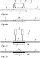
- Fig. 1a and 1b show a non-inventive device 1 for connecting or splicing two transfer or laminating film webs 2 and 2 'by means of ultrasonic welding in a schematic representation.
- the foils are transfer foils designed as hot stamping foils.
- the band-shaped film webs 2 and 2 ' are provided on supply rolls 2v and fed receiving devices 4 and 4', which fix the end portions of the film webs.
- the film webs are present as a film roll, which are connected in the device 1 to larger film wraps.
- the films are multilayer bodies which comprise a thermoplastic carrier film and a decorative layer which can be pulled off from the carrier film and formed as a transfer layer.
- the films have a separating layer arranged between the carrier film and the transfer layer, which facilitates the detachment of the transfer layer from the carrier film. Furthermore, reflection layers and protective layers can be provided, as described below Fig. 8 described.
- the receiving device 4 is connected to an adjusting device 4j motion-rigid.
- the receiving device 4 in x- and y-direction adjustable, whereby the two film webs 2 and 2 'to each other are positionally adjustable.
- the two film webs 2 and 2 ' are aligned with each other so that arranged on the first film web 2 motifs and / or registration marks to those on the second film web 2 'arranged motifs and / or registration marks are aligned in the register with a positional tolerance less than +/- 0.5 mm and thereby form a lap joint 3, in which they are arranged one above the other.
- the film webs 2 and 2 ' lie in the overlap joint 3 on an anvil 5, which is arranged under an ultrasonic welding head 6.
- the ultrasonic welding head 6 comprises an ultrasonic transducer 6w, an amplitude transformation piece 6a and a sonotrode 6s.
- a high-frequency alternating current is transmitted, from which with the aid of the piezoelectric or the magnetostrictive effect, a mechanical ultrasonic vibration is generated.
- the ultrasonic vibration is transmitted to the sonotrode 6s via the amplitude transformation piece 6a.
- the shape and mass of the amplitude transformation piece 6a affect the amplitude of the ultrasonic vibration and the impedance matching.
- the sonotrode 6s can be made of steel, aluminum or titanium.
- the sonotrode 6s points in the in Fig. 1a and 1b illustrated embodiment on two spaced-apart tips.
- the two tips of the sonotrode 6s come into contact with the film web 2 lying on top in the lap 3 and transmit the ultrasonic vibrations to the film material.
- the anvil 5 forms an abutment for the sonotrode 6s.
- the ultrasonic vibrations are thus transferred under pressure to the film webs 2 and 2 'to be joined, which are arranged one above the other in the lap 3 on the anvil 5.
- the areas of the film webs 2 and 2 'in contact with the sonotrode 6s heat up because of the Ultrasonic induced internal friction and merge with each other.
- the lowered ultrasonic welding head 6 is movable transversely to the longitudinal axis of the film webs 2 and 2 ', so that a double seam of two parallel welds 3n can be produced because of the two tips of the sonotrode 6s (see FIG Fig. 2a and 2b ) which extend over the entire width of the film webs 2 and 2 '.
- Fig. 2a and 2b show the interconnected film webs in Fig. 1 in a schematic perspective view or in a schematic sectional view.
- the film webs 2 and 2 ' are connected to each other by a double seam formed of two welds 3n.
- the ultrasonic welding head 6 um its longitudinal axis (z-axis, corresponding to the lowering direction) is rotatable.
- the two tips of the sonotrode 6s can also be rotated during the rectilinear method of the ultrasonic welding head 6 transversely to the longitudinal axis or running direction of the film webs 2, 2 'in such a way that an oscillating double seam results from two parallel, non-linear single seams.
- the resulting, in particular complex shape, in particular the density of the intersecting connecting seams, ie their respective distance from each other can be controlled.
- the oscillating double seam can in particular be shaped similar to a guilloche.
- Such a close-fitting double seam can have increased strength, in particular against tensile forces during processing and / or rolling up of the film webs 2, 2 '.
- the Fig. 3 shows a second embodiment of the device 1, in which the sonotrode 6s are designed as a roller sonotrode and the anvil 5 as a roller anvil.
- the representation of the device in Fig. 3 Essentially, like the device in Fig. 1 is formed, is limited to simplify the presentation on the sonotrode and the anvil.
- the Fig. 4a shows a schematic section of a third embodiment of the device 1, which essentially like the device in Fig. 1 is trained.
- the two film webs 2 and 2 'abut each other to form a butt joint and are in Connecting portion of a splice 7 covered.
- the splice 7, like the carrier film of the two film webs, can consist of a thermoplastic plastic material. It can be supplied to the device 1, for example, as a tape, which is cut to the width of the film webs after welding.
- a double seam may be provided, which is formed of two welds 3n.
- the advantage of this embodiment is that the two welds 3n are formed directly between the thermoplastic plastics materials which can be welded together, so that the welds are formed with optimum tensile strength.
- Fig. 5a to 5d show an embodiment in which the end portions of the film webs 2 and 2 'are each bent or folded by 90 ° and thus form a folding portion 2f and 2f. This results in increased strength in one of the weld seams 3n, because the carrier foils of the two film webs lie on one another due to the folding in the fold section and the carrier foils interlock with one another or interlock with one another counter to the direction of a later tensile loading.
- Fig. 6a and 6b show a further embodiment in which contact welding is provided as a connection method.
- a contact welding head 8 is provided which has two spaced-apart wire or ribbon-shaped heating elements 8h on its underside facing the overlap joint, which form two weld seams 3n by local thermal melting of the carrier foils when the contact welding head 8 is lowered onto the film webs 2 and 2 'to be joined.
- mixed layers are formed in the welds, as described below Fig. 8 described.
- the Fig. 7a and 7b show a further embodiment in which the film webs 2 and 2 'are joined together by laser welding.
- two laser welding heads 9 spaced apart from one another are provided, which enable a linear heating of the film webs 2 and 2 'to be joined.
- the laser welding heads 9 can be designed to be displaceable along the seam axis, or non-displaceable laser welding heads can be provided with an optical beam deflection.
- the laser welding heads 9 facing top of the recording device is transparent to the laser radiation used.
- the two film webs 2 and 2 ' form a butt joint, under which an absorption layer 10 designed as a black splice film for the laser radiation is arranged. Under the splice foil, the anvil 5 is arranged.
- the two film webs 2 and 2 'are advantageously aligned so that the carrier film rests on the splice film.
- the contact welding head 8 with two or more heating elements 8h or the laser welding head 9 equipped with two or more laser beams so is by rotation of the contact welding head 8 about its longitudinal axis or in the case of the laser welding head 9 by rotation of the laser welding head 9 about its longitudinal axis or by appropriate Adjustment of the optical beam deflection producing complex, in particular oscillating multiple seams with increased strength produced. It is also possible here to combine the multiple seams with the previously described width variations of the seam and / or seam breaks.
- the Fig. 8 shows a schematic sectional view of the layer structure of two welded together film webs 2 and 2 'and the formation of the welds 3n in detail.
- the two film webs 2 and 2 ' are formed as a multi-layer body.
- HRI high refractive index
- ZnS or TiO 2 or from a multi-layer system over the entire surface or structured z. B. be formed by partial metallization or demetalization. Combinations of these are also possible.
- an adhesive layer may be provided.
- the starting material has a tensile strength of 40-45 N / cm at a thickness of 19 microns.
- Conventional adhesive coated splice tape has a tensile strength of 30-40 N / cm. In a conventional splice and a PET film of 19 .mu.m thickness, a tensile strength of 35-45 N / cm is achieved.
- the inventively welded splice of o. G. PET material had a tensile strength of 15-25 N / cm, which is sufficient for further processing of the bonded film webs in a roll-to-roll process.
- film webs of a hot stamping film were bonded by ultrasonic welding with a seam width of 0.6-1.0 mm, the tensile strength per seam being 12-19 N / cm.
- the width of the weld has a decisive influence on the tensile strength of the weld.
Landscapes
- Engineering & Computer Science (AREA)
- Mechanical Engineering (AREA)
- Physics & Mathematics (AREA)
- Optics & Photonics (AREA)
- Electromagnetism (AREA)
- Health & Medical Sciences (AREA)
- Toxicology (AREA)
- Lining Or Joining Of Plastics Or The Like (AREA)
- Laminated Bodies (AREA)
Description
- Die Erfindung betrifft ein Verfahren zum Verbinden zweier Transferfolienbahnen, die eine thermoplastische Trägerfolie und eine Dekorlage umfassen.
- Bei der Verarbeitung und Anwendung von Transferfolien und Laminierfolien müssen oftmals Folienabschnitte miteinander verbunden werden, um aus kürzeren Folienbahnen oder Streifen entsprechend längere "Lauflängen" zusammenzufügen.
- Bestimmte Lauflängen ergeben sich sowohl aus Kundenanforderungen, zum Beispiel um mit Schnittrollen hoher Länge die Produktivität zu steigern, als auch aus der Forderung, den Ausschuss zu minimieren, weil Rüst- oder Standzeiten, insbesondere zum Rollenwechsel, verringert werden.
- In der Folienherstellung und -verarbeitung ("Inhouse") besteht ebenfalls die Notwendigkeit, Folienbahnen miteinander zu verbinden, um die Produktivität zu erhöhen, den Ausschuss zu minimieren und um Rüstzeiten, Standzeiten und Anfahrprozesse zu verringern.
- Das gängigste Verfahren ist das Verbinden, auch "Spleißen" genannt, mittels insbesondere manuell angebrachter Klebebänder. Hierbei werden die entsprechenden Folien mit handelsüblichen selbstklebenden Klebebändern zusammengeklebt. Die Verklebung erfolgt bei Laminier- oder Transferfolien (einseitig mit einer Transferlage beschichtete Folien) typischerweise auf der unbeschichteten Folienseite. Die Breite des Klebebandes ist typisch im Bereich von 2 bis 5 cm. Typische Dicken von Klebebändern liegen im Bereich von ca. 30 bis 130 µm.
- Das Spleißen mit Klebeband hat sich in den letzten Jahren bewährt und bietet eine Reihe von Vorteilen. Das Verfahren ist kostengünstig, kann mit einer relativ hohen Passergenauigkeit der Folien zueinander erfolgen und der Spleiß, d. h. die Verbindungsstelle oder Verbindungsnaht, verfügt über hohe Festigkeiten, insbesondere Zugfestigkeit in Laufrichtung der Folien. Zudem kommen oftmals farbige Klebebänder zum Einsatz, um bestimmte Typen von Spleißen zu charakterisieren und optisch unterscheidbar zu machen.
- Spleißen mittels Klebebändern zeigt jedoch eine Reihe von Nachteilen.
- Beim Prägen von Einzelbildern sind diese Einzelbilder bzw. Motive, d. h. die Nutzen, in einem bestimmten Layout auf der Folie angeordnet, insbesondere in regelmäßigen Zeilen und Spuren. Dabei liegen die zu prägenden Nutzen in der Regel so nah zusammen, dass das Klebeband im Bereich der Prägezone liegt und dabei im Bereich der zu prägenden Nutzen, so dass diese überlappten Nutzen nicht prägbar sind und verloren gehen. Dies kann insbesondere zu Fehlprägungen und/oder zu Verschmutzungen der Prägestempel durch das Klebeband bzw. durch den am Rand austretenden Kleber des Klebebandes führen. Deshalb wird der Spleiß detektiert und ein Folienvorschub durchgeführt, wodurch ein Materialverlust eintritt und die Produktivität vermindert wird.
- Beim Prägen von Einzelbildern auf parallelen Spuren besteht zusätzlich die Forderung, dass die Spleißstellen zum gleichen Zeitpunkt an der Prägeeinheit ankommen, da der Prägevorgang an allen Spuren unterbrochen werden muss bzw. alle Nutzen gleichzeitig übersprungen werden müssen und alle diese Nutzen verloren gehen. Liegen die Spleiße an unterschiedlichen Stellen in den Folien, so ist der Prägeprozess für längere Zeiten zu unterbrechen bzw. muss mehrmals wiederholt werden.
- Beim Prägen von Einzelbildern mittels Mehrfachapplikation treten zusätzliche Probleme auf. Hier muss der Repeat der Einzelbilder, das heißt der Abstand der Einzelbilder zueinander, sehr genau stimmen. Aus diesem Grund können nur Folienstücke mit gleichem Repeat zusammen gespleißt werden.
- Innerhalb von gespleißten Rollen kann es an der Spleißstelle - bedingt durch den höheren Druck - zu Kaltkleberaustritt am Rand des Spleißbandes oder zum "Verblocken" der Rollen, d. h. zum Verkleben von benachbarten Windungen auf der Rolle, kommen.
- Der Einsatz von Klebeband-Spleißen erfordert einen höheren steuerungstechnischen Aufwand.
- Die Verwendung von schmäleren Klebebändern mit einer Breite kleiner 1 cm ist in der Regel nicht möglich, da mit schmalen Klebebändern die erforderlichen Festigkeiten, insbesondere Zugfestigkeiten während der Verarbeitung, nicht sicher erreicht werden und sich die Spleißstelle auch durch Zugkräfte beim Wickeln bzw. innerhalb der Rolle öffnen kann.
- Die
DE 102 26 148 A1 betrifft eine Vorrichtung zum Verkleben zweier Bahnen aus Verpackungsmaterial für die Herstellung flüssigkeitsdichter Packungen, wobei jede Bahn zumindest einseitig mit einer flüssigkeitsdichten Kleberschicht abgedeckt ist. - Die
JP 2004/256268 A - Die
EP 1 184 311 A1 betrifft ein Verfahren zum Spleißen eines Laminats für die Verpackung von gießbaren Lebensmitteln. - Die
EP 2 216 279 A1 beschreibt ein Verfahren zum Verbinden von Folienbahnen aus einem Laminat auf Stoß. - Die
US 4 259 399 A betrifft ein Verfahren zur Herstellung eines leichten Vliesstoffgewebes aus einem Bündel von zufälligen, losen, ultraschallverschmelzbaren Fasern. - Aufgabe der vorliegenden Erfindung ist es, ein verbessertes Verfahren und eine verbesserte Vorrichtung anzugeben, die die genannten Nachteile vermeiden.
- Erfindungsgemäß wird diese Aufgabe mit einem Verfahren zum Verbinden einer ersten und einer zweiten Folienbahn einer Transferfolie gelöst, wobei die Folienbahnen eine thermoplastische Trägerfolie und eine Dekorlage umfassen, wobei eine solche erste und zweite Folienbahn miteinander verbunden werden, die eine Trennschicht aufweisen, um das Ablösen der Dekorlage von der thermoplastischen Trägerfolie zu erleichtern, und wobei vorgesehen ist, dass zwischen der ersten und der zweiten Folienbahn ein gemeinsamer Verbindungsabschnitt ausgebildet wird, in dem die erste und die zweite Folienbahn durch ein Schweißverfahren derart miteinander verbunden werden, dass die erste und zweite Folienbahn durch eine Doppelnaht, gebildet aus zwei Schweißnähten, miteinander verbunden sind.
- Überraschender Weise hat sich gezeigt, dass eine dauerhafte und belastbare Schweißverbindung eintritt, obwohl die zu verschweißenden Folienbahnen als Mehrschichtkörper ausgebildet sind, die neben der verschweißbaren thermoplastischen Trägerfolie weitere Schichten umfassen, die die Festigkeit der Schweißverbindung herabsetzen können oder diese verhindern können.
- Zudem weisen die Folien nach dem Schweißen eine sehr gute Planlage ohne nachteilige Verdickungsstelle durch ein zusätzliches Klebeband im Bereich der Naht auf und zeigen praktisch keine Dimensionsänderungen, insbesondere ein- oder zweidimensionale Verzüge, was zum Beispiel für Folgeprozesse wie Schneid- und Konfektionierungsprozesse von großer Bedeutung ist.
- Bei den Transferfolien handelt es sich um Folien, deren Dekorlage durch ein Prägewerkzeug mittels Druck und/oder Temperatur auf ein zu dekorierendes Substrat übertragen wird. Die Basis der Transferfolie bildet eine Trägerfolie aus einem thermoplastischen Kunststoff, auf der eine ablösbare Dekorlage angeordnet ist.
- Die Dekorlage kann neben einer oder mehreren, das Dekor tragenden Dekorschichten weitere Schichten umfassen, beispielsweise eine Kleberschicht und eine Aktivierungsschicht für die Kleberschicht.
- Die eine Dekorschicht oder die mehreren Dekorschichten können beispielsweise jeweils als eine optional eingefärbte, transparente, transluzente oder opake Lackschicht, als eine fluoreszierende oder phosphoreszierende Lackschicht, als eine optisch variable Schicht und/oder als eine metallische oder nichtmetallische Reflexionsschicht ausgebildet sein. So kann eine Dekorschicht als eine pigmentierte Lackschicht ausgebildet sein, so dass Farbwirkungen ausbildbar sind und Bilder sowie alphanumerische Zeichen oder Symbole darstellbar sind. Die Dekorschicht kann eine funktionale Schicht, beispielsweise eine Magnetschicht, eine Photopolymerschicht oder eine Schicht aus leitenden, halbleitenden oder nichtleitenden Polymeren sein. Folien mit derartigen Dekorschichten können im Bereich von Magnetfolien, zum Fälschungsschutz von Banknoten und Dokumenten, für Außenanwendungen, zum Beispiel Chromfolien für Nummernschilder oder andere Dekore, im Bereich der IMD- oder IML-Technologie (IMD = In Mould Decoration; IML = In Mould-Labeling), für Antennenanwendungen sowie für Label unterschiedlichster Anwendungen zum Einsatz kommen. Zudem sind Kombinationen der genannten Dekorschichten ausführbar, wobei in einer Dekorschicht unterschiedliche Schichten direkt oder indirekt nebeneinander vorliegen. Die Schichtdicke einer solchen Dekorschicht beträgt vorzugsweise zwischen 1 µm und 25 µm, weiter bevorzugt zwischen 1 µm und 5 µm. Eine optisch variable Schicht kann von einer Replizierlackschicht mit einem abgeformten, diffraktiv und/oder refraktiv wirkenden Oberflächenrelief, einer Hologrammschicht, einer Volumenhologrammschicht, einem Dünnfilmschichtsystem, welches Farbwechseleffekte mittels Interferenz erzeugt, einer Flüssigkristallschicht oder einer Pigmente enthaltenden Schicht gebildet sein, beispielsweise optisch variable Interferenzschichtpigmente oder optisch variable Flüssigkristallpigmente oder Metall- oder Metalloxidpigmente. Als Oberflächenrelief kann beispielsweise eine refraktiv wirkende Makrostruktur, beispielsweise eine Linsenstruktur, ein diffraktives Beugungsgitter oder ein Hologramm abgeformt sein, welches vorzugsweise mit einer Reflektionsschicht belegt ist. Zur Unterstützung der optischen Effekte können metallische Schichten vorgesehen sein, die einfallendes Licht zurückwerfen. Die Dekorschichten können bereichsweise unterschiedlich ausgebildet sein und beliebig miteinander kombiniert sein, so dass beispielsweise OVD-Bereiche (Optically Variable Device) und Bildbereiche nebeneinander oder überlagernd dargestellt sind.
- Bei Laminierfolien ist eine Trennung der Dekorlage von der Trägerfolie nicht vorgesehen. Zwischen der Dekorlage und der Trägerfolie kann daher eine Haftvermittlerschicht vorgesehen sein. Die Dekorlage kann neben einer oder mehreren Dekorschichten weiter eine Kleberschicht umfassen. Es kann sich dabei um eine Heißkleberschicht oder eine Kaltkleberschicht handeln. Die Dekorschichten können wie die Dekorschichten der Transferfolie ausgebildet sein.
- Die einzelnen Schichten des Folienaufbaus können aus thermoplastischem Material, duroplastischem Material, zum Beispiel aus Lacken, die mittels UV-Strahlung vernetzt werden können, sowie aus Hybridmaterial (thermoplastisch, d. h. thermisch trocknend und gleichzeitig mit Strahlung vernetzbar) oder Kombinationen davon bestehen.
- Die Schichtabfolgen können auch mehrfach vorliegen. Möglich ist auch, dass eine Dekorlage aus funktionalen und/oder dekorativen Schichten auf beiden Seiten der Trägerfolie vorliegt.
- Insbesondere von den Trennschichten, bei denen es sich vorzugsweise um Wachstrennschichten handelt, welche bei Aktivierung mittels Wärme beim Heißprägen erweicht werden und dadurch ihre Trennfunktion erfüllen, und von den Metallisierungsschichten war zu erwarten, dass sie die Festigkeit der Schweißverbindung so stark herabsetzen, dass eine sichere Verbindung zweier Folienbahnen nicht möglich ist.
- Mit dem erfindungsgemäßen Verfahren und der erfindungsgemäßen Vorrichtung können überraschenderweise dennoch Folien mit hoher Genauigkeit durch eine Schweißverbindung gespleißt werden, wobei ein Verbindungsabschnitt ausgebildet wird, der im Rolle-zu-Rolle-Prozess zu keiner Produktionsstörung führt.
- Es kann vorgesehen sein, dass der gemeinsame Verbindungsabschnitt als ein Überlappungsstoß ausgebildet wird. Der Überlappungsstoß kann mit besonders geringer Breite ausgebildet werden, so dass auch Folien spleißbar sind, deren Motivabstand innerhalb des Layouts der Motive so gering ist, dass bei Verwendung von Spleißband die dem Verbindungsabschnitt benachbarten Motive nicht abprägbar wären.
- Es kann auch vorgesehen sein, dass der gemeinsame Verbindungsabschnitt als ein Stumpfstoß, der von einer Spleißfolie überdeckt ist, ausgebildet wird. Bei der Spleißfolie handelt es sich allerdings nicht um ein Klebeband, so dass Verschmutzungen durch Austritt von Kleber nicht auftreten können. Die Spleißfolie kann auch eine geringere Dicke als ein Klebeband aufweisen, insbesondere eine Dicke von etwa 5 µm bis 20 µm aufweisen.
- Es kann weiter vorgesehen sein, dass die erste und die zweite Folienbahn mittels Ultraschallschweißen miteinander verbunden werden.
- In einer weiteren Ausführung kann vorgesehen sein, dass die erste und die zweite Folienbahn mittels Kontaktschweißen miteinander verbunden werden. Beim Kontaktschweißen werden erhitzte Abschnitte des Schweißkopfes mit dem Verbindungsabschnitt in thermischen Kontakt gebracht, so dass ein lokales Aufschmelzen der beiden Folienbahnen erfolgt, die dadurch miteinander verschweißt werden.
- Es kann vorgesehen sein, dass zur Ausbildung einer Schweißnaht ein erhitztes Band oder ein erhitzter Draht verwendet wird.
- Weiter kann vorgesehen sein, dass die erste und die zweite Folienbahn mittels Laserschweißen miteinander verbunden werden. Es kann vorgesehen sein, einen Laser längs der Schweißnaht zu bewegen und/oder das Laserlicht optisch so abzulenken, dass es eine Linie ausbildet.
- Es kann vorgehen sein, dass in dem Verbindungsabschnitt unter der ersten und der zweiten Folienbahn eine Absorptionsschicht für Laserlicht angeordnet wird. Die Absorptionsschicht wandelt das Laserlicht in Wärme um. Dadurch ist es insbesondere möglich, geringere Laserleistungen zu verwenden. Durch die Absorptionsschicht ist es außerdem möglich, die auf die Schweißstelle einwirkende Energie auch rückseitig in die Schweißstelle einzutragen, d.h. von der dem Laserlicht abgewandten Seite. Die Absorptionsschicht kann als oberste Schicht oder unter einer anderen Schicht innerhalb einer mehrschichtigen Dekorlage angeordnet sein. Möglich ist auch der Einsatz mehrerer Absorptionsschichten, ggf. an unterschiedlichen Positionen innerhalb der Dekorlage und mit ggf. unterschiedlicher Absorptionscharakteristik für Laserlicht.
- In einer vorteilhaften Ausbildung kann vorgesehen sein, dass als Absorptionsschicht eine das Laserlicht absorbierende Spleißfolie verwendet wird. Bei der Spleißfolie handelt es sich allerdings nicht um ein Klebeband, so dass Verschmutzungen durch Austritt von Kleber nicht auftreten können. Vorteilhafterweise kann es sich um eine eingefärbte Folie aus dem Material der Trägerfolie handeln.
- Die Schnittkanten der Folien können geradlinig ausgebildet sein. Möglich ist auch der Einsatz von wellenförmig geschnittenen, perforierten, gezackten Kanten usw.
- Es kann vorgesehen sein, dass eine kontinuierliche Schweißnaht ausgebildet wird. In der einfachsten Form kann es sich um eine geradlinige kontinuierliche Einfach- oder Mehrfachnaht handeln. Die kontinuierliche Schweißnaht kann auch wellenförmig, gezackt oder mäanderförmig ausgebildet sein. Der Schweißkopf, beispielsweise der Kontaktschweißkopf, der Laserstrahl oder die Sonotrode, kann der genannten Nahtkontur entsprechend über die Folienoberfläche bewegt werden oder es kann ein entsprechend ausgeformter Schweißdraht vorgesehen sein.
- Es kann auch vorgesehen sein, dass eine diskontinuierliche Schweißnaht ausgebildet wird. So können insbesondere gestrichelte oder gepunktete Schweißnähte ausgebildet werden, indem beispielsweise der Laserstrahl ein- und ausgeschaltet wird, der Kontaktschweißkopf oder die Sonotrode ein- und ausgeschaltet oder von der Folienoberfläche abgehoben und wieder aufgesetzt wird.
- Weiter kann vorgesehen sein, dass eine Schweißnaht in oszillierender Form ausgebildet wird. Bei einer oszillierenden Schweißnaht kann die Lage der Schweißnaht und/oder die Breite der Schweißnaht variiert sein. Es kann beispielsweise der Fokus des Laserstrahls verändert werden. Weiter kann vorgesehen sein, Kontaktschweißköpfe oder Sonotroden mit länglichem Querschnitt, beispielsweise rechteckförmigem oder elliptischen Querschnitt zu verwenden und diese um ihre Längsachse zu drehen oder zu schwenken. Die Breite der Schweißnaht kann bei dieser Ausbildung variiert werden, indem durch die Drehlage des Schweißkopfes unterschiedlich effektive Breiten des Schweißkopfes eingestellt werden. Die effektive Breite des Schweißkopfes variiert so zwischen der Abmessung der Schmalseite des Rechtecks oder der Ellipse und der Abmessung der Breitseite des Rechtecks oder der Ellipse.
- In einer weiteren vorteilhaften Ausbildung kann vorgesehen sein, dass die Dekorlage vor dem Schweißprozess im Bereich der Schweißnaht entfernt wird. Das Entfernen der Dekorlage kann durch in Kontakt bringen mit einem selbstklebenden Klebeband mit nachfolgendem Abziehen der Dekorlagen oder durch vorgängiges Transferieren auf eine Unterlage mittels eines zum Beispiel 3 mm breiten beheizten Prägerades erfolgen.
- Möglich ist auch die vorgängige Modifikation, insbesondere Ablation oder thermische Zerstörung, der Dekorlage mittels Lasereinwirkung.
- Weiter kann vorgesehen sein, dass die erste und die zweite Folienbahn so zueinander ausgerichtet werden, dass die auf der ersten Folienbahn angeordneten Motive und/oder Passmarken zu den auf der zweiten Folienbahn angeordneten Motive und/oder Passmarken im Verbindungsabschnitt im Register mit einer Lagetoleranz kleiner als +/-0,5 mm ausgerichtet sind. Wenn die Motive klare Konturen aufweisen, beispielsweise scharfe Kanten und/oder Konturen, können Passmarken entbehrlich sein.
- Die Erfindung wird nun anhand von Ausführungsbeispielen näher erläutert. Es zeigen
- Fig. 1a
- ein nicht erfindungsgemäßes erstes Ausführungsbeispiel einer Vorrichtung zum Verbinden zweier Transfer- oder Laminierfolienbahnen in schematischer Seitenansicht;
- Fig. 1b
- die Vorrichtung in
Fig. 1a in schematischer Draufsicht; - Fig. 2a
- die miteinander verbundenen Folienbahnen in
Fig. 1a in schematischer perspektivischer Darstellung; - Fig. 2b
- die miteinander verbundenen Folienbahnen in
Fig. 1a in schematischer Schnittdarstellung; - Fig. 3
- ein nicht erfindungsgemäßes zweites Ausführungsbeispiel einer Vorrichtung zum Verbinden zweier Transfer- oder Laminierfolienbahnen in schematischer perspektivischer Darstellung;
- Fig.4a
- ein nicht erfindungsgemäßes drittes Ausführungsbeispiel einer Vorrichtung zum Verbinden zweier Transfer- oder Laminierfolienbahnen in schematischer Schnittdarstellung;
- Fig. 4b
- die miteinander verbundenen Folienabbahnen in
Fig. 4a in schematischer Schnittdarstellung; - Fig. 5a
- eine erste Vorbereitungsstufe der Folienendabschnitte für ein in
Fig. 5c gezeigtes viertes Ausführungsbeispiel einer nicht erfindungsgemäßen Vorrichtung zum Verbinden zweier Transfer- oder Laminierfolienbahnen in schematischer Schnittdarstellung; - Fig. 5b
- eine zweite Vorbereitungsstufe der Folienendabschnitte in
Fig. 5a ; - Fig. 5c
- ein nicht erfindungsgemäßes viertes Ausführungsbeispiel einer Vorrichtung zum Verbinden zweier Transfer- oder Laminierfolienbahnen in schematischer Schnittdarstellung;
- Fig. 5d
- die miteinander verbundenen Folienbahnen in
Fig. 5c in schematischer Schnittdarstellung; - Fig. 6a
- ein nicht erfindungsgemäßes fünftes Ausführungsbeispiel einer Vorrichtung zum Verbinden zweier Transfer- oder Laminierfolienbahnen in schematischer Schnittdarstellung;
- Fig. 6b
- die miteinander verbundenen Folienbahnen in
Fig. 6a in schematischer Schnittdarstellung; - Fig. 7a
- ein nicht erfindungsgemäßes sechstes Ausführungsbeispiel einer Vorrichtung zum Verbinden zweier Transfer- oder Laminierfolienbahnen in schematischer Schnittdarstellung;
- Fig. 7b
- die miteinander verbundenen Folienbahnen in
Fig. 7a in schematischer Schnittdarstellung; - Fig. 8
- die miteinander verschweißten Folienendabschnitte im Schichtaufbau in einer schematischen Schnittdarstellung;
- Fig.9a
- ein Schnittbild einer Folienschweißverbindung in 10facher Vergrößerung;
- Fig. 9b
- ein Schnittbild einer Folienschweißverbindung in 20facher Vergrößerung.
-
Fig. 1a und 1b zeigen eine nicht erfindungsgemäße Vorrichtung 1 zum Verbinden bzw. Spleißen zweier Transfer- oder Laminierfolienbahnen 2 und 2' mittels Ultraschallschweißen in schematischer Darstellung. In dem inFig. 1a und 1b gezeigten Ausführungsbeispiel handelt es sich bei den Folien um als Heißprägefolie ausgebildete Transferfolien. - Die bandförmigen Folienbahnen 2 und 2' sind auf Vorratsrollen 2v bereitgestellt und Aufnahmevorrichtungen 4 und 4' zugeführt, welche die Endabschnitte der Folienbahnen fixieren. Die Folienbahnen liegen als Folienwickel vor, die in der Vorrichtung 1 zu größeren Folienwickeln verbunden werden. Bei den Folien handelt es sich um Mehrschichtkörper, die eine thermoplastische Trägerfolie und eine von der Trägerfolie abziehbare, als Übertragungslage ausgebildete Dekorlage umfassen. Die Folien weisen eine zwischen der Trägerfolie und der Übertragungslage angeordnete Trennschicht auf, die das Ablösen der Übertragungslage von der Trägerfolie erleichtert. Weiter können Reflexionsschichten und Schutzschichten vorgesehen sein, wie weiter unten in
Fig. 8 beschrieben. - Die Aufnahmevorrichtung 4 ist mit einer Justiereinrichtung 4j bewegungsstarr verbunden. Mittels der Justiereinrichtung 4j ist die Aufnahmevorrichtung 4 in x- und y-Richtung verstellbar, wodurch die beiden Folienbahnen 2 und 2' zueinander lagejustierbar sind. Mit der Justiereinrichtung 4j können die zwei Folienbahnen 2 und 2' so zueinander ausgerichtet werden, dass die auf der ersten Folienbahn 2 angeordneten Motive und/oder Passmarken zu den auf der zweiten Folienbahn 2' angeordneten Motive und/oder Passmarken im Register mit einer Lagetoleranz kleiner als +/-0,5 mm ausgerichtet sind und dabei einen Überlappungsstoß 3 bilden, in dem sie übereinander angeordnet sind. Die Folienbahnen 2 und 2' liegen im Überlappungsstoß 3 auf einem Amboss 5 auf, der unter einem Ultraschallschweißkopf 6 angeordnet ist. Der Ultraschallschweißkopf 6 umfasst einen Ultraschallwandler 6w, ein Amplitudentransformationsstück 6a und eine Sonotrode 6s.
- Zu dem Ultraschallwandler 6w wird ein hochfrequenter Wechselstrom übertragen, aus dem mit Hilfe des piezoelektrischen oder des magnetostriktiven Effekts eine mechanische Ultraschallschwingung erzeugt wird. Die Ultraschallschwingung wird über das Amplitudentransformationsstück 6a auf die Sonotrode 6s übertragen. Durch die Form und Masse des Amplitudentransformationsstückes 6a werden die Amplitude der Ultraschallschwingung und die Impedanzanpassung beeinflusst. Die Sonotrode 6s kann aus Stahl, Aluminium oder Titan hergestellt sein.
- Die Sonotrode 6s weist in dem in
Fig. 1a und 1b dargestellten Ausführungsbeispiel zwei voneinander beabstandete Spitzen auf. Die zwei Spitzen der Sonotrode 6s kommen durch Absenken des Ultraschallschweißkopfes 6 mit der im Überlappungsstoß 3 obenauf liegenden Folienbahn 2 in Anlage und übertragen die Ultraschallschwingungen auf das Folienmaterial. Dabei bildet der Amboss 5 ein Gegenlager für die Sonotrode 6s. Die Ultraschallschwingungen werden so unter Druck auf die zu verbindenden Folienbahnen 2 und 2' übertragen, die in dem Überlappungsstoß 3 auf dem Amboss 5 übereinander angeordnet sind. Die mit der Sonotrode 6s in Kontakt stehenden Bereiche der Folienbahnen 2 und 2' erhitzen sich wegen der durch den Ultraschall hervorgerufenen inneren Reibung und verschmelzen miteinander. - Der abgesenkte Ultraschallschweißkopf 6 ist quer zu der Längsachse der Folienbahnen 2 und 2' verfahrbar, so dass wegen der zwei Spitzen der Sonotrode 6s eine Doppelnaht aus zwei parallelen Schweißnähten 3n herstellbar ist (siehe
Fig. 2a und 2b ), die über die gesamte Breite der Folienbahnen 2 und 2' erstreckt sind. - Überraschender Weise hat sich gezeigt, dass eine dauerhafte und belastbare Schweißverbindung eintritt, obwohl zwischen den beiden Trägerfolien im Überlappungsstoß 3 die besagten weiteren Schichten angeordnet sind, so dass die beiden Trägerfolien nicht im direkten Kontakt stehen. Es war zu erwarten, dass insbesondere Wachs auch beim Ultraschallschweißen durch Aufschmelzen durch den Energieeintrag als Trennmittel wirkt und eine haltbare Verschweißung verhindert. Weiter unten in
Fig. 8 wird ein möglicher Wirkungsmechanismus beschrieben, der zu der belastbaren Schweißverbindung führt. -
Fig. 2a und 2b zeigen die miteinander verbundenen Folienbahnen inFig. 1 in schematischer perspektivischer Darstellung bzw. in schematischer Schnittdarstellung. Die Folienbahnen 2 und 2' sind durch eine Doppelnaht, gebildet aus zwei Schweißnähten 3n, miteinander verbunden. - Alternativ zu der Doppelnaht aus zwei geradlinigen parallelen Einzelnähten sind auch andere Doppelnähte ausführbar, wenn der Ultraschallschweißkopf 6 um seine Längsachse (z-Achse, entsprechend der Absenkrichtung) drehbar ist. Dadurch können auch die zwei Spitzen der Sonotrode 6s so während des geradlinigen Verfahrens des Ultraschallschweißkopfes 6 quer zur Längsachse bzw. Laufrichtung der Folienbahnen 2, 2' so verdreht werden, dass eine oszillierende Doppelnaht aus zwei parallelen, nicht geradlinigen Einzelnähten entsteht. Je nach Größe der Verfahr- und Drehgeschwindigkeit lässt sich die resultierende, insbesondere komplexe Form, insbesondere auch die Dichte der sich kreuzenden Verbindungsnähte, d. h. deren jeweiliger Abstand zueinander, steuern. Die oszillierende Doppelnaht kann insbesondere ähnlich einer Guilloche geformt sein. Eine solche dicht an dicht angeordnete Doppelnaht kann eine erhöhte Festigkeit, insbesondere gegen Zugkräfte bei der Verarbeitung und/oder dem Aufrollen der Folienbahnen 2, 2' aufweisen. Es ist ebenso möglich, die Sonotrode mit mehr als zwei Spitzen auszurüsten, sodass entweder geradlinig parallele Mehrfachnähte entstehen oder wie oben beschrieben, entsprechend noch komplexere, nicht geradlinige Mehrfachnähte. Es ist ebenso möglich, die Mehrfachnähte mit den vorher beschriebenen Breitenvariationen der Naht und/oder Naht-Unterbrechungen zu kombinieren.
- Die
Fig. 3 zeigt ein zweites Ausführungsbeispiel der Vorrichtung 1, bei dem die Sonotrode 6s als eine Rollsonotrode und der Amboss 5 als ein Rollamboss ausgebildet sind. Die Darstellung der Vorrichtung inFig. 3 , die im Wesentlichen wie die Vorrichtung inFig. 1 ausgebildet ist, ist zur Vereinfachung der Darstellung auf die Sonotrode und den Amboss beschränkt. - Die
Fig. 4a zeigt einen schematischen Ausschnitt eines dritten Ausführungsbeispiels der Vorrichtung 1, die im Wesentlichen wie die Vorrichtung inFig. 1 ausgebildet ist. Die beiden Folienbahnen 2 und 2' stoßen unter Ausbildung eines Stumpfstoßes aneinander und sind im Verbindungsabschnitt von einem Spleiß 7 überdeckt. Der Spleiß 7 kann wie die Trägerfolie der beiden Folienbahnen aus einem thermoplastischen Kunststoffmaterial bestehen. Er kann der Vorrichtung 1 beispielsweise als ein Band zugeführt werden, das nach dem Schweißen auf die Breite der Folienbahnen zugeschnitten wird. Wie inFig. 4b gezeigt, kann eine Doppelnaht vorgesehen sein, die aus zwei Schweißnähten 3n gebildet ist. Der Vorteil dieses Ausführungsbeispiels besteht darin, dass die beiden Schweißnähte 3n unmittelbar zwischen den miteinander verschweißbaren thermoplastischen Kunststoffmaterialien ausgebildet sind, so dass die Schweißnähte mit optimaler Zugfestigkeit ausgebildet sind. - Die
Fig. 5a bis 5d zeigen eine Ausbildung, bei der die Endabschnitte der Folienbahnen 2 und 2' jeweils um 90° umgebogen oder gefaltet werden und so einen Faltabschnitt 2f bzw. 2f bilden. Dadurch entsteht in einer der Schweißnähte 3n eine erhöhte Festigkeit, weil durch das Umfalten im Faltabschnitt die Trägerfolien der beiden Folienbahnen aufeinander liegen und die Trägerfolien entgegen der Richtung einer späteren Zugbelastung ineinander greifen bzw. miteinander verzahnen. - Die
Fig. 6a und 6b zeigen ein weiteres Ausführungsbeispiel, bei dem als Verbindungsverfahren Kontaktschweißen vorgesehen ist. Anstelle des Ultraschallschweißkopfes inFig. 1 ist ein Kontaktschweißkopf 8 vorgesehen, der an seiner dem Überlappungsstoß zugewandten Unterseite zwei voneinander beabstandete draht- oder bandförmige Heizelemente 8h aufweist, die beim Absenken des Kontaktschweißkopfes 8 auf die zu verbindenden Folienbahnen 2 und 2' zwei Schweißnähte 3n durch lokales thermisches Aufschmelzen der Trägerfolien ausbilden. Auch dabei bilden sich in den Schweißnähten Mischschichten heraus, wie weiter unten inFig. 8 beschrieben. - Die
Fig. 7a und 7b zeigen ein weiteres Ausführungsbeispiel, bei dem die Folienbahnen 2 und 2' durch Laserschweißen miteinander verbunden werden. In dem Ausführungsbeispiel sind zwei voneinander beabstandete Laserschweißköpfe 9 vorgesehen, die eine linienförmige Erwärmung der zu verbindenden Folienbahnen 2 und 2' ermöglichen. Dazu können die Laserschweißköpfe 9 längs der Nahtachse verschiebbar ausgebildet sein, oder es können nicht verschiebbare Laserschweißköpfe mit einer optischen Strahlablenkung vorgesehen sein. Die den Laserschweißköpfen 9 zugewandte Oberseite der Aufnahmevorrichtung ist für die verwendete Laserstrahlung durchsichtig ausgebildet. Die beiden Folienbahnen 2 und 2' bilden einen Stumpfstoß aus, unter dem eine als schwarze Spleißfolie ausgebildete Absorptionsschicht 10 für die Laserstrahlung angeordnet ist. Unter der Spleißfolie ist der Amboss 5 angeordnet. Die beiden Folienbahnen 2 und 2' sind vorteilhafterweise so ausgerichtet, dass die Trägerfolie auf der Spleißfolie aufliegt. - Ist der Kontaktschweißkopf 8 mit zwei oder mehr Heizelementen 8h oder der Laserschweißkopf 9 mit zwei oder mehr Laserstrahlen ausgerüstet, so ist auch damit durch Verdrehung des Kontaktschweißkopfes 8 um seine Längsachse oder im Falle des Laserschweißkopfes 9 durch Verdrehung des Laserschweißkopfes 9 um seine Längsachse oder durch entsprechende Verstellung der optischen Strahlablenkung die Erzeugung komplexer, insbesondere oszillierender Mehrfachnähte mit erhöhter Festigkeit herstellbar. Es ist auch hier möglich, die Mehrfachnähte mit den vorher beschriebenen Breitenvariationen der Naht und/oder Naht-Unterbrechungen zu kombinieren.
- Die
Fig. 8 zeigt anhand einer schematischen Schnittdarstellung den Schichtaufbau zweier miteinander verschweißter Folienbahnen 2 und 2' sowie die Ausbildung der Schweißnähte 3n im Einzelnen. - Die beiden Folienbahnen 2 und 2' sind als Mehrschichtkörper ausgebildet. Auf einer Trägerfolie 21, die beispielsweise aus Polyester, insbesondere PET (PET = Polyethylenterephthalat) ausgebildet sein kann, ist eine wachsartige Trennschicht 22, eine Übertragungslage 23 und eine insbesondere metallische Reflexionsschicht 24 angeordnet. Die Reflexionsschicht kann beispielsweise aus Metallen wie Aluminium, Kupfer, Chrom oder aus HRI-Schichten (HRI = high refractive index) wie z. B. ZnS oder TiO2 oder aus einem Mehrschichtsystem vollflächig oder strukturiert, z. B. durch partielle Metallisierung oder Demetallisierung ausgebildet sein. Kombinationen davon sind ebenfalls möglich. Als weitere Schicht kann beispielsweise eine Kleberschicht vorgesehen sein.
- Wie Untersuchungen gezeigt haben, sind in den Schweißnähten 3n Mischstrukturen ausgebildet, wobei die Trägerfolien 21 eine durchgehende Verbindungsschicht bilden, in der Cluster der übrigen Schichten eingelagert sind. Wie die
Fig. 9a und 9b zeigen, ist eine Durchmischung des Schichtpakets eingetreten. Die Mischschicht ist zwar nicht so homogen wie die Trägerfolie, weist jedoch noch eine ausreichende Zugfestigkeit auf, um das Abprägen bzw. Aufkaschieren der Folie zu ermöglichen, wie weiter oben beschrieben. - Wie Versuche mit unterschiedlichen Schweißverfahren zeigten, wird zwar die Zugfestigkeit eines konventionellen Spleißes nicht erreicht, doch wird die an einen Spleiß zu stellende minimale Anforderung einer Zugfestigkeit größer 13 N/cm erreicht. Die Zugfestigkeit wurde jeweils mit einer Zwick-Prüfmaschine ermittelt.
- Für eine Ultraschallschweißverbindung ergaben sich für Folien aus PET bei einer Nahtbreite von 0,8 mm in Abhängigkeit von der Materialdicke folgende Zugfestigkeiten:
- PET 19 µm: 21,5 N/cm
- PET 50 µm: 47,0 N/cm
- Das Ausgangsmaterial weist bei einer Dicke von 19 µm eine Zugfestigkeit von 40 - 45 N/cm auf.
- Herkömmliches, mit Kleber beschichtetes Spleißband weist eine Zugfestigkeit von 30 - 40 N/cm auf. Bei einem konventionellen Spleiß und einer PET-Folie von 19 µm Dicke wird eine Zugfestigkeit von 35 - 45 N/cm erreicht.
- Der erfindungsgemäß geschweißte Spleiß des o. g. PET-Materials wies eine Zugfestigkeit von 15 - 25 N/cm auf, was für die Weiterverarbeitung der verbundenen Folienbahnen in einem Rolle-zu-Rolle-Verfahren ausreichend ist.
- In einem weiteren Versuch wurde Folienbahnen einer Heißprägefolie durch Ultraschallschweißen mit einer Nahtbreite von 0,6 -1,0 mm verbunden, wobei die Zugfestigkeit pro Naht 12 - 19 N/cm betrug.
- Mit einer Heißprägefolie mit pigmentiertem Kleber wurde bei gleicher Nahtbreite von 0,6 - 1,0 mm nur eine Zugfestigkeit von 3,0 N/cm pro Naht erreicht.
- Weitere Versuche wurden durchgeführt, um den Einfluss der Nahtbreite und des Schweißverfahrens zu ermitteln:
- Ultraschallschweißen (pro 0,5 mm Naht): 4,1 N/cm
- Ultraschallschweißen (pro 1 mm Naht): 8,5 N/cm
- Impulsschweißen bzw. Kontaktschweißen (pro 1,6 mm Naht): 12,8 N/cm
- Offensichtlich hat die Breite der Schweißnaht den entscheidenden Einfluss auf die Zugfestigkeit der Schweißnaht.
- Es wurden folgende Anforderungen an die Nahtstelle der beiden Folienbahnen 2 und 2' gestellt:
Wie sich weiter zeigte, konnten folgende Ergebnisse beim Verbinden von Folienbahnen einer Heißprägefolie mit einer Gesamtdicke von etwa 19 µm erreicht werden: - Herstellung einer Nahtstelle im Register mit +/-0,5 mm Toleranz;
- Breite der Nahtstelle maximal 3 mm;
- Auftragen der Nahtstelle, das heißt Dicke der Nahtstelle nicht größer als bei Ausbildung mit Spleißband;
- Haftung so gut, dass die Folie die in einer typischen Applikationsmaschine auftretenden Zugkräfte übersteht;
- Länge der Nahtstelle: im Bereich von 10 bis 650 mm.
-
- 1
- Vorrichtung zum Verbinden von Folienbahnen
- 2, 2'
- Folienbahnen
- 2f, 2f
- Faltabschnitt
- 2v
- Vorratsrolle
- 3
- Überlappungsstoß
- 3n
- Schweißnaht
- 4, 4'
- Aufnahmevorrichtung
- 4j
- Justiereinrichtung
- 5
- Amboss
- 6
- Ultraschallschweißkopf
- 6a
- Amplitudentransformationsstück
- 6s
- Sonotrode
- 6w
- Ultraschallwandler
- 7
- Spleißfolie
- 8
- Kontaktschweißkopf
- 8h
- Heizelement
- 9
- Laserschweißkopf
- 10
- Absorptionsschicht
- 21
- Trägerfolie
- 22
- Trennschicht
- 23
- Übertragungslage
- 24
- Metallisierung
Claims (11)
- Verfahren zum Verbinden einer ersten und einer zweiten Folienbahn (2, 2') einer Transferfolie, wobei die Folienbahnen (2, 2') eine thermoplastische Trägerfolie (21) und eine Dekorlage (23) umfassen, wobei eine solche erste und zweite Folienbahn (2, 2') miteinander verbunden werden, die eine Trennschicht aufweisen, um das Ablösen der Dekorlage (23) von der thermoplastischen Trägerfolie (21) zu erleichtern, und wobei zwischen der ersten und der zweiten Folienbahn (2, 2') ein gemeinsamer Verbindungsabschnitt (3) ausgebildet wird, in dem die erste und die zweite Folienbahn (2, 2') durch ein Schweißverfahren derart miteinander verbunden werden, dass die erste und zweite Folienbahn (2, 2') durch eine Doppelnaht, gebildet aus zwei Schweißnähten (3n), miteinander verbunden sind.
- Verfahren nach Anspruch 1,
dadurch gekennzeichnet,
dass der gemeinsame Verbindungsabschnitt als ein Überlappungsstoß (3) ausgebildet wird. - Verfahren nach Anspruch 1,
dadurch gekennzeichnet,
dass der gemeinsame Verbindungsabschnitt als ein Stumpfstoß, der von einer Spleißfolie überdeckt ist, ausgebildet wird. - Verfahren nach einem der vorangehenden Ansprüche,
dadurch gekennzeichnet,
dass die erste und die zweite Folienbahn (2, 2') mittels Ultraschallschweißen miteinander verbunden werden. - Verfahren nach einem der Ansprüche 1 bis 3,
dadurch gekennzeichnet,
dass die erste und die zweite Folienbahn (2, 2') mittels Kontaktschweißen miteinander verbunden werden, wobei bevorzugt zur Ausbildung einer Schweißnaht ein elektrisches Heizelement (8h) verwendet wird. - Verfahren nach einem der Ansprüche 1 bis 3,
dadurch gekennzeichnet,
dass die erste und die zweite Folienbahn (2, 2') mittels Laserschweißen miteinander verbunden werden, wobei bevorzugt in dem Verbindungsabschnitt unter der ersten und der zweiten Folienbahn (2, 2') eine Absorptionsschicht (10) für Laserlicht angeordnet wird, wobei besonders bevorzugt als Absorptionsschicht (10) eine das Laserlicht absorbierende Spleißfolie verwendet wird. - Verfahren nach einem der vorangehenden Ansprüche,
dadurch gekennzeichnet,
dass eine kontinuierliche Schweißnaht ausgebildet wird, die bevorzugt in oszillierender Form ausgebildet wird. - Verfahren nach einem der Ansprüche 1 bis 6,
dadurch gekennzeichnet,
dass eine diskontinuierliche Schweißnaht ausgebildet wird, die bevorzugt in oszillierender Form ausgebildet wird. - Verfahren nach einem der vorangehenden Ansprüche,
dadurch gekennzeichnet,
dass die erste und die zweite Folienbahn (2, 2') so zueinander ausgerichtet werden, dass die auf der ersten Folienbahn (2) angeordneten Motive und/oder Passmarken zu den auf der zweiten Folienbahn (2') angeordneten Motive und/oder Passmarken im Verbindungsabschnitt (3) im Register mit einer Lagetoleranz besser als +/-0,5 mm ausgerichtet sind. - Verfahren nach einem der vorangehenden Ansprüche,
dadurch gekennzeichnet,
dass vor dem Ausbilden der Schweißnaht im Bereich der Schweißnaht die Dekorlage (23) lokal entfernt wird. - Verfahren nach einem der vorangehenden Ansprüche,
dadurch gekennzeichnet,
dass eine solche erste und zweite Folienbahn (2, 2') miteinander verbunden werden, die eine Kleberschicht aufweisen.
Applications Claiming Priority (2)
| Application Number | Priority Date | Filing Date | Title |
|---|---|---|---|
| DE102011111786A DE102011111786A1 (de) | 2011-09-01 | 2011-09-01 | Verfahren und Vorrichtung zum Verbinden von Transfer- oder Laminierfolienbahnen |
| PCT/EP2012/064913 WO2013029901A1 (de) | 2011-09-01 | 2012-07-31 | Verfahren und vorrichtung zum verbinden von transfer- oder laminierfolienbahnen |
Publications (2)
| Publication Number | Publication Date |
|---|---|
| EP2750864A1 EP2750864A1 (de) | 2014-07-09 |
| EP2750864B1 true EP2750864B1 (de) | 2018-12-12 |
Family
ID=46640010
Family Applications (1)
| Application Number | Title | Priority Date | Filing Date |
|---|---|---|---|
| EP12745449.4A Not-in-force EP2750864B1 (de) | 2011-09-01 | 2012-07-31 | Verfahren zum verbinden von transfer- oder laminierfolienbahnen |
Country Status (10)
| Country | Link |
|---|---|
| US (1) | US9782927B2 (de) |
| EP (1) | EP2750864B1 (de) |
| JP (1) | JP6090324B2 (de) |
| CN (1) | CN103842154B (de) |
| BR (1) | BR112014004633B1 (de) |
| DE (1) | DE102011111786A1 (de) |
| MX (1) | MX350755B (de) |
| RU (1) | RU2606648C2 (de) |
| TR (1) | TR201902068T4 (de) |
| WO (1) | WO2013029901A1 (de) |
Families Citing this family (33)
| Publication number | Priority date | Publication date | Assignee | Title |
|---|---|---|---|---|
| DE102013214553A1 (de) * | 2013-07-25 | 2015-01-29 | Bayerische Motoren Werke Aktiengesellschaft | Verfahren zum Versiegeln eines Seitenbereichs eines Folienstapels, Folienstapel sowie Verbundglasscheibe |
| EP2873517B1 (de) * | 2013-11-14 | 2019-04-24 | Airbus Defence and Space GmbH | Stabilisierungsvorrichtung, Stabilisierungsverfahren und Verfahren zum erzeugen von Faserverbund-Bauteilen |
| US9925616B2 (en) * | 2013-12-23 | 2018-03-27 | Samsung Display Co., Ltd. | Method for fusing nanowire junctions in conductive films |
| US10322548B2 (en) * | 2014-05-12 | 2019-06-18 | Tetra Laval Holdings & Finance S.A. | Device and method for splicing |
| KR101602815B1 (ko) * | 2014-07-28 | 2016-03-21 | 신화인터텍 주식회사 | 광학 시트 제조용 소프트 몰드 및 그 제조 방법 |
| FR3033515B1 (fr) * | 2015-03-12 | 2017-11-24 | Spoolex | Procede de laminage perfectionne par ultrasons d'un article thermofusible, et dispositif de laminage pour la mise en œuvre dudit procede |
| EP3081515B1 (de) * | 2015-03-19 | 2019-05-08 | Domenico Reviati | Verfahren und system zum kontinuierlichen auswechseln von rollen aus wellpappe, versorgung von verpackungsmaschinen sowie verpackungsmaschinen mit solch einem system |
| US10351377B2 (en) | 2015-08-03 | 2019-07-16 | Elsner Engineering Works, Inc. | Ultrasonic roll tail closure of non-woven web material method and apparatus |
| FR3041950B1 (fr) * | 2015-10-01 | 2020-02-21 | C.E.R.M.E.X. Constructions Etudes Et Recherches De Materiels Pour L'emballage D'expedition | Alimentation pour fardelage |
| TWI764875B (zh) * | 2015-11-03 | 2022-05-21 | 德商利昂哈德 庫爾茲公司 | 用於將薄膜上的轉印層施覆在底材上的方法及其施覆裝置 |
| PT3383203T (pt) * | 2015-12-02 | 2020-06-30 | Swedish Match North Europe Ab | Um produto de inalação oral em bolsa |
| CN109641396A (zh) * | 2016-07-01 | 2019-04-16 | 埃斯蒂·先进的薄膜制造技术株式会社 | 片材熔敷装置 |
| CN108687442B (zh) * | 2017-03-30 | 2021-10-01 | 法拉第未来公司 | 用于焊接的系统和方法 |
| JP6842669B2 (ja) * | 2017-05-29 | 2021-03-17 | トヨタ紡織株式会社 | 粒子含浸装置及び粒子含浸不織布の製造方法 |
| US10413993B2 (en) * | 2017-09-27 | 2019-09-17 | Spirit Aerosystems, Inc. | Method and system of joining thick sheets of non-weldable material using ultrasonic joining |
| US10071439B1 (en) * | 2017-09-27 | 2018-09-11 | Spirit Aerosystems, Inc. | Method and system of joining thick sheets of non-weldable material using ultrasonic joining |
| CN107555222A (zh) * | 2017-10-09 | 2018-01-09 | 江门市南天机械制造有限公司 | 一种薄膜接料平台 |
| CN107932660A (zh) * | 2017-11-22 | 2018-04-20 | 陈德宁 | 一种超声波接藤机 |
| US11198249B2 (en) | 2018-07-30 | 2021-12-14 | General Electric Company | Method of joining additively manufactured components |
| DE102018130674B4 (de) * | 2018-12-03 | 2021-12-23 | Bundesdruckerei Gmbh | Verfahren und Vorrichtung zum Spleißen von einem ersten und einem zweiten Folienverbund |
| DE102018133676A1 (de) * | 2018-12-28 | 2020-07-02 | Airbus Operations Gmbh | Fügeverfahren sowie Bearbeitungskopf und Fertigungsmaschine zum Durchführen des Verfahrens |
| JP6574911B1 (ja) * | 2019-01-16 | 2019-09-11 | 大成ラミック株式会社 | ジョイントテープ、それを利用した包装用フィルムの連結方法および連結装置 |
| CN110315684B (zh) * | 2019-08-13 | 2021-06-01 | 东莞市艾尔玛科技有限公司 | 一种模内转印工艺用送箔机 |
| KR102223220B1 (ko) * | 2019-11-05 | 2021-03-05 | (주)동양산기 | 연속공급접합부를 갖는 건축용 금속판넬 제조장치용 발포합성수지시트공급장치 |
| CN114056993A (zh) * | 2020-07-31 | 2022-02-18 | 深圳奥莱科思自动化机器有限公司 | 一种smt热熔胶接料机 |
| CN111994688B (zh) * | 2020-09-16 | 2024-10-08 | 深圳市洋浦科技有限公司 | 一种轨道宽度可调机构及接料机 |
| CN112223759B (zh) * | 2020-10-09 | 2022-03-25 | 山东亚新塑料包装有限公司 | 一种塑料膜制备方法 |
| CN112976589B (zh) * | 2021-02-23 | 2023-03-21 | 赣州欧翔电子有限公司 | 超声波焊接装置及其超声波焊接方法 |
| US11407182B1 (en) * | 2021-08-11 | 2022-08-09 | Dukane Ias, Llc | Depth control of seal line penetration for rotary ultrasonic horn/anvil welding without mechanical stop |
| US11654637B2 (en) | 2021-08-11 | 2023-05-23 | Dukane Ias, Llc | Depth control of seal line penetration for rotary ultrasonic horn/anvil welding without mechanical stop |
| US11701736B2 (en) * | 2021-09-30 | 2023-07-18 | Wiegel Tool Works, Inc. | Systems and methods for making a composite thickness metal part |
| IT202100031250A1 (it) * | 2021-12-14 | 2023-06-14 | Gd Spa | Procedimento per unire due fogli di materiale di confezionamento |
| WO2025239788A1 (ru) * | 2024-05-16 | 2025-11-20 | Общество с ограниченной ответственностью ПО "ГЕНЕЗИС" | Способ изготовления полимерных пленочных покрытий большой ширины |
Citations (1)
| Publication number | Priority date | Publication date | Assignee | Title |
|---|---|---|---|---|
| US4259399A (en) * | 1978-08-31 | 1981-03-31 | Burlington Industries, Inc. | Ultrasonic nonwoven bonding |
Family Cites Families (27)
| Publication number | Priority date | Publication date | Assignee | Title |
|---|---|---|---|---|
| US3278149A (en) | 1965-02-19 | 1966-10-11 | Aluminum Co Of America | Shelving assembly |
| JPS4420877Y1 (de) * | 1966-03-01 | 1969-09-05 | ||
| DE3524964A1 (de) * | 1985-07-12 | 1987-01-22 | Grecon Greten Gmbh & Co Kg | Verfahren zum verbinden eines endes einer folienbahn mit dem anfang einer folienbahn |
| JPH05246592A (ja) * | 1992-03-02 | 1993-09-24 | Yamakawa Kako:Kk | フィルムの供給装置 |
| US5827384A (en) * | 1997-07-18 | 1998-10-27 | The Procter & Gamble Company | Process for bonding webs |
| JP3204171B2 (ja) | 1997-07-31 | 2001-09-04 | ブラザー工業株式会社 | 超音波溶着溶断装置 |
| KR20010071846A (ko) * | 1998-07-10 | 2001-07-31 | 추후보정 | 동시에 형성된 맞댐 및 겹침 조인트 |
| JP2000159400A (ja) | 1998-11-24 | 2000-06-13 | Ykk Corp | テープ端接合機のテープ端位置決め装置 |
| JP2000272013A (ja) | 1999-03-23 | 2000-10-03 | Shin Etsu Polymer Co Ltd | プラスチックシート材料の接続方法 |
| CA2372216A1 (en) | 1999-04-30 | 2000-11-09 | Powerlasers Ltd. | Method of clamping thermoplastic pieces and heat control for laser welding |
| JP2001001365A (ja) | 1999-06-22 | 2001-01-09 | Dainippon Printing Co Ltd | 射出成形同時絵付用のシート巻出供給装置 |
| FR2799222B1 (fr) * | 1999-09-30 | 2003-03-07 | Newmat Sa | Materiau polymere souple soudable imprime pour la realisation de structures tendues, structures obtenues avec un tel materiau et procede de realisation de telles structures |
| JP2001158047A (ja) | 1999-12-03 | 2001-06-12 | Panac Co Ltd | 合成樹脂フィルムの超音波融着接合方法 |
| JP4603122B2 (ja) * | 2000-02-23 | 2010-12-22 | 四国化工機株式会社 | 超音波シール装置 |
| ATE280122T1 (de) * | 2000-08-31 | 2004-11-15 | Tetra Laval Holdings & Finance | Verfahren zum verbinden von mehrschichtmaterial zum verpacken fliessfähiger nahrungsmittel |
| DE10226148B4 (de) | 2002-06-13 | 2011-11-17 | Tetra Laval Holdings & Finance S.A. | Vorrichtung zum Verkleben zweier Verpackungsmaterialbahnen |
| JP2004043072A (ja) * | 2002-07-10 | 2004-02-12 | Tokyo Autom Mach Works Ltd | フィルム接続装置 |
| JP2004256268A (ja) * | 2003-02-27 | 2004-09-16 | Toppan Printing Co Ltd | ウエブ材の継ぎ方法 |
| US7645353B2 (en) * | 2003-12-23 | 2010-01-12 | Kimberly-Clark Worldwide, Inc. | Ultrasonically laminated multi-ply fabrics |
| JP4420877B2 (ja) | 2005-09-22 | 2010-02-24 | シャープ株式会社 | 画像処理方法、画像処理装置、及び画像出力装置 |
| JP5008964B2 (ja) * | 2006-12-21 | 2012-08-22 | 芝浦メカトロニクス株式会社 | Acfテープ接合装置、acfテープ貼着装置、およびacfテープ接合方法 |
| DE102007038578A1 (de) * | 2007-08-16 | 2009-02-19 | Evonik Degussa Gmbh | Verfahren zur Dekorierung von Oberflächen |
| JP5342286B2 (ja) * | 2008-05-16 | 2013-11-13 | 日東電工株式会社 | シート接合体の製造方法及びシート接合体 |
| CN101407112A (zh) * | 2008-11-24 | 2009-04-15 | 四川蒙特工程建设有限公司 | 塑料膜焊接器 |
| IT1392809B1 (it) * | 2009-02-04 | 2012-03-23 | Goglio Spa | Metodo e apparecchiatura per eseguire giunte di testa di un laminato flesssibile termosaldante e laminato cosi' ottenuto |
| IT1393913B1 (it) | 2009-05-05 | 2012-05-17 | Rent Srl | Gruppo e procedimento di alimentazione di bobine di materiale in foglio, in particolare ma non esclusivamente film plastico stampato con riferimenti di posizione per confezionatrici automatiche |
| EP2305452A1 (de) * | 2009-10-02 | 2011-04-06 | Kirson Industrial Reinforcements GmbH | Verfahren zum Fügen von beschichteten Textilien, Fügestelle und Verwendung einer Vorrichtung zur Durchführung des Verfahrens |
-
2011
- 2011-09-01 DE DE102011111786A patent/DE102011111786A1/de not_active Ceased
-
2012
- 2012-07-31 EP EP12745449.4A patent/EP2750864B1/de not_active Not-in-force
- 2012-07-31 MX MX2014002189A patent/MX350755B/es active IP Right Grant
- 2012-07-31 US US14/342,090 patent/US9782927B2/en not_active Expired - Fee Related
- 2012-07-31 CN CN201280048512.4A patent/CN103842154B/zh not_active Expired - Fee Related
- 2012-07-31 JP JP2014527560A patent/JP6090324B2/ja not_active Expired - Fee Related
- 2012-07-31 TR TR2019/02068T patent/TR201902068T4/tr unknown
- 2012-07-31 WO PCT/EP2012/064913 patent/WO2013029901A1/de not_active Ceased
- 2012-07-31 RU RU2014112354A patent/RU2606648C2/ru not_active IP Right Cessation
- 2012-07-31 BR BR112014004633-6A patent/BR112014004633B1/pt not_active IP Right Cessation
Patent Citations (1)
| Publication number | Priority date | Publication date | Assignee | Title |
|---|---|---|---|---|
| US4259399A (en) * | 1978-08-31 | 1981-03-31 | Burlington Industries, Inc. | Ultrasonic nonwoven bonding |
Also Published As
| Publication number | Publication date |
|---|---|
| MX2014002189A (es) | 2014-05-30 |
| JP6090324B2 (ja) | 2017-03-08 |
| JP2014526398A (ja) | 2014-10-06 |
| US20140311654A1 (en) | 2014-10-23 |
| CN103842154B (zh) | 2017-06-16 |
| US9782927B2 (en) | 2017-10-10 |
| WO2013029901A1 (de) | 2013-03-07 |
| RU2606648C2 (ru) | 2017-01-10 |
| TR201902068T4 (tr) | 2019-03-21 |
| RU2014112354A (ru) | 2015-10-10 |
| BR112014004633A2 (pt) | 2017-03-14 |
| DE102011111786A1 (de) | 2013-03-07 |
| CN103842154A (zh) | 2014-06-04 |
| MX350755B (es) | 2017-09-18 |
| BR112014004633B1 (pt) | 2020-07-28 |
| EP2750864A1 (de) | 2014-07-09 |
Similar Documents
| Publication | Publication Date | Title |
|---|---|---|
| EP2750864B1 (de) | Verfahren zum verbinden von transfer- oder laminierfolienbahnen | |
| EP2841515B1 (de) | Verfahren und vorrichtung zum verbinden von folienenden einer ersten folienbahn und einer zweiten folienbahn | |
| EP2344343B1 (de) | Sicherheitselement-transfermaterial mit mehrschichtigem träger | |
| EP2601056B1 (de) | Haftvermittlerschicht für die verbindung eines holografischen datenträgers mit einem substrat | |
| EP2673138B1 (de) | Verfahren und vorrichtung zum stanz-laminieren einer ersten folie auf eine folienbahn | |
| EP3802144A1 (de) | Verfahren zur herstellung eines laminatkörpers und einer laminierfolie sowie laminatkörper und laminierfolie | |
| EP2501552B1 (de) | Wertdokument mit verschweissten schichten | |
| EP3339050B1 (de) | Lasche, datenseite, buchblock und buchartiges dokument sowie verfahren zu deren herstellung | |
| EP3680112B1 (de) | Verbund aus einer trägerfolie und zwei klebeschichten, verfahren zur herstellung eines halbzeuges mit einem solchen verbund sowie halbzeug | |
| DE102015219813B4 (de) | Verfahren und Vorrichtung zur Herstellung eines Sicherheitsdokuments | |
| DE10347035B4 (de) | Verfahren und Vorrichtung zum Erzeugen elektrisch leitender Strukturen auf einem Substrat für einen elektronischen Datenträger | |
| EP3853033B1 (de) | Lasche, datenseite, buchblock und wert- und/oder sicherheitsdokument sowie verfahren zu deren herstellung | |
| DE3126948C2 (de) | Verfahren zur Herstellung von Platten mit stetig gewellter Mittelschicht und planen Deckschichten | |
| EP3814149B1 (de) | Verfahren und vorrichtung zur druckveredelung | |
| DE102014108461A1 (de) | Verfahren und Vorrichtung zum Verbinden von Folienbahnen | |
| DE102015113464B4 (de) | Verfahren zum Verbinden zweier Folienbahnen und derart erhältliche Folienbahn | |
| DE2654671A1 (de) | Kartonartiges material und verfahren zu seiner herstellung | |
| EP1879162B1 (de) | Faltbares Produkt sowie Verfahren zum Herstellen eines mit Kunststofffolie veredelten Produktes | |
| WO2022058042A1 (de) | Sicherheitselement-transfermaterial zur registerhaltigen übertragung von sicherheitselementen auf wertdokumente | |
| WO2017144261A1 (de) | Verfahren und vorrichtung zum verbinden zweier folienbahnen und derart erhältliche folienbahn | |
| WO2025108848A1 (de) | VORRICHTUNG, SET UND VERFAHREN ZUM VERSCHLIEßEN EINER BATTERIE | |
| DE1935904C3 (de) | Vorrichtung zur Herstellung einer Wellpappe aus Kunststoffolie | |
| DE102019115222A1 (de) | Verfahren und Vorrichtung für eine Verklebung mit Schmelzklebstoff zur Erhöhung der Klebkraft |
Legal Events
| Date | Code | Title | Description |
|---|---|---|---|
| PUAI | Public reference made under article 153(3) epc to a published international application that has entered the european phase |
Free format text: ORIGINAL CODE: 0009012 |
|
| 17P | Request for examination filed |
Effective date: 20140320 |
|
| AK | Designated contracting states |
Kind code of ref document: A1 Designated state(s): AL AT BE BG CH CY CZ DE DK EE ES FI FR GB GR HR HU IE IS IT LI LT LU LV MC MK MT NL NO PL PT RO RS SE SI SK SM TR |
|
| DAX | Request for extension of the european patent (deleted) | ||
| STAA | Information on the status of an ep patent application or granted ep patent |
Free format text: STATUS: EXAMINATION IS IN PROGRESS |
|
| 17Q | First examination report despatched |
Effective date: 20170217 |
|
| GRAP | Despatch of communication of intention to grant a patent |
Free format text: ORIGINAL CODE: EPIDOSNIGR1 |
|
| STAA | Information on the status of an ep patent application or granted ep patent |
Free format text: STATUS: GRANT OF PATENT IS INTENDED |
|
| INTG | Intention to grant announced |
Effective date: 20180711 |
|
| GRAS | Grant fee paid |
Free format text: ORIGINAL CODE: EPIDOSNIGR3 |
|
| GRAA | (expected) grant |
Free format text: ORIGINAL CODE: 0009210 |
|
| STAA | Information on the status of an ep patent application or granted ep patent |
Free format text: STATUS: THE PATENT HAS BEEN GRANTED |
|
| AK | Designated contracting states |
Kind code of ref document: B1 Designated state(s): AL AT BE BG CH CY CZ DE DK EE ES FI FR GB GR HR HU IE IS IT LI LT LU LV MC MK MT NL NO PL PT RO RS SE SI SK SM TR |
|
| REG | Reference to a national code |
Ref country code: GB Ref legal event code: FG4D Free format text: NOT ENGLISH |
|
| REG | Reference to a national code |
Ref country code: CH Ref legal event code: EP Ref country code: CH Ref legal event code: NV Representative=s name: FIAMMENGHI-FIAMMENGHI, CH |
|
| REG | Reference to a national code |
Ref country code: AT Ref legal event code: REF Ref document number: 1075368 Country of ref document: AT Kind code of ref document: T Effective date: 20181215 |
|
| REG | Reference to a national code |
Ref country code: DE Ref legal event code: R096 Ref document number: 502012013970 Country of ref document: DE |
|
| REG | Reference to a national code |
Ref country code: IE Ref legal event code: FG4D Free format text: LANGUAGE OF EP DOCUMENT: GERMAN |
|
| REG | Reference to a national code |
Ref country code: NL Ref legal event code: MP Effective date: 20181212 |
|
| REG | Reference to a national code |
Ref country code: LT Ref legal event code: MG4D |
|
| PG25 | Lapsed in a contracting state [announced via postgrant information from national office to epo] |
Ref country code: ES Free format text: LAPSE BECAUSE OF FAILURE TO SUBMIT A TRANSLATION OF THE DESCRIPTION OR TO PAY THE FEE WITHIN THE PRESCRIBED TIME-LIMIT Effective date: 20181212 Ref country code: NO Free format text: LAPSE BECAUSE OF FAILURE TO SUBMIT A TRANSLATION OF THE DESCRIPTION OR TO PAY THE FEE WITHIN THE PRESCRIBED TIME-LIMIT Effective date: 20190312 Ref country code: HR Free format text: LAPSE BECAUSE OF FAILURE TO SUBMIT A TRANSLATION OF THE DESCRIPTION OR TO PAY THE FEE WITHIN THE PRESCRIBED TIME-LIMIT Effective date: 20181212 Ref country code: LT Free format text: LAPSE BECAUSE OF FAILURE TO SUBMIT A TRANSLATION OF THE DESCRIPTION OR TO PAY THE FEE WITHIN THE PRESCRIBED TIME-LIMIT Effective date: 20181212 Ref country code: BG Free format text: LAPSE BECAUSE OF FAILURE TO SUBMIT A TRANSLATION OF THE DESCRIPTION OR TO PAY THE FEE WITHIN THE PRESCRIBED TIME-LIMIT Effective date: 20190312 Ref country code: FI Free format text: LAPSE BECAUSE OF FAILURE TO SUBMIT A TRANSLATION OF THE DESCRIPTION OR TO PAY THE FEE WITHIN THE PRESCRIBED TIME-LIMIT Effective date: 20181212 Ref country code: LV Free format text: LAPSE BECAUSE OF FAILURE TO SUBMIT A TRANSLATION OF THE DESCRIPTION OR TO PAY THE FEE WITHIN THE PRESCRIBED TIME-LIMIT Effective date: 20181212 |
|
| PG25 | Lapsed in a contracting state [announced via postgrant information from national office to epo] |
Ref country code: RS Free format text: LAPSE BECAUSE OF FAILURE TO SUBMIT A TRANSLATION OF THE DESCRIPTION OR TO PAY THE FEE WITHIN THE PRESCRIBED TIME-LIMIT Effective date: 20181212 Ref country code: SE Free format text: LAPSE BECAUSE OF FAILURE TO SUBMIT A TRANSLATION OF THE DESCRIPTION OR TO PAY THE FEE WITHIN THE PRESCRIBED TIME-LIMIT Effective date: 20181212 Ref country code: AL Free format text: LAPSE BECAUSE OF FAILURE TO SUBMIT A TRANSLATION OF THE DESCRIPTION OR TO PAY THE FEE WITHIN THE PRESCRIBED TIME-LIMIT Effective date: 20181212 Ref country code: GR Free format text: LAPSE BECAUSE OF FAILURE TO SUBMIT A TRANSLATION OF THE DESCRIPTION OR TO PAY THE FEE WITHIN THE PRESCRIBED TIME-LIMIT Effective date: 20190313 |
|
| PG25 | Lapsed in a contracting state [announced via postgrant information from national office to epo] |
Ref country code: NL Free format text: LAPSE BECAUSE OF FAILURE TO SUBMIT A TRANSLATION OF THE DESCRIPTION OR TO PAY THE FEE WITHIN THE PRESCRIBED TIME-LIMIT Effective date: 20181212 |
|
| RAP2 | Party data changed (patent owner data changed or rights of a patent transferred) |
Owner name: OVD KINEGRAM AG |
|
| PG25 | Lapsed in a contracting state [announced via postgrant information from national office to epo] |
Ref country code: PL Free format text: LAPSE BECAUSE OF FAILURE TO SUBMIT A TRANSLATION OF THE DESCRIPTION OR TO PAY THE FEE WITHIN THE PRESCRIBED TIME-LIMIT Effective date: 20181212 Ref country code: CZ Free format text: LAPSE BECAUSE OF FAILURE TO SUBMIT A TRANSLATION OF THE DESCRIPTION OR TO PAY THE FEE WITHIN THE PRESCRIBED TIME-LIMIT Effective date: 20181212 Ref country code: PT Free format text: LAPSE BECAUSE OF FAILURE TO SUBMIT A TRANSLATION OF THE DESCRIPTION OR TO PAY THE FEE WITHIN THE PRESCRIBED TIME-LIMIT Effective date: 20190412 |
|
| PG25 | Lapsed in a contracting state [announced via postgrant information from national office to epo] |
Ref country code: SM Free format text: LAPSE BECAUSE OF FAILURE TO SUBMIT A TRANSLATION OF THE DESCRIPTION OR TO PAY THE FEE WITHIN THE PRESCRIBED TIME-LIMIT Effective date: 20181212 Ref country code: EE Free format text: LAPSE BECAUSE OF FAILURE TO SUBMIT A TRANSLATION OF THE DESCRIPTION OR TO PAY THE FEE WITHIN THE PRESCRIBED TIME-LIMIT Effective date: 20181212 Ref country code: RO Free format text: LAPSE BECAUSE OF FAILURE TO SUBMIT A TRANSLATION OF THE DESCRIPTION OR TO PAY THE FEE WITHIN THE PRESCRIBED TIME-LIMIT Effective date: 20181212 Ref country code: IS Free format text: LAPSE BECAUSE OF FAILURE TO SUBMIT A TRANSLATION OF THE DESCRIPTION OR TO PAY THE FEE WITHIN THE PRESCRIBED TIME-LIMIT Effective date: 20190412 Ref country code: SK Free format text: LAPSE BECAUSE OF FAILURE TO SUBMIT A TRANSLATION OF THE DESCRIPTION OR TO PAY THE FEE WITHIN THE PRESCRIBED TIME-LIMIT Effective date: 20181212 |
|
| REG | Reference to a national code |
Ref country code: DE Ref legal event code: R097 Ref document number: 502012013970 Country of ref document: DE |
|
| PLBE | No opposition filed within time limit |
Free format text: ORIGINAL CODE: 0009261 |
|
| STAA | Information on the status of an ep patent application or granted ep patent |
Free format text: STATUS: NO OPPOSITION FILED WITHIN TIME LIMIT |
|
| PG25 | Lapsed in a contracting state [announced via postgrant information from national office to epo] |
Ref country code: DK Free format text: LAPSE BECAUSE OF FAILURE TO SUBMIT A TRANSLATION OF THE DESCRIPTION OR TO PAY THE FEE WITHIN THE PRESCRIBED TIME-LIMIT Effective date: 20181212 Ref country code: SI Free format text: LAPSE BECAUSE OF FAILURE TO SUBMIT A TRANSLATION OF THE DESCRIPTION OR TO PAY THE FEE WITHIN THE PRESCRIBED TIME-LIMIT Effective date: 20181212 |
|
| PGFP | Annual fee paid to national office [announced via postgrant information from national office to epo] |
Ref country code: FR Payment date: 20190724 Year of fee payment: 8 Ref country code: IT Payment date: 20190723 Year of fee payment: 8 Ref country code: TR Payment date: 20190724 Year of fee payment: 8 Ref country code: DE Payment date: 20190529 Year of fee payment: 8 |
|
| 26N | No opposition filed |
Effective date: 20190913 |
|
| PGFP | Annual fee paid to national office [announced via postgrant information from national office to epo] |
Ref country code: GB Payment date: 20190725 Year of fee payment: 8 |
|
| PGFP | Annual fee paid to national office [announced via postgrant information from national office to epo] |
Ref country code: CH Payment date: 20190725 Year of fee payment: 8 |
|
| PG25 | Lapsed in a contracting state [announced via postgrant information from national office to epo] |
Ref country code: MC Free format text: LAPSE BECAUSE OF FAILURE TO SUBMIT A TRANSLATION OF THE DESCRIPTION OR TO PAY THE FEE WITHIN THE PRESCRIBED TIME-LIMIT Effective date: 20181212 |
|
| REG | Reference to a national code |
Ref country code: BE Ref legal event code: MM Effective date: 20190731 |
|
| PG25 | Lapsed in a contracting state [announced via postgrant information from national office to epo] |
Ref country code: LU Free format text: LAPSE BECAUSE OF NON-PAYMENT OF DUE FEES Effective date: 20190731 Ref country code: BE Free format text: LAPSE BECAUSE OF NON-PAYMENT OF DUE FEES Effective date: 20190731 |
|
| PG25 | Lapsed in a contracting state [announced via postgrant information from national office to epo] |
Ref country code: IE Free format text: LAPSE BECAUSE OF NON-PAYMENT OF DUE FEES Effective date: 20190731 |
|
| REG | Reference to a national code |
Ref country code: AT Ref legal event code: MM01 Ref document number: 1075368 Country of ref document: AT Kind code of ref document: T Effective date: 20190731 |
|
| PG25 | Lapsed in a contracting state [announced via postgrant information from national office to epo] |
Ref country code: AT Free format text: LAPSE BECAUSE OF NON-PAYMENT OF DUE FEES Effective date: 20190731 |
|
| REG | Reference to a national code |
Ref country code: DE Ref legal event code: R119 Ref document number: 502012013970 Country of ref document: DE |
|
| REG | Reference to a national code |
Ref country code: CH Ref legal event code: PL |
|
| GBPC | Gb: european patent ceased through non-payment of renewal fee |
Effective date: 20200731 |
|
| PG25 | Lapsed in a contracting state [announced via postgrant information from national office to epo] |
Ref country code: GB Free format text: LAPSE BECAUSE OF NON-PAYMENT OF DUE FEES Effective date: 20200731 Ref country code: FR Free format text: LAPSE BECAUSE OF NON-PAYMENT OF DUE FEES Effective date: 20200731 Ref country code: CH Free format text: LAPSE BECAUSE OF NON-PAYMENT OF DUE FEES Effective date: 20200731 Ref country code: LI Free format text: LAPSE BECAUSE OF NON-PAYMENT OF DUE FEES Effective date: 20200731 |
|
| PG25 | Lapsed in a contracting state [announced via postgrant information from national office to epo] |
Ref country code: DE Free format text: LAPSE BECAUSE OF NON-PAYMENT OF DUE FEES Effective date: 20210202 Ref country code: CY Free format text: LAPSE BECAUSE OF FAILURE TO SUBMIT A TRANSLATION OF THE DESCRIPTION OR TO PAY THE FEE WITHIN THE PRESCRIBED TIME-LIMIT Effective date: 20181212 |
|
| PG25 | Lapsed in a contracting state [announced via postgrant information from national office to epo] |
Ref country code: HU Free format text: LAPSE BECAUSE OF FAILURE TO SUBMIT A TRANSLATION OF THE DESCRIPTION OR TO PAY THE FEE WITHIN THE PRESCRIBED TIME-LIMIT; INVALID AB INITIO Effective date: 20120731 Ref country code: MT Free format text: LAPSE BECAUSE OF FAILURE TO SUBMIT A TRANSLATION OF THE DESCRIPTION OR TO PAY THE FEE WITHIN THE PRESCRIBED TIME-LIMIT Effective date: 20181212 |
|
| PG25 | Lapsed in a contracting state [announced via postgrant information from national office to epo] |
Ref country code: IT Free format text: LAPSE BECAUSE OF NON-PAYMENT OF DUE FEES Effective date: 20200731 |
|
| PG25 | Lapsed in a contracting state [announced via postgrant information from national office to epo] |
Ref country code: TR Free format text: LAPSE BECAUSE OF NON-PAYMENT OF DUE FEES Effective date: 20200731 Ref country code: MK Free format text: LAPSE BECAUSE OF FAILURE TO SUBMIT A TRANSLATION OF THE DESCRIPTION OR TO PAY THE FEE WITHIN THE PRESCRIBED TIME-LIMIT Effective date: 20181212 |