EP2738516A2 - Procédé de mesure 3D et appareil utilisant la projection laser, et procédé d'usinage - Google Patents
Procédé de mesure 3D et appareil utilisant la projection laser, et procédé d'usinage Download PDFInfo
- Publication number
- EP2738516A2 EP2738516A2 EP13192864.0A EP13192864A EP2738516A2 EP 2738516 A2 EP2738516 A2 EP 2738516A2 EP 13192864 A EP13192864 A EP 13192864A EP 2738516 A2 EP2738516 A2 EP 2738516A2
- Authority
- EP
- European Patent Office
- Prior art keywords
- tool
- workpiece
- image
- laser projection
- unit
- Prior art date
- Legal status (The legal status is an assumption and is not a legal conclusion. Google has not performed a legal analysis and makes no representation as to the accuracy of the status listed.)
- Granted
Links
Images


Classifications
-
- G—PHYSICS
- G01—MEASURING; TESTING
- G01B—MEASURING LENGTH, THICKNESS OR SIMILAR LINEAR DIMENSIONS; MEASURING ANGLES; MEASURING AREAS; MEASURING IRREGULARITIES OF SURFACES OR CONTOURS
- G01B11/00—Measuring arrangements characterised by the use of optical techniques
- G01B11/002—Measuring arrangements characterised by the use of optical techniques for measuring two or more coordinates
-
- B—PERFORMING OPERATIONS; TRANSPORTING
- B23—MACHINE TOOLS; METAL-WORKING NOT OTHERWISE PROVIDED FOR
- B23Q—DETAILS, COMPONENTS, OR ACCESSORIES FOR MACHINE TOOLS, e.g. ARRANGEMENTS FOR COPYING OR CONTROLLING; MACHINE TOOLS IN GENERAL CHARACTERISED BY THE CONSTRUCTION OF PARTICULAR DETAILS OR COMPONENTS; COMBINATIONS OR ASSOCIATIONS OF METAL-WORKING MACHINES, NOT DIRECTED TO A PARTICULAR RESULT
- B23Q17/00—Arrangements for observing, indicating or measuring on machine tools
- B23Q17/22—Arrangements for observing, indicating or measuring on machine tools for indicating or measuring existing or desired position of tool or work
- B23Q17/2233—Arrangements for observing, indicating or measuring on machine tools for indicating or measuring existing or desired position of tool or work for adjusting the tool relative to the workpiece
-
- B—PERFORMING OPERATIONS; TRANSPORTING
- B23—MACHINE TOOLS; METAL-WORKING NOT OTHERWISE PROVIDED FOR
- B23Q—DETAILS, COMPONENTS, OR ACCESSORIES FOR MACHINE TOOLS, e.g. ARRANGEMENTS FOR COPYING OR CONTROLLING; MACHINE TOOLS IN GENERAL CHARACTERISED BY THE CONSTRUCTION OF PARTICULAR DETAILS OR COMPONENTS; COMBINATIONS OR ASSOCIATIONS OF METAL-WORKING MACHINES, NOT DIRECTED TO A PARTICULAR RESULT
- B23Q17/00—Arrangements for observing, indicating or measuring on machine tools
- B23Q17/24—Arrangements for observing, indicating or measuring on machine tools using optics or electromagnetic waves
- B23Q17/2414—Arrangements for observing, indicating or measuring on machine tools using optics or electromagnetic waves for indicating desired positions guiding the positioning of tools or workpieces
-
- B—PERFORMING OPERATIONS; TRANSPORTING
- B23—MACHINE TOOLS; METAL-WORKING NOT OTHERWISE PROVIDED FOR
- B23Q—DETAILS, COMPONENTS, OR ACCESSORIES FOR MACHINE TOOLS, e.g. ARRANGEMENTS FOR COPYING OR CONTROLLING; MACHINE TOOLS IN GENERAL CHARACTERISED BY THE CONSTRUCTION OF PARTICULAR DETAILS OR COMPONENTS; COMBINATIONS OR ASSOCIATIONS OF METAL-WORKING MACHINES, NOT DIRECTED TO A PARTICULAR RESULT
- B23Q17/00—Arrangements for observing, indicating or measuring on machine tools
- B23Q17/24—Arrangements for observing, indicating or measuring on machine tools using optics or electromagnetic waves
- B23Q17/2428—Arrangements for observing, indicating or measuring on machine tools using optics or electromagnetic waves for measuring existing positions of tools or workpieces
-
- B—PERFORMING OPERATIONS; TRANSPORTING
- B23—MACHINE TOOLS; METAL-WORKING NOT OTHERWISE PROVIDED FOR
- B23Q—DETAILS, COMPONENTS, OR ACCESSORIES FOR MACHINE TOOLS, e.g. ARRANGEMENTS FOR COPYING OR CONTROLLING; MACHINE TOOLS IN GENERAL CHARACTERISED BY THE CONSTRUCTION OF PARTICULAR DETAILS OR COMPONENTS; COMBINATIONS OR ASSOCIATIONS OF METAL-WORKING MACHINES, NOT DIRECTED TO A PARTICULAR RESULT
- B23Q17/00—Arrangements for observing, indicating or measuring on machine tools
- B23Q17/24—Arrangements for observing, indicating or measuring on machine tools using optics or electromagnetic waves
- B23Q17/2452—Arrangements for observing, indicating or measuring on machine tools using optics or electromagnetic waves for measuring features or for detecting a condition of machine parts, tools or workpieces
- B23Q17/2457—Arrangements for observing, indicating or measuring on machine tools using optics or electromagnetic waves for measuring features or for detecting a condition of machine parts, tools or workpieces of tools
- B23Q17/2461—Length
-
- B—PERFORMING OPERATIONS; TRANSPORTING
- B23—MACHINE TOOLS; METAL-WORKING NOT OTHERWISE PROVIDED FOR
- B23Q—DETAILS, COMPONENTS, OR ACCESSORIES FOR MACHINE TOOLS, e.g. ARRANGEMENTS FOR COPYING OR CONTROLLING; MACHINE TOOLS IN GENERAL CHARACTERISED BY THE CONSTRUCTION OF PARTICULAR DETAILS OR COMPONENTS; COMBINATIONS OR ASSOCIATIONS OF METAL-WORKING MACHINES, NOT DIRECTED TO A PARTICULAR RESULT
- B23Q17/00—Arrangements for observing, indicating or measuring on machine tools
- B23Q17/24—Arrangements for observing, indicating or measuring on machine tools using optics or electromagnetic waves
- B23Q17/2452—Arrangements for observing, indicating or measuring on machine tools using optics or electromagnetic waves for measuring features or for detecting a condition of machine parts, tools or workpieces
- B23Q17/2457—Arrangements for observing, indicating or measuring on machine tools using optics or electromagnetic waves for measuring features or for detecting a condition of machine parts, tools or workpieces of tools
- B23Q17/2466—Diameter
-
- G—PHYSICS
- G01—MEASURING; TESTING
- G01B—MEASURING LENGTH, THICKNESS OR SIMILAR LINEAR DIMENSIONS; MEASURING ANGLES; MEASURING AREAS; MEASURING IRREGULARITIES OF SURFACES OR CONTOURS
- G01B11/00—Measuring arrangements characterised by the use of optical techniques
- G01B11/24—Measuring arrangements characterised by the use of optical techniques for measuring contours or curvatures
- G01B11/25—Measuring arrangements characterised by the use of optical techniques for measuring contours or curvatures by projecting a pattern, e.g. one or more lines, moiré fringes on the object
- G01B11/2513—Measuring arrangements characterised by the use of optical techniques for measuring contours or curvatures by projecting a pattern, e.g. one or more lines, moiré fringes on the object with several lines being projected in more than one direction, e.g. grids, patterns
-
- G—PHYSICS
- G01—MEASURING; TESTING
- G01B—MEASURING LENGTH, THICKNESS OR SIMILAR LINEAR DIMENSIONS; MEASURING ANGLES; MEASURING AREAS; MEASURING IRREGULARITIES OF SURFACES OR CONTOURS
- G01B11/00—Measuring arrangements characterised by the use of optical techniques
- G01B11/24—Measuring arrangements characterised by the use of optical techniques for measuring contours or curvatures
- G01B11/25—Measuring arrangements characterised by the use of optical techniques for measuring contours or curvatures by projecting a pattern, e.g. one or more lines, moiré fringes on the object
- G01B11/2545—Measuring arrangements characterised by the use of optical techniques for measuring contours or curvatures by projecting a pattern, e.g. one or more lines, moiré fringes on the object with one projection direction and several detection directions, e.g. stereo
-
- G—PHYSICS
- G05—CONTROLLING; REGULATING
- G05B—CONTROL OR REGULATING SYSTEMS IN GENERAL; FUNCTIONAL ELEMENTS OF SUCH SYSTEMS; MONITORING OR TESTING ARRANGEMENTS FOR SUCH SYSTEMS OR ELEMENTS
- G05B19/00—Programme-control systems
- G05B19/02—Programme-control systems electric
- G05B19/18—Numerical control [NC], i.e. automatically operating machines, in particular machine tools, e.g. in a manufacturing environment, so as to execute positioning, movement or co-ordinated operations by means of programme data in numerical form
- G05B19/401—Numerical control [NC], i.e. automatically operating machines, in particular machine tools, e.g. in a manufacturing environment, so as to execute positioning, movement or co-ordinated operations by means of programme data in numerical form characterised by control arrangements for measuring, e.g. calibration and initialisation, measuring workpiece for machining purposes
-
- G—PHYSICS
- G05—CONTROLLING; REGULATING
- G05B—CONTROL OR REGULATING SYSTEMS IN GENERAL; FUNCTIONAL ELEMENTS OF SUCH SYSTEMS; MONITORING OR TESTING ARRANGEMENTS FOR SUCH SYSTEMS OR ELEMENTS
- G05B19/00—Programme-control systems
- G05B19/02—Programme-control systems electric
- G05B19/18—Numerical control [NC], i.e. automatically operating machines, in particular machine tools, e.g. in a manufacturing environment, so as to execute positioning, movement or co-ordinated operations by means of programme data in numerical form
- G05B19/4097—Numerical control [NC], i.e. automatically operating machines, in particular machine tools, e.g. in a manufacturing environment, so as to execute positioning, movement or co-ordinated operations by means of programme data in numerical form characterised by using design data to control NC machines, e.g. CAD/CAM
-
- G—PHYSICS
- G05—CONTROLLING; REGULATING
- G05B—CONTROL OR REGULATING SYSTEMS IN GENERAL; FUNCTIONAL ELEMENTS OF SUCH SYSTEMS; MONITORING OR TESTING ARRANGEMENTS FOR SUCH SYSTEMS OR ELEMENTS
- G05B2219/00—Program-control systems
- G05B2219/30—Nc systems
- G05B2219/31—From computer integrated manufacturing till monitoring
- G05B2219/31048—Project on workpiece, image of finished workpiece, info or a spot
-
- G—PHYSICS
- G05—CONTROLLING; REGULATING
- G05B—CONTROL OR REGULATING SYSTEMS IN GENERAL; FUNCTIONAL ELEMENTS OF SUCH SYSTEMS; MONITORING OR TESTING ARRANGEMENTS FOR SUCH SYSTEMS OR ELEMENTS
- G05B2219/00—Program-control systems
- G05B2219/30—Nc systems
- G05B2219/35—Nc in input of data, input till input file format
- G05B2219/35134—3-D cad-cam
-
- G—PHYSICS
- G05—CONTROLLING; REGULATING
- G05B—CONTROL OR REGULATING SYSTEMS IN GENERAL; FUNCTIONAL ELEMENTS OF SUCH SYSTEMS; MONITORING OR TESTING ARRANGEMENTS FOR SUCH SYSTEMS OR ELEMENTS
- G05B2219/00—Program-control systems
- G05B2219/30—Nc systems
- G05B2219/37—Measurements
- G05B2219/37205—Compare measured, vision data with computer model, cad data
-
- G—PHYSICS
- G05—CONTROLLING; REGULATING
- G05B—CONTROL OR REGULATING SYSTEMS IN GENERAL; FUNCTIONAL ELEMENTS OF SUCH SYSTEMS; MONITORING OR TESTING ARRANGEMENTS FOR SUCH SYSTEMS OR ELEMENTS
- G05B2219/00—Program-control systems
- G05B2219/30—Nc systems
- G05B2219/37—Measurements
- G05B2219/37288—Tracking lasers follow object, reflection gives 3-D position
-
- G—PHYSICS
- G05—CONTROLLING; REGULATING
- G05B—CONTROL OR REGULATING SYSTEMS IN GENERAL; FUNCTIONAL ELEMENTS OF SUCH SYSTEMS; MONITORING OR TESTING ARRANGEMENTS FOR SUCH SYSTEMS OR ELEMENTS
- G05B2219/00—Program-control systems
- G05B2219/30—Nc systems
- G05B2219/37—Measurements
- G05B2219/37571—Camera detecting reflected light from laser
-
- G—PHYSICS
- G05—CONTROLLING; REGULATING
- G05B—CONTROL OR REGULATING SYSTEMS IN GENERAL; FUNCTIONAL ELEMENTS OF SUCH SYSTEMS; MONITORING OR TESTING ARRANGEMENTS FOR SUCH SYSTEMS OR ELEMENTS
- G05B2219/00—Program-control systems
- G05B2219/30—Nc systems
- G05B2219/41—Servomotor, servo controller till figures
- G05B2219/41168—Compensate position error by shifting projected image electronically
-
- G—PHYSICS
- G05—CONTROLLING; REGULATING
- G05B—CONTROL OR REGULATING SYSTEMS IN GENERAL; FUNCTIONAL ELEMENTS OF SUCH SYSTEMS; MONITORING OR TESTING ARRANGEMENTS FOR SUCH SYSTEMS OR ELEMENTS
- G05B2219/00—Program-control systems
- G05B2219/30—Nc systems
- G05B2219/45—Nc applications
- G05B2219/45165—Laser machining
-
- Y—GENERAL TAGGING OF NEW TECHNOLOGICAL DEVELOPMENTS; GENERAL TAGGING OF CROSS-SECTIONAL TECHNOLOGIES SPANNING OVER SEVERAL SECTIONS OF THE IPC; TECHNICAL SUBJECTS COVERED BY FORMER USPC CROSS-REFERENCE ART COLLECTIONS [XRACs] AND DIGESTS
- Y02—TECHNOLOGIES OR APPLICATIONS FOR MITIGATION OR ADAPTATION AGAINST CLIMATE CHANGE
- Y02P—CLIMATE CHANGE MITIGATION TECHNOLOGIES IN THE PRODUCTION OR PROCESSING OF GOODS
- Y02P90/00—Enabling technologies with a potential contribution to greenhouse gas [GHG] emissions mitigation
- Y02P90/02—Total factory control, e.g. smart factories, flexible manufacturing systems [FMS] or integrated manufacturing systems [IMS]
Definitions
- the present invention relates to methods and apparatuses for laser projection. Moreover, the present invention is directed to machining methods for machining a workpiece using a working machine, and in particular relates to a machining method suitable for confirming a tool attached to a working machine.
- NC Numerical Control
- Machining by an NC (Numerical Control) processing machine automatically proceeds in accordance with an NC program.
- the progress of machining in accordance with an NC program is advantageous from a view point of an improvement in machining efficiency and the like, but if there is an error in the NC program, there is a problem that machining will progress without noticing the error.
- an operator of a processing machine may input a correction numerical value in the middle of machining. In this case, for example if the operator inputs a wrong numerical value, there is a risk that wrong machining is performed as is.
- Kaufman et al. describes, in US Patent No. 6,547,397 , a laser drawing apparatus that scans a laser beam with two galvanomirrors.
- Kaufman et al. also describes, in US Patent No. 7,306,339 , a method comprising the steps of: projecting a laser beam of a laser drawing apparatus onto a characteristic region of a workpiece; detecting a laser beam spread and reflected from the characteristic region of this workpiece; thereby recognizing a position (reference point on the workpiece) of the characteristic region of the workpiece; thereby recognizing a positional relationship between the workpiece and the laser drawing apparatus; and drawing design information or the like on the workpiece.
- the working machine's tool management system comprises: a working machine having tools of different shapes; a tool selection/drive control device for selecting a tool of this working machine; a tool recognition device for recognizing the shape of a tool; a central control unit that controls a tool recognition procedure, calculates tool recognition information of this tool recognition device, and controls the tool selection/drive control device; and a tool data generation device for preparing tool selection information, wherein the recognition information by the tool recognition device and tool data of the tool data generation device are compared and managed.
- the tool observation method comprising the steps of: imaging a state of a tool for cutting a workpiece, with an imaging unit; and observing the tool based on this image information, wherein a plurality of images of the workpiece are captured while rotating or moving the tool at least before or after machining the workpiece with the tool, and wherein a focused image among the plurality of images is selectively used for observation.
- a tool management device in a working machine which eliminates a work for confirming tool storage positions in a tool magazine where a plurality of tools are to be stored, the work being performed by an operator, and which quickly and reliably performs the work for storing the tools into the tool magazine (e.g., see JP-A-2005-324262 ).
- a normal tool is imaged and stored into a first tool image data storage unit.
- tool management information including a tool number relating to first tool image data is stored into a first tool management information storage unit.
- a plurality of tools to be used are randomly mounted on the tool magazine without taking a machining sequence into consideration, and the tools are imaged and stored into a second tool image data storage unit.
- second tool image data is collated with the first tool image data. If the both data coincide with each other, the tool management information including the tool number of the first tool image data is set as tool management information of the second tool image data. Furthermore, by analyzing a machining program, the storage positions of the tools in the tool magazine are shuffled so as to minimize a total machining time.
- a captured image of the tool T1 is transferred as image information to an image processing unit 8a of a personal computer 8 from an imaging unit 5.
- This image information is processed in an image processing unit 8a, and then sent to a tool feature quantity calculation unit 8b.
- the tool feature quantity calculation unit 8b extracts and calculates a feature quantity of the tool T1 from this image data.
- a collation and recognition unit 8c collates the feature quantity data of the tool T1 extracted and calculated by the tool feature quantity calculation unit 8b with master data P1 regarding the tool T1 to recognize whether or not an imaged tool T1 coincides with a tool T1 specified by an NC apparatus 3.
- Japan Patent No. 1931433 (corresponding to JP-B-H6-61668 or JP-A-S61-178141 ) describes a system which recognizes the shape of a tool set in an ATC and compares and manages the recognized information and the tool data of a tool data generation device, thereby managing the tool, but does not describe a method for determining whether or not a tool used in machining is a desired tool.
- JP-A-2001-269844 describes a system, in which a tool on machine is accurately imaged, and based on this image, the life of the tool is judged by operator's eyes and/or tool dimensions are measured by image processing, but does not describe a method for determining whether or not a tool used in machining is a desired tool.
- JP-A-2005-324262 describes a tool management device, in which first a normal tool is imaged to acquire first tool image data, and then tool management information including a tool number related to the first tool image data is added, next a plurality of tools to be used are randomly mounted on a tool magazine without taking a machining sequence into consideration, and a tool after being mounted is imaged to acquire second tool image data, and then the first image data is collated with the second tool image data to automatically determine which tool is stored into which magazine, and thereafter by analyzing a machining program, the storage positions of the tools in the tool magazine are shuffled so as to minimize a total machining time.
- JP-A-2005-324262 does not describe a method for determining whether or not a tool used in machining is a desired tool.
- JP-A-6-134638 describes a tool automatic collation/recognition device having a function to image a tool T1 stored in a magazine and extract and calculate a feature quantity of the tool T1 from image information of the tool T1, and subsequently collate the feature quantity data of the tool T1 with master data P1 regarding the tool T1 and thereby determine whether or not the imaged tool T1 coincides with the tool T1 specified by the NC unit 3.
- JP-A-6-134638 does not describe a method for determining whether or not a tool used in machining is a desired tool.
- an object of the present invention is to provide a method and apparatus for not only projecting design information on a workpiece using a laser beam but also easily performing comparative determination between the design information and a machining result on the workpiece.
- Another object of the present invention is to provide a machining method capable of machining after determining whether or not a tool used in machining is a desired tool.
- a laser projection method of the present invention includes: a first step of irradiating, from a laser projection unit, a workpiece that is a measurement object, with a laser while controlling a plurality of mirror angles; a second step of imaging the workpiece with a stereo camera, extracting a contour of the workpiece, and calculating a three-dimensional coordinate; a third step of calculating a positional relationship between the laser projection unit and the workpiece by comparing the three-dimensional coordinate of the workpiece contour calculated in the second step with the mirror angle; and/or a fourth step of performing coordinate transformation of CAD data information and drawing CAD data to the workpiece from the laser projection unit, based on the positional relationship between the laser projection unit and the workpiece calculated in the third step.
- a laser projection apparatus of the present invention comprises: a laser projection unit to irradiate a workpiece that is a measurement object, with a laser while controlling a plurality of mirror angles; an image capturing unit to image the workpiece with a stereo camera and take in a captured image; an image processing unit to extract a contour of the workpiece from the image; a coordinate calculation unit to calculate a three-dimensional coordinate; a relative positional relationship calculation unit to compare a calculated three-dimensional coordinate of the contour of the workpiece with the mirror angle and calculate a positional relationship between the laser projection unit and the workpiece; and/or a CAD data conversion unit to perform coordinate conversion of CAD data information, based on the positional relationship between the laser projection unit and the workpiece calculated by the relative positional relationship calculation unit.
- a machining method of the present invention includes: a first step of selecting a component of a tool; a second step of assembling the component selected in the first step; a third step of imaging the tool assembled in the second step; and/or a fourth step of determining, by collating a collation image, which is prepared in advance from an image of a tool having a correct component correctly assembled therein, with an image captured after assembly in the third step, whether or not a desired tool has been assembled.
- machining can be performed after determining whether or not a tool used in machining is a desired tool.
- a method and apparatus for not only projecting design information on a workpiece using a laser beam but also easily performing comparative determination between design information and a machining result on the workpiece.
- machining can be performed after determining whether or not a tool used in machining is a desired tool.
- a method and apparatus for laser projection of the present invention relate to methods and apparatuses for drawing design information on a workpiece using a laser beam.
- FIG. 1 to FIG. 20 an embodiment of the method and apparatus for laser projection of the present invention is described using FIG. 1 to FIG. 20 .
- FIG. 1 shows the entire configuration of a laser projection system having a coordinate detection function in the embodiment of the present invention.
- a laser source 1 is coupled to a laser control unit 10, and is supplied with electric power from a laser power supply 23 via the laser control unit 10. Moreover, the laser source 1 oscillates or stops in accordance with an instruction from a mirror position indication/detection unit 15. As a specific example, for example in drawing two circles, in the middle of moving from a first circle to a second circle, the oscillation of a laser is stopped so that two circles are drawn individually.
- a laser beam 200 oscillated from the laser source 1 is focused by a focusing lens 3 at a desired distance.
- the focusing lens 3 is mounted on a linearly-moving stage 2 that linearly moves in an optical axis direction.
- the position of the linearly-moving stage 2 is controlled by a linearly-moving stage control unit 11.
- the position of the linearly-moving stage is calculated and controlled by a linearly-moving stage position indication/detection unit 14 so that the laser beam is focused at a laser drawing position determined by a CAD (Computer Aided Design) data conversion unit 21 to be described later and so that the linearly-moving stage moves to a calculated position.
- the linearly-moving stage 2 is supplied with electric power from a motor drive power supply 25 via the linearly-moving stage control unit 11.
- the linearly-moving stage control unit 11 is supplied electric power also from a circuitry power supply 24.
- a focused beam 201 emitted from the focusing lens 3 is projected on a workpiece via a first galvanomirror 4 and a second galvanomirror 5.
- the angles of the first galvanomirror 4 and second galvanomirror 5 are controlled by a first angle control unit 12 and a second angle control unit 13, respectively.
- a first angle and a second angle are calculated by the mirror position indication/detection unit 15 so that the focused beam 201 travels toward a laser drawing position determined by the CAD data conversion unit 21 to be described late, and the first galvanomirror 4 and the second galvanomirror 5 are controlled so as to rotate to the calculated angles, respectively.
- the first galvanomirror 4 and the second galvanomirror 5 are supplied with electric power from the motor drive power supply 25 via the first angle control unit 12 and the second angle control unit 13. Moreover, the first angle control unit 12 and the second angle control unit 13 are supplied with electric power also from the circuitry power supply 24.
- the coordinate detection unit comprises a stereo camera.
- a stereo camera 8 comprises a left camera 6 and a right camera 7. Images captured by the left camera 6 and the right camera 7 are acquired into a computer 23 via an image capturing unit 17. The acquired image is processed by an image processing unit 18, where contour extraction and the like to be described later are performed. Subsequently, a three-dimensional coordinate of an extracted contour is calculated by a coordinate calculation unit 19.
- the current positions (angles) of the first angle control unit 12 and second angle control unit 13 are continuously detected by the mirror position indication/detection unit 15.
- the three-dimensional coordinate extracted by the coordinate calculation unit 19 is compared with the angles detected by the mirror position indication/detection unit 15 so as to calculate a relative positional relationship between the laser projection unit 9 and the stereo camera 8, a positional relationship between the stereo camera 8 and a workpiece 26, and furthermore a positional relationship between the laser projection unit 9 and the workpiece 26.
- CAD data conversion unit 21 based on the relative positional relationship between the laser projection unit 9 and the workpiece 26 calculated by the relative positional relationship calculation unit 20, information of CAD data 22 is subjected to coordinate conversion, thereby generating data that is drawn on the workpiece by the laser projection unit 9.
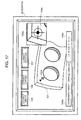
- FIG. 2 shows the workpiece 26 having two cylindrical bores machined at two places therein.
- the contours of the cylindrical bores are referred to as workpiece contours 24a and 24b.
- FIG. 3 shows the workpiece 26 before the cylindrical bore is machined.
- Design data projected on the workpiece 26 is a projection contour 25. In this way, by projecting design data on an actual workpiece prior to machining, a final image of machining can be confirmed on an actual workpiece prior to machining. This is one of the effects of this embodiment.
- FIG. 4 shows the workpiece 26 having therein the cylindrical bore halfway machined.
- FIG. 5 shows a state where a cross line 27 is drawn at a punch mark 28 indicative of a machining position.
- the NC processing machine itself punches prior to processing.
- a machining position in design is projected to the machining punch mark 28, e.g., in the case of cylindrical bore machining, the cross line 27 is projected to the center of a circle, so that it can be determined prior to machining whether or not a machining punch position, i.e., a machining position input to an NC program, coincides with a position indicated by design, and thus wrong cutting, i.e., machining at a different position, can be obviated.
- FIG. 6 shows a state where cross lines 27a and 27b are drawn, respectively, at a start point 28a and an end point 28b of a marking-off line serving as a reference for a machine work, respectively.
- FIG. 7 a specific procedure for detecting a machining remaining amount and a machining positional deviation amount is described.
- an image is captured with the left camera and the right camera while laser drawing is turned off (L1, R1).
- the contour of a workpiece is extracted (L2, R2), stereo matching is performed (LR1) after performing parallax correction (L3, R3), and the three-dimensional coordinate of the workpiece contour is calculated (LR2).
- L1, R1 the contour of a workpiece is extracted
- LR1 stereo matching
- L3, R3 stereo matching
- the three-dimensional coordinate of the workpiece contour is calculated
- an image is captured with the left camera and the right camera (L4, R4).
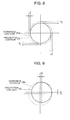
- the remaining amount may be defined as shown in FIG. 8 , for example.
- the machining positional deviation amount may be defined as shown in FIG. 9 .
- FIG. 10 in order to extract an arc contour of a cylindrical bore, processing shown in FIG. 10 may be performed, for example. Specifically, first a captured image ( FIG. 10A ) is binarized ( FIG. 10B ), and subsequently a connected component is calculated ( FIG. 10C ). Specifically, area selection based on a shape feature quantity (in this embodiment, elliptic arc) will be performed. Next, the shape of the selected area is converted to a minimum circumscribed circle ( FIG. 10D ). Furthermore, the area is expanded with a circular structural element ( FIG. 10E ). Note that, in FIG. 10E , only two arcs are expressed, but actually in FIG.
- a shape feature quantity in this embodiment, elliptic arc
- FIG. 10C the areas are finely selected, and therefore actually there are the same number of circular structural elements as the number of the selected areas. Then, a sum area of all areas is calculated ( FIG. 10F ). Then, as shown in FIG. 10G , an area (analysis area) including a desired workpiece contour is narrowed down. Subsequently, within this analysis area, the image is divided by threshold value processing ( FIG. 10H ), and further divided into line segments and elliptic arcs (including arcs) ( FIG. 10I ), and the contours present on the the same circle are connected ( FIG. 10J ).
- processing is performed, in which an ellipse is applied to the divided line segments and arcs, and the one whose center position and radius are within a certain range is regarded as the same circle.
- the image may be displayed on a monitor 29 and when an operator depresses a contour extraction button 107, the above-described contour extraction processing may be performed and an extraction result may be displayed so as to be superimposed on the image.
- a desired contour may be selected with a mouse pointer 102a.
- the laser projection unit can also draw a text, and therefore as shown in FIG. 13 and FIG. 14 , the remaining amount and the deviation amount can be directly drawn on a workpiece so as to be able to visually teach an operator. In this manner, by visually showing the remaining amount and the deviation amount to an operator, not only the design information can be projected on a workpiece using a laser beam, but also comparative determination between design information and a machining result on a workpiece can be easily performed.
- a laser beam is projected to an adequate position on a workpiece ( FIG. 15a ).
- the angles of the first and second galvanomirrors are grasped by the mirror position indication/detection unit 15 ( FIG. 15b ).
- the three-dimensional coordinate of a laser bright spot on the workpiece is measured with the stereo camera 8 ( FIG. 15c ).
- the above-described work (Step 1) is repeated three times.
- the above-described work may be performed four times or more as required.
- a relationship between a coordinate seen from the point of origin of the stereo camera and a coordinate seen from the point of origin of the laser projection unit 9 can be calculated.
- the point of origin of the stereo camera 8 is a lens center of the left camera 6, for example.
- the point of origin of the laser projection unit is a mirror center of the first galvanomirror.
- the center of rotation of the first galvanomirror and the center of rotation of the second galvanomirror deviate from each other, but the detailed description thereof is omitted because a two-angle specified projection method taking into consideration a deviation is formulated in US Patent No. 7,306,339 .
- a first angle ⁇ n and a second angle ⁇ m are specified, and therefore it is not possible to know at which distance a workpiece has been irradiated with a projected laser beam. That is, only with information of a point P1 ( ⁇ 1, ⁇ 1) (r1 is uncertain), a point P2 ( ⁇ 2, ⁇ 2) (r2 is uncertain), and a point P3 ( ⁇ 3, ⁇ 3) (r3 is uncertain), it is not possible to determine where a work surface is.
- ( ⁇ n, ⁇ n, rn) is converted to a rectangular coordinate system.
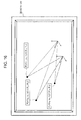
- FIG. 17 and FIG. 18 a specific procedure for calculating the three-dimensional coordinate of a laser bright spot position on the workpiece with the stereo camera 8 is described using FIG. 17 and FIG. 18 .
- an image of the left camera 6 is displayed.
- a reference marker (laser origin) 101 of the workpiece 26 is specified with a mouse pointer 102a
- an enlarged window 103a is displayed.
- a circle extraction button 105 is depressed in advance, the image processing unit 18 will extract a laser bright spot (in a circular form) in an enlarged and displayed area (analysis area) and calculate the center of gravity of the circle.
- the center of gravity position of the circle may be displayed, for example, with a circle, a cross line 104a, and the like.
- the coordinate calculation unit 19 calculates the three-dimensional coordinate of the position of a laser bright spot using a stereo matching approach.
- a calculated coordinate value 108a may be displayed.
- first and second angle values 109a may be displayed.
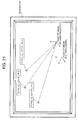
- the analysis area is narrowed down by clicking a vicinity of the reference marker 10a with the mouse, but as shown in FIG. 18 , the analysis area may be narrowed down by drawing a square 110 with the mouse.
- FIG. 17 and FIG. 18 a position serving as a reference on the workpiece, for example such as the three-dimensional coordinate of a feature point, such as a reference marker, and a corner, is described using again FIG. 17 and FIG. 18 , and furthermore FIG. 19 .
- a position serving as a reference on the workpiece for example such as the three-dimensional coordinate of a feature point, such as a reference marker, and a corner.
- an image of the left camera 6 is displayed, for example.
- the circle 101 in FIG. 17 and FIG. 18 is regarded as a reference marker.
- the enlarged window 103a is displayed.
- the image processing unit 18 will extract the reference marker 101 (in a circular form) in an enlarged and displayed area (analysis area) and calculate the center of gravity of the circle.
- the center of gravity position of the circle may be displayed, for example, by a circle, a cross line 104a, and the like.
- the coordinate calculation unit 19 calculates the three-dimensional coordinate of the reference marker using a stereo matching approach. For the calculated three-dimensional coordinate, the calculated coordinate value 108a may be displayed. In addition, the first and second angle values 109a may be displayed.
- a method for example, comprising the steps of: depressing a corner extraction button 106 in advance; selecting a vicinity of the corner with a mouse and thereby automatically recognizing the comer; and calculating the three-dimensional coordinate of the corner.
- a positional relationship between the workpiece 26 and the stereo camera 8 can be calculated. Subsequently, if the recognized positional relationship between the stereo camera 8 and the laser projection unit 9 is used, a positional relationship between the workpiece 26 and the laser projection unit 9 is also uniquely calculated.
- the stage position indication/detection unit 14 and the mirror position indication/detection unit 15 drive the linearly-moving stage 2, the first galvanomirror, and the second galvanomirror via the linearly-moving stage control unit 11, the first angle control unit 12, and the second angle control unit 13 to draw.
- the method and apparatus for laser projection of the present invention are laser projection techniques effectively utilized in order to obviate wrong cutting, confirm processing states, and check omission of machining in machine works.
- FIG. 22 to FIG. 45 a machining method according to an embodiment of the present invention is described using FIG. 22 to FIG. 45 .
- FIG. 22 is a block diagram showing the entire configuration of the working machine for performing the machining method according to an embodiment of the present invention.
- a computer for NC program 32 includes an NC program generation unit 33 and an NC program simulator 34. The details of each of these components will be described later using FIG. 23 .
- a tool taken out from a tool storage unit 310 is assembled.
- a tool image information acquisition unit 312a acquires image information of a tool assembled by the tool assembly unit 311.
- a tool image information determination unit 313a compares the image information acquired by the tool image information acquisition unit 312a with the registered tool image information taken out from the database 31 to determine the tool. The details of the operation of the tool image information acquisition unit 312a and the tool image information determination unit 313a are described later using FIG. 24 .
- a tool measurement unit 37 includes an NC simulator's tool shape data generation unit 8 and a tool-dimension measurement unit 39. The details of each of these components will be described later using FIG. 27 .
- a computer for tool measurement unit 36 prepares a label by a label printer 314, and also prepares a tag by a tag writer 315.
- a tool's label/tag attaching unit 316 attaches the prepared label and tag to a tool.
- a tool information read unit A 317 reads information from the label/tag attached to the tool.
- the tool image information acquisition unit A 312a acquires the image information of the tool.
- a tool image information determination unit B 313b determines the tool from the image information acquired by the tool image information acquisition unit A 312a.
- a comprehensive determination unit A 345a comprehensively determines from the information read by the tool information read unit A 317 and the information acquired by the tool image information determination unit B 313b.
- a comprehensive information generation unit A 346a generates comprehensive information obtained by putting together the information recorded on the label/tag and the image information, and sends the same to the database.
- An NC control working machine (MC) 344 with an ATC includes a machine's X-axis/Y-axis/Z-axis control unit 328, a tool information read unit C 329, a tool image information acquisition unit C 330, an NC control panel 331, a communication terminal unit 332, and an automatic tool change unit (ATC) 318.
- the automatic tool change unit (ATC) 318 includes a tool information read unit B 319, a tool storage unit 320, an ATC arm 321, and an ATC control unit 322.
- the NC control working machine (MC) 344 is controlled by a computer for ATC/MC 347.
- FIG. 23 is a flowchart showing the operation of the computer for NC program used in the working machine that performs the machining method according to an embodiment of the present invention.
- Step S100 In machining a workpiece, first in Step S100, by an NC programmer, an NC program is generated in the NC program generation unit 33 of the computer for NC program 32. Next, in Step S 110, simulation of the NC program to be executed by the working machine 344 is performed by the NC program simulator 34 of the computer for NC program 32, and in Step S120, an error, collision hazard prevention, and the like are checked. An NC program confirmed as not having a problem is stored into the database 31 via a network in Step S130.
- FIG. 24 is a flowchart showing the operation of the tool assembly unit, the tool image information acquisition unit, and the tool image information determination unit used for the working machine that performs the machining method according to an embodiment of the present invention.
- Step S200 a desired tool is selected from the tool storage unit 310 by a working machine's operator. A selected tool is moved to the tool assembly unit 311, and is then assembled by the tool assembly unit 311 in Step S210.
- Step S220 an image of the assembled tool is captured by the tool image information acquisition unit 312a.
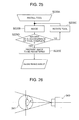
- FIG. 25 to FIG. 30 a method for capturing a tool image for collation in the working machine that performs the machining method according to this embodiment is described.
- FIG. 25 is a flowchart showing the content of the method for capturing a tool image for collation in the working machine that performs the machining method according to an embodiment of the present invention.
- FIG. 26 is an explanatory view of the method for capturing a tool image for collation in the working machine that performs the machining method according to an embodiment of the present invention.
- FIG. 27 to FIG. 30 are front views of various types of tools used for the working machine that performs the machining method according to an embodiment of the present invention.
- Step S220A in FIG. 25 a tool is installed on a turntable.
- Step S220A the tool is imaged.
- FIG. 27 shows an example of the appearance of an end mill.
- FIG. 28 shows an example of the appearance of a radius end mill.
- FIG. 29 shows an example of the appearance of a ball end mill.
- FIG. 30 shows an example of the appearance of a face mill. Even if these tools are of the the same types, the number of cutting edges may differ.
- Step 220D of FIG. 25 the tool is rotated and an image thereof is captured. Then, this is repeated via Step S220C to capture an entire circumference image of the tool, and in Step S220E the captured image is registered with the database 31.
- this embodiment shows an example, in which the entire circumference image of a tool is captured in capturing an image for registration, and when an assembled tool is imaged, an image is captured from one direction and one image captured after assembly is collated with a plurality of registered images.
- Step S240 in the tool image information determination unit 313a, the captured tool image is collated with the registered image. If the both coincide, the collation is complete in Step S260, and if not, collation with the next registered image is performed in Step S250.
- a template matching is used for example.
- an evaluation value indicative of how much a registered image (template) and a captured image are alike.
- T(i, j) a brightness value of a template
- I(i, j) a brightness value of a captured image
- NCC normalized cross-correlation
- a normalized cross-correlation As similarity between a template image and a captured image, a normalized cross-correlation below is used. The closer to 1 the similarity, the more alike the positions become.
- R NCC I 0 ⁇ 0 ⁇ T 0 ⁇ 0 + I 1 ⁇ 0 ⁇ T 1 ⁇ 0 + ⁇ + I ⁇ M - 1 , N - 1 ⁇ T ⁇ M - 1 , N - 1 I ⁇ 0 ⁇ 0 2 + I ⁇ 1 ⁇ 0 2 + ⁇ + I ⁇ M - 1 , N - 1 2 ⁇ T ⁇ 0 ⁇ 0 2 + T ⁇ 1 ⁇ 0 2 + ⁇ + T ⁇ M - 1 , N - 1 2
- the value of RNCC is equivalent to Cos ⁇
- the value of RNCC is a value in a range from -1 to +1.
- ZNCC Zero-mean Normalized Cross-Correlation
- matching may be performed after performing affine transformation (scaling/rotational transform, sharing) to either of the images.
- a mechanism can be constructed, for catching, at this point, a selection error and/or assembly error of a part of a tool caused by a human error and for reliably assembling a desired tool.
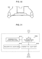
- FIG. 31 is a flowchart showing the operation of the tool measurement unit in the working machine that performs the machining method according to an embodiment of the present invention.
- FIG. 32 to FIG. 35 are explanatory views of shape data of various types of tools used for the working machine that performs the machining method according to an embodiment of the present invention.
- a tool which is assured to be a desired tool by the tool information determination unit A313a of FIG. 22 , is next moved to the tool measurement unit 37.
- Step S310 the NC simulator's tool shape data generation unit 38 sends information ofNC simulator's tool shape data to the database 31 via the computer for tool measurement unit 36.
- the computer for NC program 32 simulates the NC program using this data. Moreover, this information is transferred also to the NC control panel 31.
- FIG. 32 shows an example of the shape data of an end mill.
- the diameter (D) and length (L) of the end mill are measured.
- FIG. 33 shows an example of a radius end mill.
- the diameter (D), length (L), and R of the leading end are measured.
- FIG. 34 shows an example of a ball end mill.
- the diameter (D), length (L), and R of the leading end are measured.
- FIG. 35 shows an example of a face mill, where the diameter (D) and length (L) are measured.
- Step S320 in the NC simulator's tool shape data generation unit 38, the shape of a tool used in the NC program simulator 34 is measured.
- the NC program simulator 34 can simulate based on the shape of a tool that is actually used for machining.
- the shape of the measured tool is sent to the database 31 via the computer for tool measurement unit 36 in Step S330.
- FIG. 36 is a flowchart showing an operation to attach tool information to a tool and confirm the tool in the working machine that performs the machining method according to an embodiment of the present invention.
- FIG. 37 to FIG. 39 are explanatory views indicative of how to attach tool information to a tool in the working machine that performs the machining method according to an embodiment of the present invention.
- FIG. 40 to FIG. 43 are explanatory views indicative of how to confirm a tool in the working machine that performs the machining method according to an embodiment of the present invention.
- Step S400 in FIG. 36 a tool number and tool dimensions (correction values) are printed, by the label printer 314 shown in FIG. 37 , to a label 333 in a matrix type two-dimensional code or the like that can be recognized by an image. Moreover, using a tag writer 315 shown in FIG. 37 , information is written to a tag 334, such as an IC tag, which can be electrically read.
- a tag 334 such as an IC tag
- Step S410 in FIG. 36 by the tool's label/tag attaching unit 316, the tag 334 is attached to tools T310 and T315 as shown in FIG. 37 .
- the label/tag should be attached to the correct tool T310, but here a case is shown where the label/tag is erroneously attached to the tool T315.
- FIG. 38 shows a state where the label 333 is attached to the tool.
- FIG. 39 shows a state where the tag 334 is attached to the tool.
- Step S420 in FIG. 36 the tool information is read by the tool information read unit A317 shown FIG. 22 .
- Step S430 the read tool number and correction data are transferred.
- a label or tag having correct information written thereto is attached to the correct tool as shown in FIG. 40 , and the information will be managed correctly.
- a desired label or tag is attached to the wrong tool (T15), not to a predetermined tool (T10), then as shown in FIG. 41 , wrong information will be associated with the tool.
- Step S430 in FIG. 36 the tool image information acquisition unit B312b images a tool to acquire image information of the tool.
- Step S440 in FIG. 36 a tool having the label/tag attached thereto is determined by a tool information determination unit B (313b) using the image (a tool information determination unit A (313a) may be used via a network). If determined by the image, then as shown in FIG. 42 , a tool having the label/tag currently attached thereto can be determined as the tool (T315).
- Step S450 in FIG. 36 the information read by the tool information read unit A317 and the information determined by the tool image information determination unit B313b are comprehensively determined by the comprehensive determination unit A345a. That is, as shown in FIG. 42 , the tool number read by the tool information read unit A317 is T310 while the tool number determined by the tool image information determination unit B313b is T315 and therefore a disagreement between tools can be detected.
- the comprehensive information generation unit A346a generates comprehensive information by putting together the information recorded on the label/tag and the image information as shown in FIG. 43 and sends the same to the database.
- the label is a matrix type two-dimensional code or the like and the information written thereto can be read by an image
- the information can be read and referred from the image without referring to the information read by the tool information read unit A via the database. That is, a tool number is already recorded on a label and therefore by comparing the read tool number with a tool number determined from the image of an actual tool, whether or not the tool is a desired tool can be determined.
- FIG. 44 is a flowchart showing an operation to store a tool in the working machine that performs the machining method according to an embodiment of the present invention.
- a tool is transported to the NC control working machine (MC) 344 attached with the automatic tool change unit (ATC) 318.
- MC NC control working machine
- ATC automatic tool change unit
- Step S500 tool information is read by the tool information read unit B319. Then, in Step S510, the tool is stored into the tool storage unit 320. Furthermore, in Step S520, information regarding which rack of the tool storage unit 320 the relevant tool has been stored into is sent to the database 31 via the computer for ATC/MC 347. At this time, it is assured that a desired label/tag has been mounted on a desired tool, and therefore here, information regarding what number rack which tool has been stored into may need to be recognized.
- FIG. 45 is a flowchart showing the content of the machining procedure by the working machine that performs the machining method according to an embodiment of the present invention.
- a workpiece 326 is prepared on a table 327.
- Step S600 the operation of the NC control panel 331 is performed by a working machine operator to specify an NC program and the NC program is transferred via a communication terminal 332.
- Step S610 this information is sent to and read into the ATC control unit 322.
- Step S620 based on the read information, the ATC arm 321 selects a desired tool (Tool D, 325) inside the tool storage unit 320, and this tool is mounted on a main shaft 324 in Step S630.
- Step S640 before starting machining, rear information that is supposed to be attached to the main shaft is read by the computer for ATC/MC 347. Moreover, in Step S650, tool information is read by a tool information read unit C329. Then, in Step S660, the information read in Step S640 and the information read in Step S650 are collated. Even if a wrong tool has been selected by ATC318, the tool information read unit C will notice that a wrong tool has been selected. Therefore, wrong cutting will not occur if the machining is stopped at the time when it has been detected that a wrong tool is mounted. However, at an actual machining site, a tool may be manually exchanged without via the ATC. In this case, as already described, only with the information of the tool information read unit C, whether or not a desired tool has been attached to the main shaft 325 cannot be reliably determined.
- the tool information determination unit B313b reads the image information attached to the tool.
- the image information of a tool to be read is the one acquired in advance, and is image information acquired by expanding an image, which is captured by rotating the tool from a position at 0 degree to 360 degrees, from 0 degree to 360 degrees in the rotation direction of the axis of rotation.
- the tool image information acquisition unit C330 images a tool to acquire tool image information. The acquired tool image information is sent to the tool information determination unit B313b via a network.
- Step S690 the tool information determination unit B313b can determine whether or not the tool is a desired tool, by collating the image information of Step S670 with the image information of Step S680.
- the acquisition of the tool image information in Step S680 is performed by either of the following methods.
- the main shaft 324 is not rotated, but at a position when a tool is initially attached to the main shaft 324, an image of the tool in the attached state is captured from one direction.
- Step S690 the 360-degree expanded image information acquired in Step S670 is compared with the image information from one direction to determine whether or not the tool is a desired tool.
- the main shaft 324 is slowly rotated from 0 degree to a predetermined angle (e.g., 90 degrees, 180 degrees, or the like), and an image of a tool in an attached state in a range from 0 degree to a predetermined angle is captured.
- a predetermined angle e.g. 90 degrees, 180 degrees, or the like
- the 360-degree expanded image information acquired in Step S670 is compared with the image information in a range from 0 degree to a predetermined angle to determine whether or not the tool is a desired tool.
- This method can improve the determination accuracy than the first method.
- the main shaft 324 is rotated from 0 degree to 360 degrees, and an image of a tool in an attached state in a range from 0 degree to 360 degrees is captured.
- Step S690 the 360-degree expanded image information acquired in Step S670 is compared with the image information in a range from 0 degree to 360 degrees to determine whether or not the tool is a desired tool.
- This method can improve the determination accuracy than the second method.
- a fourth method while the main shaft 324 is sequentially rotated from 0 degree, an image of a tool in an attached state is captured.
- the 360-degree expanded image information acquired in Step S670 is compared with the image information at each angle acquired while rotating the main shaft 324 from 0 degree, and the rotation is continued until the tool can be determined as a desired tool.
- This method can obtain the determination accuracy nearly equal to the third method, and in addition, can determine in a shorter time than the third method.
- Step S700 a predetermined machining operation is specified by the control unit 328, and X, Y, and Z-axes 323 and the main shaft 324 operate to perform the predetermined machining operation.
Applications Claiming Priority (2)
| Application Number | Priority Date | Filing Date | Title |
|---|---|---|---|
| JP2012260466A JP6114015B2 (ja) | 2012-11-29 | 2012-11-29 | レーザ投影方法およびレーザ投影装置 |
| JP2013040670A JP6106467B2 (ja) | 2013-03-01 | 2013-03-01 | 機械加工方法 |
Publications (3)
| Publication Number | Publication Date |
|---|---|
| EP2738516A2 true EP2738516A2 (fr) | 2014-06-04 |
| EP2738516A3 EP2738516A3 (fr) | 2014-07-09 |
| EP2738516B1 EP2738516B1 (fr) | 2020-04-15 |
Family
ID=49712913
Family Applications (1)
| Application Number | Title | Priority Date | Filing Date |
|---|---|---|---|
| EP13192864.0A Active EP2738516B1 (fr) | 2012-11-29 | 2013-11-14 | Procédé d'usinage |
Country Status (3)
| Country | Link |
|---|---|
| US (2) | US9644942B2 (fr) |
| EP (1) | EP2738516B1 (fr) |
| CN (1) | CN103846739B (fr) |
Cited By (5)
| Publication number | Priority date | Publication date | Assignee | Title |
|---|---|---|---|---|
| GB2536434A (en) * | 2015-03-16 | 2016-09-21 | Sony Corp | A cutting device, cutting equipment and method |
| EP3088129A1 (fr) * | 2015-04-30 | 2016-11-02 | BAE Systems PLC | Inspection de caractéristiques percées dans des objets |
| WO2016174444A1 (fr) * | 2015-04-30 | 2016-11-03 | Bae Systems Plc | Inspection d'éléments percés dans des objets |
| EP3226090A4 (fr) * | 2014-11-26 | 2018-07-25 | Mitsubishi Electric Engineering Company, Limited | Système, dispositif et procédé d'assistance à l'exploitation |
| EP4152277A1 (fr) * | 2021-09-17 | 2023-03-22 | FUJIFILM Business Innovation Corp. | Dispositif, programme et procédé de collation |
Families Citing this family (25)
| Publication number | Priority date | Publication date | Assignee | Title |
|---|---|---|---|---|
| US9026242B2 (en) * | 2011-05-19 | 2015-05-05 | Taktia Llc | Automatically guided tools |
| US10556356B2 (en) | 2012-04-26 | 2020-02-11 | Sharper Tools, Inc. | Systems and methods for performing a task on a material, or locating the position of a device relative to the surface of the material |
| US9491448B2 (en) * | 2013-04-01 | 2016-11-08 | The Boeing Company | Laser videogrammetry |
| CN105934310B (zh) * | 2014-01-24 | 2017-10-27 | 三菱电机株式会社 | 刀具形状测定装置以及刀具形状测定方法 |
| US20150286384A1 (en) * | 2014-04-08 | 2015-10-08 | Quality Vision International, Inc. | Method Of Establishing Multi-Sensor Measuring Machine Routines |
| DE102014213518A1 (de) * | 2014-07-11 | 2016-01-14 | Trumpf Werkzeugmaschinen Gmbh + Co. Kg | Verfahren, Bearbeitungsmaschine und Computerprogrammprodukt zum bildbasierten Platzieren von Werkstückbearbeitungsvorgängen |
| CN104268850B (zh) * | 2014-08-29 | 2017-04-12 | 广东大族粤铭激光集团股份有限公司 | 混合型视觉加工方法 |
| WO2016103125A1 (fr) * | 2014-12-22 | 2016-06-30 | Bombardier Inc. | Système de référence destiné à une inspection de vision en ligne |
| US10037023B2 (en) * | 2015-04-08 | 2018-07-31 | Toyota Motor Engineering & Manufacturing North America, Inc. | Dynamic repair system |
| CN107530878B (zh) | 2015-05-13 | 2021-01-08 | 整形工具股份有限公司 | 用于被引导工具的系统、方法和设备 |
| JP6407812B2 (ja) | 2015-07-14 | 2018-10-17 | ファナック株式会社 | ワーク原点を取得可能な工作機械制御システムおよびワーク原点設定方法 |
| CN105397568A (zh) * | 2015-12-24 | 2016-03-16 | 湖州以创精工机械有限公司 | 一种车床车刀中心高误差的测算方法 |
| US11537099B2 (en) | 2016-08-19 | 2022-12-27 | Sharper Tools, Inc. | Systems, methods and apparatus for sharing tool fabrication and design data |
| JP6496338B2 (ja) * | 2017-03-14 | 2019-04-03 | ファナック株式会社 | 工作機械の制御システム |
| JP6420398B1 (ja) * | 2017-04-07 | 2018-11-07 | ファナック株式会社 | 制御装置、ワイヤ放電加工機、プログラム編集装置および制御方法 |
| JP6474450B2 (ja) | 2017-04-17 | 2019-02-27 | ファナック株式会社 | 工作機械の制御システム |
| JP6514264B2 (ja) | 2017-04-20 | 2019-05-15 | ファナック株式会社 | 工作機械の制御システム |
| CN107179050B (zh) * | 2017-06-13 | 2019-07-16 | 松下压缩机(大连)有限公司 | 零部件斜孔孔位置检测方法 |
| JP6524156B2 (ja) * | 2017-08-07 | 2019-06-05 | 株式会社アマダホールディングス | 情報投影方法及び装置並びにレーザ加工装置 |
| EP3450909A1 (fr) * | 2017-09-05 | 2019-03-06 | Renishaw PLC | Appareil et procédé optiques de réglage d'outil sans contact |
| TWI645933B (zh) * | 2017-12-08 | 2019-01-01 | 財團法人工業技術研究院 | 確認刀具位置之方法與工具機系統 |
| TWI669484B (zh) * | 2018-10-12 | 2019-08-21 | 財團法人工業技術研究院 | 加工程式與對應之切削刀具之匹配辨識方法與系統 |
| WO2021106154A1 (fr) * | 2019-11-28 | 2021-06-03 | 三菱電機株式会社 | Dispositif de recherche d'image de pièce à travailler, procédé de recherche d'image de pièce à travailler et dispositif d'apprentissage automatique |
| JP2021189822A (ja) * | 2020-06-01 | 2021-12-13 | オリンパス株式会社 | 画像処理システム、及び、画像処理方法、並びに、画像処理プログラム |
| CN113744242B (zh) * | 2021-09-03 | 2023-08-15 | 上海柏楚电子科技股份有限公司 | 板材的检测方法、装置、电子设备与存储介质 |
Citations (6)
| Publication number | Priority date | Publication date | Assignee | Title |
|---|---|---|---|---|
| JPH06134638A (ja) | 1992-10-26 | 1994-05-17 | Osaka Kiko Co Ltd | 工具の自動照合認識装置 |
| JPH0661668B2 (ja) | 1985-02-04 | 1994-08-17 | 株式会社アマダ | 工作機械の工具管理システム |
| JP2001269844A (ja) | 2000-03-27 | 2001-10-02 | Toshiba Corp | 工具観察方法とその装置および切削加工システム |
| US6547397B1 (en) | 2000-04-19 | 2003-04-15 | Laser Projection Technologies, Inc. | Apparatus and method for projecting a 3D image |
| JP2005324262A (ja) | 2004-05-12 | 2005-11-24 | Nippei Toyama Corp | 工作機械における工具管理装置 |
| US7306339B2 (en) | 2005-02-01 | 2007-12-11 | Laser Projection Technologies, Inc. | Laser projection with object feature detection |
Family Cites Families (40)
| Publication number | Priority date | Publication date | Assignee | Title |
|---|---|---|---|---|
| JPS6434629A (en) | 1987-07-29 | 1989-02-06 | Toshiba Corp | Control device for modular tool |
| JPH0386447A (ja) * | 1989-08-25 | 1991-04-11 | Fanuc Ltd | ならい制御装置 |
| DE4222804A1 (de) * | 1991-07-10 | 1993-04-01 | Raytheon Co | Einrichtung und verfahren zur automatischen visuellen pruefung elektrischer und elektronischer baueinheiten |
| US5331275A (en) * | 1991-12-09 | 1994-07-19 | Fujitsu Limited | Probing device and system for testing an integrated circuit |
| WO1994002284A1 (fr) | 1992-07-28 | 1994-02-03 | Tulon Co. | Procede et appareil de gestion d'outils |
| US5450147A (en) * | 1992-09-28 | 1995-09-12 | The Boeing Company | Method for controlling projection of optical layup template utilizing cooperative targets |
| EP0683389A1 (fr) * | 1994-05-12 | 1995-11-22 | Kabushiki Kaisha Toshiba | Tomographe à laminographie et dispositif d'inspection et de réparation utilisant un tel tomographe |
| JP3347522B2 (ja) * | 1995-04-11 | 2002-11-20 | キヤノン株式会社 | 工具経路作成装置及び工具経路作成方法 |
| US5721587A (en) * | 1995-07-07 | 1998-02-24 | Amada Mfg America Inc. | Method and apparatus for inspecting product processed by turret punch press machine |
| JPH0985584A (ja) | 1995-09-20 | 1997-03-31 | Toshiba Mach Co Ltd | ツールの許容運動速度検出方法および装置およびプログラム機械装置における使用ツール対応運動速度確認方法および装置 |
| US5963662A (en) * | 1996-08-07 | 1999-10-05 | Georgia Tech Research Corporation | Inspection system and method for bond detection and validation of surface mount devices |
| TW323685U (en) * | 1997-05-07 | 1997-12-21 | qing-hui Chen | Frame structure allowing easily replacing aluminum doors and windows |
| JP3970386B2 (ja) * | 1997-06-24 | 2007-09-05 | 株式会社アマダ | パンチプレス用自動プログラミング装置、及びそのプログラムを記憶した記録媒体 |
| WO1999026099A1 (fr) | 1997-11-14 | 1999-05-27 | Virtek Vision Corporation | Procede et systeme de balayage laser |
| US6556307B1 (en) * | 1998-09-11 | 2003-04-29 | Minolta Co., Ltd. | Method and apparatus for inputting three-dimensional data |
| DE10000491B4 (de) * | 2000-01-08 | 2004-09-23 | Kelch Gmbh + Co Werkzeugmaschinenfabrik | Verfahren und Messeinrichtung zum Vermessen eines Rotationswerkzeuges |
| JP4032603B2 (ja) * | 2000-03-31 | 2008-01-16 | コニカミノルタセンシング株式会社 | 3次元計測装置 |
| US7127098B2 (en) * | 2001-09-13 | 2006-10-24 | Hitachi, Ltd. | Image detection method and its apparatus and defect detection method and its apparatus |
| US6809801B2 (en) * | 2002-03-11 | 2004-10-26 | Sharp Laboratories Of America, Inc. | 1:1 projection system and method for laser irradiating semiconductor films |
| JP2004046772A (ja) * | 2002-05-13 | 2004-02-12 | 3D Media Co Ltd | 画像処理方法、画像処理システム、及び画像処理装置 |
| JP4183492B2 (ja) * | 2002-11-27 | 2008-11-19 | 株式会社日立製作所 | 欠陥検査装置および欠陥検査方法 |
| JP4480488B2 (ja) * | 2003-08-28 | 2010-06-16 | 富士通株式会社 | 計測装置、コンピュータ数値制御装置及びプログラム |
| JP4147169B2 (ja) * | 2003-10-17 | 2008-09-10 | 日立ビアメカニクス株式会社 | バンプ形状計測装置及びその方法 |
| US7715619B2 (en) * | 2003-10-21 | 2010-05-11 | Nec Corporation | Image collation system and image collation method |
| US7241981B2 (en) * | 2004-03-05 | 2007-07-10 | Lap Laser Llc | Systems and methods for displaying images and processing work pieces |
| US7701592B2 (en) * | 2004-12-17 | 2010-04-20 | The Boeing Company | Method and apparatus for combining a targetless optical measurement function and optical projection of information |
| US8085388B2 (en) * | 2005-02-01 | 2011-12-27 | Laser Projection Technologies, Inc. | Laser radar projection with object feature detection and ranging |
| US7454841B2 (en) | 2005-11-01 | 2008-11-25 | Hunter Engineering Company | Method and apparatus for wheel alignment system target projection and illumination |
| TWI364889B (en) * | 2005-11-11 | 2012-05-21 | Hon Hai Prec Ind Co Ltd | Laser device and laser system using the same |
| TW200841981A (en) * | 2007-04-20 | 2008-11-01 | Univ Nat Formosa | Laser array measurement system for testing three dimensional positioning performance, measuring three dimensional orbit and straightness of arbitrary axis |
| EP2163847B1 (fr) | 2007-06-15 | 2013-10-16 | Kabushiki Kaisha Toshiba | Instrument permettant d'examiner/de mesurer un objet qui doit être mesuré |
| JP5315756B2 (ja) * | 2008-04-01 | 2013-10-16 | セイコーエプソン株式会社 | 画像表示装置 |
| JP5452973B2 (ja) * | 2009-04-28 | 2014-03-26 | 富士機械製造株式会社 | 撮像装置及びその撮像装置を備える切削機械 |
| JP5602392B2 (ja) * | 2009-06-25 | 2014-10-08 | キヤノン株式会社 | 情報処理装置、情報処理方法およびプログラム |
| US8269970B2 (en) * | 2009-07-02 | 2012-09-18 | Quality Vision International, Inc. | Optical comparator with digital gage |
| US8118438B2 (en) * | 2009-07-24 | 2012-02-21 | Optimet, Optical Metrology Ltd. | Method and apparatus for real-time projection onto an object of data obtained from 3-D measurement |
| DE102009045298A1 (de) | 2009-10-02 | 2011-04-07 | Traub Drehmaschinen Gmbh & Co. Kg | Optisches Assistenzsystem für Werkzeugmaschinen |
| CN201637937U (zh) * | 2010-01-21 | 2010-11-17 | 广景科技有限公司 | 一种新型的三维投影装置 |
| JP2013539541A (ja) | 2010-09-08 | 2013-10-24 | ファロ テクノロジーズ インコーポレーテッド | プロジェクタを有するレーザスキャナまたはレーザ追跡装置 |
| JP5440548B2 (ja) * | 2011-04-28 | 2014-03-12 | カシオ計算機株式会社 | 投影装置、投影方法及びプログラム |
-
2013
- 2013-11-13 US US14/079,515 patent/US9644942B2/en active Active
- 2013-11-14 EP EP13192864.0A patent/EP2738516B1/fr active Active
- 2013-11-14 CN CN201310566097.8A patent/CN103846739B/zh active Active
-
2016
- 2016-05-27 US US15/166,394 patent/US10094652B2/en active Active
Patent Citations (6)
| Publication number | Priority date | Publication date | Assignee | Title |
|---|---|---|---|---|
| JPH0661668B2 (ja) | 1985-02-04 | 1994-08-17 | 株式会社アマダ | 工作機械の工具管理システム |
| JPH06134638A (ja) | 1992-10-26 | 1994-05-17 | Osaka Kiko Co Ltd | 工具の自動照合認識装置 |
| JP2001269844A (ja) | 2000-03-27 | 2001-10-02 | Toshiba Corp | 工具観察方法とその装置および切削加工システム |
| US6547397B1 (en) | 2000-04-19 | 2003-04-15 | Laser Projection Technologies, Inc. | Apparatus and method for projecting a 3D image |
| JP2005324262A (ja) | 2004-05-12 | 2005-11-24 | Nippei Toyama Corp | 工作機械における工具管理装置 |
| US7306339B2 (en) | 2005-02-01 | 2007-12-11 | Laser Projection Technologies, Inc. | Laser projection with object feature detection |
Cited By (6)
| Publication number | Priority date | Publication date | Assignee | Title |
|---|---|---|---|---|
| EP3226090A4 (fr) * | 2014-11-26 | 2018-07-25 | Mitsubishi Electric Engineering Company, Limited | Système, dispositif et procédé d'assistance à l'exploitation |
| GB2536434A (en) * | 2015-03-16 | 2016-09-21 | Sony Corp | A cutting device, cutting equipment and method |
| EP3088129A1 (fr) * | 2015-04-30 | 2016-11-02 | BAE Systems PLC | Inspection de caractéristiques percées dans des objets |
| WO2016174444A1 (fr) * | 2015-04-30 | 2016-11-03 | Bae Systems Plc | Inspection d'éléments percés dans des objets |
| US10399199B2 (en) | 2015-04-30 | 2019-09-03 | Bae Systems Plc | Inspection of drilled features in objects |
| EP4152277A1 (fr) * | 2021-09-17 | 2023-03-22 | FUJIFILM Business Innovation Corp. | Dispositif, programme et procédé de collation |
Also Published As
| Publication number | Publication date |
|---|---|
| US9644942B2 (en) | 2017-05-09 |
| EP2738516A3 (fr) | 2014-07-09 |
| US20160273905A1 (en) | 2016-09-22 |
| EP2738516B1 (fr) | 2020-04-15 |
| US10094652B2 (en) | 2018-10-09 |
| CN103846739B (zh) | 2016-10-19 |
| CN103846739A (zh) | 2014-06-11 |
| US20140148939A1 (en) | 2014-05-29 |
Similar Documents
| Publication | Publication Date | Title |
|---|---|---|
| US10094652B2 (en) | Method and apparatus for laser projection, and machining method | |
| JP6106467B2 (ja) | 機械加工方法 | |
| US20180350055A1 (en) | Augmented reality feature detection | |
| JP3596753B2 (ja) | 画像測定装置用パートプログラム生成装置及び方法 | |
| US11731283B2 (en) | Method for checking a safety area of a robot | |
| CN107727485B (zh) | 用于硬度测试的方法和装置 | |
| JP2008235504A (ja) | 組立品検査装置 | |
| JP2021121461A (ja) | 画像処理装置 | |
| US20230214083A1 (en) | Measurement program selection assisting apparatus and measurement control apparatus | |
| JP2010042466A (ja) | ロボット教示システム及びロボットの動作のシミュレーション結果の表示方法 | |
| US20190047106A1 (en) | Method for determining an x-y-z reference coordinate of a workpiece, and machine tool | |
| WO2018223038A1 (fr) | Application de réalité augmentée pour la fabrication | |
| CN109862989B (zh) | 激光焊接时的基于图像的技术选择 | |
| Ng et al. | Intuitive robot tool path teaching using laser and camera in augmented reality environment | |
| CN114355953A (zh) | 一种基于机器视觉的多轴伺服系统的高精度控制方法及系统 | |
| CN113319859B (zh) | 一种机器人示教方法、系统、装置及电子设备 | |
| JP6114015B2 (ja) | レーザ投影方法およびレーザ投影装置 | |
| CN114074321A (zh) | 机器人标定方法及装置 | |
| US11630436B2 (en) | Measurement program selection assisting apparatus and measurement control apparatus | |
| CN111462341A (zh) | 增强现实的建造辅助方法、装置、终端和介质 | |
| US11826908B2 (en) | Process agnostic robot teaching using 3D scans | |
| Traband et al. | CAD-directed Programming of a Vision-based Inspection System | |
| JP6857052B2 (ja) | ロボット設定装置、ロボット設定方法、ロボット設定プログラム及びコンピュータで読み取り可能な記録媒体並びに記録した機器 | |
| CN117132528A (zh) | 焊接部位的检查系统 | |
| CN115752238A (zh) | 双目十字激光精准定位系统及方法 |
Legal Events
| Date | Code | Title | Description |
|---|---|---|---|
| PUAI | Public reference made under article 153(3) epc to a published international application that has entered the european phase |
Free format text: ORIGINAL CODE: 0009012 |
|
| 17P | Request for examination filed |
Effective date: 20131213 |
|
| AK | Designated contracting states |
Kind code of ref document: A2 Designated state(s): AL AT BE BG CH CY CZ DE DK EE ES FI FR GB GR HR HU IE IS IT LI LT LU LV MC MK MT NL NO PL PT RO RS SE SI SK SM TR |
|
| AX | Request for extension of the european patent |
Extension state: BA ME |
|
| PUAL | Search report despatched |
Free format text: ORIGINAL CODE: 0009013 |
|
| AK | Designated contracting states |
Kind code of ref document: A3 Designated state(s): AL AT BE BG CH CY CZ DE DK EE ES FI FR GB GR HR HU IE IS IT LI LT LU LV MC MK MT NL NO PL PT RO RS SE SI SK SM TR |
|
| AX | Request for extension of the european patent |
Extension state: BA ME |
|
| RIC1 | Information provided on ipc code assigned before grant |
Ipc: B23Q 3/155 20060101ALI20140603BHEP Ipc: G01B 11/25 20060101AFI20140603BHEP Ipc: B23Q 17/24 20060101ALI20140603BHEP Ipc: G05B 19/4093 20060101ALI20140603BHEP |
|
| RAP1 | Party data changed (applicant data changed or rights of an application transferred) |
Owner name: MITSUBISHI HITACHI POWER SYSTEMS, LTD. |
|
| RAP1 | Party data changed (applicant data changed or rights of an application transferred) |
Owner name: MITSUBISHI HITACHI POWER SYSTEMS, LTD. |
|
| STAA | Information on the status of an ep patent application or granted ep patent |
Free format text: STATUS: EXAMINATION IS IN PROGRESS |
|
| 17Q | First examination report despatched |
Effective date: 20180921 |
|
| RIC1 | Information provided on ipc code assigned before grant |
Ipc: G05B 19/4097 20060101ALI20190911BHEP Ipc: B23Q 17/24 20060101ALI20190911BHEP Ipc: G01B 11/25 20060101AFI20190911BHEP Ipc: G05B 19/401 20060101ALI20190911BHEP Ipc: B23Q 17/22 20060101ALI20190911BHEP |
|
| GRAP | Despatch of communication of intention to grant a patent |
Free format text: ORIGINAL CODE: EPIDOSNIGR1 |
|
| STAA | Information on the status of an ep patent application or granted ep patent |
Free format text: STATUS: GRANT OF PATENT IS INTENDED |
|
| INTG | Intention to grant announced |
Effective date: 20191029 |
|
| GRAS | Grant fee paid |
Free format text: ORIGINAL CODE: EPIDOSNIGR3 |
|
| GRAA | (expected) grant |
Free format text: ORIGINAL CODE: 0009210 |
|
| STAA | Information on the status of an ep patent application or granted ep patent |
Free format text: STATUS: THE PATENT HAS BEEN GRANTED |
|
| AK | Designated contracting states |
Kind code of ref document: B1 Designated state(s): AL AT BE BG CH CY CZ DE DK EE ES FI FR GB GR HR HU IE IS IT LI LT LU LV MC MK MT NL NO PL PT RO RS SE SI SK SM TR |
|
| REG | Reference to a national code |
Ref country code: CH Ref legal event code: EP Ref country code: GB Ref legal event code: FG4D |
|
| REG | Reference to a national code |
Ref country code: DE Ref legal event code: R096 Ref document number: 602013067885 Country of ref document: DE |
|
| REG | Reference to a national code |
Ref country code: IE Ref legal event code: FG4D |
|
| REG | Reference to a national code |
Ref country code: AT Ref legal event code: REF Ref document number: 1257838 Country of ref document: AT Kind code of ref document: T Effective date: 20200515 |
|
| REG | Reference to a national code |
Ref country code: NL Ref legal event code: MP Effective date: 20200415 |
|
| REG | Reference to a national code |
Ref country code: LT Ref legal event code: MG4D |
|
| PG25 | Lapsed in a contracting state [announced via postgrant information from national office to epo] |
Ref country code: GR Free format text: LAPSE BECAUSE OF FAILURE TO SUBMIT A TRANSLATION OF THE DESCRIPTION OR TO PAY THE FEE WITHIN THE PRESCRIBED TIME-LIMIT Effective date: 20200716 Ref country code: FI Free format text: LAPSE BECAUSE OF FAILURE TO SUBMIT A TRANSLATION OF THE DESCRIPTION OR TO PAY THE FEE WITHIN THE PRESCRIBED TIME-LIMIT Effective date: 20200415 Ref country code: LT Free format text: LAPSE BECAUSE OF FAILURE TO SUBMIT A TRANSLATION OF THE DESCRIPTION OR TO PAY THE FEE WITHIN THE PRESCRIBED TIME-LIMIT Effective date: 20200415 Ref country code: SE Free format text: LAPSE BECAUSE OF FAILURE TO SUBMIT A TRANSLATION OF THE DESCRIPTION OR TO PAY THE FEE WITHIN THE PRESCRIBED TIME-LIMIT Effective date: 20200415 Ref country code: IS Free format text: LAPSE BECAUSE OF FAILURE TO SUBMIT A TRANSLATION OF THE DESCRIPTION OR TO PAY THE FEE WITHIN THE PRESCRIBED TIME-LIMIT Effective date: 20200815 Ref country code: NO Free format text: LAPSE BECAUSE OF FAILURE TO SUBMIT A TRANSLATION OF THE DESCRIPTION OR TO PAY THE FEE WITHIN THE PRESCRIBED TIME-LIMIT Effective date: 20200715 Ref country code: NL Free format text: LAPSE BECAUSE OF FAILURE TO SUBMIT A TRANSLATION OF THE DESCRIPTION OR TO PAY THE FEE WITHIN THE PRESCRIBED TIME-LIMIT Effective date: 20200415 Ref country code: PT Free format text: LAPSE BECAUSE OF FAILURE TO SUBMIT A TRANSLATION OF THE DESCRIPTION OR TO PAY THE FEE WITHIN THE PRESCRIBED TIME-LIMIT Effective date: 20200817 |
|
| REG | Reference to a national code |
Ref country code: AT Ref legal event code: MK05 Ref document number: 1257838 Country of ref document: AT Kind code of ref document: T Effective date: 20200415 |
|
| PG25 | Lapsed in a contracting state [announced via postgrant information from national office to epo] |
Ref country code: HR Free format text: LAPSE BECAUSE OF FAILURE TO SUBMIT A TRANSLATION OF THE DESCRIPTION OR TO PAY THE FEE WITHIN THE PRESCRIBED TIME-LIMIT Effective date: 20200415 Ref country code: RS Free format text: LAPSE BECAUSE OF FAILURE TO SUBMIT A TRANSLATION OF THE DESCRIPTION OR TO PAY THE FEE WITHIN THE PRESCRIBED TIME-LIMIT Effective date: 20200415 Ref country code: BG Free format text: LAPSE BECAUSE OF FAILURE TO SUBMIT A TRANSLATION OF THE DESCRIPTION OR TO PAY THE FEE WITHIN THE PRESCRIBED TIME-LIMIT Effective date: 20200715 Ref country code: LV Free format text: LAPSE BECAUSE OF FAILURE TO SUBMIT A TRANSLATION OF THE DESCRIPTION OR TO PAY THE FEE WITHIN THE PRESCRIBED TIME-LIMIT Effective date: 20200415 |
|
| REG | Reference to a national code |
Ref country code: DE Ref legal event code: R082 Ref document number: 602013067885 Country of ref document: DE Representative=s name: MERH-IP MATIAS ERNY REICHL HOFFMANN PATENTANWA, DE Ref country code: DE Ref legal event code: R081 Ref document number: 602013067885 Country of ref document: DE Owner name: MITSUBISHI POWER, LTD., JP Free format text: FORMER OWNER: MITSUBISHI HITACHI POWER SYSTEMS, LTD., YOKOHAMA, JP |
|
| PG25 | Lapsed in a contracting state [announced via postgrant information from national office to epo] |
Ref country code: AL Free format text: LAPSE BECAUSE OF FAILURE TO SUBMIT A TRANSLATION OF THE DESCRIPTION OR TO PAY THE FEE WITHIN THE PRESCRIBED TIME-LIMIT Effective date: 20200415 |
|
| REG | Reference to a national code |
Ref country code: DE Ref legal event code: R097 Ref document number: 602013067885 Country of ref document: DE |
|
| PG25 | Lapsed in a contracting state [announced via postgrant information from national office to epo] |
Ref country code: ES Free format text: LAPSE BECAUSE OF FAILURE TO SUBMIT A TRANSLATION OF THE DESCRIPTION OR TO PAY THE FEE WITHIN THE PRESCRIBED TIME-LIMIT Effective date: 20200415 Ref country code: DK Free format text: LAPSE BECAUSE OF FAILURE TO SUBMIT A TRANSLATION OF THE DESCRIPTION OR TO PAY THE FEE WITHIN THE PRESCRIBED TIME-LIMIT Effective date: 20200415 Ref country code: EE Free format text: LAPSE BECAUSE OF FAILURE TO SUBMIT A TRANSLATION OF THE DESCRIPTION OR TO PAY THE FEE WITHIN THE PRESCRIBED TIME-LIMIT Effective date: 20200415 Ref country code: SM Free format text: LAPSE BECAUSE OF FAILURE TO SUBMIT A TRANSLATION OF THE DESCRIPTION OR TO PAY THE FEE WITHIN THE PRESCRIBED TIME-LIMIT Effective date: 20200415 Ref country code: IT Free format text: LAPSE BECAUSE OF FAILURE TO SUBMIT A TRANSLATION OF THE DESCRIPTION OR TO PAY THE FEE WITHIN THE PRESCRIBED TIME-LIMIT Effective date: 20200415 Ref country code: CZ Free format text: LAPSE BECAUSE OF FAILURE TO SUBMIT A TRANSLATION OF THE DESCRIPTION OR TO PAY THE FEE WITHIN THE PRESCRIBED TIME-LIMIT Effective date: 20200415 Ref country code: AT Free format text: LAPSE BECAUSE OF FAILURE TO SUBMIT A TRANSLATION OF THE DESCRIPTION OR TO PAY THE FEE WITHIN THE PRESCRIBED TIME-LIMIT Effective date: 20200415 Ref country code: RO Free format text: LAPSE BECAUSE OF FAILURE TO SUBMIT A TRANSLATION OF THE DESCRIPTION OR TO PAY THE FEE WITHIN THE PRESCRIBED TIME-LIMIT Effective date: 20200415 |
|
| PLBE | No opposition filed within time limit |
Free format text: ORIGINAL CODE: 0009261 |
|
| STAA | Information on the status of an ep patent application or granted ep patent |
Free format text: STATUS: NO OPPOSITION FILED WITHIN TIME LIMIT |
|
| PG25 | Lapsed in a contracting state [announced via postgrant information from national office to epo] |
Ref country code: PL Free format text: LAPSE BECAUSE OF FAILURE TO SUBMIT A TRANSLATION OF THE DESCRIPTION OR TO PAY THE FEE WITHIN THE PRESCRIBED TIME-LIMIT Effective date: 20200415 Ref country code: SK Free format text: LAPSE BECAUSE OF FAILURE TO SUBMIT A TRANSLATION OF THE DESCRIPTION OR TO PAY THE FEE WITHIN THE PRESCRIBED TIME-LIMIT Effective date: 20200415 |
|
| 26N | No opposition filed |
Effective date: 20210118 |
|
| PG25 | Lapsed in a contracting state [announced via postgrant information from national office to epo] |
Ref country code: SI Free format text: LAPSE BECAUSE OF FAILURE TO SUBMIT A TRANSLATION OF THE DESCRIPTION OR TO PAY THE FEE WITHIN THE PRESCRIBED TIME-LIMIT Effective date: 20200415 |
|
| PG25 | Lapsed in a contracting state [announced via postgrant information from national office to epo] |
Ref country code: MC Free format text: LAPSE BECAUSE OF FAILURE TO SUBMIT A TRANSLATION OF THE DESCRIPTION OR TO PAY THE FEE WITHIN THE PRESCRIBED TIME-LIMIT Effective date: 20200415 |
|
| REG | Reference to a national code |
Ref country code: CH Ref legal event code: PL |
|
| GBPC | Gb: european patent ceased through non-payment of renewal fee |
Effective date: 20201114 |
|
| PG25 | Lapsed in a contracting state [announced via postgrant information from national office to epo] |
Ref country code: LU Free format text: LAPSE BECAUSE OF NON-PAYMENT OF DUE FEES Effective date: 20201114 |
|
| REG | Reference to a national code |
Ref country code: BE Ref legal event code: MM Effective date: 20201130 |
|
| PG25 | Lapsed in a contracting state [announced via postgrant information from national office to epo] |
Ref country code: CH Free format text: LAPSE BECAUSE OF NON-PAYMENT OF DUE FEES Effective date: 20201130 Ref country code: LI Free format text: LAPSE BECAUSE OF NON-PAYMENT OF DUE FEES Effective date: 20201130 |
|
| PG25 | Lapsed in a contracting state [announced via postgrant information from national office to epo] |
Ref country code: IE Free format text: LAPSE BECAUSE OF NON-PAYMENT OF DUE FEES Effective date: 20201114 Ref country code: FR Free format text: LAPSE BECAUSE OF NON-PAYMENT OF DUE FEES Effective date: 20201130 |
|
| PG25 | Lapsed in a contracting state [announced via postgrant information from national office to epo] |
Ref country code: GB Free format text: LAPSE BECAUSE OF NON-PAYMENT OF DUE FEES Effective date: 20201114 |
|
| PG25 | Lapsed in a contracting state [announced via postgrant information from national office to epo] |
Ref country code: TR Free format text: LAPSE BECAUSE OF FAILURE TO SUBMIT A TRANSLATION OF THE DESCRIPTION OR TO PAY THE FEE WITHIN THE PRESCRIBED TIME-LIMIT Effective date: 20200415 Ref country code: MT Free format text: LAPSE BECAUSE OF FAILURE TO SUBMIT A TRANSLATION OF THE DESCRIPTION OR TO PAY THE FEE WITHIN THE PRESCRIBED TIME-LIMIT Effective date: 20200415 Ref country code: CY Free format text: LAPSE BECAUSE OF FAILURE TO SUBMIT A TRANSLATION OF THE DESCRIPTION OR TO PAY THE FEE WITHIN THE PRESCRIBED TIME-LIMIT Effective date: 20200415 |
|
| PG25 | Lapsed in a contracting state [announced via postgrant information from national office to epo] |
Ref country code: MK Free format text: LAPSE BECAUSE OF FAILURE TO SUBMIT A TRANSLATION OF THE DESCRIPTION OR TO PAY THE FEE WITHIN THE PRESCRIBED TIME-LIMIT Effective date: 20200415 |
|
| PG25 | Lapsed in a contracting state [announced via postgrant information from national office to epo] |
Ref country code: BE Free format text: LAPSE BECAUSE OF NON-PAYMENT OF DUE FEES Effective date: 20201130 |
|
| PGFP | Annual fee paid to national office [announced via postgrant information from national office to epo] |
Ref country code: DE Payment date: 20220621 Year of fee payment: 10 |