EP2735843A1 - Messmaschine und Verfahren zur automatischen Messung eines Objekts - Google Patents
Messmaschine und Verfahren zur automatischen Messung eines Objekts Download PDFInfo
- Publication number
- EP2735843A1 EP2735843A1 EP12193541.5A EP12193541A EP2735843A1 EP 2735843 A1 EP2735843 A1 EP 2735843A1 EP 12193541 A EP12193541 A EP 12193541A EP 2735843 A1 EP2735843 A1 EP 2735843A1
- Authority
- EP
- European Patent Office
- Prior art keywords
- measuring machine
- measurement
- feature
- measuring
- operator
- Prior art date
- Legal status (The legal status is an assumption and is not a legal conclusion. Google has not performed a legal analysis and makes no representation as to the accuracy of the status listed.)
- Withdrawn
Links
Images


Classifications
-
- G—PHYSICS
- G01—MEASURING; TESTING
- G01B—MEASURING LENGTH, THICKNESS OR SIMILAR LINEAR DIMENSIONS; MEASURING ANGLES; MEASURING AREAS; MEASURING IRREGULARITIES OF SURFACES OR CONTOURS
- G01B5/00—Measuring arrangements characterised by the use of mechanical techniques
- G01B5/004—Measuring arrangements characterised by the use of mechanical techniques for measuring coordinates of points
- G01B5/008—Measuring arrangements characterised by the use of mechanical techniques for measuring coordinates of points using coordinate measuring machines
-
- G—PHYSICS
- G01—MEASURING; TESTING
- G01B—MEASURING LENGTH, THICKNESS OR SIMILAR LINEAR DIMENSIONS; MEASURING ANGLES; MEASURING AREAS; MEASURING IRREGULARITIES OF SURFACES OR CONTOURS
- G01B21/00—Measuring arrangements or details thereof, where the measuring technique is not covered by the other groups of this subclass, unspecified or not relevant
- G01B21/02—Measuring arrangements or details thereof, where the measuring technique is not covered by the other groups of this subclass, unspecified or not relevant for measuring length, width, or thickness
- G01B21/04—Measuring arrangements or details thereof, where the measuring technique is not covered by the other groups of this subclass, unspecified or not relevant for measuring length, width, or thickness by measuring coordinates of points
-
- G—PHYSICS
- G05—CONTROLLING; REGULATING
- G05B—CONTROL OR REGULATING SYSTEMS IN GENERAL; FUNCTIONAL ELEMENTS OF SUCH SYSTEMS; MONITORING OR TESTING ARRANGEMENTS FOR SUCH SYSTEMS OR ELEMENTS
- G05B19/00—Programme-control systems
- G05B19/02—Programme-control systems electric
- G05B19/18—Numerical control [NC], i.e. automatically operating machines, in particular machine tools, e.g. in a manufacturing environment, so as to execute positioning, movement or co-ordinated operations by means of programme data in numerical form
- G05B19/401—Numerical control [NC], i.e. automatically operating machines, in particular machine tools, e.g. in a manufacturing environment, so as to execute positioning, movement or co-ordinated operations by means of programme data in numerical form characterised by control arrangements for measuring, e.g. calibration and initialisation, measuring workpiece for machining purposes
-
- G—PHYSICS
- G05—CONTROLLING; REGULATING
- G05B—CONTROL OR REGULATING SYSTEMS IN GENERAL; FUNCTIONAL ELEMENTS OF SUCH SYSTEMS; MONITORING OR TESTING ARRANGEMENTS FOR SUCH SYSTEMS OR ELEMENTS
- G05B2219/00—Program-control systems
- G05B2219/30—Nc systems
- G05B2219/37—Measurements
- G05B2219/37193—Multicoordinate measuring system, machine, cmm
-
- G—PHYSICS
- G05—CONTROLLING; REGULATING
- G05B—CONTROL OR REGULATING SYSTEMS IN GENERAL; FUNCTIONAL ELEMENTS OF SUCH SYSTEMS; MONITORING OR TESTING ARRANGEMENTS FOR SUCH SYSTEMS OR ELEMENTS
- G05B2219/00—Program-control systems
- G05B2219/30—Nc systems
- G05B2219/37—Measurements
- G05B2219/37443—Program cmm, coordinate measuring machine, use cad data
-
- Y—GENERAL TAGGING OF NEW TECHNOLOGICAL DEVELOPMENTS; GENERAL TAGGING OF CROSS-SECTIONAL TECHNOLOGIES SPANNING OVER SEVERAL SECTIONS OF THE IPC; TECHNICAL SUBJECTS COVERED BY FORMER USPC CROSS-REFERENCE ART COLLECTIONS [XRACs] AND DIGESTS
- Y02—TECHNOLOGIES OR APPLICATIONS FOR MITIGATION OR ADAPTATION AGAINST CLIMATE CHANGE
- Y02P—CLIMATE CHANGE MITIGATION TECHNOLOGIES IN THE PRODUCTION OR PROCESSING OF GOODS
- Y02P90/00—Enabling technologies with a potential contribution to greenhouse gas [GHG] emissions mitigation
- Y02P90/02—Total factory control, e.g. smart factories, flexible manufacturing systems [FMS] or integrated manufacturing systems [IMS]
Definitions
- the present invention relates to a measuring machine, particularly a coordinate measuring machine (CMM), and a method for automated measurement of an object and detection of differences between a feature of the object and computer-aided design (CAD) data of the object, the CAD data being stored in a data base.
- the measuring machine comprises a probe head supported for movement along three mutually perpendicular axes, a probe system comprising a probe to be connected with the probe head, and measurement functionality for determining three-dimensional coordinates of a feature of the object.
- the measuring machine further comprises a local computer terminal that is connected to or part of the measuring machine, an assigned memory unit for storing the data base comprising the CAD data, and an assigned set of measurement software programmes for controlling the measuring machine.
- the probe head is supported for movement along three mutually perpendicular axes (in directions X, Y and 2).
- the probe head comprises a suitable transducer as a probe, for example for tactile or optical measurements, which is used to determine the position of the probe head relative to a base of the machine and to determine the coordinates of a measurement point on an object being approached by the probe.
- the functionality of a conventional coordinate measuring machine is typically structured as follows:
- a conventional process for measuring an object with a measuring machine is structured as follows:
- the execution phase of a conventional measurement process comprises the following steps:
- DE 101 30 737 B4 discloses a system wherein a number of stations are used to measure and adjust cutting tools used on computer numerical control (CNC) machines.
- the units have measuring systems, controlled axes and are linked to local controllers that use local and remote software.
- the remote software is provided by a link over the internet to a central computer.
- the invention of DE 101 30 737 B4 is dedicated to solve the object of providing an adjustment device capable of performing a plurality of different measurement tasks in a flexible way and at low costs.
- a part of the system software is not resident on a local computer for device control, but on an external, central computer, thus reducing the requirements on the local control system.
- a user may be provided with remote software packages for measuring machines via the internet either for sale or for rent, or on any other basis, just only for the time when such "additional intelligence" is needed, this software being saved on and available from an external server.
- JP 9 178 469 discloses a roundness measuring machine provided with an automatic part programme selection, wherein the part programme, in which a measurement procedure for a work piece is incorporated, is selected after a preceding measurement for a discrimination of a work piece fixing jig, e. g. in the form of a hole for identification purposes. In this way, risks of a damage of the measurement tool or part provoked by the potential of a wrong choice of the measurement tool or part are reduced.
- the part programme is selected depending on the size and the position, in an X-Y direction, of the hole as a jig discriminating formation part.
- the invention of JP 9 178 469 does not provide further support for the steps of preparation of a measurement.
- This object is solved by a measuring machine, particularly a coordinate measuring machine, according to claim 1, and a method, according to claim 8, for automated measurement of an object and detection of differences between a feature of the object and CAD data of the object, the CAD data being stored in a data base.
- the measuring machine comprises a probe head, a probe system comprising a probe to be connected with the probe head and measurement functionality for determining three-dimensional coordinates of a feature of the object.
- the measuring machine further comprises a local computer terminal that is connected to or part of the measuring machine, an assigned memory unit for storing the data base comprising the CAD data, and an assigned set of measurement software programmes for controlling the measuring machine.
- the stored CAD data of the object comprise typical dimensions and tolerances of the features of the object.
- the assigned set of measurement software programmes for controlling the measuring machine comprises an optimization algorithm for the measurement of each feature, the optimization algorithm being designed to automatically select, particularly dependent on the stored typical dimensions and tolerances of the features to be measured, measuring parameters of the measuring machine, and/or a measurement software programme from the set of measurement software programmes.
- the measurement preparation is thus largely facilitated for a user or operator. After selection of object features to be measured, the user does not need to spend further time and effort for finding the best way how to perform the measurement, because all necessary steps for measurement preparation are performed automatically.
- the probe head is supported for movement along three mutually perpendicular axes, the measuring machine particularly being a portal type coordinate measuring machine.
- the probe head is supported for movement around a rotational axis, the measuring machine particularly being an articulated arm type coordinate measuring machine.
- the probe head is supported by a parallel kinematics structure of the measuring machine.
- the measuring machine comprises at least one camera for localization of the object to be measured and/or of features of the object.
- the camera can also be used for automatically identifying the object.
- the measuring machine comprises at least one camera for localization of the probe head.
- the local computer terminal is connected with the internet, particularly by a modem.
- data and software items for measuring machine operation and measurement preparation and execution need not all be resident on the local computer, but can also be accessed via the internet.
- the assigned memory unit is installed at least partially at the site of the local computer terminal.
- the assigned memory unit is accessible also in case of an interruption or breakdown of the internet connection.
- the assigned memory unit is installed at least partially on a central computer of a network and/or an internet server and accessible over a local network connection and/or an internet connection, respectively. This reduces the requirements on the local data storage capacities and simultaneously enables access to a data base content that can easily be actualized with a high up-date frequency.
- the assigned set of measurement software programmes for controlling the measuring machine is installed at least partially at the site of the local computer terminal. This allows for locally operated control of the measuring machine and measurement execution.
- the assigned set of measurement software programmes for controlling the measuring machine is installed at least partially on a central computer of a network and/or an internet server and accessible over a local network connection and/or an internet connection, respectively.
- virtual servers or cloud computing can be used.
- the data and software items are stored in a public or private cloud.
- system software for the measuring machine additionally comprises a further set of features to be presented, effected by the optimization algorithm, to an operator after selection, by the operator, of a feature of the object to be measured.
- This further set may comprise
- an estimated time for measuring with certain measurement accuracies and/or an estimated accuracy when measuring for a certain time may be presented to an operator.
- a price for buying or renting a certain software programme or a software package may be monitored.
- a further subject of the invention is a method for automated measurement of an object with a measuring machine, particularly a coordinate measuring machine as described above, and automated detection of deviations between a feature of the object and CAD data of the object, the CAD data being stored in a data base.
- the method comprises the steps of selecting, by the operator, a feature of the object to be measured by the measuring machine, selecting a probe system and measurement parameters of the measuring machine, measuring the feature of the object, detecting deviations between the feature and the CAD data, and presenting deviations between the feature and the CAD data.
- the stored CAD data of the object comprise typical dimensions and tolerances of the features of the object, and, in the step of selecting a probe system and measurement parameters of the measuring machine, an optimization algorithm for the measurement of each feature automatically selects, particularly dependent on the stored typical dimensions and tolerances of the features of the object to be measured, measuring parameters of the measuring machine, and/or a measurement software programme from a set of measurement software programmes.
- the automatic selection of the measurement software programme is subject to parameters of the measuring machine, particularly its size, attributes of the feature to be measured, and/or operator-selected parameters, in particular an accuracy or tolerance level, and/or a throughput or speed level of measurement to be executed.
- the method is designed to enable measuring features having different sizes and tolerances.
- the method provides a large measurement flexibility to an operator or user.
- the set of measurement software programmes comprises measurement software programmes for measuring features of different sizes and tolerances, which are automatically selected and executed in the course of performing a measurement.
- the system is preferably capable to switch automatically between different measurement modes, particularly concerning accuracy and measurement speed.
- the local computer terminal is connected with the internet, particularly by a modem.
- the assigned memory unit is installed at least partially at the site of the local computer terminal.
- the assigned memory unit is installed at least partially on a central computer of a network, on an internet server and/or in a cloud and accessed over a local network connection and/or an internet connection, respectively.
- the assigned set of measurement software programmes for controlling the measuring machine is installed at least partially at the site of the local computer terminal, and the method is executed at least partially on the local computer.
- the assigned set of measurement software programmes for controlling the measuring machine is installed at least partially on a central computer of a network, on an internet server and/or in a cloud and accessed over a local network connection and/or an internet connection, respectively, and the method is executed at least partially in connection with the network and/or internet server.
- a set of features is presented to the operator, comprising at least one of needed feature software packages and possible accuracy levels.
- an estimated time for measuring with certain measurement accuracies and/or an estimated accuracy when measuring for a certain time may be presented to an operator.
- a price for buying or renting a certain software programme or a software package may be monitored. This broadens the information basis for a user in advance of a measurement.
- a set of features is presented to the operator, comprising at least one of an input option for the operator for selection of a requested accuracy level, and an input option for the operator for selection of a feature software package.
- a portal type coordinate measuring machine (CMM) 1 is depicted.
- the CMM 1 comprises a frame structure for linking a probe head 30 to a base 33, the frame structure comprising several frame components being movable with respect to one another.
- the coordinate measuring machine 1 comprises the base 33, on which a portal 34 (as one of the frame components) - being supported by bearings - is arranged so that it can be moved in a longitudinal direction (Y-direction).
- the portal 34 has two portal legs 35, 36 that are connected by a bridge 37 (as further frame component) at their upper ends.
- An X-carriage 32 which can be driven along the bridge 37, i.e. in a space direction connecting the two portal legs 35, 36 (X-direction), is placed on the bridge 37.
- a ram or Z-column 31 can be shifted in a third space direction (Z-direction). Therefore, the Z-column 31 is supported for movement in the Z-direction by bearings which are integral with the X-carriage 32.
- the three space directions X, Y and Z are preferably orthogonal to one another, although this is not necessary for the present invention.
- the components of the frame structure of the CMM 1 may be made of aluminium, granite, ceramics or steel/iron and have wall-thickness and stiffness adapted to the load.
- the CMM 1 is built for the determination of three-dimensional coordinates of measurement points on an object 2 to be measured (respectively on a certain feature 16 of the object 2) and, therefore, comprises three linear drive mechanisms for provision of movability of the probe head 30 relative to the base 33 in the first, second and third direction (X, Y and Z direction).
- Each linear drive mechanism has a linear guide, one in the first, one in the second and one in the third direction (X, Y and Z direction), respectively.
- the linear guide of the Y-direction drive mechanism is formed by two edge-building surfaces of the base 33
- the linear guide of the X-direction drive mechanism is formed by two or three surfaces of the bridge 37
- the linear guide of the Z-direction drive mechanism is formed by a cubical hole in the X-carriage member.
- each linear drive mechanism comprises a movable member being supported for movement along the guide by bearings.
- the movable member of the X-direction drive mechanism is embodied as Y-carriage 38 having mutually facing surfaces with respect to the above mentioned two guiding surfaces of the base 33.
- the movable member of the X-direction drive mechanism is embodied as X-carriage 32 having mutually facing surfaces with respect to the above mentioned two or three guiding surfaces of the bridge 37.
- the movable member of the Z-direction drive mechanism is formed by Z-column 31 having mutually facing surfaces with respect to the inner surfaces of the cubical hole in the X-carriage 32.
- each linear drive mechanism comprises a linear measuring instrument for determination of a first, a second or a third drive position, respectively, of each movable member in the first, the second or the third direction (X, Y and Z direction), respectively.
- the stylus is used in a manner known per se for touching the object 2 to be measured.
- the present invention is not restricted to a tactile coordinate measuring machine and may likewise be used for coordinate measuring machines in which a measurement point is approached in a non-contact manner, i.e. for example a coordinate measuring machine with an optical scanning head.
- the probe head 30 may be designed for arranging a contact probe, e. g. a scanning or touch trigger probe, or a non-contact probe, particularly an optical, capacitance or inductance probe.
- the invention is not restricted to a coordinate measuring machine in the portal bridge design as shown here. It may equally be used for coordinate measuring machines in gantry design, in which only the bridge 37 with two supports, functioning as very short feet, can travel along two highly placed fixed rails. Moreover, the invention may generally be used for all types of coordinate measuring machines, i.e. for a CMM being designed as parallel-kinematics machine as well as for a CMM having linear or serial kinematics. Exemplarily, the CMM may be designed in bridge-type, L-bridge-type, horizontal-arm-type, cantilever-type or gantry-type.
- the portal legs 35, 36 each have a movable Y-carriage 38 which allow movement of the portal 34 - including the bridge 37 - in the Y-direction.
- a measuring scale 40Y being part of the Y-measuring instrument is schematically represented on the long side of the base 33, wherein the scale 40Y extends parallel to the Y-direction.
- the scale may be a glass measuring scale, e. g. having incremental or absolute coding, with which a drive position in the Y-direction of the Y-carriage 38 can be determined.
- the measuring instrument may furthermore contain suitable sensors for reading the measuring scale 40Y, although for the sake of simplicity these are not represented here.
- the invention is not restricted to the use of glass measuring scales, and therefore may also be used with other measuring instruments for recording the drive/travelling-positions of the movable members of the drive mechanisms.
- Another measuring scale 40X is arranged parallel to the X-direction on the bridge 37.
- another measuring scale 40Z is also arranged parallel to the Z-direction on the Z-ram 31.
- the base 33 comprises a table for supporting an object 2 to be measured, on which the space coordinates and dimensions of a feature 16 are intended to be determined.
- a local computer terminal 3 as a control and calculation unit, which is, according to this example, designed to actuate the motor drives of the CMM 1 so that the probe head 30 travels to a measurement point of the feature 16.
- the control unit 3 may be connected to a user console 20.
- the control unit 3 may also be designed to effect fully automatic approach of the probe head 30 to the object 2 and measurement of features 16 of the object 2.
- the control and calculation unit 3 comprises a processor 18 and a plurality of memories 4, 19.
- the control and calculation unit 3 is designed for determining three space-coordinates of measurement points on a feature 16 of the object 2 as a function of at least the first, the second and the third drive position of the three drive mechanisms.
- a memory unit assigned to the measuring machine 1 is installed at the site of the local computer terminal 3, for example as part of the memories 4, 19.
- the memory unit may be stored a data base comprising CAD data of objects 2 to be measured, including sizes / typical dimensions and tolerances of features 16 of an object 2, as well as measuring parameters of the measuring machine 1.
- an assigned set of measurement software programmes for controlling the measuring machine 1 is installed at the site of the local computer terminal 3, for example on a local hard disk.
- the assigned set of measurement software programmes comprises an optimization algorithm which is designed to automatically select, dependent on the stored typical dimensions and tolerances of the features 16 to be measured, measuring parameters of the measuring machine 1 and/or a measurement software programme from the set of measurement software programmes.
- the local computer terminal is connected with the internet 7 by a modem 9.
- a parallel kinematics CMM 1 is depicted having a Delta Robot 52 as a supporting structure.
- the Delta Robot 52 comprises a stationary frame 53 supporting a stationary base 54, and three arms 56, also called kinematic chains.
- the frame 53 is usually a massive construction, but presented here only schematic in order to show details of the Delta Robot 52 more clearly.
- Each arm has two parts, which are linked by a middle joint.
- the first part of each arm 16 is connected by first joints to the stationary base 54 and with their second parts by second joints to an end effector 68.
- the end effector in this case is built in form of a circle like plate supporting a measurement probe head 30, here in form of a camera 60 accommodated in a tool-holder 61, a distance measurement unit 62 and a light source 63 for illuminating a target object 2 with at least one feature 16, which can be placed at a workspace beneath the end effector 68.
- the tool-holder 61 is configured in a way that the tool or measurement probes are interchangeable.
- the end effector 68 supports a sensor unit 71 comprising a multi acceleration sensor measuring the acceleration/deceleration actions in horizontal x- and y-directions and in vertical z-direction.
- an IMU can be included in the sensor unit.
- a control unit 70 and an analysing unit 71 are arranged in the stationary base 54 of the Delta Robot 52.
- the analysing unit 71 can be located externally in a computer as well, which can be connected to the Delta Robot 52 by wired or wireless communication means (not shown).
- the joints are provided with angle encoders (not shown) in order to deliver according angle signals, so that the current position of the end effector 68 with the camera 60 can be derived and used by the analysing unit 71 and the control unit 70.
- the control unit 70 controls the movement of the end effector 68 with the camera 60 within the motion zone having three degrees of freedom (lateral in x-, y-, z-directions) by means of actuators (not shown) in a known manner by using the signals/data delivered by the angle encoders and in this example by additionally using the signal/data delivered by the multi acceleration sensor.
- actuators not shown
- Using the signals of the multi acceleration sensor allows determining the current position of the camera more precisely.
- the position of the end effector 68 with the measurement probe can also be determined by means of at least one camera (not shown).
- the CMM 1 can be, as known in the state of the art, provided with input means (not shown) and with output means (not shown), e. g. in form of a display or monitor and optionally a loud speaker for acoustic warning connected to the analysing unit 71 for presenting the results to the user. Further as known there is an input means for enabling the user to manipulate the CMM 1. Those means can be integrated in the CMM 1, e. g. in the stationary base 54 or they can be built as an external unit (not shown) or integrated in a computer (not shown) and connected to the CMM 1 by wire or wireless in well known manner.
- a local computer terminal 3 as a control and calculation unit, which is, according to this example, designed to actuate the motor drives of the coordinate measuring machine 1 so that the probe head 30 travels to a measurement point of the feature 16.
- the control unit 3 may be connected to a user console (not shown).
- the control unit 3 may also be designed to effect fully automatic approach of the probe head 30 to the object 2 and measurement of features 16 of the object 2.
- the control and calculation unit 3 comprises a processor 18 and a plurality of memories 4, 19.
- the control and calculation unit 3 is designed for determining three space-coordinates of measurement points on a feature 16 of the object 2 as a function of at least the first, the second and the third drive position of the three drive mechanisms.
- a memory unit assigned to the measuring machine 1 is installed at the site of the local computer terminal 3, for example as part of the memories 4, 19.
- the memory unit may be stored a data base comprising CAD data of objects 2 to be measured, including sizes / typical dimensions and tolerances of features 16 of an object 2, as well as measuring parameters of the measuring machine 1.
- an assigned set of measurement software programmes for controlling the measuring machine 1 is installed at the site of the local computer terminal 3, for example on a local hard disk.
- the assigned set of measurement software programmes comprises an optimization algorithm which is designed to automatically select, dependent on the stored typical dimensions and tolerances of the features 16 to be measured, measuring parameters of the measuring machine 1 and/or a measurement software programme from the set of measurement software programmes.
- measuring machines of the generic kind as well as the design of different linear guides and different measuring instruments are well known to skilled persons, it must be understood that numerous modifications and combinations of different features can be made.
- the measuring machine can also be an articulated arm type CMM. All of these modifications lie within the scope of the invention.
- control structure for the measuring machine 1 from the local computer terminal 3 or from external central computers, are further illustrated in Figure 3 .
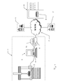
- Figure 3 shows, in a simplified form, a CMM 1 largely similar to the one of Figure 1 with an object to be measured 2 and a local computer terminal 3 that is connected to the CMM 1.
- the local computer terminal 3, as a control and calculation unit 3, comprises a processor and a memory 4.
- the control and calculation unit 3 is designed for determining three-space coordinates of measurement points of a feature of the object 2.
- the local computer terminal 3 is provided with a disk drive or additional memory 10, which is arranged externally in this embodiment, and connected to the internet 7 by a modem 9.
- the memory unit assigned to the measuring machine 1 is installed on the central computer 6 of a network and/or internet 7 server and made accessible to the local computer terminal 3 over a local network connection and/or the internet connection (modem) 9.
- the set of measurement software programmes for controlling the measuring machine 1 and assigned to the measuring machine 1 is installed on the central computer 6 of a network and/or internet 7 server and made accessible to the local computer terminal 3 over a local network connection and/or the internet connection (modem) 9.
- the set of measurement software programmes is additionally made available to further measuring machines 1', 1" via the internet 7.
- the memory unit and the set of measurement software programmes may be completely or partially be stored and executed on the local computer terminal 3 or the central computer 6.
- Figure 4 illustrates the method according to the invention for automated measurement of an object with a measuring machine, particularly a coordinate measuring machine, as described with reference to Figures 1 , 2 and 3 .
- CAD data 15 of the object to be measured are available and comprise typical dimensions /sizes and tolerances of one or more features 16. These data are typically stored in a data base as a part of a memory unit assigned to the measuring machine and stored at the site of local computer as a control and evaluation unit of the measuring machine or on a central computer of a network and/or an internet server, which is accessible from the local computer terminal over a local network connection and/or an interconnection, respectively.
- a further data base also located (at least partially) locally or (at least partially) externally or both, are stored probe systems and measuring machine parameters 300.
- a set 110 of measurement software programmes comprising an optimization algorithm, the set 110 comprising, for example, a programme (A) 111 dedicated for a feature 16A, a programme (B) 122 dedicated for a feature 16B, and a programme (C) 113 dedicated for a feature 16C.
- an operator selects, in a step 120, features of the object to be measured, for example features 16A, 16B, and 16C.
- This selection is transferred to the set 110 of measurement software programmes, and the optimization algorithm automatically selects, in a step 130, for each feature 16A, 16B, 16C chosen by the operator, measuring parameters 17A, 17B, 17C of the measuring machine 1, and/or a related measurement programme 111, 112,113 from the set 110 of measurement software programmes, to be executed in steps 111', 112', and/or 113', respectively.
- the automatic selection particularly depends on the stored typical dimensions and tolerances of the selected features 16A, 16B, and 16C. This is accompanied by a selection of a suitable probe system.
- the probe system is selected automatically depending on certain aspects, such as the needed accuracy, the throughput, the availability, etc.
- the system will automatically find out if there is a need for a datum and then select how to create it.
- Step 130 is followed typically, in a step 140, by an automatic recalibration of the machine accuracy levels required for the measurements of the selected features.
- the method step 130 also triggers an automatic generation of part programmes, in a step 170. This accomplishes the preparation phase of the measurement.
- a step 150 the operator loads the object to be measured into the measuring machine and, if necessary, a selected probe system. Then, in a step 160, the measurement is started. There will be one machine type (available in different sizes).
- the measured object data as real part measurement data, are compared with the CAD data 15, and deviations between the measured real data and the CAD data 15 are determined and presented.
- a first feature e. g. four cylinders
- a second feature e. g. twenty cooling outlets
- a third feature e. g. eight thread holes
- the system is able to automatically switch between the different modes.
- a further embodiment comprises a set 200 of optional features / additional steps insertable into, or more precisely parallel to, the flow of steps as described above, before the step 130.
- the optimization algorithm automatically selects and effects presentation to the operator of one more of:
- the operator may then select:
- an estimated time for measuring with certain measurement accuracies and/or an estimated accuracy when measuring for a certain time may be presented to an operator. Furthermore, a price for buying or renting a certain software programme 111, 112, 113 or a software package may be monitored. If the software is stored locally, e. g. there may be an enabling key for each programme or module, and if the software is hosted on a remote server, the "enabler" for the operator may be a business card.
- the optimization algorithm automatically then selects, in a step 130, for each feature 16A, 16B, 16C chosen by the operator, measuring parameters 17A, 17B, 17C of the measuring machine 1, and/or a related measurement programme 111, 112, 113 from the set 110 of measurement software programmes, thereby taking into account the feedback of the operator.
- the further sequence of method steps is then the same as described for the first embodiment of the inventive method.
Priority Applications (5)
| Application Number | Priority Date | Filing Date | Title |
|---|---|---|---|
| EP12193541.5A EP2735843A1 (de) | 2012-11-21 | 2012-11-21 | Messmaschine und Verfahren zur automatischen Messung eines Objekts |
| US14/646,365 US9683828B2 (en) | 2012-11-21 | 2013-11-20 | Measuring machine and method for automated measurement of an object |
| CN201380060962.XA CN104797907B (zh) | 2012-11-21 | 2013-11-20 | 用于物体自动测量的测量器和测量方法 |
| PCT/EP2013/074267 WO2014079871A2 (en) | 2012-11-21 | 2013-11-20 | Measuring machine and method for automated measurement of an object |
| EP13792925.3A EP2923172B1 (de) | 2012-11-21 | 2013-11-20 | Messgerät und verfahren zur automatischen objektvermessung |
Applications Claiming Priority (1)
| Application Number | Priority Date | Filing Date | Title |
|---|---|---|---|
| EP12193541.5A EP2735843A1 (de) | 2012-11-21 | 2012-11-21 | Messmaschine und Verfahren zur automatischen Messung eines Objekts |
Publications (1)
| Publication Number | Publication Date |
|---|---|
| EP2735843A1 true EP2735843A1 (de) | 2014-05-28 |
Family
ID=47358545
Family Applications (2)
| Application Number | Title | Priority Date | Filing Date |
|---|---|---|---|
| EP12193541.5A Withdrawn EP2735843A1 (de) | 2012-11-21 | 2012-11-21 | Messmaschine und Verfahren zur automatischen Messung eines Objekts |
| EP13792925.3A Active EP2923172B1 (de) | 2012-11-21 | 2013-11-20 | Messgerät und verfahren zur automatischen objektvermessung |
Family Applications After (1)
| Application Number | Title | Priority Date | Filing Date |
|---|---|---|---|
| EP13792925.3A Active EP2923172B1 (de) | 2012-11-21 | 2013-11-20 | Messgerät und verfahren zur automatischen objektvermessung |
Country Status (4)
| Country | Link |
|---|---|
| US (1) | US9683828B2 (de) |
| EP (2) | EP2735843A1 (de) |
| CN (1) | CN104797907B (de) |
| WO (1) | WO2014079871A2 (de) |
Cited By (2)
| Publication number | Priority date | Publication date | Assignee | Title |
|---|---|---|---|---|
| WO2016030268A1 (de) * | 2014-08-28 | 2016-03-03 | Carl Zeiss Industrielle Messtechnik Gmbh | Verfahren zur einzelpunktantastung eines werkstücks und koordinatenmessgerät |
| CN107548449A (zh) * | 2015-04-21 | 2018-01-05 | 卡尔蔡司工业测量技术有限公司 | 用于确定被测对象的实际尺寸特征的方法和装置 |
Families Citing this family (27)
| Publication number | Priority date | Publication date | Assignee | Title |
|---|---|---|---|---|
| WO2014029448A1 (en) * | 2012-08-24 | 2014-02-27 | Abb Technology Ltd | Calibration tool for a delta robot |
| CN104251676A (zh) * | 2013-06-28 | 2014-12-31 | 鸿富锦精密工业(深圳)有限公司 | 三次元测量装置 |
| EP2824420B1 (de) * | 2013-07-08 | 2019-03-06 | Hexagon Technology Center GmbH | Lagebestimmungseinrichtung mit einer inertialen Messeinheit |
| JP6219141B2 (ja) * | 2013-11-27 | 2017-10-25 | 株式会社ミツトヨ | 形状測定装置及び形状測定方法 |
| EP2881704B1 (de) * | 2013-12-04 | 2018-05-09 | Hexagon Technology Center GmbH | Systeme und Verfahren zur automatischen Messung eines Objekts und entsprechendes Computerprogrammprodukt |
| EP2887011B1 (de) * | 2013-12-20 | 2017-02-08 | Hexagon Technology Center GmbH | Koordinatenmessmaschine mit hochpräziser 3D-Druckfunktionalität |
| JP2015141139A (ja) * | 2014-01-29 | 2015-08-03 | 株式会社ミツトヨ | 手動測定装置 |
| EP2998696B1 (de) * | 2014-09-18 | 2021-01-06 | Hexagon Technology Center GmbH | Verfahren zur Kompensation des richtungsabhängigen Verhaltens einer Tastsonde einer Koordinatenmessmaschine |
| US9557157B2 (en) | 2014-12-01 | 2017-01-31 | Steven Eugene Ihlenfeldt | Inertial dimensional metrology |
| EP3054265B1 (de) * | 2015-02-04 | 2022-04-20 | Hexagon Technology Center GmbH | Koordinatenmessmaschine |
| US9646425B2 (en) * | 2015-04-09 | 2017-05-09 | Mitutoyo Corporation | Inspection program editing environment with editing environment automatically globally responsive to editing operations in any of its portions |
| US9952586B2 (en) | 2015-04-09 | 2018-04-24 | Mitutoyo Corporation | Inspection program editing environment with simulation status and control continually responsive to selection operations |
| US9933256B2 (en) | 2015-04-09 | 2018-04-03 | Mitutoyo Corporation | Inspection program editing environment including real-time feedback related to throughput |
| US11520472B2 (en) * | 2015-09-24 | 2022-12-06 | Mitutoyo Corporation | Inspection program editing environment including integrated alignment program planning and editing features |
| JP6295299B2 (ja) * | 2016-08-26 | 2018-03-14 | 株式会社ミツトヨ | 座標補正方法及び三次元測定装置 |
| JP6752092B2 (ja) * | 2016-09-13 | 2020-09-09 | 株式会社ミツトヨ | 真円度測定機 |
| US10832358B2 (en) * | 2017-01-19 | 2020-11-10 | International Business Machines Corporation | Disposition manager for resource recovery |
| US11092421B2 (en) * | 2017-10-09 | 2021-08-17 | Gagemaker, L.P. | Automated dynamic dimensional measurement systems and methods |
| CN109916350B (zh) * | 2017-12-12 | 2021-01-01 | 深圳模德宝科技有限公司 | 一种生成三坐标测量程序的方法、装置及终端设备 |
| GB2580684A (en) * | 2019-01-24 | 2020-07-29 | Rolls Royce Plc | Coordinate measurement validation |
| EP3839415A1 (de) * | 2019-12-17 | 2021-06-23 | Carl Zeiss Industrielle Messtechnik GmbH | Verfahren zur planung von messpfaden eines messgerätes |
| US11162770B2 (en) * | 2020-02-27 | 2021-11-02 | Proto Labs, Inc. | Methods and systems for an in-line automated inspection of a mechanical part |
| CN113536656A (zh) * | 2020-04-21 | 2021-10-22 | 卡尔蔡司工业测量技术有限公司 | 用于确定测量测量物体的测量策略的方法和设备及程序 |
| EP3901563B1 (de) * | 2020-04-21 | 2022-12-14 | Carl Zeiss Industrielle Messtechnik GmbH | Verfahren und vorrichtung zur bestimmung einer messstrategie zur vermessung eines messobjekts und programm |
| CN111678477A (zh) * | 2020-06-20 | 2020-09-18 | 贵阳航发精密铸造有限公司 | 一种涡轮工作叶片最终检验自动检测测量方法 |
| CN111784803A (zh) * | 2020-07-01 | 2020-10-16 | 长江三峡勘测研究院有限公司(武汉) | 钻孔岩芯相互关系数据的自动采集系统及方法 |
| CN112050767A (zh) * | 2020-08-28 | 2020-12-08 | 南京昆程仕科技有限公司 | 一种面向教育版的微型坐标测量机 |
Citations (5)
| Publication number | Priority date | Publication date | Assignee | Title |
|---|---|---|---|---|
| US5465221A (en) * | 1993-12-30 | 1995-11-07 | The United States Of America As Represented By The Secretary Of The Air Force | Automated process planning for quality control inspection |
| JPH09178469A (ja) | 1995-12-26 | 1997-07-11 | Tokyo Seimitsu Co Ltd | 真円度測定機のパートプログラム自動選択装置 |
| WO2002023292A2 (de) * | 2000-09-15 | 2002-03-21 | Werth Messtechnik Gmbh | Verfahren zum generieren eines messprogrammes für ein koordinatenmessgerät |
| US20050171733A1 (en) * | 2002-05-14 | 2005-08-04 | Hough Gerald W. | Method of generating an inspection program and method of generating a visual display |
| DE10130737B4 (de) | 2001-06-19 | 2005-09-08 | Kelch Gmbh + Co. Kg Werkzeugmaschinenfabrik | Einstellsystem für Werkzeuge |
Family Cites Families (19)
| Publication number | Priority date | Publication date | Assignee | Title |
|---|---|---|---|---|
| JP3028786B2 (ja) | 1997-07-03 | 2000-04-04 | 日本電気株式会社 | デジタル伝送路の収容位置情報セーブ方式 |
| JP2003181842A (ja) | 2001-12-14 | 2003-07-02 | Futaba Corp | 金型用部品設計支援方法、及び、そのシステム |
| JP5274782B2 (ja) * | 2007-03-27 | 2013-08-28 | 株式会社ミツトヨ | 表面性状測定装置、表面性状測定方法及び表面性状測定プログラム |
| CN101581579B (zh) | 2008-05-16 | 2011-12-21 | 鸿富锦精密工业(深圳)有限公司 | 二维曲线色阶比对方法 |
| CN101587504A (zh) | 2008-05-21 | 2009-11-25 | 鸿富锦精密工业(深圳)有限公司 | 自定义曲面检测报告系统及方法 |
| DE102008034117A1 (de) | 2008-07-21 | 2010-02-04 | Carl Zeiss Industrielle Messtechnik Gmbh | Verfahren und Vorrichtung zum Herstellen eines Urformwerkzeugs |
| WO2010049693A2 (en) | 2008-10-29 | 2010-05-06 | Renishaw Plc | Measurement method |
| CN101758377A (zh) | 2008-11-14 | 2010-06-30 | 王万龙 | 加工检测一体化复合型数控机床 |
| EP2270425A1 (de) * | 2009-07-03 | 2011-01-05 | Leica Geosystems AG | Koordinatenmessmaschine und Verfahren zum Kompensieren von Fehlern in einer Koordinatenmessmaschine |
| CN102713499B (zh) | 2010-01-20 | 2014-07-09 | 法罗技术股份有限公司 | 用于坐标测量设备的配重 |
| DE102010014423A1 (de) | 2010-03-31 | 2011-10-06 | Carl Zeiss Industrielle Messtechnik Gmbh | Starten einer Messprozedur zum Messen von Koordinaten eines Werkstücks |
| EP2505956A1 (de) * | 2011-03-29 | 2012-10-03 | Hexagon Technology Center GmbH | Koordinatenmessmaschine |
| JP6154605B2 (ja) * | 2012-09-04 | 2017-06-28 | 株式会社ミツトヨ | 形状測定装置及び形状測定誤差の補正方法 |
| JP6114010B2 (ja) * | 2012-11-14 | 2017-04-12 | 株式会社ミツトヨ | 形状測定装置及び形状測定誤差の補正方法 |
| EP2984442B1 (de) * | 2013-04-02 | 2017-03-08 | Carl Zeiss Industrielle Messtechnik GmbH | Verfahren zum bestimmen einer formkontur an einem messobjekt |
| JP2015141139A (ja) * | 2014-01-29 | 2015-08-03 | 株式会社ミツトヨ | 手動測定装置 |
| EP2930462B1 (de) * | 2014-04-08 | 2017-09-13 | Hexagon Technology Center GmbH | Verfahren zur Erzeugung von Informationen über eine Sensorkette einer Koordinatenmessmaschine (CMM) |
| JP6484108B2 (ja) * | 2015-05-22 | 2019-03-13 | 株式会社ミツトヨ | 形状測定装置の制御方法 |
| EP3104118B1 (de) * | 2015-06-12 | 2019-02-27 | Hexagon Technology Center GmbH | Verfahren zur steuerung eines antriebsmechanismus einer automatisierten maschine mit einer kamera |
-
2012
- 2012-11-21 EP EP12193541.5A patent/EP2735843A1/de not_active Withdrawn
-
2013
- 2013-11-20 WO PCT/EP2013/074267 patent/WO2014079871A2/en active Application Filing
- 2013-11-20 US US14/646,365 patent/US9683828B2/en active Active
- 2013-11-20 EP EP13792925.3A patent/EP2923172B1/de active Active
- 2013-11-20 CN CN201380060962.XA patent/CN104797907B/zh active Active
Patent Citations (5)
| Publication number | Priority date | Publication date | Assignee | Title |
|---|---|---|---|---|
| US5465221A (en) * | 1993-12-30 | 1995-11-07 | The United States Of America As Represented By The Secretary Of The Air Force | Automated process planning for quality control inspection |
| JPH09178469A (ja) | 1995-12-26 | 1997-07-11 | Tokyo Seimitsu Co Ltd | 真円度測定機のパートプログラム自動選択装置 |
| WO2002023292A2 (de) * | 2000-09-15 | 2002-03-21 | Werth Messtechnik Gmbh | Verfahren zum generieren eines messprogrammes für ein koordinatenmessgerät |
| DE10130737B4 (de) | 2001-06-19 | 2005-09-08 | Kelch Gmbh + Co. Kg Werkzeugmaschinenfabrik | Einstellsystem für Werkzeuge |
| US20050171733A1 (en) * | 2002-05-14 | 2005-08-04 | Hough Gerald W. | Method of generating an inspection program and method of generating a visual display |
Cited By (6)
| Publication number | Priority date | Publication date | Assignee | Title |
|---|---|---|---|---|
| WO2016030268A1 (de) * | 2014-08-28 | 2016-03-03 | Carl Zeiss Industrielle Messtechnik Gmbh | Verfahren zur einzelpunktantastung eines werkstücks und koordinatenmessgerät |
| CN107076552A (zh) * | 2014-08-28 | 2017-08-18 | 卡尔蔡司工业测量技术有限公司 | 用于工件的单点扫描的方法和坐标测量机 |
| US10508895B2 (en) | 2014-08-28 | 2019-12-17 | Carl Zeiss Industrielle Messtechnik Gmbh | Method for single-point scanning of a workpiece and coordinate measuring machine |
| CN107548449A (zh) * | 2015-04-21 | 2018-01-05 | 卡尔蔡司工业测量技术有限公司 | 用于确定被测对象的实际尺寸特征的方法和装置 |
| CN107548449B (zh) * | 2015-04-21 | 2019-11-12 | 卡尔蔡司工业测量技术有限公司 | 用于确定被测对象的实际尺寸特征的方法和装置 |
| US10767988B2 (en) | 2015-04-21 | 2020-09-08 | Carl Zeiss Industrielle Messtechnik Gmbh | Method and device for determining actual dimensional properties of a measured object |
Also Published As
| Publication number | Publication date |
|---|---|
| US9683828B2 (en) | 2017-06-20 |
| EP2923172A2 (de) | 2015-09-30 |
| CN104797907A (zh) | 2015-07-22 |
| WO2014079871A2 (en) | 2014-05-30 |
| EP2923172B1 (de) | 2019-05-22 |
| CN104797907B (zh) | 2018-03-13 |
| US20150300798A1 (en) | 2015-10-22 |
| WO2014079871A3 (en) | 2014-07-17 |
Similar Documents
| Publication | Publication Date | Title |
|---|---|---|
| EP2923172B1 (de) | Messgerät und verfahren zur automatischen objektvermessung | |
| EP2930462B1 (de) | Verfahren zur Erzeugung von Informationen über eine Sensorkette einer Koordinatenmessmaschine (CMM) | |
| CN102472617B (zh) | 工件测量装置、防止碰撞装置和机床 | |
| JP4675047B2 (ja) | 三次元測定機の測定座標補正方法及び三次元測定システム | |
| He et al. | A new error measurement method to identify all six error parameters of a rotational axis of a machine tool | |
| Hong et al. | Non-contact R-test with laser displacement sensors for error calibration of five-axis machine tools | |
| CN104204717B (zh) | 确定用于监测流体轴承和具有至少一个流体轴承的机器的校正值的方法 | |
| JP2007315897A (ja) | 測定装置、表面性状測定方法、及び表面性状測定プログラム | |
| US11221201B2 (en) | Profile measuring machine and profile measuring method | |
| US10508895B2 (en) | Method for single-point scanning of a workpiece and coordinate measuring machine | |
| JP6676730B2 (ja) | ねじ山のゲージレス測定のための方法およびシステム | |
| US6701267B2 (en) | Method for calibrating probe and computer-readable medium | |
| US20200149859A1 (en) | Measuring apparatus counterbalance | |
| JP6016321B2 (ja) | 座標測定器の動作制御 | |
| JP2006308476A (ja) | 表面粗さ/形状測定装置 | |
| JP2007292474A (ja) | 三次元形状測定装置 | |
| JP5272248B2 (ja) | 表面性状測定装置、表面性状測定方法、及びプログラム | |
| JP6800421B1 (ja) | 測定装置及び測定方法 | |
| JP2018004362A (ja) | パートプログラム選択装置、産業機械、及びパートプログラム選択方法 | |
| JP2007333442A (ja) | 形状測定方法 | |
| EP4212822A1 (de) | Abbildung von sensorfehlerdaten aus einer koordinatenpositionierungsmaschine | |
| JP5121292B2 (ja) | 形状測定方法及び装置 | |
| WO2023066936A1 (en) | Mapping of sensor error data from a coordinate positioning machine | |
| JPH1158182A (ja) | 工作機械精度計測システム | |
| KR20050055184A (ko) | 캐드캠을 이용한 공작기계 가공물 기상측정방법 |
Legal Events
| Date | Code | Title | Description |
|---|---|---|---|
| PUAI | Public reference made under article 153(3) epc to a published international application that has entered the european phase |
Free format text: ORIGINAL CODE: 0009012 |
|
| 17P | Request for examination filed |
Effective date: 20121121 |
|
| AK | Designated contracting states |
Kind code of ref document: A1 Designated state(s): AL AT BE BG CH CY CZ DE DK EE ES FI FR GB GR HR HU IE IS IT LI LT LU LV MC MK MT NL NO PL PT RO RS SE SI SK SM TR |
|
| AX | Request for extension of the european patent |
Extension state: BA ME |
|
| STAA | Information on the status of an ep patent application or granted ep patent |
Free format text: STATUS: THE APPLICATION IS DEEMED TO BE WITHDRAWN |
|
| 18D | Application deemed to be withdrawn |
Effective date: 20141129 |