EP2728093A1 - Sicherheitssystem mit einem Unfallerkennungssensor - Google Patents
Sicherheitssystem mit einem Unfallerkennungssensor Download PDFInfo
- Publication number
- EP2728093A1 EP2728093A1 EP13184441.7A EP13184441A EP2728093A1 EP 2728093 A1 EP2728093 A1 EP 2728093A1 EP 13184441 A EP13184441 A EP 13184441A EP 2728093 A1 EP2728093 A1 EP 2728093A1
- Authority
- EP
- European Patent Office
- Prior art keywords
- lock
- detection sensor
- safety system
- accident detection
- accident
- Prior art date
- Legal status (The legal status is an assumption and is not a legal conclusion. Google has not performed a legal analysis and makes no representation as to the accuracy of the status listed.)
- Granted
Links
Images


Classifications
-
- E—FIXED CONSTRUCTIONS
- E05—LOCKS; KEYS; WINDOW OR DOOR FITTINGS; SAFES
- E05B—LOCKS; ACCESSORIES THEREFOR; HANDCUFFS
- E05B77/00—Vehicle locks characterised by special functions or purposes
- E05B77/02—Vehicle locks characterised by special functions or purposes for accident situations
- E05B77/04—Preventing unwanted lock actuation, e.g. unlatching, at the moment of collision
- E05B77/06—Preventing unwanted lock actuation, e.g. unlatching, at the moment of collision by means of inertial forces
-
- E—FIXED CONSTRUCTIONS
- E05—LOCKS; KEYS; WINDOW OR DOOR FITTINGS; SAFES
- E05B—LOCKS; ACCESSORIES THEREFOR; HANDCUFFS
- E05B77/00—Vehicle locks characterised by special functions or purposes
- E05B77/02—Vehicle locks characterised by special functions or purposes for accident situations
- E05B77/12—Automatic locking or unlocking at the moment of collision
-
- B—PERFORMING OPERATIONS; TRANSPORTING
- B60—VEHICLES IN GENERAL
- B60R—VEHICLES, VEHICLE FITTINGS, OR VEHICLE PARTS, NOT OTHERWISE PROVIDED FOR
- B60R21/00—Arrangements or fittings on vehicles for protecting or preventing injuries to occupants or pedestrians in case of accidents or other traffic risks
- B60R21/01—Electrical circuits for triggering passive safety arrangements, e.g. airbags, safety belt tighteners, in case of vehicle accidents or impending vehicle accidents
- B60R21/013—Electrical circuits for triggering passive safety arrangements, e.g. airbags, safety belt tighteners, in case of vehicle accidents or impending vehicle accidents including means for detecting collisions, impending collisions or roll-over
- B60R21/0132—Electrical circuits for triggering passive safety arrangements, e.g. airbags, safety belt tighteners, in case of vehicle accidents or impending vehicle accidents including means for detecting collisions, impending collisions or roll-over responsive to vehicle motion parameters, e.g. to vehicle longitudinal or transversal deceleration or speed value
-
- E—FIXED CONSTRUCTIONS
- E05—LOCKS; KEYS; WINDOW OR DOOR FITTINGS; SAFES
- E05B—LOCKS; ACCESSORIES THEREFOR; HANDCUFFS
- E05B81/00—Power-actuated vehicle locks
- E05B81/54—Electrical circuits
-
- E—FIXED CONSTRUCTIONS
- E05—LOCKS; KEYS; WINDOW OR DOOR FITTINGS; SAFES
- E05B—LOCKS; ACCESSORIES THEREFOR; HANDCUFFS
- E05B81/00—Power-actuated vehicle locks
- E05B81/54—Electrical circuits
- E05B81/64—Monitoring or sensing, e.g. by using switches or sensors
- E05B81/76—Detection of handle operation; Detection of a user approaching a handle; Electrical switching actions performed by door handles
- E05B81/77—Detection of handle operation; Detection of a user approaching a handle; Electrical switching actions performed by door handles comprising sensors detecting the presence of the hand of a user
-
- E—FIXED CONSTRUCTIONS
- E05—LOCKS; KEYS; WINDOW OR DOOR FITTINGS; SAFES
- E05B—LOCKS; ACCESSORIES THEREFOR; HANDCUFFS
- E05B81/00—Power-actuated vehicle locks
- E05B81/54—Electrical circuits
- E05B81/90—Manual override in case of power failure
Definitions
- the invention relates to a safety system of a motor vehicle, comprising a lock, which can be brought into at least two states in order to lock and / or unlock a movable part of the motor vehicle, to a sensor element which can be activated by a user to the state of the lock and an electronics unit that is in signal communication with the lock and sensor element.
- a sensor element on the motor vehicle which can be activated by the user in order to influence the state of a lock on the motor vehicle.
- the user can via an activation of the sensor element, which z. B. may be a switch, bring the lock between a locking position and an open position.
- the securing position for example, the tailgate or the door of Motor vehicle held, for example via a trapping element, so that an opening of the door or the tailgate is prevented.
- the door or tailgate may be locked.
- the door or the tailgate is unlocked, so that an opening operation of the door or the tailgate is executable.
- the sensor element is in signal connection with the lock, so that depending on the activation state of the sensor element, the lock can be electronically controlled accordingly.
- An electronic unit also favors reliable communication between the sensor element and the lock. Disadvantageously, it has been shown that in an accident situation, the circuit consisting of sensor element, electronics unit and lock can be affected or destroyed, while a false signal can be triggered, in which the lock in the state of the open position can be brought, which during the accident situation, however urgently to be avoided.
- the object of the present invention is to avoid the above-mentioned disadvantages, in particular to provide a safety system in which there is no risk in the event of an accident occurring that the movable part of the motor vehicle, in particular the tailgate or the door opens.
- an accident detection sensor is provided, whose operation is designed such that in an accident situation the accident detection sensor prevents a change of state of the castle.
- An essential core of the invention is that the accident detection sensor according to the invention of the circuit, at least composed of sensor element, electronic unit and lock, the information is available and informs that an accident situation exists. This information can now be processed by the circuit so that it is effectively prevented that the lock undergoes a state change, in particular from a securing position, which it occupies during operation of the motor vehicle, changes to an open position at there is an unlocking of the movable part and thus an opening operation of the movable part can be triggered.
- the safety system according to the invention can be designed such that the accident detection sensor interrupts the signal connection to the lock in the accident situation, in particular interrupts the signal connection between the sensor element and the lock.
- the interruption of the signal connection ensures that no false signal can be transmitted to the lock, with which a possible state change, which is not wanted, would be connected.
- the interruption of the signal connection can, for. B. between the sensor element and the electronics unit or between the electronic unit and the lock.
- a switch may be provided which is in signal communication with the accident detection sensor, wherein in the accident situation the switch interrupts the signal connection between the sensor element and the lock and / or switches in the accident situation such that a change of state of the lock is prevented.
- the switch may be connected between the sensor element and the electronics unit or between the electronics unit and the lock.
- the switch can be executed, for example, as a change-over contact or as an opener or as a make contact.
- the switch is integrated in the accident detection sensor. This means that the accident detection sensor with the switch has the function to detect the possible accident situation and at the same time to ensure in case of an accident situation that the state change of the lock is prevented. As a result, the number of modules in the overall security system can be significantly reduced.
- the invention may include that the accident detection sensor is in signal communication with the electronic unit such that in the accident situation the accident detection sensor transmits a defined signal to the electronic unit which controls the lock so that the lock remains unchanged in its state, in particular that the movable Part locked remains.
- the electronic unit can recognize on the basis of the defined signal that an accident situation exists, so that no activation of the lock takes place or the lock remains unchanged in its state. It is also conceivable that the electronic unit, although the electronic device, the defined signal, which is characteristic of an accident situation, is forwarded to the lock, but this is not controlled for a state change.
- the lock may be an electromechanical lock, which is electronically controlled by the electronic unit and / or by the vehicle-mounted control. This means that a signal, triggered by the activation of the sensor element by the user, the electromechanical lock is brought into its respective state or changes.
- the sensor element may be a touch sensor or a proximity sensor, in particular a piezo sensor and / or a capacitive sensor.
- the security system can be designed in such a way that an authentication query is started for an actual state influencing of the lock. This means that the authentication query checks to what extent the user who activates the sensor element is actually authorized to change the state of the lock. It is conceivable that a data communication between an identification transmitter, which the user carries with him, and a motor vehicle side transceiver unit takes place. If there is a positive authentication, a change of state via the security system according to the invention is possible.
- the accident detection sensor can be integrated in the electronics unit.
- the electronic unit, including the accident detection sensor or without the accident detection sensor is integrated in the lock or lock.
- the switch which is in signal communication with the accident detection sensor, may also be integrated in the lock or lock.
- the motor vehicle may have a handle accessible to the user, in particular a door handle, in which the sensor element is integrated, wherein in particular the electronic unit and / or the switch and / or the accident detection sensor is integrated in the handle.
- the sensor element can be designed as a button, switch, etc., wherein advantageously the arrangement of said components within the door handle or within the handle ensures reliable functionality. This means that an accident situation can be reliably detected by concentrating the components just mentioned within the handle and at the same time the circuit according to the invention can be switched within the handle in order to prevent the lock from carrying out an undesired change of state.
- the lock is arranged on the movable part, wherein the movable part is a tailgate or a door. Also included is that the movable part may also be a fuel cap of the motor vehicle, which can be unlocked or locked from the lock.
- the invention comprises that the accident detection sensor is an acceleration sensor and / or a position sensor.
- the accident detection sensor may be a contact sensor or a rollover sensor, which detects and / or senses an accident event. It is also conceivable that the accident detection sensor of the airbag system is used to detect an accident situation.
- a deformation sensor can be used, wherein in an accident, an area of the motor vehicle is deformed, senses the deformation sensor.
- the invention can provide that the accident detection sensor is connected to the lock such that in the accident situation the accident detection sensor only temporarily prevents a change of state of the lock, in particular for less than 10 milliseconds a change of state of the lock is prevented.
- the safety system is again switched to a normal mode, so that the user can activate the sensor element in the usual way in order to achieve a change of state of the lock.
- FIG. 1 a safety system of a motor vehicle 2 is shown, which has a lock 10, which can be brought into at least two states.
- the lock 10 In the first state, the lock 10 is in an open position, in which a movable part 30 of the motor vehicle 2, in particular the door 30 can be opened by the user.
- the lock 10 In a second state of the lock 10, the lock 10 assumes a securing position in which the door 30 is locked and thus can not be opened by the user.
- the motor vehicle 2 further comprises a handle 32 which is formed in the present embodiment as a door handle.
- the handle 32 is spaced from the lock 10.
- the lock 10 can be actuated electronically via a sensor element 31, which is integrated in the handle 32 in the illustrated embodiment.
- the security system has an electronic unit 20 which is in signal connection with the lock 10 and the sensor element 31. Via a manual actuation or activation of the sensor element 31, the user can influence or change the state of the lock 10. So that the state change is also carried out within the security system, an authentication query is advantageously carried out to what extent the user is entitled to influence the lock 10 with respect to his state.
- the safety system has an accident detection sensor 40, whose operation is designed such that in an accident situation the accident detection sensor 40 prevents a change of state of the lock 10.
- the accident detection sensor 40 is integrated in the circuit of the safety system that in the accident situation, the signal connection to the lock 10 is interrupted by the accident detection sensor 40.
- the signal connection between the sensor element 31 and the electronics unit 20 or the signal connection between the electronics unit 20 and the lock 10 is interrupted.
- the electronics unit 20 has the task to communicate with the electromechanical lock 10, in particular to be in data communication in order to control the lock 10 in accordance with the activation of the sensor element 31.
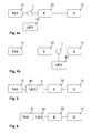
- FIG. 3 an embodiment of the safety system according to the invention is shown, in which the accident detection sensor 40 transmits a defined signal in an accident situation of the electronic unit 20.
- the electronic unit 20 evaluates the signal of the accident detection sensor 40. If the signal evaluated by the accident detection sensor 40 corresponds to a defined value or threshold value, which means for the electronic unit 20 that an accident actually exists, the electronic unit 20 prevents the lock 10 from changing its state, in particular that the lock 10 is brought into such a state is that a release or opening of the door 30 can be effected.
- FIG. 4a the embodiment of the safety system is shown, in which a switch 1 is integrated within the circuit which is in signal communication with the accident detection sensor 40.
- the switch 1 interrupts the signal connection between the sensor element 31 and the electronics unit 20.
- the switch 1 is located between the sensor element 31 and the electronic unit 20
- FIG. 4b a further alternative is shown, in which the switch 1 can be arranged between the electronic unit 20 and the lock 10.
- the switch 1 according to Figure 4a, 4b can also be designed such that it switches in an accident situation so that a change of state of the lock 10 is prevented.
- the switch 1 may be a changer, an opener or a closer.
- FIG. 11 and FIG. 12 It is shown that in the handle 32, in particular in the door handle, the sensor element 31 is integrated.
- the lock 10 is located on the door 30, spaced from the handle 32. Between the handle 32 and the lock 10, the electronics unit 20 is arranged. It is now conceivable that the accident detection sensor according to, for example FIG. 11 can be arranged on the lock 10. It is also conceivable that the accident detection sensor according to FIG. 12 can be integrated in the handle 32.
- FIG. 5 For example, it is conceivable that the accident detection sensor 40 with the switch 1 form a common component. Also, an alternative of the invention may be to integrate the accident detection sensor 40 in the sensor element 31, which in FIG. 6 is shown.
- FIG. 7 schematically shows that the accident detection sensor 40 may be integrated in the electronic unit 20.
- FIGS. 8 to 10 show that the lock 10 with the electronic unit 20 and / or with the accident detection sensor 40 and / or with the switch 1 can form a component. All alternatives according to FIG. 5 to FIG. 10 can in the embodiments according to FIG. 1 to FIG. 4 such as FIG. 11 to FIG. 12 be combined.
Landscapes
- Lock And Its Accessories (AREA)
Abstract
Description
- Die Erfindung betrifft ein Sicherheitssystem eines Kraftfahrzeuges, mit einem Schloss, das in mindestens zwei Zustände bringbar ist, um ein bewegliches Teil des Kraftfahrzeuges zu verriegeln und/oder zu entriegeln, einem Sensorelement, das durch einen Benutzer aktivierbar ist, um den Zustand des Schlosses zu beeinflussen, und einer Elektronikeinheit, die in einer Signalverbindung mit dem Schloss und dem Sensorelement ist.
- Aus dem Stand der Technik ist es bekannt, ein Sensorelement am Kraftfahrzeug einzusetzen, das durch den Benutzer aktivierbar ist, um den Zustand eines Schlosses am Kraftfahrzeug zu beeinflussen. Der Benutzer kann über eine Aktivierung des Sensorelementes, welches z. B. ein Schalter sein kann, das Schloss zwischen einer Sicherungsstellung und einer Offenstellung bringen. In der Sicherungsstellung wird beispielsweise die Heckklappe oder die Tür des Kraftfahrzeuges gehalten, beispielsweise über ein Fallenelement, sodass eine Öffnung der Tür oder der Heckklappe verhindert ist. Beispielsweise kann in der Sicherungsstellung die Tür oder die Heckklappe verriegelt sein. Bei einem Wechsel des Zustandes in die Offenstellung ist die Tür oder die Heckklappe entriegelt, sodass ein Öffnungsvorgang der Tür oder der Heckklappe ausführbar ist. Das Sensorelement ist in Signalverbindung mit dem Schloss, sodass je nach Aktivierungszustand des Sensorelementes das Schloss elektronisch entsprechend angesteuert werden kann. Eine Elektronikeinheit begünstigt zudem eine zuverlässige Kommunikation zwischen dem Sensorelement und dem Schloss. Nachteiligerweise hat sich gezeigt, dass bei einer Unfallsituation die Schaltung bestehend aus Sensorelement, Elektronikeinheit und Schloss beeinflusst bzw. zerstört werden kann, wobei gleichzeitig ein Fehlsignal ausgelöst werden kann, bei dem das Schloss in den Zustand der Offenstellung bringbar ist, welches während der Unfallsituation jedoch dringend zu vermeiden ist.
- Die Aufgabe der vorliegenden Erfindung ist es, die oben genannten Nachteile zu vermeiden, insbesondere ein Sicherheitssystem zu schaffen, bei dem bei einer etwaigen eintretenden Unfallsituation nicht die Gefahr besteht, dass das bewegliche Teil des Kraftfahrzeuges, insbesondere die Heckklappe oder die Tür sich öffnet.
- Die Aufgabe der vorliegenden Erfindung wird durch sämtliche Merkmale des Patentanspruches 1 gelöst. In den abhängigen Ansprüchen sind vorteilhafte Ausführungsformen ausgeführt.
- Erfindungsgemäß ist ein Unfallerkennungssensor vorgesehen, dessen Funktionsweise derart ausgebildet ist, dass in einer Unfallsituation der Unfallerkennungssensor einen Zustandswechsel des Schlosses unterbindet. Ein wesentlicher Kern der Erfindung ist, dass der erfindungsgemäße Unfallerkennungssensor der Schaltung, zumindest sich zusammensetzend aus Sensorelement, Elektronikeinheit und Schloss, die Information zur Verfügung stellt und mitteilt, dass eine Unfallsituation vorliegt. Diese Information kann von der Schaltung nun derart verarbeitet werden, dass wirkungsvoll verhindert wird, dass das Schloss einen Zustandswechsel erfährt, insbesondere aus einer Sicherungsstellung, die es während des Betriebes des Kraftfahrzeuges einnimmt, in eine Offenstellung wechselt, bei der eine Entriegelung des beweglichen Teils vorliegt und somit ein Öffnungsvorgang des beweglichen Teils auslösbar ist.
- Das erfindungsgemäße Sicherheitssystem kann derart ausgeführt sein, dass der Unfallerkennungssensor in der Unfallsituation die Signalverbindung zum Schloss unterbricht, insbesondere die Signalverbindung zwischen dem Sensorelement und dem Schloss unterbricht. Die Unterbrechung der Signalverbindung bewirkt, dass kein Fehlsignal dem Schloss übermittelt werden kann, mit dem ein möglicher Zustandswechsel, der nicht gewollt ist, verbunden wäre. Die Unterbrechung der Signalverbindung kann z. B. zwischen dem Sensorelement und der Elektronikeinheit oder zwischen der Elektronikeinheit und dem Schloss vorliegen.
- In einer möglichen Ausführungsform kann ein Schalter vorgesehen sein, der mit dem Unfallerkennungssenor in Signalverbindung steht, wobei in der Unfallsituation der Schalter die Signalverbindung zwischen dem Sensorelement und dem Schloss unterbricht und/oder derart in der Unfallsituation schaltet, dass ein Zustandswechsel des Schlosses unterbunden ist. Der Schalter kann zwischen dem Sensorelement und der Elektronikeinheit oder zwischen der Elektronikeinheit und dem Schloss geschaltet sein. Der Schalter ist beispielsweise als Wechsler oder als Öffner oder als ein Schließer ausführbar.
- In einer weiteren die Erfindung verbessernden Maßnahme kann vorgesehen sein, dass der Schalter im Unfallerkennungssensor integriert ist. Das bedeutet, dass der Unfallerkennungssensor mit dem Schalter die Funktion aufweist, die mögliche Unfallsituation zu erkennen und gleichzeitig im Falle einer Unfallsituation dafür zu sorgen, dass der Zustandswechsel des Schlosses verhindert wird. Hierdurch lässt sich die Anzahl der Baugruppen im Gesamtsicherheitssystem wesentlich reduzieren.
- Zudem kann die Erfindung mit umfassen, dass der Unfallerkennungssensor derart in Signalverbindung mit der Elektronikeinheit steht, dass in der Unfallsituation der Unfallerkennungssensor ein definiertes Signal der Elektronikeinheit übergibt, die das Schloss so ansteuert, dass das Schloss unverändert in seinem Zustand verbleibt, insbesondere dass das bewegliche Teil verriegelt verbleibt. Bei dieser Ausführungsform der Erfindung erfolgt keine unmittelbare Unterbrechung der Signalverbindung zum Schloss, sondern eine intelligente Informationsübergabe von einem oder mehreren Signalen, welches von der Elektronikeinheit ausgewertet wird. Die Elektronikeinheit kann anhand des definierten Signals erkennen, dass eine Unfallsituation vorliegt, sodass keine Ansteuerung des Schlosses erfolgt bzw. das Schloss unverändert in seinem Zustand verbleibt. Ebenfalls ist es denkbar, dass die Elektronikeinheit das definierte Signal, welches charakteristisch für eine Unfallsituation ist, zwar an das Schloss elektronisch weitergeleitet wird, dieses jedoch für einen Zustandswechsel nicht angesteuert wird.
- Um eine kompakte Gesamtanordnung zu schaffen kann die Erfindung derart weitergebildet sein, dass der Unfallerkennungssensor im Sensorelement integriert ist. Das Schloss kann ein elektromechanisches Schloss sein, welches elektronisch durch die Elektronikeinheit und/oder durch die fahrzeugseitige Steuerung ansteuerbar ist. Das bedeutet, dass über ein Signal, ausgelöst durch die Aktivierung des Sensorelementes durch den Benutzer, das elektromechanische Schloss in seinen jeweiligen Zustand gebracht wird oder wechselt. Das Sensorelement kann ein Berührungssensor oder ein Annäherungssensor sein, insbesondere einen Piezosensor und/oder einen kapazitiven Sensor aufweisen.
- Das Sicherheitssystem kann erfindungsgemäß derart ausgeführt sein, dass für eine tatsächliche Zustandsbeeinflussung des Schlosses eine Authentifizierungsabfrage gestartet wird. Das bedeutet, dass die Authentifizierungsabfrage überprüft, inwieweit der Benutzer, der das Sensorelement aktiviert, tatsächlich berechtigt ist, einen Zustandswechsel des Schlosses durchzuführen. Denkbar ist, dass eine Datenkommunikation zwischen einem Identifikationsgeber, den der Benutzer bei sich trägt, und einer kraftfahrzeugseitigen Sende-Empfangseinheit erfolgt. Liegt eine positive Authentifizierung vor, ist ein Zustandswechsel über das erfindungsgemäße Sicherheitssystem möglich.
- In einer weiteren Ausführungsform der Erfindung kann der Unfallerkennungssensor in der Elektronikeinheit integriert sein. Des Weiteren ist es denkbar, dass die Elektronikeinheit, einschließlich des Unfallerkennungssensors oder ohne den Unfallerkennungssensor im Schloss bzw. am Schloss integriert ist. Somit können kompakte Baueinheiten innerhalb des Sicherheitssystems geschaffen werden, wodurch auch der Montageaufwand am Kraftfahrzeug wesentlich reduzierbar ist.
- Beispielsweise ist es in einer weiteren Ausführungsform des erfindungsgemäßen Sicherheitssystems möglich, den Unfallerkennungssensor im oder am Schloss zu integrieren. Auch hier ergeben sich Vorteile bzgl. der Anzahl an Einzelkomponenten innerhalb des Sicherheitssystems.
- Der Schalter, der mit dem Unfallerkennungssensor in Signalverbindung steht, kann ebenfalls im Schloss oder am Schloss mit integriert sein. Durch diese Maßnahme lässt sich die Anzahl der einzelnen Bauteile innerhalb des erfindungsgemäßen Sicherheitssystems wesentlich reduzieren.
- Vorteilhafterweise kann das Kraftfahrzeug eine für den Benutzer zugängliche Handhabe aufweisen, insbesondere einen Türgriff, in dem das Sensorelement integriert ist, wobei insbesondere die Elektronikeinheit und/oder der Schalter und/oder der Unfallerkennungssensor in der Handhabe integriert ist. Das Sensorelement kann als Taster, Schalter, etc. ausgebildet sein, wobei vorteilhafterweise die Anordnung der genannten Bauteile innerhalb des Türgriffes bzw. innerhalb der Handhabe eine zuverlässige Funktionalität gewährleistet. Das bedeutet, dass durch eine Konzentration der soeben genannten Bauteile innerhalb der Handhabe sicher eine Unfallsituation erkannt werden kann und gleichzeitig innerhalb der Handhabe die erfindungsgemäße Schaltung geschaltet werden kann, um zu verhindern, dass das Schloss einen unerwünschten Zustandswechsel ausführt.
- Des Weiteren ist vorteilhafterweise vorgesehen, dass das Schloss am beweglichen Teil angeordnet ist, wobei das bewegliche Teil eine Heckklappe oder eine Tür ist. Ebenfalls mit umfasst ist, dass das bewegliche Teil auch ein Tankdeckel des Kraftfahrzeugs sein kann, welches vom Schloss entriegelt bzw. verriegelt werden kann. Ebenfalls umfasst die Erfindung, dass der Unfallerkennungssensor ein Beschleunigungssensor und/oder ein Lagesensor ist. Der Unfallerkennungssensor kann ein Kontaktsensor oder auch ein Überschlagsensor sein, der ein Unfallereignis ermittelt und/oder sensiert. Ebenfalls ist es denkbar, dass der Unfallerkennungssensor des Airbag-Systems genutzt wird, um eine Unfallsituation zu detektieren. Als Unfallerkennungssensor ist erfindungsgemäß auch ein Verformungssensor einsetzbar, wobei bei einem Unfall ein Bereich des Kraftfahrzeuges verformt wird, den der Verformungssensor sensiert.
- Des Weiteren kann die Erfindung vorsehen, dass der Unfallerkennungssensor derart mit dem Schloss geschaltet ist, dass in der Unfallsituation der Unfallerkennungssensor lediglich kurzzeitig einen Zustandswechsel des Schlosses unterbindet, insbesondere für weniger als 10 Millisekunden ein Zustandswechsel des Schlosses unterbunden ist. Nach Beendigung der Unfallsituation ist das Sicherheitssystem wieder in einem Normalmodus geschaltet, sodass der Benutzer auf übliche Weise das Sensorelement aktivieren kann, um einen Zustandswechsel des Schlosses zu erreichen.
- Weitere Vorteile, Merkmale und Einzelheiten der Erfindung ergeben sich aus den Unteransprüchen und der nachfolgenden Beschreibung, in der unter Bezugnahme auf die Zeichnungen mehrere Ausführungsbeispiele der Erfindung im Einzelnen beschrieben sind. Dabei können die in den Ansprüchen und in der Beschreibung erwähnten Merkmale, jeweils einzeln für sich oder in beliebiger Kombination erfindungswesentlich sein. Es zeigen:
- Fig.
- eine schematische Darstellung eines Kraftfahrzeuges, das mit einem Sicherheitssystem ausgestattet ist, das eine Schaltung aufweist mit einem Schloss, einem Sensorelement, einer Elektronikeinheit sowie einem Unfallerkennungssensor,
- Fig. 2
- eine mögliche Ausführungsform eines Sicherheitssystems,
- Fig. 3
- eine weitere Alternative eines Sicherheitssystems gemäß
Figur 1 , - Fig. 4a, b
- ein weiteres Ausführungsbeispiel des Sicherheitssystems gemäß
Figur 1 mit einem Schalter, - Fig. 5 bis 10
- mögliche Ausführungsvarianten eines Teilbereiches einer Schaltung, die gemäß
Figur 1 einsetzbar ist, - Fig. 11
- eine schematische Darstellung einer möglichen Schaltung eines Sicherheitssystems mit einem Unfallerkennungssensor, der im Schloss integriert ist und
- Fig. 12
- eine mögliche Ausführungsform des Sicherheitssystems mit einer Schaltung, bei der der Unfallerkennungssensor in der Handhabe integriert ist.
- In
Figur 1 ist ein Sicherheitssystem eines Kraftfahrzeuges 2 gezeigt, das ein Schloss 10 aufweist, das in mindestens zwei Zustände bringbar ist. In dem ersten Zustand befindet sich das Schloss 10 in einer Offenstellung, bei der ein bewegliches Teil 30 des Kraftfahrzeugs 2, insbesondere die Tür 30 vom Benutzer geöffnet werden kann. In einem zweiten Zustand des Schlosses 10 nimmt das Schloss 10 eine Sicherungsstellung ein, bei der die Tür 30 verriegelt ist und somit nicht durch den Benutzer geöffnet werden kann. - Das Kraftfahrzeug 2 weist des Weiteren eine Handhabe 32 auf, die im vorliegenden Ausführungsbeispiel als Türgriff ausgebildet ist. Die Handhabe 32 ist beabstandet zum Schloss 10 angeordnet. Das Schloss 10 ist elektronisch über ein Sensorelement 31 ansteuerbar, welches im dargestellten Ausführungsbeispiel in der Handhabe 32 integriert ist. Zudem weist das Sicherheitssystem eine Elektronikeinheit 20 auf, die in Signalverbindung mit dem Schloss 10 und dem Sensorelement 31 steht. Über eine manuelle Betätigung bzw. Aktivierung des Sensorelementes 31, kann der Benutzer den Zustand des Schlosses 10 beeinflussen, bzw. wechseln. Damit auch der Zustandswechsel innerhalb des Sicherheitssystems durchgeführt wird, erfolgt vorteilhafterweise eine Authentifizierungsabfrage, inwieweit der Benutzer berechtigt ist das Schloss 10 bzgl. seines Zustandes zu beeinflussen.
- Gemäß der
Figuren 2 bis 12 ist gezeigt, dass das Sicherheitssystem einen Unfallerkennungssensor 40 aufweist, dessen Funktionsweise derart ausgebildet ist, dass in einer Unfallsituation der Unfallerkennungssensor 40 einen Zustandswechsel des Schlosses 10 unterbindet. GemäßFigur 2 ist der Unfallerkennungssensor 40 derart in der Schaltung des Sicherheitssystems integriert, dass in der Unfallsituation die Signalverbindung zum Schloss 10 vom Unfallerkennungssensor 40 unterbrochen wird. Beispielsweise ist es denkbar, dass die Signalverbindung zwischen dem Sensorelement 31 und der Elektronikeinheit 20 oder die Signalverbindung zwischen der Elektronikeinheit 20 und dem Schloss 10 unterbrochen wird. - Gemäß sämtlicher Ausführungsbeispiele hat die Elektronikeinheit 20 die Aufgabe mit dem elektromechanischen Schloss 10 zu kommunizieren, insbesondere in Datenkommunikation zu stehen, um entsprechend der Aktivierung des Sensorelementes 31 das Schloss 10 zu steuern.
- In
Figur 3 ist ein Ausführungsbeispiel des erfindungsgemäßen Sicherheitssystems gezeigt, bei dem der Unfallerkennungssensor 40 in einer Unfallsituation der Elektronikeinheit 20 ein definiertes Signal übermittelt. Die Elektronikeinheit 20 wertet das Signal des Unfallerkennungssensors 40 aus. Falls das vom Unfallerkennungssensor 40 ausgewertete Signal einem definierten Wert oder Schwellwert entspricht, welches für die Elektronikeinheit 20 bedeutet, dass tatsächlich ein Unfall vorliegt, verhindert die Elektronikeinheit 20, dass das Schloss 10 seinen Zustand verändert, insbesondere dass das Schloss 10 in einen derartigen Zustand gebracht wird, dass eine Entriegelung bzw. ein Öffnen der Tür 30 bewirkt werden kann. - In
Figur 4a ist das Ausführungsbeispiel des Sicherheitssystems gezeigt, bei dem ein Schalter 1 innerhalb der Schaltung integriert ist, der mit dem Unfallerkennungssensor 40 in Signalverbindung steht. Bei einer Unfallsituation unterbricht der Schalter 1 die Signalverbindung zwischen dem Sensorelement 31 und der Elektronikeinheit 20. Hierbei befindet sich der Schalter 1 zwischen dem Sensorelement 31 und der Elektronikeinheit 20. InFigur 4b ist eine weitere Alternative gezeigt, bei der der Schalter 1 zwischen der Elektronikeinheit 20 und dem Schloss 10 angeordnet sein kann. Der Schalter 1 gemäßFigur 4a, 4b kann auch derart ausgeführt sein, dass er in einer Unfallsituation so schaltet, dass ein Zustandswechsel des Schlosses 10 unterbunden ist. Beispielsweise kann der Schalter 1 ein Wechsler, ein Öffner oder ein Schließer sein. - Gemäß
Figur 11 und Figur 12 ist gezeigt, dass in der Handhabe 32, insbesondere im Türgriff das Sensorelement 31 integriert ist. Das Schloss 10 befindet sich an der Tür 30, beabstandet zur Handhabe 32. Zwischen der Handhabe 32 und dem Schloss 10 ist die Elektronikeinheit 20 angeordnet. Es ist nun denkbar, dass der Unfallerkennungssensor beispielsweise gemäßFigur 11 am Schloss 10 angeordnet sein kann. Ebenfalls ist es denkbar, dass der Unfallerkennungssensor gemäßFigur 12 in der Handhabe 32 integriert sein kann. - Die Ausführungsbeispiele gemäß
Figur 1 bis Figur 4 sowieFigur 11 bis Figur 12 können nun in folgender Weise bzgl. der Merkmale variiert werden: GemäßFigur 5 ist es beispielsweise denkbar, dass der Unfallerkennungssensor 40 mit dem Schalter 1 ein gemeinsames Bauteil bilden. Ebenfalls kann eine Alternative der Erfindung sein, den Unfallerkennungssensor 40 im Sensorelement 31 zu integrieren, welches inFigur 6 gezeigt ist.Figur 7 zeigt schematisch, dass der Unfallerkennungssensor 40 in der Elektronikeinheit 20 integriert sein kann. DieFiguren 8 bis Figur 10 zeigen, dass das Schloss 10 mit der Elektronikeinheit 20 und/oder mit dem Unfallerkennungssensor 40 und/oder mit dem Schalter 1 ein Bauteil bilden kann. Sämtliche Alternativen gemäßFigur 5 bis Figur 10 können in den Ausführungsbeispielen gemäßFigur 1 bis Figur 4 sowieFigur 11 bis Figur 12 kombiniert werden. -
- 1
- Schalter
- 2
- Kraftfahrzeug
- 10
- Schloss
- 20
- Elektronikeinheit
- 30
- bewegliches Teil, Tür
- 31
- Sensorelement
- 32
- Handhabe, Türgriff
- 40
- Unfallerkennungssensor
Claims (15)
- Sicherheitssystem eines Kraftfahrzeuges, mit
einem Schloss (10), das in mindestens zwei Zustände bringbar ist, um ein bewegliches Teil (30) des Kraftfahrzeuges (1) zu verriegeln und/oder zu entriegeln,
einem Sensorelement (31), das durch einen Benutzer aktivierbar ist, um den Zustand des Schlosses (10) zu beeinflussen,
einer Elektronikeinheit (20), die in einer Signalverbindung mit dem Schloss (10) und dem Sensorelement (31) ist,
dadurch gekennzeichnet,
dass ein Unfallerkennungssensor (40) vorgesehen ist, dessen Funktionsweise derart ausgebildet ist, dass in einer Unfallsituation der Unfallerkennungssensor (40) einen Zustandswechsel des Schlosses (10) unterbindet. - Sicherheitssystem nach Anspruch 1,
dadurch gekennzeichnet,
dass der Unfallerkennungssensor (40) in der Unfallsituation die Signalverbindung zum Schloss (10) unterbricht, insbesondere die Signalverbindung zwischen dem Sensorelement (31) und dem Schloss (10) unterbricht. - Sicherheitssystem nach Anspruch 1 oder 2,
dadurch gekennzeichnet,
dass ein Schalter (1) vorgesehen ist, der mit dem Unfallerkennungssensor (40) in Signalverbindung steht, wobei in der Unfallsituation der Schalter (1) die Signalverbindung zwischen dem Sensorelement (31) und dem Schloss (10) unterbricht und/oder derart in der Unfallsituation schaltet, dass ein Zustandswechsel des Schlosses (10) unterbunden ist. - Sicherheitssystem nach Anspruch 3,
dadurch gekennzeichnet,
dass der Schalter (1) ein Wechsler oder ein Öffner oder ein Schließer ist. - Sicherheitssystem nach einem der vorhergehenden Ansprüche,
dadurch gekennzeichnet,
dass der Schalter (1) im Unfallerkennungssensor (40) integriert ist. - Sicherheitssystem nach einem der vorhergehenden Ansprüche,
dadurch gekennzeichnet,
dass der Unfallerkennungssensor (40) derart in Signalverbindung mit der Elektronikeinheit (20) steht, dass in der Unfallsituation der Unfallerkennungssensor (40) ein definiertes Signal der Elektronikeinheit (20) übergibt, die das Schloss (10) so ansteuert, dass das Schloss (10) unverändert in seinem Zustand verbleibt, insbesondere dass das bewegliche Teil (30) verriegelt verbleibt. - Sicherheitssystem nach einem der vorhergehenden Ansprüche,
dadurch gekennzeichnet,
dass der Unfallerkennungssensor (40) im Sensorelement (31) integriert ist. - Sicherheitssystem nach einem der vorhergehenden Ansprüche,
dadurch gekennzeichnet,
dass der Unfallerkennungssensor (40) in der Elektronikeinheit (20) integriert ist. - Sicherheitssystem nach einem der vorhergehenden Ansprüche,
dadurch gekennzeichnet,
dass die Elektronikeinheit (20) im Schloss (10) integriert ist. - Sicherheitssystem nach einem der vorhergehenden Ansprüche,
dadurch gekennzeichnet,
dass der Unfallerkennungssensor (40) im Schloss (10) integriert ist. - Sicherheitssystem nach einem der vorhergehenden Ansprüche,
dadurch gekennzeichnet,
dass der Schalter (1) im Schloss (10) integriert ist. - Sicherheitssystem nach einem der vorhergehenden Ansprüche,
dadurch gekennzeichnet,
dass das Kraftfahrzeug (2) eine für den Benutzer zugängliche Handhabe (32) aufweist, insbesondere einen Türgriff (32), in dem das Sensorelement (31) integriert ist, wobei insbesondere die Elektronikeinheit (20) und/oder der Schalter (1) und/oder der Unfallerkennungssensor (40) in der Handhabe (32) integriert ist. - Sicherheitssystem nach einem der vorhergehenden Ansprüche,
dadurch gekennzeichnet,
dass das Schloss (10) am beweglichen Teil (30) angeordnet ist, wobei das bewegliche Teil (30) eine Heckklappe oder eine Tür ist. - Sicherheitssystem nach einem der vorhergehenden Ansprüche,
dadurch gekennzeichnet,
dass der Unfallerkennungssensor (40) ein Beschleunigungssensor und/oder ein Lagesensor ist. - Sicherheitssystem nach einem der vorhergehenden Ansprüche,
dadurch gekennzeichnet,
dass der Unfallerkennungssensor (40) derart mit dem Schloss (10) geschaltet ist, dass in der Unfallsituation der Unfallerkennungssensor (40) lediglich kurzzeitig einen Zustandswechsel des Schlosses (10) unterbindet, insbesondere für weniger als 10 Millisekunden ein Zustandswechsel des Schlosses (10) unterbunden ist.
Applications Claiming Priority (2)
| Application Number | Priority Date | Filing Date | Title |
|---|---|---|---|
| DE102012018361 | 2012-09-18 | ||
| DE201310104724 DE102013104724A1 (de) | 2012-09-18 | 2013-05-07 | Sicherheitssystem mit einem Unfallerkennungssensor |
Publications (2)
| Publication Number | Publication Date |
|---|---|
| EP2728093A1 true EP2728093A1 (de) | 2014-05-07 |
| EP2728093B1 EP2728093B1 (de) | 2017-06-28 |
Family
ID=50181858
Family Applications (1)
| Application Number | Title | Priority Date | Filing Date |
|---|---|---|---|
| EP13184441.7A Not-in-force EP2728093B1 (de) | 2012-09-18 | 2013-09-13 | Sicherheitssystem mit einem Unfallerkennungssensor |
Country Status (4)
| Country | Link |
|---|---|
| EP (1) | EP2728093B1 (de) |
| CN (1) | CN103670066B (de) |
| DE (2) | DE102013104724A1 (de) |
| WO (1) | WO2014044729A1 (de) |
Cited By (2)
| Publication number | Priority date | Publication date | Assignee | Title |
|---|---|---|---|---|
| CN105507695A (zh) * | 2015-12-21 | 2016-04-20 | 周厚文 | 一种汽车门锁控制系统及其控制方法 |
| CN110892125A (zh) * | 2017-05-17 | 2020-03-17 | Adac塑模公司 | 可复位的惯性锁定组件 |
Families Citing this family (10)
| Publication number | Priority date | Publication date | Assignee | Title |
|---|---|---|---|---|
| DE102014210158B4 (de) * | 2014-05-28 | 2021-02-25 | Bayerische Motoren Werke Aktiengesellschaft | Fahrzeug mit einem elektrischen Energiespeicher sowie Verfahren zur Brandvermeidung eines elektrischen Energiespeichers |
| DE102015006076A1 (de) | 2015-05-09 | 2016-02-25 | Daimler Ag | Verfahren zum Betreiben einer Schließeinrichtung für ein Flügelelement, insbesondere eine Tür, eines Fahrzeugs, sowie Schließeinrichtung für ein Flügelelement, insbesondere eine Tür, eines Fahrzeugs |
| US10472867B2 (en) * | 2016-12-15 | 2019-11-12 | GM Global Technology Operations LLC | System and method for controlling a vehicle door lock system |
| DE102017008519A1 (de) * | 2017-09-09 | 2019-03-14 | Daimler Ag | Zentralverriegelungseinrichtung für ein Türschloss mit Unfall-Erkennungseinrichtung |
| DE102018128499A1 (de) * | 2018-11-14 | 2020-05-14 | Kiekert Aktiengesellschaft | Kraftfahrzeug- Schließ- und/oder Zugangssystem |
| DE102019002873B4 (de) * | 2019-04-17 | 2025-06-12 | Mercedes-Benz Group AG | Schließeinrichtung für eine Fahrzeugtür eines Kraftfahrzeug |
| CN110435790A (zh) * | 2019-07-25 | 2019-11-12 | 上海钧正网络科技有限公司 | 用于车辆的防盗检测系统及方法 |
| DE102019009430B4 (de) * | 2019-08-28 | 2026-02-19 | Brose Fahrzeugteile Se & Co. Kommanditgesellschaft, Bamberg | Elektroniksystem und Verfahren zur fremdkraftbetätigten Verstellung eines Verstellteils |
| WO2021218993A1 (en) * | 2020-04-28 | 2021-11-04 | Byton Limited | Vehicle latch/lock system with accelerometer |
| DE102020124695A1 (de) | 2020-09-22 | 2022-03-24 | Brose Schließsysteme GmbH & Co. Kommanditgesellschaft | Kraftfahrzeugschloss |
Citations (9)
| Publication number | Priority date | Publication date | Assignee | Title |
|---|---|---|---|---|
| WO1979000500A1 (en) * | 1978-05-12 | 1979-08-09 | Inertia Switch Ltd | An inertia switch device |
| EP1338731A2 (de) * | 2002-02-19 | 2003-08-27 | Aisin Seiki Kabushiki Kaisha | Türgriffvorrichtung für Fahrzeuge und Türöffnungs- bzw. Türschliessystem mit einer solchen Vorrichtung |
| EP1375794A2 (de) * | 2002-06-27 | 2004-01-02 | ArvinMeritor Light Vehicle Systems (UK) Ltd | Trägheitsverriegelungsvorrichtung |
| DE10345185A1 (de) * | 2002-09-30 | 2004-05-13 | Aisin Seiki K.K., Kariya | Fahrzeug-Türverriegelungsgerät |
| WO2004042177A1 (en) * | 2002-10-23 | 2004-05-21 | Valeo Sicurezza Abitacolo S.p.A | Door handle, especially for vehicle, provided with an inertial security system |
| DE102004008048A1 (de) * | 2004-02-19 | 2005-09-08 | Bayerische Motoren Werke Ag | Sperreinrichtung an einer Entriegelungseinrichtung eines Türschlosses an einer Fahrzeugtür |
| WO2005087548A1 (en) * | 2004-03-11 | 2005-09-22 | Toyota Jidosha Kabushiki Kaisha | Opening/closing controlling apparatus |
| DE202004019135U1 (de) * | 2004-12-09 | 2006-04-20 | Brose Schließsysteme GmbH & Co.KG | Kraftfahrzeugschließsystem |
| DE102008052504A1 (de) * | 2008-10-21 | 2010-06-10 | Audi Ag | Sicherheitsanordnung für ein Fahrzeug |
Family Cites Families (7)
| Publication number | Priority date | Publication date | Assignee | Title |
|---|---|---|---|---|
| FR2228384A5 (en) * | 1973-05-02 | 1974-11-29 | Eurotechni Office Etud Realisa | Automatically released safety car door lock - incorporating inertia block whose momentum impact releases lock |
| DE19642698C2 (de) * | 1996-10-16 | 2000-11-09 | Valeo Gmbh & Co Schliessyst Kg | Türgriff für ein Kraftfahrzeug |
| US6588532B1 (en) * | 1998-08-14 | 2003-07-08 | Kerry J. Adams | Rescue assist safety system |
| DE10348719A1 (de) * | 2003-10-16 | 2005-05-12 | Huf Huelsbeck & Fuerst Gmbh | Türaußengriff, insbesondere für Fahrzeuge |
| US7784578B2 (en) * | 2004-07-19 | 2010-08-31 | Maria Dolores Cantu | Vehicle safety system |
| DE102006048375A1 (de) | 2006-10-09 | 2008-04-10 | Huf Hülsbeck & Fürst Gmbh & Co. Kg | Betätigungsvorrichtung |
| JP5204151B2 (ja) * | 2010-05-28 | 2013-06-05 | 株式会社ホンダロック | 車両におけるドア関連補機用電気アクチュエータの電力供給制御装置 |
-
2013
- 2013-05-07 DE DE201310104724 patent/DE102013104724A1/de not_active Withdrawn
- 2013-09-13 EP EP13184441.7A patent/EP2728093B1/de not_active Not-in-force
- 2013-09-18 CN CN201310430523.5A patent/CN103670066B/zh not_active Expired - Fee Related
- 2013-09-18 DE DE201310110308 patent/DE102013110308A1/de not_active Withdrawn
- 2013-09-18 WO PCT/EP2013/069416 patent/WO2014044729A1/de not_active Ceased
Patent Citations (9)
| Publication number | Priority date | Publication date | Assignee | Title |
|---|---|---|---|---|
| WO1979000500A1 (en) * | 1978-05-12 | 1979-08-09 | Inertia Switch Ltd | An inertia switch device |
| EP1338731A2 (de) * | 2002-02-19 | 2003-08-27 | Aisin Seiki Kabushiki Kaisha | Türgriffvorrichtung für Fahrzeuge und Türöffnungs- bzw. Türschliessystem mit einer solchen Vorrichtung |
| EP1375794A2 (de) * | 2002-06-27 | 2004-01-02 | ArvinMeritor Light Vehicle Systems (UK) Ltd | Trägheitsverriegelungsvorrichtung |
| DE10345185A1 (de) * | 2002-09-30 | 2004-05-13 | Aisin Seiki K.K., Kariya | Fahrzeug-Türverriegelungsgerät |
| WO2004042177A1 (en) * | 2002-10-23 | 2004-05-21 | Valeo Sicurezza Abitacolo S.p.A | Door handle, especially for vehicle, provided with an inertial security system |
| DE102004008048A1 (de) * | 2004-02-19 | 2005-09-08 | Bayerische Motoren Werke Ag | Sperreinrichtung an einer Entriegelungseinrichtung eines Türschlosses an einer Fahrzeugtür |
| WO2005087548A1 (en) * | 2004-03-11 | 2005-09-22 | Toyota Jidosha Kabushiki Kaisha | Opening/closing controlling apparatus |
| DE202004019135U1 (de) * | 2004-12-09 | 2006-04-20 | Brose Schließsysteme GmbH & Co.KG | Kraftfahrzeugschließsystem |
| DE102008052504A1 (de) * | 2008-10-21 | 2010-06-10 | Audi Ag | Sicherheitsanordnung für ein Fahrzeug |
Cited By (2)
| Publication number | Priority date | Publication date | Assignee | Title |
|---|---|---|---|---|
| CN105507695A (zh) * | 2015-12-21 | 2016-04-20 | 周厚文 | 一种汽车门锁控制系统及其控制方法 |
| CN110892125A (zh) * | 2017-05-17 | 2020-03-17 | Adac塑模公司 | 可复位的惯性锁定组件 |
Also Published As
| Publication number | Publication date |
|---|---|
| DE102013104724A1 (de) | 2014-03-20 |
| EP2728093B1 (de) | 2017-06-28 |
| DE102013110308A1 (de) | 2014-03-20 |
| CN103670066A (zh) | 2014-03-26 |
| CN103670066B (zh) | 2018-07-03 |
| WO2014044729A1 (de) | 2014-03-27 |
Similar Documents
| Publication | Publication Date | Title |
|---|---|---|
| EP2728093B1 (de) | Sicherheitssystem mit einem Unfallerkennungssensor | |
| DE10221511B4 (de) | Schlüssellose Sicherheits-/Betätigungseinrichtung für Kraftfahrzeuge | |
| EP1512814B2 (de) | Kraftfahrzeug-Türschliesssystem und Türgriff | |
| DE102011107279B4 (de) | Fehlervermeidung bei der gestengesteuerten Öffnung eines Kraftfahrzeug-Stellelements | |
| EP1808820B1 (de) | Kraftfahrzeugtüranordnung | |
| EP2567049B1 (de) | Bedienverfahren und bedienvorrichtung für ein fahrzeug | |
| EP3303741B1 (de) | Kraftfahrzeugtürverschluss | |
| EP2831356A2 (de) | Kraftfahrzeugtürverschluss | |
| WO2007003534A1 (de) | Griffvorrichtung | |
| EP3303742B1 (de) | Verfahren zur steuerung eines kraftfahrzeugtürverschlusses | |
| EP0982453B1 (de) | Fahrzeugschliessanlage | |
| DE102013007154A1 (de) | Kraftfahrzeug mit einem Zentralverriegelungssystem | |
| EP3969699B1 (de) | Kraftfahrzeugtürschloss | |
| DE10300573A1 (de) | Vorrichtung zum Ver-und Entriegeln einer Fahrzeugtür | |
| EP0446574B1 (de) | Verfahren zur Steuerung einer Zentralverriegelungsanlage und einer Sicherungsvorrichtung für Kfz sowie Zentralverriegelungsanlage und Sicherungsvorrichtung | |
| DE19548562A1 (de) | Einrichtung zur Entriegelung von Türen eines Kraftfahrzeugs | |
| EP2581277B1 (de) | Vorrichtung für ein Sicherheitssystem eines Kraftfahrzeuges mit einer autonom, unabhängig vom Kraftfahrzeug vorgesehenen Elektronik | |
| DE19500999C1 (de) | Kraftfahrzeugsicherungsanlage | |
| EP1121278B1 (de) | Steuervorrichtung für zündung und lenkungsverriegelung eines kraftfahrzeugs | |
| DE102015014208B4 (de) | Fahrzeug mit einem Schließsystem | |
| DE102007040775A1 (de) | Verfahren und Vorrichtung zum Öffnen eines Schließelements eines Kraftfahrzeugs | |
| DE102008016698A1 (de) | Schloss mit einem Selektorelement zur Umstellung der Funktionseigenschaften des Schlosses | |
| DE10262353B4 (de) | Schlüssellose Sicherheits-/Betätigungseinrichtung für Kraftfahrzeuge | |
| DE3447039C2 (de) | Zentralverriegelung für Kraftfahrzeuge | |
| DE102013004348B4 (de) | Fensterheberanordnung für ein Kraftfahrzeug und zugehöriges Betriebsverfahren sowie Kraftfahrzeug |
Legal Events
| Date | Code | Title | Description |
|---|---|---|---|
| PUAI | Public reference made under article 153(3) epc to a published international application that has entered the european phase |
Free format text: ORIGINAL CODE: 0009012 |
|
| 17P | Request for examination filed |
Effective date: 20130913 |
|
| AK | Designated contracting states |
Kind code of ref document: A1 Designated state(s): AL AT BE BG CH CY CZ DE DK EE ES FI FR GB GR HR HU IE IS IT LI LT LU LV MC MK MT NL NO PL PT RO RS SE SI SK SM TR |
|
| AX | Request for extension of the european patent |
Extension state: BA ME |
|
| 17P | Request for examination filed |
Effective date: 20141107 |
|
| RBV | Designated contracting states (corrected) |
Designated state(s): AL AT BE BG CH CY CZ DE DK EE ES FI FR GB GR HR HU IE IS IT LI LT LU LV MC MK MT NL NO PL PT RO RS SE SI SK SM TR |
|
| 17Q | First examination report despatched |
Effective date: 20151204 |
|
| RIC1 | Information provided on ipc code assigned before grant |
Ipc: E05B 81/90 20140101ALN20161213BHEP Ipc: E05B 81/76 20140101ALN20161213BHEP Ipc: E05B 81/54 20140101ALN20161213BHEP Ipc: E05B 77/06 20140101AFI20161213BHEP Ipc: E05B 77/12 20140101ALI20161213BHEP Ipc: B60R 21/01 20060101ALN20161213BHEP |
|
| GRAP | Despatch of communication of intention to grant a patent |
Free format text: ORIGINAL CODE: EPIDOSNIGR1 |
|
| STAA | Information on the status of an ep patent application or granted ep patent |
Free format text: STATUS: GRANT OF PATENT IS INTENDED |
|
| RIC1 | Information provided on ipc code assigned before grant |
Ipc: E05B 81/54 20140101ALN20161221BHEP Ipc: E05B 77/06 20140101AFI20161221BHEP Ipc: E05B 81/76 20140101ALN20161221BHEP Ipc: B60R 21/01 20060101ALN20161221BHEP Ipc: E05B 77/12 20140101ALI20161221BHEP Ipc: E05B 81/90 20140101ALN20161221BHEP |
|
| GRAJ | Information related to disapproval of communication of intention to grant by the applicant or resumption of examination proceedings by the epo deleted |
Free format text: ORIGINAL CODE: EPIDOSDIGR1 |
|
| INTG | Intention to grant announced |
Effective date: 20170125 |
|
| STAA | Information on the status of an ep patent application or granted ep patent |
Free format text: STATUS: EXAMINATION IS IN PROGRESS |
|
| GRAP | Despatch of communication of intention to grant a patent |
Free format text: ORIGINAL CODE: EPIDOSNIGR1 |
|
| STAA | Information on the status of an ep patent application or granted ep patent |
Free format text: STATUS: GRANT OF PATENT IS INTENDED |
|
| INTC | Intention to grant announced (deleted) | ||
| RIC1 | Information provided on ipc code assigned before grant |
Ipc: E05B 81/54 20140101ALN20170224BHEP Ipc: E05B 81/90 20140101ALN20170224BHEP Ipc: E05B 77/06 20140101AFI20170224BHEP Ipc: E05B 77/12 20140101ALI20170224BHEP Ipc: E05B 81/76 20140101ALN20170224BHEP Ipc: B60R 21/01 20060101ALN20170224BHEP |
|
| INTG | Intention to grant announced |
Effective date: 20170314 |
|
| GRAS | Grant fee paid |
Free format text: ORIGINAL CODE: EPIDOSNIGR3 |
|
| GRAA | (expected) grant |
Free format text: ORIGINAL CODE: 0009210 |
|
| STAA | Information on the status of an ep patent application or granted ep patent |
Free format text: STATUS: THE PATENT HAS BEEN GRANTED |
|
| AK | Designated contracting states |
Kind code of ref document: B1 Designated state(s): AL AT BE BG CH CY CZ DE DK EE ES FI FR GB GR HR HU IE IS IT LI LT LU LV MC MK MT NL NO PL PT RO RS SE SI SK SM TR |
|
| REG | Reference to a national code |
Ref country code: GB Ref legal event code: FG4D Free format text: NOT ENGLISH |
|
| REG | Reference to a national code |
Ref country code: CH Ref legal event code: EP |
|
| REG | Reference to a national code |
Ref country code: AT Ref legal event code: REF Ref document number: 904982 Country of ref document: AT Kind code of ref document: T Effective date: 20170715 |
|
| REG | Reference to a national code |
Ref country code: IE Ref legal event code: FG4D Free format text: LANGUAGE OF EP DOCUMENT: GERMAN |
|
| REG | Reference to a national code |
Ref country code: DE Ref legal event code: R096 Ref document number: 502013007604 Country of ref document: DE |
|
| REG | Reference to a national code |
Ref country code: FR Ref legal event code: PLFP Year of fee payment: 5 |
|
| PG25 | Lapsed in a contracting state [announced via postgrant information from national office to epo] |
Ref country code: HR Free format text: LAPSE BECAUSE OF FAILURE TO SUBMIT A TRANSLATION OF THE DESCRIPTION OR TO PAY THE FEE WITHIN THE PRESCRIBED TIME-LIMIT Effective date: 20170628 Ref country code: GR Free format text: LAPSE BECAUSE OF FAILURE TO SUBMIT A TRANSLATION OF THE DESCRIPTION OR TO PAY THE FEE WITHIN THE PRESCRIBED TIME-LIMIT Effective date: 20170929 Ref country code: FI Free format text: LAPSE BECAUSE OF FAILURE TO SUBMIT A TRANSLATION OF THE DESCRIPTION OR TO PAY THE FEE WITHIN THE PRESCRIBED TIME-LIMIT Effective date: 20170628 Ref country code: LT Free format text: LAPSE BECAUSE OF FAILURE TO SUBMIT A TRANSLATION OF THE DESCRIPTION OR TO PAY THE FEE WITHIN THE PRESCRIBED TIME-LIMIT Effective date: 20170628 Ref country code: NO Free format text: LAPSE BECAUSE OF FAILURE TO SUBMIT A TRANSLATION OF THE DESCRIPTION OR TO PAY THE FEE WITHIN THE PRESCRIBED TIME-LIMIT Effective date: 20170928 |
|
| REG | Reference to a national code |
Ref country code: NL Ref legal event code: MP Effective date: 20170628 |
|
| REG | Reference to a national code |
Ref country code: LT Ref legal event code: MG4D |
|
| PG25 | Lapsed in a contracting state [announced via postgrant information from national office to epo] |
Ref country code: NL Free format text: LAPSE BECAUSE OF FAILURE TO SUBMIT A TRANSLATION OF THE DESCRIPTION OR TO PAY THE FEE WITHIN THE PRESCRIBED TIME-LIMIT Effective date: 20170628 Ref country code: SE Free format text: LAPSE BECAUSE OF FAILURE TO SUBMIT A TRANSLATION OF THE DESCRIPTION OR TO PAY THE FEE WITHIN THE PRESCRIBED TIME-LIMIT Effective date: 20170628 Ref country code: BG Free format text: LAPSE BECAUSE OF FAILURE TO SUBMIT A TRANSLATION OF THE DESCRIPTION OR TO PAY THE FEE WITHIN THE PRESCRIBED TIME-LIMIT Effective date: 20170928 Ref country code: RS Free format text: LAPSE BECAUSE OF FAILURE TO SUBMIT A TRANSLATION OF THE DESCRIPTION OR TO PAY THE FEE WITHIN THE PRESCRIBED TIME-LIMIT Effective date: 20170628 Ref country code: LV Free format text: LAPSE BECAUSE OF FAILURE TO SUBMIT A TRANSLATION OF THE DESCRIPTION OR TO PAY THE FEE WITHIN THE PRESCRIBED TIME-LIMIT Effective date: 20170628 |
|
| PG25 | Lapsed in a contracting state [announced via postgrant information from national office to epo] |
Ref country code: RO Free format text: LAPSE BECAUSE OF FAILURE TO SUBMIT A TRANSLATION OF THE DESCRIPTION OR TO PAY THE FEE WITHIN THE PRESCRIBED TIME-LIMIT Effective date: 20170628 Ref country code: CZ Free format text: LAPSE BECAUSE OF FAILURE TO SUBMIT A TRANSLATION OF THE DESCRIPTION OR TO PAY THE FEE WITHIN THE PRESCRIBED TIME-LIMIT Effective date: 20170628 Ref country code: SK Free format text: LAPSE BECAUSE OF FAILURE TO SUBMIT A TRANSLATION OF THE DESCRIPTION OR TO PAY THE FEE WITHIN THE PRESCRIBED TIME-LIMIT Effective date: 20170628 Ref country code: EE Free format text: LAPSE BECAUSE OF FAILURE TO SUBMIT A TRANSLATION OF THE DESCRIPTION OR TO PAY THE FEE WITHIN THE PRESCRIBED TIME-LIMIT Effective date: 20170628 |
|
| PG25 | Lapsed in a contracting state [announced via postgrant information from national office to epo] |
Ref country code: PL Free format text: LAPSE BECAUSE OF FAILURE TO SUBMIT A TRANSLATION OF THE DESCRIPTION OR TO PAY THE FEE WITHIN THE PRESCRIBED TIME-LIMIT Effective date: 20170628 Ref country code: IT Free format text: LAPSE BECAUSE OF FAILURE TO SUBMIT A TRANSLATION OF THE DESCRIPTION OR TO PAY THE FEE WITHIN THE PRESCRIBED TIME-LIMIT Effective date: 20170628 Ref country code: ES Free format text: LAPSE BECAUSE OF FAILURE TO SUBMIT A TRANSLATION OF THE DESCRIPTION OR TO PAY THE FEE WITHIN THE PRESCRIBED TIME-LIMIT Effective date: 20170628 Ref country code: IS Free format text: LAPSE BECAUSE OF FAILURE TO SUBMIT A TRANSLATION OF THE DESCRIPTION OR TO PAY THE FEE WITHIN THE PRESCRIBED TIME-LIMIT Effective date: 20171028 Ref country code: SM Free format text: LAPSE BECAUSE OF FAILURE TO SUBMIT A TRANSLATION OF THE DESCRIPTION OR TO PAY THE FEE WITHIN THE PRESCRIBED TIME-LIMIT Effective date: 20170628 |
|
| REG | Reference to a national code |
Ref country code: DE Ref legal event code: R097 Ref document number: 502013007604 Country of ref document: DE |
|
| PG25 | Lapsed in a contracting state [announced via postgrant information from national office to epo] |
Ref country code: DK Free format text: LAPSE BECAUSE OF FAILURE TO SUBMIT A TRANSLATION OF THE DESCRIPTION OR TO PAY THE FEE WITHIN THE PRESCRIBED TIME-LIMIT Effective date: 20170628 |
|
| REG | Reference to a national code |
Ref country code: CH Ref legal event code: PL |
|
| PLBE | No opposition filed within time limit |
Free format text: ORIGINAL CODE: 0009261 |
|
| PG25 | Lapsed in a contracting state [announced via postgrant information from national office to epo] |
Ref country code: MC Free format text: LAPSE BECAUSE OF FAILURE TO SUBMIT A TRANSLATION OF THE DESCRIPTION OR TO PAY THE FEE WITHIN THE PRESCRIBED TIME-LIMIT Effective date: 20170628 |
|
| 26N | No opposition filed |
Effective date: 20180329 |
|
| REG | Reference to a national code |
Ref country code: IE Ref legal event code: MM4A |
|
| REG | Reference to a national code |
Ref country code: BE Ref legal event code: MM Effective date: 20170930 |
|
| PG25 | Lapsed in a contracting state [announced via postgrant information from national office to epo] |
Ref country code: LU Free format text: LAPSE BECAUSE OF NON-PAYMENT OF DUE FEES Effective date: 20170913 |
|
| PG25 | Lapsed in a contracting state [announced via postgrant information from national office to epo] |
Ref country code: CH Free format text: LAPSE BECAUSE OF NON-PAYMENT OF DUE FEES Effective date: 20170930 Ref country code: IE Free format text: LAPSE BECAUSE OF NON-PAYMENT OF DUE FEES Effective date: 20170913 Ref country code: LI Free format text: LAPSE BECAUSE OF NON-PAYMENT OF DUE FEES Effective date: 20170930 |
|
| PG25 | Lapsed in a contracting state [announced via postgrant information from national office to epo] |
Ref country code: SI Free format text: LAPSE BECAUSE OF FAILURE TO SUBMIT A TRANSLATION OF THE DESCRIPTION OR TO PAY THE FEE WITHIN THE PRESCRIBED TIME-LIMIT Effective date: 20170628 Ref country code: BE Free format text: LAPSE BECAUSE OF NON-PAYMENT OF DUE FEES Effective date: 20170930 |
|
| REG | Reference to a national code |
Ref country code: FR Ref legal event code: PLFP Year of fee payment: 6 |
|
| PG25 | Lapsed in a contracting state [announced via postgrant information from national office to epo] |
Ref country code: MT Free format text: LAPSE BECAUSE OF FAILURE TO SUBMIT A TRANSLATION OF THE DESCRIPTION OR TO PAY THE FEE WITHIN THE PRESCRIBED TIME-LIMIT Effective date: 20170628 |
|
| PG25 | Lapsed in a contracting state [announced via postgrant information from national office to epo] |
Ref country code: HU Free format text: LAPSE BECAUSE OF FAILURE TO SUBMIT A TRANSLATION OF THE DESCRIPTION OR TO PAY THE FEE WITHIN THE PRESCRIBED TIME-LIMIT; INVALID AB INITIO Effective date: 20130913 |
|
| PG25 | Lapsed in a contracting state [announced via postgrant information from national office to epo] |
Ref country code: CY Free format text: LAPSE BECAUSE OF NON-PAYMENT OF DUE FEES Effective date: 20170628 |
|
| REG | Reference to a national code |
Ref country code: AT Ref legal event code: MM01 Ref document number: 904982 Country of ref document: AT Kind code of ref document: T Effective date: 20180913 |
|
| PG25 | Lapsed in a contracting state [announced via postgrant information from national office to epo] |
Ref country code: MK Free format text: LAPSE BECAUSE OF FAILURE TO SUBMIT A TRANSLATION OF THE DESCRIPTION OR TO PAY THE FEE WITHIN THE PRESCRIBED TIME-LIMIT Effective date: 20170628 |
|
| PG25 | Lapsed in a contracting state [announced via postgrant information from national office to epo] |
Ref country code: AT Free format text: LAPSE BECAUSE OF NON-PAYMENT OF DUE FEES Effective date: 20180913 |
|
| PG25 | Lapsed in a contracting state [announced via postgrant information from national office to epo] |
Ref country code: TR Free format text: LAPSE BECAUSE OF FAILURE TO SUBMIT A TRANSLATION OF THE DESCRIPTION OR TO PAY THE FEE WITHIN THE PRESCRIBED TIME-LIMIT Effective date: 20170628 |
|
| PG25 | Lapsed in a contracting state [announced via postgrant information from national office to epo] |
Ref country code: PT Free format text: LAPSE BECAUSE OF FAILURE TO SUBMIT A TRANSLATION OF THE DESCRIPTION OR TO PAY THE FEE WITHIN THE PRESCRIBED TIME-LIMIT Effective date: 20170628 |
|
| PG25 | Lapsed in a contracting state [announced via postgrant information from national office to epo] |
Ref country code: AL Free format text: LAPSE BECAUSE OF FAILURE TO SUBMIT A TRANSLATION OF THE DESCRIPTION OR TO PAY THE FEE WITHIN THE PRESCRIBED TIME-LIMIT Effective date: 20170628 |
|
| STAA | Information on the status of an ep patent application or granted ep patent |
Free format text: STATUS: NO OPPOSITION FILED WITHIN TIME LIMIT |
|
| PGFP | Annual fee paid to national office [announced via postgrant information from national office to epo] |
Ref country code: FR Payment date: 20210927 Year of fee payment: 9 |
|
| PGFP | Annual fee paid to national office [announced via postgrant information from national office to epo] |
Ref country code: DE Payment date: 20210930 Year of fee payment: 9 Ref country code: GB Payment date: 20210923 Year of fee payment: 9 |
|
| REG | Reference to a national code |
Ref country code: DE Ref legal event code: R119 Ref document number: 502013007604 Country of ref document: DE |
|
| GBPC | Gb: european patent ceased through non-payment of renewal fee |
Effective date: 20220913 |
|
| P01 | Opt-out of the competence of the unified patent court (upc) registered |
Effective date: 20230426 |
|
| PG25 | Lapsed in a contracting state [announced via postgrant information from national office to epo] |
Ref country code: FR Free format text: LAPSE BECAUSE OF NON-PAYMENT OF DUE FEES Effective date: 20220930 Ref country code: DE Free format text: LAPSE BECAUSE OF NON-PAYMENT OF DUE FEES Effective date: 20230401 |
|
| PG25 | Lapsed in a contracting state [announced via postgrant information from national office to epo] |
Ref country code: GB Free format text: LAPSE BECAUSE OF NON-PAYMENT OF DUE FEES Effective date: 20220913 |