EP2719932A1 - Steigendes Handventil mit Hubbegrenzung - Google Patents
Steigendes Handventil mit Hubbegrenzung Download PDFInfo
- Publication number
- EP2719932A1 EP2719932A1 EP13188512.1A EP13188512A EP2719932A1 EP 2719932 A1 EP2719932 A1 EP 2719932A1 EP 13188512 A EP13188512 A EP 13188512A EP 2719932 A1 EP2719932 A1 EP 2719932A1
- Authority
- EP
- European Patent Office
- Prior art keywords
- valve
- handwheel
- spindle
- main body
- hand
- Prior art date
- Legal status (The legal status is an assumption and is not a legal conclusion. Google has not performed a legal analysis and makes no representation as to the accuracy of the status listed.)
- Granted
Links
- 230000000007 visual effect Effects 0.000 claims description 14
- 230000008878 coupling Effects 0.000 claims description 11
- 238000010168 coupling process Methods 0.000 claims description 11
- 238000005859 coupling reaction Methods 0.000 claims description 11
- 230000000630 rising effect Effects 0.000 description 5
- 230000005540 biological transmission Effects 0.000 description 2
- 239000012528 membrane Substances 0.000 description 2
- 208000031872 Body Remains Diseases 0.000 description 1
- 230000000903 blocking effect Effects 0.000 description 1
- 238000004140 cleaning Methods 0.000 description 1
- 238000011161 development Methods 0.000 description 1
- 230000018109 developmental process Effects 0.000 description 1
- 238000009434 installation Methods 0.000 description 1
- 238000005461 lubrication Methods 0.000 description 1
- 238000012423 maintenance Methods 0.000 description 1
- 230000035515 penetration Effects 0.000 description 1
- 238000007789 sealing Methods 0.000 description 1
Images


Classifications
-
- F—MECHANICAL ENGINEERING; LIGHTING; HEATING; WEAPONS; BLASTING
- F16—ENGINEERING ELEMENTS AND UNITS; GENERAL MEASURES FOR PRODUCING AND MAINTAINING EFFECTIVE FUNCTIONING OF MACHINES OR INSTALLATIONS; THERMAL INSULATION IN GENERAL
- F16K—VALVES; TAPS; COCKS; ACTUATING-FLOATS; DEVICES FOR VENTING OR AERATING
- F16K31/00—Actuating devices; Operating means; Releasing devices
- F16K31/44—Mechanical actuating means
- F16K31/50—Mechanical actuating means with screw-spindle or internally threaded actuating means
- F16K31/508—Mechanical actuating means with screw-spindle or internally threaded actuating means the actuating element being rotatable, non-rising, and driving a non-rotatable axially-sliding element
-
- F—MECHANICAL ENGINEERING; LIGHTING; HEATING; WEAPONS; BLASTING
- F16—ENGINEERING ELEMENTS AND UNITS; GENERAL MEASURES FOR PRODUCING AND MAINTAINING EFFECTIVE FUNCTIONING OF MACHINES OR INSTALLATIONS; THERMAL INSULATION IN GENERAL
- F16K—VALVES; TAPS; COCKS; ACTUATING-FLOATS; DEVICES FOR VENTING OR AERATING
- F16K35/00—Means to prevent accidental or unauthorised actuation
- F16K35/06—Means to prevent accidental or unauthorised actuation using a removable actuating or locking member, e.g. a key
-
- F—MECHANICAL ENGINEERING; LIGHTING; HEATING; WEAPONS; BLASTING
- F16—ENGINEERING ELEMENTS AND UNITS; GENERAL MEASURES FOR PRODUCING AND MAINTAINING EFFECTIVE FUNCTIONING OF MACHINES OR INSTALLATIONS; THERMAL INSULATION IN GENERAL
- F16K—VALVES; TAPS; COCKS; ACTUATING-FLOATS; DEVICES FOR VENTING OR AERATING
- F16K7/00—Diaphragm valves or cut-off apparatus, e.g. with a member deformed, but not moved bodily, to close the passage ; Pinch valves
- F16K7/12—Diaphragm valves or cut-off apparatus, e.g. with a member deformed, but not moved bodily, to close the passage ; Pinch valves with flat, dished, or bowl-shaped diaphragm
- F16K7/126—Diaphragm valves or cut-off apparatus, e.g. with a member deformed, but not moved bodily, to close the passage ; Pinch valves with flat, dished, or bowl-shaped diaphragm the seat being formed on a rib perpendicular to the fluid line
-
- F—MECHANICAL ENGINEERING; LIGHTING; HEATING; WEAPONS; BLASTING
- F16—ENGINEERING ELEMENTS AND UNITS; GENERAL MEASURES FOR PRODUCING AND MAINTAINING EFFECTIVE FUNCTIONING OF MACHINES OR INSTALLATIONS; THERMAL INSULATION IN GENERAL
- F16K—VALVES; TAPS; COCKS; ACTUATING-FLOATS; DEVICES FOR VENTING OR AERATING
- F16K31/00—Actuating devices; Operating means; Releasing devices
- F16K31/44—Mechanical actuating means
- F16K31/50—Mechanical actuating means with screw-spindle or internally threaded actuating means
- F16K31/504—Mechanical actuating means with screw-spindle or internally threaded actuating means the actuating means being rotable, rising, and having internal threads which co-operate with threads on the outside of the valve body
-
- F—MECHANICAL ENGINEERING; LIGHTING; HEATING; WEAPONS; BLASTING
- F16—ENGINEERING ELEMENTS AND UNITS; GENERAL MEASURES FOR PRODUCING AND MAINTAINING EFFECTIVE FUNCTIONING OF MACHINES OR INSTALLATIONS; THERMAL INSULATION IN GENERAL
- F16K—VALVES; TAPS; COCKS; ACTUATING-FLOATS; DEVICES FOR VENTING OR AERATING
- F16K7/00—Diaphragm valves or cut-off apparatus, e.g. with a member deformed, but not moved bodily, to close the passage ; Pinch valves
- F16K7/12—Diaphragm valves or cut-off apparatus, e.g. with a member deformed, but not moved bodily, to close the passage ; Pinch valves with flat, dished, or bowl-shaped diaphragm
- F16K7/14—Diaphragm valves or cut-off apparatus, e.g. with a member deformed, but not moved bodily, to close the passage ; Pinch valves with flat, dished, or bowl-shaped diaphragm arranged to be deformed against a flat seat
- F16K7/16—Diaphragm valves or cut-off apparatus, e.g. with a member deformed, but not moved bodily, to close the passage ; Pinch valves with flat, dished, or bowl-shaped diaphragm arranged to be deformed against a flat seat the diaphragm being mechanically actuated, e.g. by screw-spindle or cam
Definitions
- the present invention relates to a manual valve having a valve main body and a movable therein at least in an actuating direction spindle, which can be adjusted to actuate the manual valve by means of a spindle arranged on the hand wheel in its position relative to the valve main body together with the handwheel, wherein the manual valve Stroke limitation for the spindle having a stop member which is adjustable in its position with respect to the valve main body.
- Such manual valves are also referred to as rising manual valves.
- the valve is opened or closed by turning the handwheel, wherein the handwheel, together with the spindle in the direction of actuation, either moves away from the valve main body or towards the valve main body.
- the actuating direction thus extends in the longitudinal direction of the spindle.
- a non-rising handwheel only the spindle moves, with the handwheel not moving away from the main valve body.
- the maximum opening of the manual valve can be adjusted by the movement of the spindle along the Operating direction is limited at an opening movement.
- a stop element is used for this purpose, against which the spindle or another part which moves with the spindle strikes.
- the position of the stopper member relative to the valve main body can be adjusted. If the stroke is to be more limited, the distance between the stopper member and valve main body is reduced. Accordingly, the distance between the valve main body and the stop member is increased at a larger maximum stroke.
- the stop element can be placed directly on the handwheel, since the handwheel does not move with the spindle when operating and thus the distance between the stop element and the valve main body remains constant.
- a stroke limit for a non-rising handwheel is for example in the EP 1 257 755 B1 shown.
- the stop member for adjusting the maximum stroke must be located either directly on the valve main body, or the valve main body must have a fixed stop for a stopper member disposed on the spindle.
- the stop element In order to change the stop element quickly and easily in its position, thus resulting in a comparatively large manual valve, since the stop element must be easily accessible for position adjustment, especially if a tool is to use for adjustment. The latter is the case, for example, when the stroke limitation via a hexagon nut or screw or the like.
- the present invention is characterized over the known manual valves in that the stroke limiter has a holder for the stop element, which is rotatably held with the handwheel but fixed in position to the valve main body in the direction of actuation of the spindle on the valve main body.
- the holder is designed so that the position of the stop member can be changed to the holder, wherein the holder rotates upon actuation of the manual valve, although with the handwheel and the spindle, but does not move along the operating direction.
- This has the advantage that an integrated in the manual valve stroke limitation is created.
- the stop element can be arranged easily accessible for adjusting its position, so that in the best case no tool to adjust the stroke limitation is necessary.
- a valve main body in the sense of the invention can be understood as a one-part or multi-part body.
- multipart designs for example, with a valve body and a hand valve upper part, not least from maintenance and installation view are appropriate.
- the stop element is adjustable by an actuator disposed on the handwheel in its position with respect to the valve main body.
- stop element is a threaded nut with an external thread
- the holder is a threaded sleeve with an internal thread.
- the manual valve has a closing limit, between handwheel and spindle, a coupling element is arranged to selectively dissolve or produce the rotary joint of handwheel and spindle can.
- the handwheel to Schellerbegrenzung a threaded bushing with an internal thread, wherein the spindle is screwed with its external thread in the threaded bushing.
- the threaded bush is made integral with the handwheel.
- the spindle is movable relative to the handwheel in the actuation direction for adjusting the closed position of the spindle when the rotary connection is released by rotation of the handwheel.
- the coupling element it can be made possible by the coupling element that the spindle can be rotated independently of the handwheel.
- the spindle moves along the actuating direction, whereby the maximum closing position is adjusted.
- the handwheel can also be moved independently of the spindle along the actuating direction, whereby the closed position can be changed in the other direction. If the desired closed position of the spindle is thus achieved, the connection between the handwheel and spindle is restored by the coupling element, whereby the handwheel can be rotated together with the spindle for actuating the manual valve.
- an integrated but independent of the stroke limitation closing limit is reached, through which the closed position can be set without much effort or separate tool.
- the other limit does not have to be readjusted even after the closing limit or the stroke limit has been actuated.
- the actuating element for the stroke limitation the coupling element of the closing limit.
- two different functions can be implemented with a single component in a particularly compact manner.
- the closing limit can be actuated, and the stroke can be adjusted by rotation of the actuating or coupling element. This results in a particularly compact structure with both the closing and the stroke limitation are easy and fast to operate.
- the threaded bushing of the closing limit in produced rotary joint in the closed position of the spindle on the valve main body. Once the threaded bushing abuts, the handwheel can not be operated further, so that the manual valve is fully closed. Now, when the rotary connection between the clutch and actuator and handwheel is released, the closing limit can be adjusted as described above.
- the handwheel has at least one web, preferably three webs, wherein the at least one web engages positively in a groove of the holder of the stroke limiter.
- the holder or the threaded sleeve of the stroke limiter can be rotated via a positive connection together with the hand wheel without hindering a seeping or lowering of the handwheel.
- the at least one web is connected to the threaded bushing.
- the threaded bushing together with the at least one web can form a compact unit on the handwheel.
- the actuating element has at least one projection, preferably four projections, wherein the at least one projection engages positively in a recess of the stop element.
- These are preferably designed as extending parallel to the operating direction longitudinal webs, so that they are in different positions of the stop element with this engaged and the actuator also in a slightly raised position to adjust the altitude of the stop element actuated - that can be rotated by hand.
- the actuator is rotatably connected to the stop member, whereby the above-described function for adjusting the stroke can be easily realized.
- the manual valve has a display arranged on the valve main body, wherein the visual indicator in the closed position of the spindle is at least partially covered by the handwheel.
- the visual display is either visible to a greater extent (opening movement in the direction of actuation) or further concealed (closing movement in the direction of actuation).
- the closed position of the valve can be easily read from the visual display at a glance. It is advantageous if the display has a scale that simplifies the assessment of the position.
- the display has an at least partially circumferential projection which fixes the holder in its position relative to the valve main body. In this way it can be ensured that the holder or the threaded sleeve is rotatable with the handwheel, but at the same time can not move in the actuating direction, in particular when the display is fixed to the valve main body.
- the manual valve has a displaceable and guided on the handwheel locking element, wherein the valve main body or the visual display has a plurality of locking grooves.
- the locking element can be brought into engagement with one of the locking grooves, so that the handwheel is secured against rotation with respect to the valve main body or the visual display. In this way, a desired opening or closing position of the manual valve can be fixed so that unwanted or undesired operation is avoided.
- the locking element in the engaged position in particular by a lock or the like, can be secured.
- an actuation of the manual valve can be safely avoided, for example, to prevent unauthorized access.
- the handwheel expediently has a first marking and each locking groove has a second marking, wherein the locking element can be brought into engagement with the locking grooves when the first and second markings are in alignment. This ensures that the locking element is safe to insert into a locking groove and the desired position of the manual valve can be secured.
- At least one seal is arranged between the valve main body and the visual display and / or between the visual display and / or between the actuating element and the handwheel.
- This plays an important role, for example, in the cleaning of the manual valve, as in the case of insufficient tightness, the lubrication of the spindle can be washed out over time, as a result of which damage or loss of function may occur.
- the lubrication of the spindle can be washed out over time, as a result of which damage or loss of function may occur.
- exceptionally good seal and thus longevity can be achieved. Also, such penetration of moisture or dirt is reliably prevented.
- the rotary connection between handwheel and spindle is a tooth connection.
- the coupling element or the actuating element engages positively via a tooth connection on the handwheel, so that when brought into engagement tooth connection a secure Power transmission from the handwheel to the spindle can be guaranteed.
- the tooth connection can be configured in the form of a toothed ring attached to the coupling element, which expediently has a rather fine tooth structure, so as to enable a fine adjustment.
- the spindle may, for example, via a two-edge or spring / groove connection with the actuating element engage, wherein the actuating element is secured by a screw on the spindle.
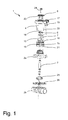
- a manual valve 1 in the form of a diaphragm valve with a multi-part valve main body 2 and a spindle 3 movably arranged therein.
- the valve main body 2 consists in this embodiment of a valve body 2a and a manual valve upper part 2b, which may be screwed together, for example.
- the spindle 3 can be adjusted relative to the valve main body 2 together with the handwheel 4 for actuating the manual valve 1 by means of a handwheel 4 arranged on the spindle 3 in its position. If, as shown, a right-handed thread is used for the adjustment, the manual valve 1 is closed by turning the handwheel 4 clockwise. By turning the handwheel 4 counterclockwise, the manual valve 1 is opened.
- a pressure piece 25 is arranged on the spindle 3, which acts on a membrane 26 in a conventional manner.
- a pressure piece 25 is arranged on the spindle 3, which acts on a membrane 26 in a conventional manner.
- a pressure piece 25 is arranged on the spind
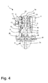
- the handwheel 4 has an integral threaded bushing 10, which is connected via three webs 11 with the handwheel 4.
- the spindle 3 is as in particular in the Figs. 3 . 4 . 6 and 7 to recognize screwed into the threaded bush 10.
- the manual valve 1 has a stroke limiter 5, which comprises a stop element in the form of a threaded nut 6 with external thread and a holder in the form of a threaded sleeve 7 with internal thread.
- the nut 6 is as in the Figs. 3 . 4 . 6 and 7 shown screwed into the threaded sleeve 7.
- the threaded sleeve 7 is arranged on the hand valve upper part 2b of the valve main body 2 and has three grooves 12 which are in positive engagement with the three webs 11 of the handwheel. Thus, the threaded sleeve 7 is also rotated upon rotation of the handwheel 4.
- the threaded sleeve 7 is - as will be described below - not in the operating direction of the spindle 3 movable. In other words, although the threaded sleeve 7 can be rotated relative to the valve main body 2, it can not be moved away from or toward it. A translational movement with respect to the valve main body 2 is therefore not possible.
- the position of the threaded nut 6 in the threaded sleeve 7 is changed by screwing in or out.
- the threaded nut 6 is screwed to the upper end of the threaded sleeve 7, so that a maximum stroke can be achieved.
- the nut 6 is as in the Figs. 3 and 4 shown further screwed into the threaded sleeve 7, so that a lower maximum stroke is achieved. If the handwheel 4 is actuated to open the manual valve 1, the handwheel 4 moves away together with the spindle 3 from the valve main body 2. In this case, although the threaded sleeve 7 is rotated, it is not moved away from the valve main body 2.
- the threaded nut 6 can be rotated relative to the threaded sleeve 7 and screwed into this via the actuating element 8 with dissolved rotary connection and in this.
- the actuating element 8 on four projections 13 which engage positively in corresponding recesses of the threaded nut 6.
- the manual valve 1 comprises a closing limit 9, which makes it possible to set the closed position of the spindle 3.
- the rotary joint between actuator 8 and handwheel 4 must also be solved.
- the spindle 3 can then be rotated relative to the handwheel 4.
- the handwheel 4 is first completely screwed in until the lower abutment surface 10b of the threaded bush 10 strikes the hand valve upper part 2b of the valve main body 2. If the handwheel 4 is now rotated further, only the spindle 3 is moved in position relative to the valve main body 2, but no longer the handwheel 4.
- By holding the actuator 8 and turning the handwheel 4 counterclockwise only the handwheel 4 in his Changed position to the valve main body 2, whereby the closed position can be changed in the other direction.
- connection between the spindle 3 and actuator 8 is performed by a two-edge connection, but other connection for power transmission are possible.
- a toothed connection 23 is provided which is no longer in connection with the toothed connection 23 of the handwheel 4 when the actuating element 8 is raised.
- the actuator 8 can be additionally secured by a locking screw 24 which is screwed into the spindle 3.
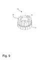
- the manual valve 1 has a visual display 15, which is covered by the handwheel 4 when the manual valve 1 is completely closed.
- the display 15 is fixedly arranged on the valve main body 2 and the manual valve upper part 2b and is visible when turning the handwheel 4 counterclockwise piece by piece. On the basis of the display 15 can then be determined at a glance, how far the manual valve 1 is open or closed.
- the display 15 has an at least partially circumferential projection 16, as can be seen in particular Fig. 9 can recognize well.
- This projection 16 fixes the threaded sleeve 7, so that while it is rotatable relative to the valve main body 2, but can not be moved away or away from this. This is necessary for the stroke limitation 5 described above, however, the threaded sleeve 7 could also be fixed via a clamping ring or the like, so that the visual display 15 is not mandatory.
- the display 15 has a plurality of circumferential locking grooves 18. These locking grooves 18 cooperate with a linearly guided on the handwheel 4 locking element 17, which can be moved parallel to the spindle 3. If that Latch member 17 is moved in the direction of the valve main body 2, engages the lower part of the locking element 17 in one of the locking grooves 18 of the display 15, so that rotation of the hand wheel 4 is no longer possible.
- the locking element 17 can be fixed in the engaged position, for example by a lock 19 (see. Fig. 8 ).
- the handwheel 4 has a first marking 20 and the visual display 15 has a second marking 21 at the position of the respective locking groove 18. As soon as the two markings 20, 21 are aligned, the locking element 17 can be inserted into the locking groove 18.
- the manual valve 1 is provided with a plurality of seals 22 between the individual elements.
- the seals 22 are designed as O-rings which sit in corresponding grooves.
- Gaskets 22 are provided between the display 15 and the valve main body 2 and hand valve upper part 2b, between the handwheel 4 and the display 15, between the actuator 8 and the handwheel 4 and between the locking screw 24 and the actuator 8.
- other seals are provided, such as between the valve body 2a and the hand valve upper part 2b.
Abstract
Description
- Die vorliegende Erfindung betrifft ein Handventil mit einem Ventilhauptkörper und einer darin zumindest in einer Betätigungsrichtung beweglich angeordneten Spindel, die zur Betätigung des Handventils mittels eines an der Spindel angeordneten Handrades in seiner Lage relativ zum Ventilhauptkörper zusammen mit dem Handrad verstellt werden kann, wobei das Handventil eine Hubbegrenzung für die Spindel mit einem Anschlagselement aufweist, das in seiner Lage in Bezug auf den Ventilhauptkörper einstellbar ist.
- Derartige Handventile werden auch als steigende Handventile bezeichnet. Bei steigenden Handventilen wird das Ventil durch Drehen des Handrads geöffnet bzw. geschlossen, wobei sich das Handrad gemeinsam mit der Spindel in Betätigungsrichtung entweder vom Ventilhauptkörper weg- oder zum Ventilhauptkörper hinbewegt. Die Betätigungsrichtung erstreckt sich also in Längsrichtung der Spindel. Im Gegensatz hierzu bewegt sich bei einem nicht-steigenden Handrad lediglich die Spindel, wobei das Handrad sich nicht vom Ventihauptlkörper hin- oder wegbewegt.
- Für viele Einsatzgebiete ist es zweckmäßig, derartige Handventile mit einer Hubbegrenzung auszustatten. Hierbei kann die maximale Öffnung des Handventils eingestellt werden, indem die Bewegung der Spindel entlang der Betätigungsrichtung bei einer öffnenden Bewegung begrenzt wird. In der Regel wird hierfür ein Anschlagselement verwendet, an welchem die Spindel oder ein anderes sich mit der Spindel bewegendes Teil anschlägt. Um den Hub zu begrenzen kann die Lage des Anschlagselements relativ zum Ventilhauptkörper eingestellt werden. Soll der Hub stärker begrenzt werden, wird der Abstand zwischen Anschlagselement und Ventilhauptkörper verringert. Entsprechend wird bei einem größeren Maximalhub der Abstand zwischen Ventilhauptkörper und Anschlagselement vergrößert.
- Bei nicht-steigenden Handventilen kann das Anschlagselement direkt am Handrad angeordnet werden, da das Handrad sich nicht mit der Spindel beim Betätigen bewegt und somit der Abstand zwischen Anschlagselement und Ventilhauptkörper konstant bleibt. Eine derartige Hubbegrenzung für ein nichtsteigendes Handrad ist beispielsweise in der
EP 1 257 755 B1 gezeigt. - Bei steigenden Handventilen ergibt sich aber das Problem, dass sich das Handrad mit der Spindel gemeinsam bewegt. Somit muss bei einer integrierten Hubbegrenzung das Anschlagselement zum Einstellen des Maximalhubs entweder direkt am Ventilhauptkörper angeordnet sein, oder der Ventilhauptkörper einen festen Anschlag für ein an der Spindel angeordnetes Anschlagselement aufweisen. Um das Anschlagselement schnell und einfach in seiner Lage verändern zu können, ergibt sich somit ein vergleichsweise großes Handventil, da das Anschlagselement zur Lagejustierung gut zugänglich sein muss, insbesondere dann, wenn ein Werkzeug zur Einstellung zu verwenden ist. Letzteres ist beispielsweise dann der Fall, wenn die Hubbegrenzung über eine Sechskantmutter bzw. -schraube oder dergleichen erfolgt.
- Ist jedoch ein kompakter Aufbau gewünscht, wird die Zugänglichkeit zum Anschlagselement eingeschränkt, wodurch die Hubbegrenzung nur unter großem Aufwand mit Spezialwerkzeug oder gar durch zumindest teilweise Demontage des Handventils einstellbar ist.
- Somit ist es Aufgabe der vorliegenden Erfindung ein kompaktes steigendes Handventil mit einer integrierten Hubbegrenzung aufzuzeigen, bei welchem der Maximalhub der Spindel schnell und einfach ohne großen Aufwand eingestellt werden kann.
- Die Lösung der Aufgabe gelingt mit einem Handventil gemäß Anspruch 1. Vorteilhafte Weiterbildungen sind in den Unteransprüchen beschrieben.
- Die vorliegende Erfindung zeichnet sich gegenüber den bekannten Handventilen dadurch aus, dass die Hubbegrenzung eine Halterung für das Anschlagselement aufweist, die mit dem Handrad drehbar aber in ihrer Lage zum Ventilhauptkörper in Betätigungsrichtung der Spindel fixiert am Ventilhauptkörper gehalten ist. Dabei ist die Halterung so ausgeführt, dass die Lage des Anschlagselements an der Halterung verändert werden kann, wobei die Halterung sich bei Betätigung des Handventils zwar mit dem Handrad und der Spindel mit dreht, sich jedoch nicht entlang der Betätigungsrichtung bewegt. Dies hat den Vorteil, dass eine im Handventil integrierte Hubbegrenzung geschaffen wird. Zudem kann das Anschlagselement zum Einstellen seiner Lage gut zugänglich angeordnet werden, sodass im besten Fall kein Werkzeug zu Einstellung der Hubbegrenzung nötig ist. Ferner kann durch die integrierte Ausführung der Hubbegrenzung die Abdichtung des Ventils bereits herstellerseitig optimiert werden, sodass sich eine im Vergleich zu Nachrüst-Hubbegrenzungen erheblich bessere Dichtheit ergibt und gleichzeitig ein kompakter Aufbau geschaffen wird. Unter einem Ventilhauptkörper im Sinne der Erfindung kann ein einteiliger oder mehrteiliger Körper verstanden werden. Insbesondere mehrteilige Ausführungen, beispielsweise mit einem Ventilkörper und einem Handventiloberteil, sind nicht zuletzt aus Wartungs- und Montagesicht zweckmäßig.
- Weiterbildend ist das Anschlagselement durch ein am Handrad angeordnetes Betätigungselement in seiner Lage in Bezug auf den Ventilhauptkörper einstellbar. Somit wird zum Einstellen der Lage des Anschlagselements kein gesondertes Werkzeug benötigt, da das Werkzeug im Handventil quasi integriert ist. Dies erleichtert Handhabbarkeit des Ventils und die Einstellbarkeit des Hubes nochmals merklich.
- Es ist zweckmäßig, wenn das Anschlagselement eine Gewindemutter mit einem Außengewinde ist, und die Halterung eine Gewindehülse mit einem Innengewinde ist. Durch Drehen der Gewindemutter bewegt sich diese entlang der Gewindegänge der Gewindehülse, wodurch diese besonders schnell und präzise in ihrer Lage in Bezug zum Ventilhauptkörper verändert werden kann.
- Es ist ferner von Vorteil, wenn das Handventil eine Schließbegrenzung aufweist, wobei zwischen Handrad und Spindel ein Kupplungselement angeordnet ist, um wahlweise die Drehverbindung von Handrad und Spindel auflösen oder herstellen zu können. Hierzu weist das Handrad zur Schließbegrenzung eine Gewindebuchse mit einem Innengewinde auf, wobei die Spindel mit ihrem Außengewinde in die Gewindebuchse eingeschraubt ist. Vorzugsweise ist die Gewindebuchse integral mit dem Handrad ausgeführt. Die Spindel ist bei gelöster Drehverbindung durch Drehung des Handrads relativ zum Handrad in Betätigungsrichtung zum Einstellen der Schließposition der Spindel bewegbar. Somit kann durch das Kupplungselement ermöglicht werden, dass die Spindel unabhängig vom Handrad gedreht werden kann. Wenn das Handrad in seiner maximalen Schließstellung weiter gedreht wird, bewegt sich die Spindel entlang der Betätigungsrichtung wodurch die maximale Schließposition eingestellt wird. Alternativ kann das Handrad auch unabhängig von der Spindel entlang der Betätigungsrichtung bewegt werden, wodurch die Schließstellung in die andere Richtung verändert werden kann. Wenn die gewünschte Schließstellung der Spindel somit erreicht ist, wird durch das Kupplungselement die Verbindung zwischen Handrad und Spindel wieder hergestellt, wodurch sich das Handrad wieder zusammen mit der Spindel zur Betätigung des Handventils drehen lässt. Dadurch wird eine integrierte aber von der Hubbegrenzung unabhängige Schließbegrenzung erreicht, durch welche die Schließstellung ohne großen Aufwand oder gesondertes Werkzeug eingestellt werden kann. Ferner muss so auch nach Betätigung der Schließbegrenzung oder der Hubbegrenzung die jeweils andere Begrenzung nicht nachjustiert werden.
- Zweckmäßigerweise ist das Betätigungselement für die Hubbegrenzung das Kupplungselement der Schließbegrenzung. So können mit einem einzigen Bauteil auf besonders kompakte Weise zwei unterschiedliche Funktionen umgesetzt werden. So kann bei gelöster Drehverbindung durch Drehung des Handrads die Schließbegrenzung betätigt werden, und durch Drehung des Betätigungs- bzw. Kupplungselements der Hub eingestellt werden. Hierdurch ergibt sich ein besonders kompakter Aufbau wobei sowohl die Schließ- als auch die Hubbegrenzung einfach und schnell zu betätigen sind.
- Zweckmäßigerweise schlägt die Gewindebuchse der Schließbegrenzung bei hergestellter Drehverbindung in der Schließposition der Spindel am Ventilhauptkörper an. Sobald die Gewindebuchse anschlägt, kann das Handrad nicht weiter betätigt werden, sodass das Handventil maximal geschlossen ist. Wenn nunmehr die Drehverbindung zwischen Kupplungs- bzw. Betätigungselement und Handrad gelöst wird, kann die Schließbegrenzung wie oben beschrieben eingestellt werden.
- Es ist von Vorteil, wenn das Handrad wenigstens einen Steg, vorzugsweise drei Stege, aufweist, wobei der wenigstens eine Steg formschlüssig in eine Nut der Halterung der Hubbegrenzung eingreift. Somit kann die Halterung bzw. die Gewindehülse der Hubbegrenzung über eine formschlüssige Verbindung gemeinsam mit dem Handrad in Drehung versetzt werden ohne dabei ein Seigen bzw. Senken des Handrades zu behindern.
- Weiterbildend ist der wenigstens eine Steg mit der Gewindebuchse verbunden. Somit kann die Gewindebuchse zusammen mit dem wenigstens einen Steg eine kompakte Einheit am Handrad bilden.
- Es ist zweckmäßig, wenn das Betätigungselement wenigstens einen Vorsprung, vorzugsweise vier Vorsprünge, aufweist, wobei der wenigstens eine Vorsprung formschlüssig in eine Ausnehmung des Anschlagselements eingreift. Diese sind bevorzugt als sich parallel zur Betätigungsrichtung erstreckende Längsstege ausgebildet, sodass sie auch bei unterschiedlichen Lagen des Anschlagselements mit diesem in Eingriff stehen und das Betätigungselement auch in leicht angehobener Stellung um Verstellen der Höhenlage des Anschlagselements betätigt - sprich per Hand - gedreht werden kann. Hierdurch ist das Betätigungselement drehfest mit dem Anschlagselement verbunden, wodurch die oben beschriebene Funktion zum Einstellen des Hubs einfach realisiert werden kann.
- Zweckmäßigerweise weist das Handventil eine am Ventilhauptkörper angeordnete Sichtanzeige auf, wobei die Sichtanzeige in der Schließposition der Spindel zumindest teilweise durch das Handrad verdeckt ist. Durch Betätigen des Handventils wird die Sichtanzeige entweder zu einem größeren Teil sichtbar (öffnende Bewegung in Betätigungsrichtung), oder weiter verdeckt (schließende Bewegung in Betätigungsrichtung). Hierdurch kann die Schließstellung des Ventils gut anhand der Sichtanzeige mit einem Blick abgelesen werden. Hierbei ist es von Vorteil, wenn die Sichtanzeige eine Skala aufweist, die die Beurteilung der Stellung vereinfacht.
- Es ist von Vorteil, wenn die Sichtanzeige einen zumindest teilweise umlaufenden Vorsprung aufweist, der die Halterung in ihrer Lage in Bezug zum Ventilhauptkörper fixiert. Hierdurch kann gewährleistet werden, dass die Halterung bzw. die Gewindehülse mit dem Handrad drehbar ist, sich aber gleichzeitig nicht in Betätigungsrichtung bewegen kann, insbesondere dann, wenn die Sichtanzeige am Ventilhauptkörper fixiert ist.
- Weiterbildend weist das Handventil ein verschiebliches und am Handrad geführtes Riegelelement auf, wobei der Ventilhauptkörper oder die Sichtanzeige eine Mehrzahl an Riegelnuten aufweist. Das Riegelelement ist in Eingriff mit einer der Riegelnuten bringbar, sodass das Handrad gegen Verdrehung gegenüber dem Ventilhauptkörper oder der Sichtanzeige gesichert ist. Hierdurch kann eine gewünschte Öffungs- bzw. Schließstellung des Handventils fixiert werden, sodass eine ungewollte oder ungewünschte Betätigung vermieden wird.
- Hierzu kann es zweckmäßig sein, wenn das Riegelelement in der Eingriffsposition, insbesondere durch ein Schloss oder dergleichen, gesichert werden kann. Dadurch kann ein Betätigen des Handventils sicher vermieden werden, um beispielsweise unbefugten Zugriff zu verhindern.
- Zweckmäßigerweise weist das Handrad eine erste Markierung und jede Riegelnut ein zweite Markierung auf, wobei das Riegelelement bei Fluchtung der ersten und zweiten Markierung in Eingriff mit der Riegelnuten bringbar ist. Dadurch wird gewährleistet, dass das Riegelelement sicher in eine Riegelnut einzuführen ist und die gewünschte Stellung des Handventils gesichert werden kann.
- Es ist von Vorteil, wenn zwischen dem Ventilhauptkörper und der Sichtanzeige und/oder zwischen der Sichtanzeige und/oder zwischen dem Betätigungselement und dem Handrad wenigstens eine Dichtung angeordnet ist. Somit kann eine größtmögliche Dichtheit des gesamten Handventils erreicht werden. Dies spielt beispielsweise bei der Reinigung des Handventils eine große Rolle, da bei einer unzureichenden Dichtheit die Schmierung der Spindel über die Zeit ausgewaschen werden kann, wodurch es unter Umständen zu Beschädigungen oder Funktionsverlusten kommen kann. Gerade bei kombinierter Hub- und Schließbegrenzung ist so eine für ein steigendes Handventil außergewöhnlich gute Abdichtung und damit Langlebigkeit erzielbar. Auch wird so ein Eindringen von Feuchtigkeit oder Schmutz zuverlässig verhindert.
- Es ist zweckmäßig, wenn die Drehverbindung zwischen Handrad und Spindel eine Zahnverbindung ist. Insbesondere greift also das Kupplungselement bzw. das Betätigungselement über eine Zahnverbindung formschlüssig am Handrad an, sodass bei in Eingriff gebrachter Zahnverbindung eine sichere Kraftübertragung vom Handrad auf die Spindel gewährleistet werden kann. Hierbei kann die Zahnverbindung in Form eines am Kupplungselement angebrachten Zahnkranzes ausgestaltet sein, der zweckmäßigerweise eine recht feine Zahnstruktur aufweist, um so eine feiner Justierung zu ermöglichen.
- Weiterbildend ist das Betätigungselement über eine Sicherungsschraube mit der Spindel verschraubt. Die Spindel kann beispielsweise über eine Zweikant- oder Feder/Nut-Verbindung mit dem Betätigungselement in Eingriff stehen, wobei das Betätigungselement durch eine Schraube an der Spindel gesichert ist. Somit kann das Betätigungselement nicht versehentlich betätigt werden, da zunächst die Schraube zu lösen wäre.
- Hierbei ist es auch von Vorteil, wenn zwischen Sicherungsschraube und Betätigungselement wenigstens eine Dichtung angeordnet ist. Dadurch wird die Dichtheit des Handventils weiter erhöht, sodass es nicht zum Eindringen von Feuchtigkeit, Schmutz oder dergleichen kommen kann.
- Nachfolgend wird die Erfindung anhand eines in der Zeichnung dargestellten Ausführungsbeispiels näher erläutert. Hierbei zeigen schematisch:
- Fig. 1
- eine Explosionsdarstellung des erfindungsgemäßen Handventils;
- Fig. 2
- eine perspektivische Ansicht eines erfindungsgemäßen Handventils mit Hubbegrenzung in einer ersten Stellung;
- Fig. 3
- einen Schnitt durch das in
Fig. 2 gezeigte Handventil entlang der Anschlussrichtung des Handventils; - Fig. 4
- einen Schnitt durch das in
Fig. 2 gezeigte Handventil orthogonal zur Anschlussrichtung des Handventils; - Fig. 5
- eine perspektivische Ansicht eines erfindungsgemäßen Handventils mit Hubbegrenzung in einer zweiten Stellung;
- Fig. 6
- einen Schnitt durch das in
Fig. 5 gezeigte Handventil entlang der Anschlussrichtung des Handventils; - Fig. 7
- einen Schnitt durch das in
Fig. 5 gezeigte Handventil orthogonal zur Anschlussrichtung des Handventils; - Fig. 8
- eine perspektivische Ansicht des erfindungsgemäßen Handventils ohne Handrad; und
- Fig. 9
- eine perspektivische Ansicht der Sichtanzeige.
- In den
Figuren 1 bis 7 ist ein Handventil 1 in Form eines Membranventils mit einem mehrteiligen Ventilhauptkörper 2 und einer darin beweglich angeordneten Spindel 3 dargestellt. Der Ventilhauptkörper 2 besteht in diesem Ausführungsbeispiel aus einem Ventilkörper 2a sowie einem Handventiloberteil 2b, die beispielsweise miteinander verschraubt sein können. Die Spindel 3 kann zur Betätigung des Handventils 1 mittels eines an der Spindel 3 angeordneten Handrads 4 in seiner Lage relativ zum Ventilhauptkörper 2 zusammen mit dem Handrad 4 verstellt werden. Wird wie dargestellt ein rechtsdrehendes Gewinde zur Verstellung verwendet, so wird durch Drehung des Handrads 4 im Uhrzeigersinn das Handventil 1 geschlossen. Durch Drehung des Handrades 4 gegen den Uhrzeigersinn wird das Handventil 1 geöffnet. Um das Handventil 1 zu schließen ist an der Spindel 3 ein Druckstück 25 angeordnet, welches auf eine Membran 26 in herkömmlicher Art und Weise einwirkt. Selbstverständlich sind auch Ausführungen mit einem Linksgewinde denkbar. - Ferner weist das Handrad 4 eine integrale Gewindebuchse 10 auf, die über drei Stege 11 mit dem Handrad 4 verbunden ist. Die Spindel 3 ist wie insbesondere in den
Figs. 3 ,4 ,6 und7 zu erkennen in die Gewindebuchse 10 eingeschraubt. - Das Handventil 1 weist eine Hubbegrenzung 5 auf, die ein Anschlagselement in Form einer Gewindemutter 6 mit Außengewinde und eine Halterung in Form einer Gewindehülse 7 mit Innengewinde umfasst. Die Gewindemutter 6 ist wie in den
Figs. 3 ,4 ,6 und7 dargestellt in die Gewindehülse 7 eingeschraubt. Die Gewindehülse 7 ist am Handventiloberteil 2b des Ventilhauptkörpers 2 angeordnet und weist drei Nuten 12 auf, die mit den drei Stegen 11 des Handrads in formschlüssigen Eingriff stehen. Somit wird die Gewindehülse 7 bei Drehung des Handrads 4 ebenfalls gedreht. Die Gewindehülse 7 ist - wie nachfolgende beschrieben wird - nicht in der Betätigungsrichtung der Spindel 3 beweglich. Mit anderen Worten kann die Gewindehülse 7 zwar gegenüber dem Ventilhauptkörper 2 gedreht werden, aber nicht von diesem weg- oder zu diesem hinbewegt werden. Eine translatorische Bewegung in Bezug auf den Ventilhauptkörper 2 ist also nicht möglich. - Um den Hub zu verändern wird die Lage der Gewindemutter 6 in der Gewindehülse 7 durch ein- bzw. ausschrauben verändert. In den
Figs. 6 und7 ist die Gewindemutter 6 ans obere Ende der Gewindehülse 7 geschraubt, sodass ein maximaler Hub erreicht werden kann. Im Gegensatz hierzu ist die Gewindemutter 6 wie in denFigs. 3 und4 dargestellt weiter in die Gewindehülse 7 eingeschraubt, sodass ein geringerer Maximalhub erzielt wird. Wird das Handrad 4 zum Öffnen des Handventils 1 betätigt, entfernt sich das Handrad 4 mitsamt der Spindel 3 vom Ventilhauptkörper 2. Hierbei wird die Gewindehülse 7 zwar mitgedreht, jedoch wird diese nicht vom Ventilhauptkörper 2 wegbewegt. Mithin bleibt der eingestellte Abstand zwischen Gewindemutter 6 und Ventilhauptkörper 2 konstant. Sobald die Gewindebuchse 10 mit der oberen Anschlagsfläche 10a an der Gewindemutter 6 anschlägt, kann das Handrad 4 nicht weiter betätigt werden, sodass der Hub der Spindel 3 also entsprechend begrenzt ist. - Zum ein- und ausschrauben der Gewindemutter 6 weist das Handventil 1 ein Betätigungs- bzw. Kupplungselement 8 auf, welches zum einen dazu dient, eine Drehverbindung zwischen Handrad 4 und Spindel 3 herstellen und auflösen zu können. Zum anderen kann über das Betätigungselement 8 bei gelöster Drehverbindung die Gewindemutter 6 relativ zur Gewindehülse 7 gedreht und in diese ein- bzw. ausgeschraubt werden. Hierfür weist das Betätigungselement 8 vier Vorsprünge 13 auf, die formschlüssig in entsprechende Ausnehmungen der Gewindemutter 6 eingreifen. Somit wird durch eine Drehung des Betätigungselements 8 relativ zum Handrad 4 die Gewindemutter 6 relativ zur Gewindehülse 7 bewegt, da die Gewindehülse 7 drehfest mit dem Handrad 4 verbunden ist. Dadurch kann der gewünschte Hub eingestellt werden.
- Ferner umfasst das Handventil 1 eine Schließbegrenzung 9, die es ermöglicht die Schließstellung der Spindel 3 einzustellen. Hierzu muss ebenfalls die Drehverbindung zwischen Betätigungselement 8 und Handrad 4 gelöst werden. Die Spindel 3 kann dann relativ zum Handrad 4 gedreht werden. Hierzu wird das Handrad 4 zunächst vollständig eingeschraubt, bis die untere Anschlagsfläche 10b der Gewindebuchse 10 am Handventiloberteil 2b des Ventilhauptkörpers 2 anschlägt. Wird das Handrad 4 nun weiter gedreht, wird nur noch die Spindel 3 in ihrer Lage relativ zum Ventilhauptkörper 2 bewegt, aber nicht mehr das Handrad 4. Durch Festhalten des Betätigungselements 8 und Drehung des Handrads 4 gegen den Uhrzeigesinn wird nur das Handrad 4 in seiner Lage zum Ventilhauptkörper 2 verändert, wodurch die Schließstellung in die andere Richtung verändert werden kann. Hierbei ist es wichtig, dass die formschlüssige Verbindung zwischen Spindel 3 und Betätigungselement 8 wie in den
Figs. 3 ,4 ,6 und7 dargestellt ausreichend Bewegungsraum bietet, sodass die Spindel 3 je nachdem welche Schließstellung eingestellt wird, tiefer in das Betätigungselements 8 eingeführt wird bzw. aus diesem ausgeführt wird, ohne dass der Formschluss zwischen Spindel 3 und Betätigungselement 8 aufgelöst wird. In diesem Ausführungsbeispiel ist die Verbindung zwischen Betätigungselement 8 und Spindel 3 durch eine Zweikantverbindung ausgeführt, jedoch sind auch andere Verbindung zur Kraftübertragung möglich. - Um die Drehverbindung zwischen Betätigungselement 8 und Handrad 4 herstellen und auflösen zu können, ist eine Zahnverbindung 23 vorgesehen, die bei angehobenen Betätigungselement 8 nicht mehr in Verbindung mit der Zahnverbindung 23 des Handrad 4 steht. Somit kann in diesem Fall keine Drehkraft vom Handrad 4 mehr auf die Spindel 3 übertragen werden. In diesem Ausführungsbeispiel kann das Betätigungselement 8 noch zusätzlich durch eine Sicherungsschraube 24 gesichert werden, welche in die Spindel 3 eingeschraubt ist.
- Ferner weist das Handventil 1 eine Sichtanzeige 15 auf, die bei vollständig geschlossenem Handventil 1 durch das Handrad 4 verdeckt wird. Die Sichtanzeige 15 ist ortsfest am Ventilhauptkörper 2 bzw. am Handventiloberteil 2b angeordnet und wird bei Drehung des Handrads 4 gegen den Uhrzeigersinn Stück für Stück sichtbar. Anhand der Sichtanzeige 15 kann dann mit einem Blick festgestellt werden, wie weit das Handventil 1 geöffnet oder geschlossen ist.
- Des Weiteren weist die Sichtanzeige 15 eine zumindest teilweise umlaufenden Vorsprung 16 auf, wie man insbesondere in
Fig. 9 gut erkennen kann. Dieser Vorsprung 16 fixiert die Gewindehülse 7, sodass diese zwar drehbar gegenüber dem Ventilhauptkörper 2 ist, aber nicht von diesem hin- oder wegbewegt werden kann. Diese ist für die oben beschriebene Hubbegrenzung 5 notwendig, jedoch könnte die Gewindehülse 7 auch über einen Klemmring oder dergleichen festgelegt werden, sodass die Sichtanzeige 15 nicht zwingend vorzusehen ist. - Des Weiteren kann man in
Figs. 8 und9 gut erkennen, dass die Sichtanzeige 15 eine Vielzahl an umlaufenden Riegelnuten 18 aufweist. Diese Riegelnuten 18 wirken mit einem am Handrad 4 linear geführten Riegelelement 17 zusammen, welches parallel zur Spindel 3 bewegt werden kann. Wenn das Riegelelement 17 in Richtung des Ventilhauptkörpers 2 bewegt wird, greift der untere Teil des Riegelelements 17 in eine der Riegelnuten 18 des Sichtanzeige 15 ein, sodass eine Drehung des Handrads 4 nicht mehr möglich ist. Das Riegelelement 17 kann in der Eingriffsstellung beispielsweise durch ein Schloss 19 fixiert werden (vgl.Fig. 8 ). - Damit das Riegelelement 17 passend in eine der Riegelnuten 18 eingeführt werden kann, weist das Handrad 4 einer erste Markierung 20 auf und die Sichtanzeige 15 an der Position der jeweiligen Riegelnut 18 eine zweite Markierung 21 auf. Sobald die beiden Markierungen 20, 21 fluchten, kann das Riegelelement 17 in die Riegelnut 18 eingeführt werden.
- Um eine ausreichende Dichtheit zu gewährleisten ist das Handventil 1 mit einer Vielzahl an Dichtungen 22 zwischen den einzelnen Elementen versehen. In diesem Ausführungsbeispiel sind die Dichtungen 22 als O-Ringe die in entsprechenden Nuten sitzen ausgeführt. Dichtungen 22 sind zwischen der Sichtanzeige 15 und dem Ventilhauptkörper 2 bzw. Handventiloberteil 2b, zwischen dem Handrad 4 und der Sichtanzeige 15, zwischen dem Betätigungselement 8 und dem Handrad 4 sowie zwischen der Sicherungsschraube 24 und dem Betätigungselement 8 vorgesehen. Selbstverständlich sind auch weitere Dichtungen vorgesehen, so beispielsweise zwischen dem Ventilkörper 2a und dem Handventiloberteil 2b.
-
- 1
- Handventil
- 2
- Ventilhauptkörper
- 2a
- Ventilkörper
- 2b
- Handventiloberteil
- 3
- Spindel
- 4
- Handrad
- 5
- Hubbegrenzung
- 6
- Gewindemutter (Anschlagselement)
- 7
- Gewindehülse (Halterung)
- 8
- Betätigungselement (Kupplungselement)
- 9
- Schließbegrenzung
- 10
- Gewindebuchse
- 10a
- obere Anschlagsfläche
- 10b
- untere Anschlagsfläche
- 11
- Steg
- 12
- Nut der Gewindehülse
- 13
- Vorsprung des Betätigungselements
- 14
- Ausnehmung der Gewindemutter
- 15
- Sichtanzeige
- 16
- Vorsprung der Sichtanzeige
- 17
- Riegelelement
- 18
- Riegelnut
- 19
- Schloss
- 20
- erste Markierung
- 21
- zweite Markierung
- 22
- Dichtung
- 23
- Zahnverbindung
- 24
- Sicherungsschraube
- 25
- Druckstück
- 26
- Membran
Claims (20)
- Handventil (1) mit einem Ventilhauptkörper (2) und einer darin zumindest in einer Betätigungsrichtung beweglich angeordneten Spindel (3), die zur Betätigung des Handventils mittels eines an der Spindel (3) angeordneten Handrades (4) in seiner Lage relativ zum Ventilhauptkörper (2) zusammen mit dem Handrad (4) verstellt werden kann, wobei das Handventil (1) eine Hubbegrenzung (5) für die Spindel (3) mit einem Anschlagselement (6) aufweist, das in seiner Lage in Bezug auf den Ventilhauptkörper (2) einstellbar ist,
dadurch gekennzeichnet, dass
die Hubbegrenzung (5) eine Halterung (7) für das Anschlagselement (6) aufweist, die mit dem Handrad (4) drehbar aber in ihrer Lage zum Ventilhauptkörper (2) in Betätigungsrichtung der Spindel (3) fixiert am Ventilhauptkörper (2) gehalten ist. - Handventil (1) nach Anspruch 1,
dadurch gekennzeichnet, dass
das Anschlagselement (6) durch ein am Handrad (4) angeordnetes Betätigungselement (8) in seiner Lage an der Halterung (7) in Bezug auf den Ventilhauptkörper (2) einstellbar ist. - Handventil (1) nach Anspruch 1 oder 2,
dadurch gekennzeichnet, dass
das Anschlagselement (6) eine Gewindemutter mit einem Außengewinde ist, und die Halterung (7) eine Gewindehülse mit einem Innengewinde ist. - Handventil (1) nach einem der vorhergehenden Ansprüche,
dadurch gekennzeichnet, dass
das Handventil (1) eine Schließbegrenzung (9) aufweist, wobei zwischen Handrad (4) und Spindel (3) ein Kupplungselement (8) angeordnet ist, um wahlweise die Drehverbindung von Handrad (4) und Spindel (3) auflösen oder herstellen zu können;
und das Handrad (4) zur Schließbegrenzung eine Gewindebuchse (10) mit einem Innengewinde aufweist, wobei die Spindel (3) mit ihrem Außengewinde in die Gewindebuchse (10) eingeschraubt ist,
und die Spindel (3) bei gelöster Drehverbindung durch Drehung des Handrads (4) relativ zum Handrad (4) in Betätigungsrichtung zum Einstellen der Schließposition der Spindel (3) bewegbar ist. - Handventil (1) nach Anspruch 4,
dadurch gekennzeichnet, dass
das Kupplungselement (8) der Schließbegrenzung (9) auch das Betätigungselement (8) der Hubbegrenzung (5) ist. - Handventil (1) nach Anspruch 4 oder 5,
dadurch gekennzeichnet, dass
die Gewindebuchse (10) bei hergestellter Drehverbindung in der Schließposition der Spindel (3) am Ventilhauptkörper (2) anschlägt. - Handventil (1) nach einem der vorhergehenden Ansprüche,
dadurch gekennzeichnet, dass
das Handrad (4) wenigstens einen Steg (11), vorzugsweise drei Stege (11), aufweist, wobei der wenigstens eine Steg (11) formschlüssig in eine Nut (12) der Halterung (7) eingreift. - Handventil (1) nach Anspruch 7,
dadurch gekennzeichnet, dass
der wenigstens eine Steg (11) mit der Gewindebuchse (10) verbunden ist. - Handventil (1) nach einem der vorhergehenden Ansprüche 2 bis 8,
dadurch gekennzeichnet, dass
das Betätigungselement (8) wenigstens einen Vorsprung (13), vorzugsweise vier Vorsprünge (13), aufweist, wobei der wenigstens eine Vorsprung (13) formschlüssig in eine Ausnehmung (14) des Anschlagselements (6) eingreift. - Handventil (1) nach einem der vorhergehenden Ansprüche,
dadurch gekennzeichnet, dass
das Handventil (1) eine am Ventihauptlkörper (2) angeordnete Sichtanzeige (15) aufweist, wobei die Sichtanzeige (15) in der Schließposition der Spindel (3) zumindest teilweise durch das Handrad (4) verdeckt ist. - Handventil (1) nach Anspruch 10,
dadurch gekennzeichnet, dass
die Sichtanzeige (15) einen zumindest teilweise umlaufenden Vorsprung (16) aufweist, wobei der Vorsprung (16) die Halterung (7) in ihrer Lage in Bezug zum Ventilhauptkörper (2) fixiert. - Handventil (1) nach einem der vorhergehenden Ansprüche,
dadurch gekennzeichnet, dass
das Handventil (1) ein verschiebliches und am Handrad (4) geführtes Riegelelement (17) aufweist,
wobei der Ventilhauptkörper (2) oder die Sichtanzeige (15) eine Mehrzahl an Riegelnuten (18) aufweist,
wobei das Riegelelement (17) in Eingriff mit einer der Riegelnuten (18) bringbar ist, sodass das Handrad (4) gegen Verdrehung gegenüber dem Ventilhauptkörper (2) oder der Sichtanzeige (15) gesichert ist. - Handventil (1) nach Anspruch 12,
dadurch gekennzeichnet, dass
das Riegelelement (17) in der Eingriffsposition, insbesondere durch ein Schloss (19) oder dergleichen, gesichert werden kann. - Handventil (1) nach einem der Ansprüche 10 bis 13,
dadurch gekennzeichnet, dass
das Handrad (4) eine erste Markierung (20) aufweist,
und jede Riegelnut (18) ein zweite Markierung (21) aufweist,
wobei das Riegelelement (17) bei Fluchtung der ersten und zweiten Markierung (20, 21) in Eingriff mit der Riegelnuten (18) bringbar ist. - Handventil (1) nach einem der vorhergehenden Ansprüche 10 bis 14,
dadurch gekennzeichnet, dass
zwischen dem Ventilhauptkörper (2) und der Sichtanzeige (15) wenigstens eine Dichtung (22) angeordnet ist. - Handventil (1) nach einem der vorhergehenden Ansprüche 10 bis 15,
dadurch gekennzeichnet, dass
zwischen der Sichtanzeige (15) und dem Handrad (4) wenigstens eine Dichtung (22) angeordnet ist. - Handventil (1) nach einem der vorhergehenden Ansprüche 2 bis 16,
dadurch gekennzeichnet, dass
zwischen dem Betätigungselement (8) und dem Handrad (4) wenigstens eine Dichtung (22) angeordnet ist. - Handventil (1) nach einem der vorhergehenden Ansprüche 4 bis 17,
dadurch gekennzeichnet, dass
die Drehverbindung zwischen Handrad (4) und Spindel (3) eine Zahnverbindung (23) ist. - Handventil (1) nach einem der Ansprüche 2 bis 18,
dadurch gekennzeichnet, dass
das Betätigungselement (8) über eine Sicherungsschraube (24) mit der Spindel (3) verschraubt ist. - Handventil (1) nach Anspruch 19,
dadurch gekennzeichnet, dass
zwischen Sicherungsschraube (24) und Betätigungselement (8) wenigstens eine Dichtung (22) angeordnet ist.
Applications Claiming Priority (1)
| Application Number | Priority Date | Filing Date | Title |
|---|---|---|---|
| DE102012109756.9A DE102012109756B4 (de) | 2012-10-12 | 2012-10-12 | Steigendes Handventil mit Hubbegrenzung |
Publications (2)
| Publication Number | Publication Date |
|---|---|
| EP2719932A1 true EP2719932A1 (de) | 2014-04-16 |
| EP2719932B1 EP2719932B1 (de) | 2017-01-04 |
Family
ID=49382272
Family Applications (1)
| Application Number | Title | Priority Date | Filing Date |
|---|---|---|---|
| EP13188512.1A Active EP2719932B1 (de) | 2012-10-12 | 2013-10-14 | Steigendes Handventil mit Hubbegrenzung |
Country Status (3)
| Country | Link |
|---|---|
| US (1) | US9458948B2 (de) |
| EP (1) | EP2719932B1 (de) |
| DE (1) | DE102012109756B4 (de) |
Cited By (2)
| Publication number | Priority date | Publication date | Assignee | Title |
|---|---|---|---|---|
| CN106885042A (zh) * | 2017-04-17 | 2017-06-23 | 上海阀门五厂有限公司 | 一种可实现上密封的隔膜阀阀盖组件 |
| US11499642B2 (en) | 2020-04-15 | 2022-11-15 | Festo Se & Co. Kg | Pressure actuated valve with shock absorber |
Families Citing this family (12)
| Publication number | Priority date | Publication date | Assignee | Title |
|---|---|---|---|---|
| CN105659011B (zh) * | 2013-08-02 | 2017-12-08 | 株式会社开滋 | 铁路车辆用急速排气阀和铁路车辆的配管系统 |
| JP2017503123A (ja) * | 2013-11-28 | 2017-01-26 | ハム−レット (イスラエル−カナダ) リミテッド | 流体の流れを制御および調整するための弁装置 |
| WO2016093271A1 (ja) * | 2014-12-11 | 2016-06-16 | 株式会社キッツ | 回転弁と鉄道車両用急速排気弁 |
| CN106090415B (zh) * | 2016-07-26 | 2018-07-13 | 中国石油天然气股份有限公司 | 一种防盗装置及角行程阀门 |
| KR102254663B1 (ko) * | 2017-07-31 | 2021-05-21 | 가부시끼가이샤후지킨 | 가스 공급 시스템 |
| DE102018213711A1 (de) * | 2018-08-15 | 2020-02-20 | Festo Ag & Co. Kg | Ventil |
| DE102018213712B4 (de) * | 2018-08-15 | 2020-10-08 | Festo Se & Co. Kg | Ventilanordnung |
| CN113614429B (zh) * | 2019-02-20 | 2023-07-28 | Itt制造企业有限责任公司 | 隔膜组件 |
| ES2953306T3 (es) * | 2019-05-29 | 2023-11-10 | Fischer G Rohrleitungssysteme Ag | Puesta en marcha de válvula de diafragma |
| DE102019129059A1 (de) * | 2019-10-28 | 2021-04-29 | Grohe Ag | Ventil für eine Sanitärarmatur mit einem Membranventil und einem einstellbaren Steuerstab |
| JP7448368B2 (ja) | 2020-02-10 | 2024-03-12 | 株式会社キッツエスシーティー | 手動用ダイヤフラムバルブ |
| KR102461941B1 (ko) * | 2021-08-11 | 2022-11-03 | 안희준 | 컨덕턴스 조절이 가능한 진공밸브 |
Citations (7)
| Publication number | Priority date | Publication date | Assignee | Title |
|---|---|---|---|---|
| FR1103790A (fr) * | 1954-04-24 | 1955-11-07 | Salvi Ets | Robinet à double réglage, en particulier pour radiateurs de chauffage central |
| FR1482169A (fr) * | 1966-04-06 | 1967-05-26 | Term | Perfectionnements aux vannes à double réglage pour chauffage central et applications analogues |
| US3347270A (en) * | 1965-03-11 | 1967-10-17 | Stile Craft Mfg Inc | Pressure equalizing flow control valve |
| US3565089A (en) * | 1969-01-21 | 1971-02-23 | Elkhart Brass Mfg Co | Valve |
| FR2228996A1 (en) * | 1973-05-11 | 1974-12-06 | Blanchard Ateliers | Manually operated valve with optimum flow indicator - collar on spindle contacts adjustable stop to limit flow |
| EP0387634A1 (de) * | 1989-03-13 | 1990-09-19 | KSB Aktiengesellschaft | Armatur mit Hubbegrenzung |
| EP1257755B1 (de) | 2000-02-12 | 2005-06-01 | GEMÜ Gebrüder Müller Apparatebau GmbH & Co. KG | Handantrieb für absperrorgane |
Family Cites Families (12)
| Publication number | Priority date | Publication date | Assignee | Title |
|---|---|---|---|---|
| US2599286A (en) * | 1946-06-07 | 1952-06-03 | Mason Neilan Regulator Company | Valve position indicator |
| DE1853050U (de) * | 1962-03-28 | 1962-06-07 | Waldenmaier J E H | Membranventil fuer aggressive madien. |
| DE1600813B2 (de) * | 1967-06-29 | 1971-09-02 | Herion Werke KG, 7012 Fellbach | Drosselventil |
| US3712587A (en) * | 1971-05-12 | 1973-01-23 | American La France Inc | Flow restricting valve |
| US3831621A (en) * | 1973-11-19 | 1974-08-27 | Union Brass & Metal Mfg | Rotary slide valve |
| DE3212792C2 (de) * | 1982-04-06 | 1985-04-04 | Klein, Schanzlin & Becker Ag, 6710 Frankenthal | Stellungsanzeiger mit Feststellvorrichtung für Absperrarmaturen |
| DE4302556A1 (de) * | 1993-01-29 | 1994-08-04 | Mueller Apparatebau Gmbh & Co | Membranventil mit Schließhubbegrenzung |
| US5823509A (en) * | 1997-07-11 | 1998-10-20 | Amcast Industrial Corporation | Diaphragm valve with means for adjustably setting the maxium valve opening |
| US6241213B1 (en) * | 2000-03-07 | 2001-06-05 | Itt Manufacturing Enterprises, Inc. | Diaphragm valve |
| JP2006153042A (ja) * | 2004-11-25 | 2006-06-15 | Surpass Kogyo Kk | 流量調節弁 |
| KR100980237B1 (ko) * | 2005-12-02 | 2010-09-09 | 씨케이디 가부시키 가이샤 | 유량조정밸브 |
| DE202010008574U1 (de) * | 2010-09-17 | 2010-12-23 | Sed Flow Control Gmbh | Membranventil mit einer kombinierten Hub-Schließbegrenzung |
-
2012
- 2012-10-12 DE DE102012109756.9A patent/DE102012109756B4/de active Active
-
2013
- 2013-10-14 EP EP13188512.1A patent/EP2719932B1/de active Active
- 2013-10-15 US US14/054,259 patent/US9458948B2/en active Active
Patent Citations (7)
| Publication number | Priority date | Publication date | Assignee | Title |
|---|---|---|---|---|
| FR1103790A (fr) * | 1954-04-24 | 1955-11-07 | Salvi Ets | Robinet à double réglage, en particulier pour radiateurs de chauffage central |
| US3347270A (en) * | 1965-03-11 | 1967-10-17 | Stile Craft Mfg Inc | Pressure equalizing flow control valve |
| FR1482169A (fr) * | 1966-04-06 | 1967-05-26 | Term | Perfectionnements aux vannes à double réglage pour chauffage central et applications analogues |
| US3565089A (en) * | 1969-01-21 | 1971-02-23 | Elkhart Brass Mfg Co | Valve |
| FR2228996A1 (en) * | 1973-05-11 | 1974-12-06 | Blanchard Ateliers | Manually operated valve with optimum flow indicator - collar on spindle contacts adjustable stop to limit flow |
| EP0387634A1 (de) * | 1989-03-13 | 1990-09-19 | KSB Aktiengesellschaft | Armatur mit Hubbegrenzung |
| EP1257755B1 (de) | 2000-02-12 | 2005-06-01 | GEMÜ Gebrüder Müller Apparatebau GmbH & Co. KG | Handantrieb für absperrorgane |
Cited By (2)
| Publication number | Priority date | Publication date | Assignee | Title |
|---|---|---|---|---|
| CN106885042A (zh) * | 2017-04-17 | 2017-06-23 | 上海阀门五厂有限公司 | 一种可实现上密封的隔膜阀阀盖组件 |
| US11499642B2 (en) | 2020-04-15 | 2022-11-15 | Festo Se & Co. Kg | Pressure actuated valve with shock absorber |
Also Published As
| Publication number | Publication date |
|---|---|
| US9458948B2 (en) | 2016-10-04 |
| EP2719932B1 (de) | 2017-01-04 |
| US20140131607A1 (en) | 2014-05-15 |
| DE102012109756A1 (de) | 2014-04-17 |
| DE102012109756B4 (de) | 2015-01-08 |
Similar Documents
| Publication | Publication Date | Title |
|---|---|---|
| EP2719932B1 (de) | Steigendes Handventil mit Hubbegrenzung | |
| EP2942458B1 (de) | Kabelverriegelungssystem | |
| WO2012034860A1 (de) | Drehspannverschluss mit erkennbarkeit der verschlussstellung | |
| EP3084277A1 (de) | Hydraulische ventileinrichtung | |
| DE202014101096U1 (de) | Ventiloberteil | |
| DE7710413U1 (de) | Vorrichtung zur anzeige der stellung eines betaetigungsgliedes | |
| EP3447346A1 (de) | Ventil, insbesondere servoventil | |
| EP2041852B1 (de) | Schalter mit einer kupplung zur befestigung einer betätigungsvorrichtung | |
| EP3062002A1 (de) | Ventiloberteil | |
| DE102013105165B4 (de) | Betätigungsvorsatz zur Betätigung eines Tasters und/oder Schalters | |
| DE102012020909B3 (de) | Anordnung zur Drehmomentverstellung für einen Schraubendreher | |
| DE102008024363B4 (de) | Absperrhahn | |
| EP2354608A1 (de) | Ventilkartusche für eine Sanitärarmatur | |
| DE102019123485A1 (de) | Öffnungs- und Schliessventil | |
| DE102006050664B4 (de) | Betätigungsvorrichtung für ein Ventil | |
| DE102010039678B4 (de) | Stelleinrichtung für ein Ventil | |
| EP2226541B1 (de) | Betätigungsanordnung für Sanitärarmaturen | |
| EP1527295A1 (de) | Drei-wege-kugelhahn | |
| DE102010007952B4 (de) | Verschluss für eine Tür eines Gargeräts | |
| EP1793150A1 (de) | Absperrvorrichtung, insbesondere für Druckleitungen | |
| EP3001081A1 (de) | Eckventil mit Handrad | |
| DE19951580B4 (de) | Absperrarmatur | |
| DE3901284A1 (de) | Ventil | |
| DE202010008574U1 (de) | Membranventil mit einer kombinierten Hub-Schließbegrenzung | |
| EP3537017A1 (de) | Ventil |
Legal Events
| Date | Code | Title | Description |
|---|---|---|---|
| PUAI | Public reference made under article 153(3) epc to a published international application that has entered the european phase |
Free format text: ORIGINAL CODE: 0009012 |
|
| AK | Designated contracting states |
Kind code of ref document: A1 Designated state(s): AL AT BE BG CH CY CZ DE DK EE ES FI FR GB GR HR HU IE IS IT LI LT LU LV MC MK MT NL NO PL PT RO RS SE SI SK SM TR |
|
| AX | Request for extension of the european patent |
Extension state: BA ME |
|
| 17P | Request for examination filed |
Effective date: 20141013 |
|
| RBV | Designated contracting states (corrected) |
Designated state(s): AL AT BE BG CH CY CZ DE DK EE ES FI FR GB GR HR HU IE IS IT LI LT LU LV MC MK MT NL NO PL PT RO RS SE SI SK SM TR |
|
| REG | Reference to a national code |
Ref country code: DE Ref legal event code: R079 Free format text: PREVIOUS MAIN CLASS: F16K0031500000 Ipc: F16K0017160000 |
|
| RIC1 | Information provided on ipc code assigned before grant |
Ipc: F16K 35/06 20060101ALI20160429BHEP Ipc: F16K 7/12 20060101ALI20160429BHEP Ipc: F16K 31/50 20060101AFI20160429BHEP Ipc: F16K 1/52 20060101ALI20160429BHEP |
|
| GRAP | Despatch of communication of intention to grant a patent |
Free format text: ORIGINAL CODE: EPIDOSNIGR1 |
|
| RIC1 | Information provided on ipc code assigned before grant |
Ipc: F16K 31/50 20060101ALI20160607BHEP Ipc: F16K 7/16 20060101ALI20160607BHEP Ipc: F16K 35/06 20060101ALI20160607BHEP Ipc: F16K 17/16 20060101AFI20160607BHEP Ipc: F16K 7/12 20060101ALI20160607BHEP |
|
| INTG | Intention to grant announced |
Effective date: 20160620 |
|
| GRAS | Grant fee paid |
Free format text: ORIGINAL CODE: EPIDOSNIGR3 |
|
| RBV | Designated contracting states (corrected) |
Designated state(s): AL AT BE BG CH CY CZ DK EE ES FI FR GB GR HR HU IE IS IT LI LT LU LV MC MK MT NL NO PL PT RO RS SE SI SK SM TR |
|
| REG | Reference to a national code |
Ref country code: DE Ref legal event code: R108 |
|
| GRAA | (expected) grant |
Free format text: ORIGINAL CODE: 0009210 |
|
| AK | Designated contracting states |
Kind code of ref document: B1 Designated state(s): AL AT BE BG CH CY CZ DK EE ES FI FR GB GR HR HU IE IS IT LI LT LU LV MC MK MT NL NO PL PT RO RS SE SI SK SM TR |
|
| REG | Reference to a national code |
Ref country code: GB Ref legal event code: FG4D Free format text: NOT ENGLISH |
|
| REG | Reference to a national code |
Ref country code: CH Ref legal event code: EP |
|
| REG | Reference to a national code |
Ref country code: AT Ref legal event code: REF Ref document number: 859582 Country of ref document: AT Kind code of ref document: T Effective date: 20170115 |
|
| REG | Reference to a national code |
Ref country code: IE Ref legal event code: FG4D Free format text: LANGUAGE OF EP DOCUMENT: GERMAN |
|
| REG | Reference to a national code |
Ref country code: CH Ref legal event code: NV Representative=s name: TROESCH SCHEIDEGGER WERNER AG, CH |
|
| REG | Reference to a national code |
Ref country code: LT Ref legal event code: MG4D Ref country code: NL Ref legal event code: MP Effective date: 20170104 |
|
| PG25 | Lapsed in a contracting state [announced via postgrant information from national office to epo] |
Ref country code: NL Free format text: LAPSE BECAUSE OF FAILURE TO SUBMIT A TRANSLATION OF THE DESCRIPTION OR TO PAY THE FEE WITHIN THE PRESCRIBED TIME-LIMIT Effective date: 20170104 |
|
| PG25 | Lapsed in a contracting state [announced via postgrant information from national office to epo] |
Ref country code: FI Free format text: LAPSE BECAUSE OF FAILURE TO SUBMIT A TRANSLATION OF THE DESCRIPTION OR TO PAY THE FEE WITHIN THE PRESCRIBED TIME-LIMIT Effective date: 20170104 Ref country code: LT Free format text: LAPSE BECAUSE OF FAILURE TO SUBMIT A TRANSLATION OF THE DESCRIPTION OR TO PAY THE FEE WITHIN THE PRESCRIBED TIME-LIMIT Effective date: 20170104 Ref country code: GR Free format text: LAPSE BECAUSE OF FAILURE TO SUBMIT A TRANSLATION OF THE DESCRIPTION OR TO PAY THE FEE WITHIN THE PRESCRIBED TIME-LIMIT Effective date: 20170405 Ref country code: NO Free format text: LAPSE BECAUSE OF FAILURE TO SUBMIT A TRANSLATION OF THE DESCRIPTION OR TO PAY THE FEE WITHIN THE PRESCRIBED TIME-LIMIT Effective date: 20170404 Ref country code: HR Free format text: LAPSE BECAUSE OF FAILURE TO SUBMIT A TRANSLATION OF THE DESCRIPTION OR TO PAY THE FEE WITHIN THE PRESCRIBED TIME-LIMIT Effective date: 20170104 Ref country code: IS Free format text: LAPSE BECAUSE OF FAILURE TO SUBMIT A TRANSLATION OF THE DESCRIPTION OR TO PAY THE FEE WITHIN THE PRESCRIBED TIME-LIMIT Effective date: 20170504 |
|
| PG25 | Lapsed in a contracting state [announced via postgrant information from national office to epo] |
Ref country code: SE Free format text: LAPSE BECAUSE OF FAILURE TO SUBMIT A TRANSLATION OF THE DESCRIPTION OR TO PAY THE FEE WITHIN THE PRESCRIBED TIME-LIMIT Effective date: 20170104 Ref country code: LV Free format text: LAPSE BECAUSE OF FAILURE TO SUBMIT A TRANSLATION OF THE DESCRIPTION OR TO PAY THE FEE WITHIN THE PRESCRIBED TIME-LIMIT Effective date: 20170104 Ref country code: ES Free format text: LAPSE BECAUSE OF FAILURE TO SUBMIT A TRANSLATION OF THE DESCRIPTION OR TO PAY THE FEE WITHIN THE PRESCRIBED TIME-LIMIT Effective date: 20170104 Ref country code: PL Free format text: LAPSE BECAUSE OF FAILURE TO SUBMIT A TRANSLATION OF THE DESCRIPTION OR TO PAY THE FEE WITHIN THE PRESCRIBED TIME-LIMIT Effective date: 20170104 Ref country code: PT Free format text: LAPSE BECAUSE OF FAILURE TO SUBMIT A TRANSLATION OF THE DESCRIPTION OR TO PAY THE FEE WITHIN THE PRESCRIBED TIME-LIMIT Effective date: 20170504 Ref country code: BG Free format text: LAPSE BECAUSE OF FAILURE TO SUBMIT A TRANSLATION OF THE DESCRIPTION OR TO PAY THE FEE WITHIN THE PRESCRIBED TIME-LIMIT Effective date: 20170404 Ref country code: RS Free format text: LAPSE BECAUSE OF FAILURE TO SUBMIT A TRANSLATION OF THE DESCRIPTION OR TO PAY THE FEE WITHIN THE PRESCRIBED TIME-LIMIT Effective date: 20170104 |
|
| PG25 | Lapsed in a contracting state [announced via postgrant information from national office to epo] |
Ref country code: SK Free format text: LAPSE BECAUSE OF FAILURE TO SUBMIT A TRANSLATION OF THE DESCRIPTION OR TO PAY THE FEE WITHIN THE PRESCRIBED TIME-LIMIT Effective date: 20170104 Ref country code: CZ Free format text: LAPSE BECAUSE OF FAILURE TO SUBMIT A TRANSLATION OF THE DESCRIPTION OR TO PAY THE FEE WITHIN THE PRESCRIBED TIME-LIMIT Effective date: 20170104 Ref country code: RO Free format text: LAPSE BECAUSE OF FAILURE TO SUBMIT A TRANSLATION OF THE DESCRIPTION OR TO PAY THE FEE WITHIN THE PRESCRIBED TIME-LIMIT Effective date: 20170104 Ref country code: EE Free format text: LAPSE BECAUSE OF FAILURE TO SUBMIT A TRANSLATION OF THE DESCRIPTION OR TO PAY THE FEE WITHIN THE PRESCRIBED TIME-LIMIT Effective date: 20170104 |
|
| PLBE | No opposition filed within time limit |
Free format text: ORIGINAL CODE: 0009261 |
|
| STAA | Information on the status of an ep patent application or granted ep patent |
Free format text: STATUS: NO OPPOSITION FILED WITHIN TIME LIMIT |
|
| PG25 | Lapsed in a contracting state [announced via postgrant information from national office to epo] |
Ref country code: DK Free format text: LAPSE BECAUSE OF FAILURE TO SUBMIT A TRANSLATION OF THE DESCRIPTION OR TO PAY THE FEE WITHIN THE PRESCRIBED TIME-LIMIT Effective date: 20170104 Ref country code: SM Free format text: LAPSE BECAUSE OF FAILURE TO SUBMIT A TRANSLATION OF THE DESCRIPTION OR TO PAY THE FEE WITHIN THE PRESCRIBED TIME-LIMIT Effective date: 20170104 |
|
| 26N | No opposition filed |
Effective date: 20171005 |
|
| PG25 | Lapsed in a contracting state [announced via postgrant information from national office to epo] |
Ref country code: SI Free format text: LAPSE BECAUSE OF FAILURE TO SUBMIT A TRANSLATION OF THE DESCRIPTION OR TO PAY THE FEE WITHIN THE PRESCRIBED TIME-LIMIT Effective date: 20170104 |
|
| PG25 | Lapsed in a contracting state [announced via postgrant information from national office to epo] |
Ref country code: MC Free format text: LAPSE BECAUSE OF FAILURE TO SUBMIT A TRANSLATION OF THE DESCRIPTION OR TO PAY THE FEE WITHIN THE PRESCRIBED TIME-LIMIT Effective date: 20170104 |
|
| GBPC | Gb: european patent ceased through non-payment of renewal fee |
Effective date: 20171014 |
|
| REG | Reference to a national code |
Ref country code: IE Ref legal event code: MM4A |
|
| REG | Reference to a national code |
Ref country code: FR Ref legal event code: ST Effective date: 20180629 |
|
| PG25 | Lapsed in a contracting state [announced via postgrant information from national office to epo] |
Ref country code: LU Free format text: LAPSE BECAUSE OF NON-PAYMENT OF DUE FEES Effective date: 20171014 Ref country code: GB Free format text: LAPSE BECAUSE OF NON-PAYMENT OF DUE FEES Effective date: 20171014 |
|
| REG | Reference to a national code |
Ref country code: BE Ref legal event code: MM Effective date: 20171031 |
|
| PG25 | Lapsed in a contracting state [announced via postgrant information from national office to epo] |
Ref country code: BE Free format text: LAPSE BECAUSE OF NON-PAYMENT OF DUE FEES Effective date: 20171031 Ref country code: FR Free format text: LAPSE BECAUSE OF NON-PAYMENT OF DUE FEES Effective date: 20171031 |
|
| PG25 | Lapsed in a contracting state [announced via postgrant information from national office to epo] |
Ref country code: MT Free format text: LAPSE BECAUSE OF FAILURE TO SUBMIT A TRANSLATION OF THE DESCRIPTION OR TO PAY THE FEE WITHIN THE PRESCRIBED TIME-LIMIT Effective date: 20170104 |
|
| PG25 | Lapsed in a contracting state [announced via postgrant information from national office to epo] |
Ref country code: IE Free format text: LAPSE BECAUSE OF NON-PAYMENT OF DUE FEES Effective date: 20171014 |
|
| PG25 | Lapsed in a contracting state [announced via postgrant information from national office to epo] |
Ref country code: HU Free format text: LAPSE BECAUSE OF FAILURE TO SUBMIT A TRANSLATION OF THE DESCRIPTION OR TO PAY THE FEE WITHIN THE PRESCRIBED TIME-LIMIT; INVALID AB INITIO Effective date: 20131014 |
|
| PG25 | Lapsed in a contracting state [announced via postgrant information from national office to epo] |
Ref country code: CY Free format text: LAPSE BECAUSE OF NON-PAYMENT OF DUE FEES Effective date: 20170104 |
|
| PG25 | Lapsed in a contracting state [announced via postgrant information from national office to epo] |
Ref country code: MK Free format text: LAPSE BECAUSE OF FAILURE TO SUBMIT A TRANSLATION OF THE DESCRIPTION OR TO PAY THE FEE WITHIN THE PRESCRIBED TIME-LIMIT Effective date: 20170104 |
|
| REG | Reference to a national code |
Ref country code: AT Ref legal event code: MM01 Ref document number: 859582 Country of ref document: AT Kind code of ref document: T Effective date: 20181014 |
|
| PG25 | Lapsed in a contracting state [announced via postgrant information from national office to epo] |
Ref country code: AT Free format text: LAPSE BECAUSE OF NON-PAYMENT OF DUE FEES Effective date: 20181014 |
|
| PG25 | Lapsed in a contracting state [announced via postgrant information from national office to epo] |
Ref country code: TR Free format text: LAPSE BECAUSE OF FAILURE TO SUBMIT A TRANSLATION OF THE DESCRIPTION OR TO PAY THE FEE WITHIN THE PRESCRIBED TIME-LIMIT Effective date: 20170104 |
|
| PG25 | Lapsed in a contracting state [announced via postgrant information from national office to epo] |
Ref country code: AL Free format text: LAPSE BECAUSE OF FAILURE TO SUBMIT A TRANSLATION OF THE DESCRIPTION OR TO PAY THE FEE WITHIN THE PRESCRIBED TIME-LIMIT Effective date: 20170104 |
|
| PGFP | Annual fee paid to national office [announced via postgrant information from national office to epo] |
Ref country code: IT Payment date: 20231031 Year of fee payment: 11 Ref country code: CH Payment date: 20231102 Year of fee payment: 11 |