EP2708952A2 - Papierfördervorrichtung, Stauerkennungsverfahren, und Computerprogramm - Google Patents
Papierfördervorrichtung, Stauerkennungsverfahren, und Computerprogramm Download PDFInfo
- Publication number
- EP2708952A2 EP2708952A2 EP13180973.3A EP13180973A EP2708952A2 EP 2708952 A2 EP2708952 A2 EP 2708952A2 EP 13180973 A EP13180973 A EP 13180973A EP 2708952 A2 EP2708952 A2 EP 2708952A2
- Authority
- EP
- European Patent Office
- Prior art keywords
- sound
- jam
- signal
- frequency
- paper
- Prior art date
- Legal status (The legal status is an assumption and is not a legal conclusion. Google has not performed a legal analysis and makes no representation as to the accuracy of the status listed.)
- Granted
Links
- 238000001514 detection method Methods 0.000 title claims description 106
- 238000004590 computer program Methods 0.000 title description 6
- 230000005236 sound signal Effects 0.000 claims abstract description 92
- 230000002159 abnormal effect Effects 0.000 claims abstract description 15
- 238000000034 method Methods 0.000 claims description 5
- 230000008569 process Effects 0.000 claims description 4
- 238000006243 chemical reaction Methods 0.000 description 21
- 230000005856 abnormality Effects 0.000 description 19
- 238000011144 upstream manufacturing Methods 0.000 description 7
- 238000010586 diagram Methods 0.000 description 4
- 238000002474 experimental method Methods 0.000 description 4
- 239000000284 extract Substances 0.000 description 4
- 230000003287 optical effect Effects 0.000 description 4
- 230000010365 information processing Effects 0.000 description 3
- 238000000926 separation method Methods 0.000 description 3
- 230000037303 wrinkles Effects 0.000 description 3
- 230000007423 decrease Effects 0.000 description 2
- 230000000694 effects Effects 0.000 description 2
- 230000006870 function Effects 0.000 description 2
- 239000000463 material Substances 0.000 description 2
- 239000004033 plastic Substances 0.000 description 2
- 238000005070 sampling Methods 0.000 description 2
- 230000009471 action Effects 0.000 description 1
- 230000004075 alteration Effects 0.000 description 1
- 238000004364 calculation method Methods 0.000 description 1
- 238000004140 cleaning Methods 0.000 description 1
- 230000000295 complement effect Effects 0.000 description 1
- 229910044991 metal oxide Inorganic materials 0.000 description 1
- 150000004706 metal oxides Chemical class 0.000 description 1
- 230000008520 organization Effects 0.000 description 1
- 230000002265 prevention Effects 0.000 description 1
- 239000004065 semiconductor Substances 0.000 description 1
- 238000006467 substitution reaction Methods 0.000 description 1
Images







Classifications
-
- G—PHYSICS
- G03—PHOTOGRAPHY; CINEMATOGRAPHY; ANALOGOUS TECHNIQUES USING WAVES OTHER THAN OPTICAL WAVES; ELECTROGRAPHY; HOLOGRAPHY
- G03G—ELECTROGRAPHY; ELECTROPHOTOGRAPHY; MAGNETOGRAPHY
- G03G15/00—Apparatus for electrographic processes using a charge pattern
- G03G15/70—Detecting malfunctions relating to paper handling, e.g. jams
-
- B—PERFORMING OPERATIONS; TRANSPORTING
- B65—CONVEYING; PACKING; STORING; HANDLING THIN OR FILAMENTARY MATERIAL
- B65H—HANDLING THIN OR FILAMENTARY MATERIAL, e.g. SHEETS, WEBS, CABLES
- B65H5/00—Feeding articles separated from piles; Feeding articles to machines
-
- G—PHYSICS
- G03—PHOTOGRAPHY; CINEMATOGRAPHY; ANALOGOUS TECHNIQUES USING WAVES OTHER THAN OPTICAL WAVES; ELECTROGRAPHY; HOLOGRAPHY
- G03G—ELECTROGRAPHY; ELECTROPHOTOGRAPHY; MAGNETOGRAPHY
- G03G2215/00—Apparatus for electrophotographic processes
- G03G2215/00362—Apparatus for electrophotographic processes relating to the copy medium handling
- G03G2215/00535—Stable handling of copy medium
- G03G2215/00611—Detector details, e.g. optical detector
- G03G2215/00637—Acoustic detector
Definitions
- Embodiments discussed in the present specification relate to paper conveying technology.
- a paper conveying apparatus In a paper conveying apparatus of an image reading apparatus, image copying apparatus, etc., sometimes a jam occurs when the paper moves along the conveyance path.
- a paper conveying apparatus is provided with the function of determining whether a jam has occurred by a paper being conveyed to a predetermined position inside the conveyance path within a predetermined time from the start of conveyance of the paper and of stopping the operation of the apparatus when a jam has occurred.
- the paper conveying apparatus can determine whether a jam has occurred based on the sound which is generated on the conveyance path and thereby detect the occurrence of a jam without waiting for the elapse of the predetermined time.
- a paper jam detection device which detects a jam by a specific frequency component which is included in a jam sound has been disclosed (see Japanese Laid-Open Patent Publication No. 2001-302021 ).
- the paper conveying apparatus includes a sound signal generator, provided with a sound detector near a conveyance path of a paper, for generating a sound signal, a sound jam detector for determining whether a jam has occurred based on the sound signal, a special sound detector for determining whether a special sound has been generated based on a component of the sound signal, and a control module for performing abnormal processing when the sound jam detector determines that a jam has occurred and the special sound detector determines that a special sound has not been generated, and determining that no jam has occurred and not performing the abnormal processing when the sound jam detector determines that a jam has occurred and the special sound detector determines that a special sound has been generated.
- the jam detection method includes acquiring a sound signal, determining whether a jam has occurred based on the sound signal, determining whether a special sound has been generated based on a component of the sound signal, performing, by a computer, abnormal processing when determining that a jam has occurred in the determining whether a jam has occurred step and determining that a special sound has not been generated in the determining whether a special sound has been generated step, and determining by the computer that no jam has occurred and not performing the abnormal processing, when determining that a jam has occurred in the determining whether a jam has occurred step and determining that a special sound has been generated in the determining whether a special sound has been generated step.
- a program which causes a computer to execute processes of acquiring a sound signal, determining whether a jam has occurred based on the sound signal, determining whether a special sound has been generated based on a component of the sound signal, performing abnormal processing when determining that a jam has occurred in the determining whether a jam has occurred step and determining that a special sound has not been generated in the determining whether a special sound has been generated step, and determining by the computer that no jam has occurred and not performing the abnormal processing, when determining that a jam has occurred in the determining whether a jam has occurred step and determining that a special sound has been generated in the determining whether a special sound has been generated step.
- the paper conveying apparatus and the jam detection method and the computer-readable, non-transitory medium, even when determining that a jam has occurred based on a sound generated by a paper during conveyance, if that sound is a special sound, it is deemed that no jam has occurred, so it becomes possible to suppress mistaken detection of the occurrence of a jam.
- FIG. 1 is a perspective view which shows a paper conveying apparatus 100 according to an embodiment.
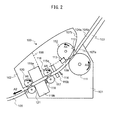
- FIG. 2 is a view for explaining an example of a conveyance route at an inside of a paper conveying apparatus 100.
- FIG. 3 is an example of a block diagram which shows a schematic configuration of a paper conveying apparatus 100.
- FIG. 4 is a flow chart which shows an example of operation of overall processing of a paper conveying apparatus 100.
- FIG. 5 is a flow chart which shows an example of an abnormality detection of the paper conveyance.
- FIG. 6 is a flow chart which shows an example of operation of sound jam detection processing.
- FIG. 7A is a graph which shows an example of a sound signal.
- FIG. 7B is a graph which shows an example of a signal of an absolute value of a sound signal.
- FIG. 7C is a graph which shows an example of a shape of a signal of an absolute value of a sound signal.
- FIG. 7D is a graph which shows an example of a counter value.
- FIG. 8A is a view for explaining processing for detection of an occurrence of a jam.
- FIG. 8B is a view for explaining processing for detection of an occurrence of a jam.
- FIG. 9 is a flow chart which shows an example of operations in special sound detection processing.
- FIG. 10 is a graph which shows an example of frequency signals.
- FIG. 11 is a graph which shows another example of frequency signals.
- FIG. 12 is a flow chart which shows an example of operation of position jam detection processing.
- FIG. 13 is a flow chart which shows an example of operation of multifeed detection processing.
- FIG. 14 a view for explaining properties of an ultrasonic signal.
- FIG. 15 is a flow chart which shows another example of operation of sound jam detection processing.
- FIG. 16 is a block diagram which shows the schematic configuration of a paper conveying apparatus 200 corresponding to another embodiment.
- FIG. 1 is an exemplary embodiment of a perspective view which shows a paper conveying apparatus 100 which is configured as an image scanner, according to an embodiment.
- the paper conveying apparatus 100 includes a lower housing 101, an upper housing 102, a paper tray 103, an ejection tray 105, an operation button 106, etc.
- the upper housing 102 is arranged at a position which covers the top surface of the paper conveying apparatus 100 and is engaged with the lower housing 101 by hinges so as to be able to be opened and closed at the time of a paper jam, at the time of cleaning of the inside of the paper conveying apparatus 100, etc.
- the paper tray 103 is engaged with the lower housing 101 in a manner enabling a paper to be placed.
- the paper tray 103 is provided with side guides 104a and 104b which can be moved in a direction perpendicular to a conveyance direction of the paper, that is, to the left and right directions from the conveyance direction of the paper. By positioning the side guides 104a and 104b to match with the width of the paper, it is possible to limit the width direction of the paper.
- the ejection tray 105 is engaged with the lower housing 101 by hinges so as to be able to pivot in the direction which is shown by an arrow mark A1. In the opened state as shown in FIG. 1 , the ejected paper can be held.
- the operation button 106 is arranged on the surface of the upper housing 102. If pushed, it generates and outputs an operation detection signal.
- FIG. 2 is a view for explaining an example of the conveyance route at the inside of the paper conveying apparatus 100.
- the conveyance route at the inside of the paper conveying apparatus 100 has a first paper detector 110, a paper feed roller 111, a retard roller 112, a microphone 113, a second paper detector 114, an ultrasonic transmitter 115a, an ultrasonic receiver 115b, a first conveyor roller 116, a first driven roller 117, a third paper detector 118, a first image capture unit 119a, a second image capture unit 119b, a second conveyor roller 120, a second driven roller 121, etc.
- the top surface of the lower housing 101 forms the lower guide 107a of the conveyance path of the paper, while the bottom surface of the upper housing 102 forms the upper guide 107b of the conveyance path of the paper.
- the arrow mark A2 shows the conveyance direction of the paper. Below, “upstream” means upstream of the conveyance direction A2 of the paper, while “downstream” means downstream of the conveyance direction A2 of the paper.
- the first paper detector 110 has a contact detection sensor which is arranged at an upstream side of the paper feed roller 111 and the retard roller 112 and detects if a paper is placed on the paper tray 103.
- the first paper detector 110 generates and outputs a first paper detection signal which changes in signal value between a state in which a paper is placed on the paper tray 103 and a state in which one is not placed.
- the microphone 113 is an example of a sound detector, is provided near a conveyance path of a paper, and detects the sound generated by a paper during conveyance of the paper, and generates and outputs an analog signal corresponding to the detected sound.
- the microphone 113 is arranged at the downstream side of the paper feed roller 111 and the retard roller 112 while fastened to the frame 108 at the inside of the upper housing 102.
- a hole 109 is provided in the upper guide 107b facing the microphone 113, so that the sound generated by the paper during conveyance of the paper can be more accurately detected by the microphone 113.
- the second paper detector 114 has a contact detection sensor which is arranged at a downstream side of the paper feed roller 111 and the retard roller 112 and at an upstream side of the first conveyor roller 116 and first driven roller 117 and detects if there is a paper present at that position.
- the second paper detector 114 generates and outputs a second paper detection signal which changes in signal value between a state at which there is a paper at that position and a state where there is no paper there.
- the ultrasonic transmitter 115a and the ultrasonic receiver 115b are an example of an ultrasonic detector, and are arranged near the conveyance path of the paper so as to face each other across the conveyance path.
- the ultrasonic transmitter 115a transmits an ultrasonic wave.
- the ultrasonic receiver 115b detects an ultrasonic wave which is transmitted by the ultrasonic transmitter 115a and passes through the paper or papers, and generates and outputs an ultrasonic signal comprised of an electrical signal corresponding to the detected ultrasonic wave.
- the ultrasonic transmitter 115a and the ultrasonic receiver 115b will sometimes be referred to altogether as the "ultrasonic sensor 115".
- the third paper detector 118 has a contact detection sensor which is arranged at a downstream side of the first conveyor roller 116 and the first driven roller 117 and an upstream side of the first image capture unit 119a and the second image capture unit 119b and detects if there is a paper at that position.
- the third paper detector 118 generates and outputs a third paper detection signal which changes in signal value between a state where there is a paper at that position and a state where there is no such paper there.
- the first image capture unit 119a has a CIS (contact image sensor) of an equal magnification optical system type which is provided with an image capture element using CMOS's (complementary metal oxide semiconductors) which are arranged in a line in the main scan direction.
- CMOS's complementary metal oxide semiconductors
- This CIS reads the back surface of the paper and generates and outputs an analog image signal.
- the second image capture unit 119b has a CIS of an equal magnification optical system type which is provided with an image capture element using CMOS's which are arranged in a line in the main scan direction. This CIS reads the front surface of the paper and generates and outputs an analog image signal.
- first image capture unit 119a and the second image capture unit 119b are also possible to arrange only one of the first image capture unit 119a and the second image capture unit 119b and read only one surface of the paper.
- image capture units 119 it is also possible to utilize an image capturing sensor of a reduced magnification optical system type using CCD's (charge coupled devices).
- CCD's charge coupled devices
- a paper which is placed on the paper tray 103 is conveyed between the lower guide 107a and the upper guide 107b toward the paper conveyance direction A2 by rotation of the paper feed roller 111 in the direction of the arrow mark A3 of FIG. 2 .
- the retard roller 112 rotates in the direction of the arrow mark A4 of FIG. 2 at the time of paper conveyance. Due to the action of the paper feed roller 111 and the retard roller 112, when the paper tray 103 has a plurality of papers placed on it, among the papers which are placed on the paper tray 103, only the paper which is in contact with the paper feed roller 111 is separated. The conveyance of papers other than the separated paper is restricted (prevention of multifeed).
- the paper feed roller 111 and the retard roller 112 function as a paper separator.
- a paper is fed between the first conveyor roller 116 and the first driven roller 117 while being guided by the lower guide 107a and the upper guide 107b.
- the paper is sent between the first image capture unit 119a and the second image capture unit 119b by the first conveyor roller 116 rotating in the direction of the arrow mark A5 of FIG. 2 .
- the paper which is read by the image capture unit 119 is ejected onto the ejection tray 105 by the second conveyor roller 120 rotating in the direction of the arrow mark A6 of the FIG. 2 .
- FIG. 3 is an example of a block diagram which shows the general configuration of a paper conveying apparatus 100.
- the paper conveying apparatus 100 in addition to the above-mentioned configuration, further has a first image A/D conversion unit 140a, a second image A/D conversion unit 140b, a sound signal generator 141, a drive unit 145, an interface 146, a storage unit 147, a central processing unit 150, etc.
- the first image A/D conversion unit 140a converts an analog image signal which is output from the first image capture unit 119a from an analog to digital format to generate digital image data which it then outputs to the central processing unit 150.
- the second image A/D conversion unit 140b converts the analog image signal which is output from the second image capture unit 119b from an analog to digital format to generate digital image data which it then outputs to the central processing unit 150.
- these digital image data will be referred to as the "read image”.
- the sound signal generator 141 includes a microphone 113, a filter 142, an amplifier 143, a sound A/D conversion unit 144, etc., and generates a sound signal.
- the filter 142 applies a bandpass filter which passes a predetermined frequency band of a signal to an analog signal which is output from the microphone 113 and outputs it to the amplifier 143.
- the amplifier 143 amplifies the signal which is output from the filter 142 and outputs it to the sound A/D conversion unit 144.
- the sound A/D conversion unit 144 converts the analog signal which is output from the amplifier 143 to a digital signal and outputs it to the central processing unit 150.
- a signal which is output by the sound signal generator 141 will be referred to as a "sound signal”.
- the sound signal generator 141 is not limited to this.
- the sound signal generator 141 may include only the microphone 113, while the filter 142, the amplifier 143, and the sound A/D conversion unit 144 may be provided outside of the sound signal generator 141. Further, the sound signal generator 141 may include only the microphone 113 and the filter 142 or only the microphone 113, the filter 142, and the amplifier 143.
- the drive unit 145 includes one or more motors and uses control signals from the central processing unit 150 to rotate the paper feed roller 111, the retard roller 112, the first conveyor roller 116, and the second conveyor roller 120 and operate to convey a paper.
- the interface 146 has, for example, a USB or other serial bus-based interface circuit and electrically connects with a not shown information processing apparatus (for example, personal computer, portable data terminal, etc.) to send and receive a read image and various types of information. Further, it is also possible to connect a flash memory etc., to the interface 146 so as to store the read image.
- a not shown information processing apparatus for example, personal computer, portable data terminal, etc.
- a flash memory etc. to the interface 146 so as to store the read image.
- the storage unit 147 has a RAM (random access memory), ROM (read only memory), or other memory device, a hard disk or other fixed disk device, or flexible disk, optical disk, or other portable storage device. Further, the storage unit 147 stores a computer program, database, tables, etc., which are used in various processing of the paper conveying apparatus 100.
- the computer program may be installed on the storage unit 147 from a computer-readable, non-transitory medium such as a compact disk read only memory (CD-ROM), a digital versatile disk read only memory (DVD-ROM), or the like by using a well-known setup program or the like. Furthermore, the storage unit 147 stores the read images.
- the central processing unit 150 is provided with a CPU (central processing unit) and operates based on a program which is stored in advance in the storage unit 147.
- the central processing unit 150 may also be comprised of a DSP (digital signal processor), LSI (large scale integrated circuit), ASIC (application specific integrated circuit), FPGA (field-programming gate array), etc.
- the central processing unit 150 is connected to the operation button 106, first paper detector 110, second paper detector 114, ultrasonic sensor 115, third paper detector 118, first image capture unit 119a, second image capture unit 119b, first image A/D conversion unit 140a, second image A/D conversion unit 140b, sound signal generator 141, drive unit 145, interface 146, and storage unit 147 and controls these units.
- the central processing unit 150 control a drive operation of the drive unit 145, control a paper read operation of the image capture unit 119, etc., to acquire a read image. Further, the central processing unit 150 has a control module 151, an image generator 152, a sound jam detector 153, a position jam detector 154, a multifeed detector 155, a special sound detector 156, a frequency signal generator 157, etc. These units are functional modules which are realized by software which operate on a processor. Note that, these units may be comprised of respectively independent integrated circuits, a microprocessor, firmware, etc.
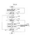
- FIG. 4 is a flow chart which shows an example of operation of overall processing of the paper conveying apparatus 100.
- the central processing unit 150 stands by until a user pushes the operation button 106 and an operation detection signal is received from the operation button 106 (step S101).
- the central processing unit 150 determines whether the paper tray 103 has a paper placed on it based on the first paper detection signal which was received from the first paper detector 110 (step S102).
- the central processing unit 150 returns the processing to step S101 and stands by until newly receiving an operation detection signal from the operation button 106.
- the central processing unit 150 drives the drive unit 145 to rotate the paper feed roller 111, retard roller 112, first conveyor roller 116, and second conveyor roller 121 and convey the paper (step S103).
- control module 151 determines whether an abnormality flag is ON or not (step S104).
- This abnormality flag is set OFF at the time of startup of the paper conveying apparatus 100 and is set ON if a later explained abnormality detection processing determines that an abnormality has occurred.
- the control module 151 When the abnormality flag is ON, the control module 151, as an abnormal processing, stops the drive unit 145 to stop the conveyance of the paper, uses a not shown speaker, LED (light emitting diode), etc. to notify the user of the occurrence of an abnormality, sets the abnormality flag OFF (step S105), and ends the series of steps.
- the image generator 152 makes the first image capture unit 119a and the second image capture unit 119b read the conveyed paper and acquires the read image through the first image A/D conversion unit 140a and the second image A/D conversion unit 140b (step S106).
- the central processing unit 150 transmits the acquired read image through the interface 146 to a not shown information processing apparatus (step S107). Note that, when not connected to an information processing apparatus, the central processing unit 150 stores the acquired read image in the storage unit 147.
- the central processing unit 150 determine whether the paper tray 103 has a paper remaining thereon based on the first paper detection signal which was received from the first paper detector 110 (step S108).
- the central processing unit 150 When the paper tray 103 has a paper remaining thereon, the central processing unit 150 returns the processing to step S103 and repeats the processing of steps S103 to S108. On the other hand, when the paper tray 103 does not have any paper remaining thereon, the central processing unit 150 ends the series of processing.
- FIG. 5 is a flow chart which shows an example of an abnormality detection of the paper conveyance of the paper conveying apparatus 100.
- the flow of operation which is explained below is executed based on a program which is stored in advance in the storage unit 147 mainly by the central processing unit 150 in cooperation with the elements of the paper conveying apparatus 100.
- the sound jam detector 153 executes sound jam detection processing (step S201).
- the sound jam detector 153 determines whether a jam has occurred based on the sound signal which was acquired from the sound signal generator 141.
- a jam which is determined to exist by the sound jam detector 153 based on a sound signal will be called a "sound jam”. Details of the sound jam detection processing will be explained later.
- the special sound detector 156 performs special sound detection processing (step S202).
- the special sound detector 156 determines whether a special sound has occurred based on a component of the sound signal which was acquired from the sound signal generator 141 in the special sound detection processing.
- the "special sound” means a sound with a specific frequency component much larger than the other frequency components. Details of the special sound detection processing will be explained later.
- the position jam detector 154 performs position jam detection processing (step S203).
- the position jam detector 154 determines the occurrence of a jam based on the second paper detection signal which is acquired from the second paper detector 114 and the third paper detection signal which is acquired from the third paper detector 118.
- a jam which is determined to exist by the position jam detector 154 based on the second paper detection signal and third paper detection signal will be called a "position jam”. Details of the position jam detection processing will be explained later.
- the multifeed detector 155 performs multifeed detection processing (step S204).
- the multifeed detector 155 determines the occurrence of a multifeed of papers based on the ultrasonic signal which was acquired from the ultrasonic sensor 116. Details of the multifeed detection processing will be explained later.
- the control module 151 determines whether an abnormality has occurred in the paper conveyance processing (step S205).
- the control module 151 determines that an abnormality has occurred if at least one of a sound jam, position jam, and paper multifeed has occurred. That is, it is determined that no abnormality has occurred when none of a sound jam, position jam, or paper multifeed has occurred.
- the control module 151 determines that a sound jam has occurred and determines that an abnormality has occurred when the sound jam detector 153 determines that a sound jam has occurred and the special sound detector 156 determines that a special sound has not been generated.
- the control module 151 determines that no sound jam has occurred and determines that no abnormality has occurred when the sound jam detector 153 determines that a sound jam has occurred and the special sound detector 156 determines that a special sound has been generated.
- the control module 151 sets the abnormality flag to ON (step S206) and ends the series of steps when an abnormality occurs in the paper conveyance processing. On the other hand, when no abnormality occurs in the paper conveyance processing, it ends the series of steps without particularly performing any further processing. Note that, the flow chart which is shown in FIG. 5 is repeatedly executed every predetermined time interval.
- FIG. 6 is a flow chart which shows an example of operation of a sound jam judgment processing.
- the sound jam detector 153 acquires a sound signal from the sound signal generator 141 (step S301).
- FIG. 7A is a graph which shows an example of a sound signal.
- the graph 700 which is shown in FIG. 7A shows a sound signal which is acquired from the sound signal generator 141.
- the abscissa of graph 700 shows the time, while the ordinate shows the signal value of the sound signal.
- the sound jam detector 153 generates a signal of the absolute value of the sound signal received from the sound signal generator 141 (step S302).
- FIG. 7B is a graph which shows an example of the signal of the absolute value of the sound signal.
- the graph 710 which is shown in FIG. 7B shows the signal of the absolute value of the sound signal of the graph 700.
- the abscissa of graph 710 shows the time, while the ordinate shows the signal of the absolute value of the sound signal.
- the sound jam detector 153 extracts a shape of a signal of the absolute value of the sound signal (step S303).
- the sound jam detector 153 extracts the envelope as the shape of the signal of the absolute value of the sound signal.
- FIG. 7C is a graph which shows an example of the shape of a signal of the absolute value of the sound signal.
- the graph 720 which is shown in FIG. 7C shows the envelope 721 of the signal of the absolute value of the sound signal of the graph 710.
- the abscissa of the graph 720 shows the time, while the ordinate shows the absolute value of the signal value of the sound signal.
- the sound jam detector 153 calculates a counter value which it increases when the shape of the signal of the absolute value of the sound signal is a first threshold value Th1 or more and which it decreases when it is less than the first threshold value Th1 (step S304).
- the sound jam detector 153 determines whether the value of the envelope 721 is the first threshold value Th1 or more at each predetermined time interval (for example, sampling intervals of sound signal), increments the counter value when the value of the envelope 721 is the first threshold value Th1 or more, and decrements the counter value when it is less than the first threshold value Th1.
- FIG. 7D is a graph which shows an example of the counter value which is calculated for the shape of the signal of the absolute value of the sound signal.
- the graph 730 which is shown in FIG. 7D expresses the counter value which is calculated for the envelope 721 of the graph 720.
- the abscissa of the graph 720 shows the time, while the ordinate shows the counter value.
- the sound jam detector 153 determines whether the counter value is a second threshold value Th2 or more (step S305). The sound jam detector 153 determines that a sound jam has occurred if the counter value is the second threshold value Th2 or more (step S306), determines that a sound jam has not occurred if the counter value is less than the second threshold value Th2 (step S307), and then ends the series of steps.
- the envelope 721 is the first threshold value Th1 or more at the time T1 and thereafter does not become less than the first threshold value Th1. For this reason, as shown in FIG. 7D , the counter value increases from the time T1 and becomes the second threshold value Th2 or more at the time T2, then the sound jam detector 153 determines that a sound jam has occurred.
- the sound jam detector 153 may acquire a signal of the peak hold for the signal of the absolute value of the sound signal (below, referred to as the "peak hold signal").
- the central processing unit 150 holds the local maximum value of the signal of the absolute value of the sound signal for exactly a predetermined hold period and then attenuates it by a constant attenuation rate to acquire the peak hold signal.
- FIG. 8A and FIG. 8B are views for explaining the processing for acquiring the peak hold signal from the sound signal and determining whether a sound jam has occurred.
- the graph 800 which is shown in FIG. 8A expresses the peak hold signal 801 for the signal of the absolute value of the sound signal of the graph 710.
- the abscissa of the graph 800 shows the time, while the ordinate shows the absolute value of the signal value of the sound signal.
- the graph 810 which is shown in FIG. 8B shows the counter value which was calculated for the peak hold signal 801 of the graph 800.
- the abscissa of the graph 810 shows the time, while the ordinate shows the counter value.
- the peak hold signal 801 becomes the first threshold value Th1 or more at the time T3, becomes less than the first threshold value Th1 at the time T4, again becomes the first threshold value Th1 or more at the time T5, and does not become less than the first threshold value Th1 after that.
- the counter value increases from the time T3, decreases from the time T4, again increases from the time T5, and becomes the second threshold value Th2 or more at the time T6, so it is determined that a sound jam has occurred.
- FIG. 9 is a flow chart which shows an example of the operations in special sound detection processing.
- the frequency signal generator 157 acquires a sound signal from the sound signal generator 141 (step S401).
- the frequency signal generator 157 generaets a frequency signal which is acquired by using a fast Fourier transform (FFT) to convert a sound signal which is received from the sound signal generator 141 to frequency (step S402).
- FFT fast Fourier transform
- the sound A/D conversion unit 144 samples the analog signal output by the amplifier 143 at 22 kHz to convert it to a digital format and generate a sound signal.
- the frequency signal generator 156 acquires 512 samples worth (94 msec worth) of the sound signal in 0 to 10000Hz in range at 43Hz intervals and converts them to frequency to generate a signal.
- the frequency signal generator 156 converts the signal acquired by converting the sound signal to frequency to decibels based on the maximum possible volume so as to generate the frequency signal.
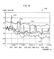
- FIG. 10 is a graph which shows an example of the frequency signals.
- the abscissa shows the frequency
- the ordinate shows the signal value of the frequency signal.
- the graph 1000 of FIG. 10 shows examples of a frequency signal 1001 at the time of normal paper feed, a frequency signal 1002 at the time of occurrence of a jam, a frequency signal 1003 at the time of generation of a squeaking sound at a specific device, and a frequency signal 1004 at the time of generation of a squeaking sound at other devices.
- the "squeaking sound” means the sound which is generated due to the stick-slip vibration which occurs due to the rubber members which are provided at the outer circumferential surfaces of the paper feed roller 111 and retard roller 112 contacting a paper.
- This stick-slip vibration causes the paper to vibrate, whereby the paper acts as a vibrating medium and the squeaking sound is amplified.
- the squeaking sound occurs inside the apparatus and has a magnitude equal to or greater than the sound which is generated due to a jam, so when a squeaking sound is generated, the sound jam detector 153 sometimes mistakenly determines that a jam has occurred.
- a specific frequency component (1400Hz) and its harmonic components (2800Hz, 4200Hz, 5600Hz, 7000Hz, 8400Hz, and 9600Hz) become much larger than the other frequency components.
- a specific frequency component (3400Hz) and its harmonic component (6800Hz) become much larger than the other frequency components.
- no tendency is seen for a specific frequency component to become much larger than the other frequency components to the extent of the frequency signal 1003 and the frequency signal 1004.
- the frequency components at all frequency bands become larger uniformly with respect to the frequency signal 1001 at the time of normal feed. No tendency is seen for specific frequency components to become much greater than the other frequency components like with the frequency signal 1003 and the frequency signal 1004.
- the special sound detector 156 calculates a sharpness of the frequency signal which is generated by the frequency signal generator 157 (step S403).
- the "sharpness” means the degree of magnitude by which a component of a specific frequency sticks out compared with the components of other frequencies.
- the special sound detector 156 calculates the sharpness for components of a predetermined frequency band which includes the above specific frequency and other frequencies in a frequency signal.
- the special sound detector 156 subtracts, for each frequency at 43Hz intervals, the average value of the frequency signal at nine points of frequency centered on that frequency from the value of the frequency signal at that frequency so as to calculate the difference.
- the special sound detector 156 calculates the maximum value of the differences which were calculated for respective frequencies of 0 to 10000Hz as the sharpness of the frequency signal.
- the special sound detector 156 determines if the calculated sharpness is a predetermined value or more (step S404).
- the predetermined value is set to a value, based on prior experiments, which enables the sharpness when a special sound has generated and the sharpness when a special sound has not generated to be differentiated. In the present example, it is made 15.
- the special sound detector 156 determines that the specific frequency component is much larger than the other frequency components and determines that a special sound has been generated (step S405), then the series of steps is ended.
- the special sound detector 156 determines that the specific frequency component is not much larger than the other frequency components and determines that no special sound has been generated (step S406), then the series of steps is ended.
- the sharpness of the frequency signal 1001 becomes 12 and the sharpness of the frequency signal 1002 becomes 3, so for the frequency signal 1001 and the frequency signal 1002, it is determined that no special sound has been generated.
- the sharpness of the frequency signal 1003 becomes 24 and the sharpness of the frequency signal 1004 becomes 18, so for the frequency signal 1003 and frequency signal 1004, it is determined that a special sound has been generated.
- the special sound detector 156 can also calculate the sharpness from the difference between the average value of the frequency signal of a frequency band which includes a plurality of frequencies and the average value of the frequency signal of a frequency band which includes that frequency band. In this case, the special sound detector 156 subtracts, for each frequency at 43Hz intervals, the average value of the frequency signal of the 387Hz frequency band which includes nine points of frequency centered on that frequency from the average value of the frequency signal of a 129Hz frequency band which includes three points of frequency centered on that frequency, so as to calculate the difference. The special sound detector 156 calculates the maximum value of the above difference which was calculated for each frequency from 0 to 10000Hz as the sharpness of the frequency signal.
- the special sound detector 156 can also calculate the sharpness from the difference between the average value of the frequency signal of a frequency band which includes a plurality of frequencies and the average value of the frequency signal of the total frequency band which generates the frequency signal. In this case, the special sound detector 156 subtracts, for each frequency at 43Hz intervals, the average value of the frequency signal of the 0 to 10000Hz frequency band from the average value of the frequency signal of a 129Hz frequency band which includes three points of frequency centered on that frequency so as to calculate the difference. The special sound detector 156 calculates the maximum value of the above difference which was calculated for each frequency from 0 to 10000Hz as the sharpness of the frequency signal.
- the special sound detector 156 can also calculate the sharpness from the sum of the absolute values of the differences between the values of the frequency components at the frequency signal and the values of the adjoining frequency components which respectively adjoin the frequencies.
- the special sound detector 156 calculates, for each frequency at 43Hz intervals, the absolute value of the difference between the value of the frequency signal at that frequency and the value of the frequency signal at a frequency adjoining that frequency (frequency 43Hz higher than that frequency).
- the special sound detector 156 calculates the sum of the above absolute values of the differences calculated for the frequencies from 0 to 10000Hz as the sharpness (see following formula (2)).
- the predetermined value can be made 450.
- the sharpness of the frequency signal 1001 becomes 421 and the sharpness of the frequency signal 1002 becomes 265, so for the frequency signal 1001 and frequency signal 1002, it is determined that no special sound has been generated.
- the sharpness of the frequency signal 1003 becomes 676 and the sharpness of the frequency signal 1004 becomes 510, so for the frequency signal 1003 and frequency signal 1004, it is determined that a special sound has been generated.
- the special sound detector 156 may calculate the sharpness from the difference between the average value of the frequency signal of a frequency band which includes a plurality of frequencies and the average value of the frequency signal of a frequency band which adjoins that frequency band.
- the special sound detector 156 divides the 0 to 10000Hz frequency band into 129Hz frequency bands each including three frequencies at 43Hz intervals.
- the special sound detector 156 calculates, for each divided frequency band, the absolute value of the difference between the average value of the frequency signal in that frequency band and the average value of the frequency signal in a frequency band which respectively adjoins that frequency band.
- the special sound detector 156 calculates the sum of the above absolute values of the differences which were calculated for the 0 to 10000Hz divided frequency bands as the sharpness.
- the special sound detector 156 may calculate the sharpness from the maximum value of the absolute values of the differences between values of the frequency components at the frequency signal and the values of the adjoining frequency components which respectively adjoin the frequency components.
- the special sound detector 156 calculates, for each frequency at 43Hz intervals, the absolute value of the difference between the value of the frequency signal at that frequency and the value of the frequency signal at a frequency which adjoins that frequency (frequency 43Hz higher than that frequency).
- the special sound detector 156 calculates the maximum value of the above absolute values of the differences calculated for the frequencies of 0 to 10000Hz as the sharpness (see following formula (3)). In this case, the predetermined value can be made 12.
- Sharpness max ⁇ P i - P ⁇ i - 1 2 ⁇ i ⁇ n
- the sharpness of the frequency signal 1001 becomes 10 and the sharpness of the frequency signal 1002 becomes 4, so for the frequency signal 1001 and frequency signal 1002, it is determined that no special sound has been generated.
- the sharpness of the frequency signal 1003 becomes 22 and the sharpness of the frequency signal 1004 becomes 14, so for the frequency signal 1003 and frequency signal 1004, it is determined that a special sound has been generated.
- the special sound detector 156 may calculate the sharpness from the difference between the average value of the frequency signal of a frequency band which includes a plurality of frequencies and the average value of the frequency signal of a frequency band which adjoins that frequency band.
- the special sound detector 156 divides the 0 to 10000Hz frequency band into 129Hz frequency bands each including three frequencies at 43Hz intervals.
- the special sound detector 156 calculates, for each divided frequency band, the absolute value of the difference between the average value of the frequency signal in that frequency band and the average value of frequency signal in a frequency band which respectively adjoins that frequency band.
- the special sound detector 156 calculates the maximum value of the absolute values of the differences which were calculated for the divided frequency bands from 0 to 10000Hz as the sharpness.
- the sampling frequency of the sound signal the range of frequency which generates a frequency signal, the interval of the sampled frequencies (resolution of frequency signal), and other values are not limited to the above-mentioned values and can be suitably changed.
- the range and number of frequencies in the case of calculating the average value of the frequency signal, the predetermined value for comparison with the sharpness, the number of frequencies in the divided frequency bands in the case of dividing the frequency bands, and other values are also not limited to the above-mentioned values and can be suitably changed.
- the frequency signal may also be made a signal which shows the absolute amount not converted to decibels.
- a squeaking sound has the property that a specific frequency component and its harmonic components become much larger than the other frequency components.
- the degree by which a component of a specific frequency sticks out from the components of other frequencies in a frequency signal becomes larger when a squeaking sound is generated than when a squeaking sound is not generated. Therefore, as explained above, it is possible to precisely determine whether a squeaking sound has been generated by utilizing the sharpness of the frequency signal.
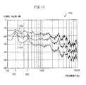
- FIG. 11 is a graph which shows another example of the frequency signals.
- the abscissa shows a frequency by a log, while the ordinate shows a signal value of the frequency signal.
- the graph 1100 of FIG. 11 shows examples of a frequency signal 1101 when a normal paper which does not have wrinkles (below, referred to as "normal paper") is conveyed, a frequency signal 1102 when a paper which has wrinkles (below, referred to as "wrinkled paper”) is conveyed, and a frequency signal 1103 when a jam occurs.
- the frequency signal 1102 is larger than the frequency signal 1101 over the entire frequency band.
- the sound jam detector 153 sometimes mistakenly determines that a jam has occurred.
- the special sound detector 156 can detect the rubbing sound when separating papers (wrinkled paper and normal paper) as a special sound.
- FIG. 12 is a flow chart which shows an example of operation of a position jam detection processing.
- the position jam detector 154 stands by until the front end of the paper is detected by the second paper detector 114 (step S501).
- the position jam detector 154 determines that the front end of the paper is detected at the position of the second paper detector 114, that is, downstream of the paper feed roller 111 and retard roller 112 and upstream of the first conveyor roller 116 and first driven roller 117, when the value of the second paper detection signal from the second paper detector 114 changes from a value which shows the state where there is no paper to a value which shows the state where there is one.
- step S502 when the second paper detector 114 detects the front end of a paper, the position jam detector 154 starts counting time (step S502).
- the position jam detector 154 determines whether the third paper detector 118 has detected the front end of the paper (step S503).
- the position jam detector 154 determines that the front end of the paper is detected at the position of the third paper detector 118, that is, downstream of the first conveyor roller 116 and first driven roller 117 and upstream of the image capture unit 119, when the value of the third paper detection signal from the third paper detector 118 changes from a value which shows the state where there is no paper to a value which shows the state where there is one.
- the position jam detector 154 determines that no position jam has occurred (step S504) and ends the series of steps.
- the position jam detector 154 determines whether a predetermined time (for example, 1 second) has elapsed from the start of counting time (step S505). If a predetermined time has not elapsed, the position jam detector 154 returns to the processing of step S503 and again determines whether the third paper detector 118 has detected the front end of the paper. On the other hand, when a predetermined time has elapsed, the position jam detector 154 determines that position jam has occurred (step S506) and ends the series of steps. Note that, when position jam detection processing is not required in the paper conveying apparatus 100, this may be omitted.
- a predetermined time for example, 1 second
- the central processing unit 150 when the central processing unit 150 detects that the front end of a paper is downstream of the first conveyor roller 116 and the first driven roller 117 by the third paper detection signal from the third paper detector 118, it controls the drive unit 145 to stop the rotation of the paper feed roller 111 and retard roller 112 so that the next paper is not fed. After that, when the central processing unit 150 detects the rear end of the paper downstream of the paper feed roller 111 and the retard roller 112 by the second paper detection signal from the second paper detector 114, it again controls the drive unit 145 to rotate the paper feed roller 111 and retard roller 112 and convey the next paper. Due to this, the central processing unit 150 prevents a plurality of papers from being superposed in the conveyance path.
- the position jam detector 154 may start counting the time at the point of time when the central processing unit 150 controls the drive unit 145 to rotate the paper feed roller 111 and the retard roller 112 and determine that a position jam has occurred when the third paper detector 118 does not detect the front end of a paper within a predetermined time.
- FIG. 13 is a flow chart which shows an example of operation of multifeed detection processing.
- the multifeed detector 155 acquires an ultrasonic signal from the ultrasonic sensor 115 (step S601).
- the multifeed detector 155 determines whether the signal value of the acquired ultrasonic signal is less than the multifeed detection threshold value (step S602).
- FIG. 14 is a view for explaining properties of an ultrasonic signal.
- the solid line 1401 shows the characteristic of the ultrasonic signal in the case where a single paper is conveyed
- the broken line 1402 shows the characteristic of the ultrasonic signal in the case where multifeed of papers has occurred.
- the abscissa of the graph 1400 shows the time, while the ordinate shows the signal value of the ultrasonic signal. Due to the occurrence of multifeed, the signal value of the ultrasonic signal of the broken line 1402 falls in the section 1403. For this reason, it is possible to determine whether multifeed of papers has occurred by whether the signal value of the ultrasonic signal is less than the multifeed detection threshold value ThA.
- the solid line 1404 shows the characteristic of the ultrasonic signal in the case where just one plastic card thicker than paper is conveyed.
- the signal value of the ultrasonic signal becomes smaller than the multifeed detection threshold value ThA, so the multifeed detector 155 mistakenly determines that a multifeed of papers has occurred. Note that, even if sufficiently thick, high rigidity thick paper has been conveyed, an ultrasonic signal which has characteristics similar to the case where a plastic card is conveyed is detected, so the multifeed detector 155 is liable to mistakenly determine that a multifeed of papers has occurred.
- the multifeed detector 155 determines that multifeed of the papers has occurred when the signal value of the ultrasonic signal is less than the multifeed detection threshold value (step S603), determines that multifeed of the papers has not occurred when the signal value of the ultrasonic signal is the multifeed detection threshold value or more (step S604), and ends the series of steps.
- the paper conveying apparatus 100 operates in accordance with the flow charts of FIG. 4 , FIG. 5 , FIG. 6 , and FIG. 9 to thereby determine any occurrence of a jam and any generation of a special sound due to a cause other than a jam based on the sound generated by a paper during conveyance.
- the paper conveying apparatus 100 deems that no jam has occurred even when it is determined that a jam has occurred if that sound is a special sound, so it becomes possible to suppress mistaken detection of the occurrence of a jam.
- the paper conveying apparatus 100 detects a special sound based on the sharpness of a frequency signal, so can accurately detect a squeaking sound and rubbing sound at the time of paper separation as special sounds.
- FIG. 15 is a flow chart which shows another example of the operations in the sound jam detection processing.
- This flow chart can be used at the paper conveying apparatus 100 instead of the above-mentioned flow chart which is shown in FIG. 6 .
- the sound jam detector 153 determines whether a jam has occurred based on a frequency component other than a frequency component which becomes larger when a special sound is generated, in the sound signal.
- the processing of steps S705 to S709 which are shown in FIG. 15 is the same as the processing of steps S303 to S307 which are shown in FIG. 6 , so the explanation will be omitted and, below, only the processing of steps S701 to S704 will be explained. Note that, when the flow chart which is shown in FIG. 15 is used instead of the flow chart which is shown in FIG. 6 , in the abnormality detection processing which is shown in FIG. 5 , the special sound detection processing of step S202 is performed before the sound jam detection processing of step S201.
- the sound jam detector 153 acquires the frequency signal from the frequency signal generator 157 (step S701).
- the sound jam detector 153 extracts the frequency signal of the frequency band for sound jam detection from the frequency signal which was acquired from the frequency signal generator 157 (step S702).
- the sound jam detector 153 extracts a frequency band other than the frequency band for special sound detection as the frequency band for sound jam detection. Note that, a frequency band which includes nine points of frequency where the difference which was calculated at step S403 of FIG. 9 becomes the predetermined value or more which was used at step S404 becomes the frequency band for special sound detection. At the frequency band for sound jam detection, there is little influence by a squeaking sound, rubbing sound at the time of separation of a paper, and other special sounds, so the sound jam detector 153 can improve the precision of detection by determining any occurrence of a sound jam based on a frequency component of the frequency band for sound jam detection.
- the sound jam detector 153 generate an inverse frequency-converted signal by converting the extracted frequency signal of the frequency band for sound jam detection using an inverse fast Fourier transform (step S703).
- the sound jam detector 153 generates a signal which acquires the absolute value of the inverse frequency converted signal (step S704). After that, at steps S705 to S709, the sound jam detector 153 uses a signal which acquires the absolute value of the inverse frequency converted signal instead of a signal which acquires the absolute value of the sound signal so as to perform the sound jam detection processing.
- the sound jam detector 153 may also not convert the frequency signal which was extracted at step S702 to the inverse frequency, but determine whether a sound jam has occurred directly from the extracted frequency signal. In that case, the sound jam detector 153 determines that a sound jam has occurred when the average value of signal values at the different frequencies of the extracted frequency signal becomes a predetermined value or more continuously for a predetermined time or more.
- the frequency band where the frequency component becomes higher when a squeaking sound is generated is determined by the material, size, structure, etc., of the rubber members which are provided at the outer circumferential surfaces of the paper feed roller 111 and retard roller 112. Therefore, it is also possible run experiments in advance to investigate the frequency band at which a frequency component becomes larger when a squeaking sound is generated, set that frequency band as the frequency band for special sound detection, and set a frequency band other than the frequency band for special sound detection as the frequency band for sound jam detection.
- the frequency band where the frequency component becomes higher when a rubbing sound is generated at the time of separation of a paper is determined by the material, size, structure, etc., of the rubber members which are provided at the outer circumferential surfaces of the paper feed roller 111 and retard roller 112. Therefore, it is also possible run experiments in advance to investigate the frequency band at which a frequency component becomes larger when a paper is conveyed, set that frequency band as the frequency band for special sound detection, and set a frequency band other than the frequency band for special sound detection as the frequency band for sound jam detection.
- the paper conveying apparatus 100 operates in accordance with the flow charts which are shown in FIG. 4 , FIG. 5 , FIG. 9 , and FIG. 15 so as to determine whether a sound jam has occurred based on the frequency component of a frequency band which is little influenced by a special sound. Therefore, the paper conveying apparatus 100 can improve the precision of detection of a sound jam.
- FIG. 16 is a block diagram which shows the schematic configuration of a paper conveying apparatus 200 according to another embodiment.
- the paper conveying apparatus 200 which is shown in FIG. 16 has a sound signal generator 241 instead of the sound signal generator 141 of the paper conveying apparatus 100 which is shown in FIG. 3 . Further, the central processing unit 250 does not have the frequency signal generator 157.
- the sound signal generator 241 includes a microphone 113, a first filter 242a, a second filter 242b, a first amplifier 243a, a second amplifier 243b, a first sound A/D conversion unit 244a, a second sound A/D conversion unit 244b, etc.
- the first filter 242a processes the analog signal which was output from the microphone 113 by applying a bandpass filter which passes a signal of a predetermined frequency band for sound jam detection and outputs it to the first amplifier 243a.
- the first amplifier 243a amplifies the signal which was output from the first filter 242a and outputs it to the first sound A/D conversion unit 244a.
- the first sound A/D conversion unit 244a converts the analog signal which was output from the first amplifier 243a to a digital signal and outputs it to the central processing unit 250.
- the signal which is output by the first sound A/D conversion unit 244a will be called the "sound signal for sound jam detection".
- the second filter 242b processes the analog signal which is output from the microphone 113 by applying a bandpass filter which passes a signal of a predetermined frequency band for special sound detection and outputs it to the second amplifier 243b.
- the second amplifier 243b amplifies the signal which is output from the second filter 242b and outputs it to the second sound A/D conversion unit 244b.
- the second sound A/D conversion unit 244b converts the analog signal which was output from the second amplifier 243b to a digital signal and outputs it to the central processing unit 250.
- the signal which is output by the second sound A/D conversion unit 244b will be called the "sound signal for special sound detection".
- the sound jam detector 153 determines whether a sound jam has occurred based on the sound signal for sound jam detection.
- the special sound detector 156 determines whether a special sound has been generated based on the sound signal for special sound detection. The special sound detector 156 determines that a special sound has been generated when the signal value of the sound signal for special sound detection becomes a predetermined value or more continuously for a predetermined time.
- the microphone for detecting sound for sound jam detection and the microphone for detecting sound for special sound detection may be separately provided.
- the microphone for sound jam detection is arranged near a side wall of the paper conveyance path which the paper contacts and where a jam easily occurs
- the microphone for special sound detection is arranged near the paper feed roller 111 and retard roller 112 where a squeaking sound and rubbing sound of wrinkled paper generate.
- the microphone for sound jam detection also detects some of the squeaking sound and rubbing sound of wrinkled paper, but the ratio of the squeaking sound and rubbing sound of wrinkled paper to the sound which is generated due to a jam becomes small. Therefore, in the sound signal for sound jam detection, by setting a threshold value between the magnitude of the sound which is generated due to a jam and the magnitude of the squeaking sound and rubbing sound of wrinkled paper and cutting the components of that threshold value or less, it is possible to eliminate the effects of the squeaking sound and rubbing sound of wrinkled paper.
- the microphone for special sound detection detects some of the sound which is generated due to a jam, but the ratio of the sound which is generated due to a jam to the squeaking sound and rubbing sound of wrinkled paper becomes small. Therefore, in the sound signal for special sound detection, by setting a threshold value between the magnitude of the squeaking sound and rubbing sound of wrinkled paper and the magnitude of sound which is generated due to a jam and cutting the components of that threshold value or less, it is possible to eliminate the effects of a sound which is generated due to a jam.
- the paper conveying apparatus 200 determines whether a special sound has been generated based on the sound signal which is processed by using a filter for special sound detection and determines whether a sound jam has occurred based on the sound signal which is processed by using a filter for sound jam detection. Therefore, the paper conveying apparatus 200 can more precisely detect a special sound and can more precisely detect a sound jam when the frequency band at which the frequency component becomes higher when a special sound is generated is known in advance.
- the microphone for detecting a sound for sound jam detection and the microphone for detecting a sound for special sound detection are arranged separately at positions enabling good detection of the respective sounds. Therefore, the paper conveying apparatus 200 can precisely detect a special sound and can more precisely detect a sound jam.
Landscapes
- Physics & Mathematics (AREA)
- General Physics & Mathematics (AREA)
- Engineering & Computer Science (AREA)
- Mechanical Engineering (AREA)
- Controlling Sheets Or Webs (AREA)
- Facsimiles In General (AREA)
Applications Claiming Priority (1)
| Application Number | Priority Date | Filing Date | Title |
|---|---|---|---|
| JP2012203557A JP5409868B1 (ja) | 2012-09-14 | 2012-09-14 | 原稿搬送装置、ジャム判定方法及びコンピュータプログラム |
Publications (3)
| Publication Number | Publication Date |
|---|---|
| EP2708952A2 true EP2708952A2 (de) | 2014-03-19 |
| EP2708952A3 EP2708952A3 (de) | 2016-07-20 |
| EP2708952B1 EP2708952B1 (de) | 2020-03-25 |
Family
ID=49000843
Family Applications (1)
| Application Number | Title | Priority Date | Filing Date |
|---|---|---|---|
| EP13180973.3A Active EP2708952B1 (de) | 2012-09-14 | 2013-08-20 | Papierfördervorrichtung, Stauerkennungsverfahren, und Computerprogramm |
Country Status (4)
| Country | Link |
|---|---|
| US (1) | US8783684B2 (de) |
| EP (1) | EP2708952B1 (de) |
| JP (1) | JP5409868B1 (de) |
| CN (1) | CN103662898B (de) |
Cited By (1)
| Publication number | Priority date | Publication date | Assignee | Title |
|---|---|---|---|---|
| EP2799377A1 (de) * | 2013-05-02 | 2014-11-05 | Pfu Limited | Papierfördervorrichtung |
Families Citing this family (6)
| Publication number | Priority date | Publication date | Assignee | Title |
|---|---|---|---|---|
| JP2013234033A (ja) * | 2012-05-08 | 2013-11-21 | Canon Inc | 画像形成装置およびシート材の再搬送可否判別方法 |
| US9592980B2 (en) | 2013-12-13 | 2017-03-14 | Pfu Limited | Paper conveying apparatus, jam detection method, and computer-readable, non-transitory medium |
| US9712686B1 (en) * | 2016-03-30 | 2017-07-18 | Kyocera Document Solutions Inc. | Printer diagnostics using external microphone |
| JP6239060B1 (ja) * | 2016-07-29 | 2017-11-29 | 株式会社Pfu | 原稿搬送装置、制御方法及び制御プログラム |
| US11385587B2 (en) * | 2020-04-02 | 2022-07-12 | Canon Kabushiki Kaisha | Image forming apparatus |
| WO2022004224A1 (ja) * | 2020-06-30 | 2022-01-06 | パナソニック インテレクチュアル プロパティ コーポレーション オブ アメリカ | 紙詰まり予兆検知装置、紙詰まり予兆検知方法、及び、プログラム |
Citations (1)
| Publication number | Priority date | Publication date | Assignee | Title |
|---|---|---|---|---|
| JP2001302021A (ja) | 2000-04-25 | 2001-10-31 | Canon Inc | 紙ジャム検知装置、紙ジャム検知方法、画像記録装置 |
Family Cites Families (39)
| Publication number | Priority date | Publication date | Assignee | Title |
|---|---|---|---|---|
| US4022460A (en) | 1976-02-05 | 1977-05-10 | Pitney-Bowes, Inc. | Document jam detector for copier |
| JPS57169767A (en) | 1981-04-14 | 1982-10-19 | Fuji Xerox Co Ltd | Jam detecting device for copying machine |
| JPS60112547A (ja) | 1983-11-18 | 1985-06-19 | Hitachi Ltd | 紙幣搬送異常検知装置 |
| JPS61169983A (ja) | 1985-01-23 | 1986-07-31 | 株式会社東芝 | 印刷物の判別装置 |
| JPH10267742A (ja) * | 1997-03-24 | 1998-10-09 | Fuji Xerox Co Ltd | 音質評価装置および音質評価方法 |
| JPH1153602A (ja) | 1997-08-08 | 1999-02-26 | Glory Ltd | 紙葉類の正損検出方法及び装置 |
| WO2002037067A1 (en) * | 2000-11-06 | 2002-05-10 | Nsk Ltd. | Abnormality diagnosing device and method for mechanical equipment |
| JP2006322947A (ja) * | 2000-12-06 | 2006-11-30 | Nsk Ltd | 機械設備の振動ピーク値抽出方法およびピーク値抽出装置 |
| JP2002205449A (ja) | 2001-01-10 | 2002-07-23 | Ricoh Co Ltd | 印刷処理システム |
| JP2003176063A (ja) | 2001-06-15 | 2003-06-24 | Omron Corp | 紙葉類重送検出装置および方法、並びにプログラム |
| JP2003295707A (ja) | 2002-04-03 | 2003-10-15 | Konica Corp | 画像形成装置 |
| JP4451723B2 (ja) | 2004-06-08 | 2010-04-14 | ニスカ株式会社 | シート取扱い装置 |
| MXPA06015102A (es) | 2004-07-01 | 2007-02-08 | Diebold Inc | Metodo y aparato detector de hojas multiples de maquina bancaria automatizada. |
| JP2006193287A (ja) * | 2005-01-14 | 2006-07-27 | Pfu Ltd | シート給送装置及び該装置のジャム検出方法 |
| JP2007079263A (ja) | 2005-09-15 | 2007-03-29 | Canon Inc | 画像形成装置、画像形成システム、及び画像形成装置の制御方法 |
| JP5072439B2 (ja) * | 2006-06-08 | 2012-11-14 | キヤノン株式会社 | 画像形成装置 |
| JP4929049B2 (ja) | 2007-05-23 | 2012-05-09 | 株式会社リコー | 画像処理装置 |
| US20090022536A1 (en) | 2007-07-18 | 2009-01-22 | Hewlett-Packard Development Company Lp | Sound based media drive |
| JP2009161292A (ja) | 2007-12-28 | 2009-07-23 | Murata Mach Ltd | 画像読取装置 |
| JP5113620B2 (ja) | 2008-01-30 | 2013-01-09 | 株式会社リコー | 画像形成装置 |
| JP2009249046A (ja) | 2008-04-01 | 2009-10-29 | Ricoh Elemex Corp | 用紙搬送装置、用紙搬送異常検知方法 |
| US8160467B2 (en) | 2009-04-28 | 2012-04-17 | Xerox Corporation | Apparatus and method for print apparatus rotational assembly cleaning blade adjustment |
| JP5407800B2 (ja) | 2009-11-24 | 2014-02-05 | 株式会社リコー | 画像形成装置 |
| US20110238423A1 (en) | 2010-03-29 | 2011-09-29 | Schaertel David M | Sonic document classification |
| JP5409591B2 (ja) | 2010-12-20 | 2014-02-05 | 京セラドキュメントソリューションズ株式会社 | 画像形成装置 |
| JP5623317B2 (ja) | 2011-03-18 | 2014-11-12 | 株式会社Pfu | 給紙装置、画像読取装置、給紙方法、及びプログラム |
| US9217980B2 (en) | 2011-10-14 | 2015-12-22 | Kodak Alaris Inc. | Jam sensing at document feeding station |
| US8567777B2 (en) * | 2011-12-06 | 2013-10-29 | Eastman Kodak Company | Combined ultrasonic-based multifeed detection method and sound-based damage detection method |
| US8585050B2 (en) | 2011-12-06 | 2013-11-19 | Eastman Kodak Company | Combined ultrasonic-based multifeed detection system and sound-based damage detection system |
| US20130140757A1 (en) | 2011-12-06 | 2013-06-06 | Daniel P. Phinney | Sound-based damage detection |
| JP5404873B1 (ja) | 2012-08-24 | 2014-02-05 | 株式会社Pfu | 原稿搬送装置、ジャム判定方法及びコンピュータプログラム |
| JP5404870B1 (ja) * | 2012-08-24 | 2014-02-05 | 株式会社Pfu | 用紙読取装置、ジャム判定方法及びコンピュータプログラム |
| JP5404876B1 (ja) * | 2012-08-24 | 2014-02-05 | 株式会社Pfu | 用紙搬送装置、ジャム判定方法及びコンピュータプログラム |
| JP5404872B1 (ja) * | 2012-08-24 | 2014-02-05 | 株式会社Pfu | 用紙搬送装置、重送判定方法及びコンピュータプログラム |
| JP5791575B2 (ja) | 2012-08-28 | 2015-10-07 | 京セラドキュメントソリューションズ株式会社 | 用紙搬送装置、画像形成装置 |
| JP5409860B1 (ja) | 2012-09-05 | 2014-02-05 | 株式会社Pfu | 原稿搬送装置、復旧方法及びコンピュータプログラム |
| JP5409859B1 (ja) | 2012-09-05 | 2014-02-05 | 株式会社Pfu | 原稿搬送装置、復旧方法及びコンピュータプログラム |
| JP5404881B1 (ja) * | 2012-09-14 | 2014-02-05 | 株式会社Pfu | 原稿搬送装置、ジャム判定方法及びコンピュータプログラム |
| JP5404880B1 (ja) * | 2012-09-14 | 2014-02-05 | 株式会社Pfu | 用紙搬送装置、異常判定方法及びコンピュータプログラム |
-
2012
- 2012-09-14 JP JP2012203557A patent/JP5409868B1/ja active Active
-
2013
- 2013-08-14 US US13/966,778 patent/US8783684B2/en active Active
- 2013-08-20 EP EP13180973.3A patent/EP2708952B1/de active Active
- 2013-08-22 CN CN201310370376.7A patent/CN103662898B/zh not_active Expired - Fee Related
Patent Citations (1)
| Publication number | Priority date | Publication date | Assignee | Title |
|---|---|---|---|---|
| JP2001302021A (ja) | 2000-04-25 | 2001-10-31 | Canon Inc | 紙ジャム検知装置、紙ジャム検知方法、画像記録装置 |
Cited By (2)
| Publication number | Priority date | Publication date | Assignee | Title |
|---|---|---|---|---|
| EP2799377A1 (de) * | 2013-05-02 | 2014-11-05 | Pfu Limited | Papierfördervorrichtung |
| US8934115B2 (en) | 2013-05-02 | 2015-01-13 | Pfu Limited | Paper conveying apparatus |
Also Published As
| Publication number | Publication date |
|---|---|
| US20140077447A1 (en) | 2014-03-20 |
| US8783684B2 (en) | 2014-07-22 |
| JP5409868B1 (ja) | 2014-02-05 |
| CN103662898B (zh) | 2016-10-05 |
| EP2708952A3 (de) | 2016-07-20 |
| JP2014058363A (ja) | 2014-04-03 |
| EP2708952B1 (de) | 2020-03-25 |
| CN103662898A (zh) | 2014-03-26 |
Similar Documents
| Publication | Publication Date | Title |
|---|---|---|
| US8840108B2 (en) | Paper reading apparatus, jam detection method, and computer-readable, non-transitory medium | |
| US8764010B2 (en) | Paper conveying apparatus, multifeed detection method, and computer-readable, non-transitory medium | |
| EP2799377B1 (de) | Papierfördervorrichtung | |
| EP2708952B1 (de) | Papierfördervorrichtung, Stauerkennungsverfahren, und Computerprogramm | |
| US8991820B2 (en) | Paper conveying apparatus, jam detection method, and computer-readable, non-transitory medium | |
| US9039010B2 (en) | Paper conveying apparatus, jam detection method, and computer-readable, non-transitory medium | |
| CN103625953B (zh) | 纸张输送装置以及卡纸判定方法 | |
| US8925921B2 (en) | Paper conveying apparatus, abnormality detection method, and computer-readable, non-transitory medium | |
| US8925920B2 (en) | Paper conveying apparatus, abnormality detection method, and computer-readable, non-transitory medium | |
| US8820741B2 (en) | Paper conveying apparatus, jam detection method, and computer-readable, non-transitory medium | |
| US8827266B2 (en) | Paper conveying apparatus, jam detection method, and computer-readable, non-transitory medium | |
| US8807561B2 (en) | Paper conveying apparatus, jam detection method, and computer-readable, non-transitory medium | |
| US8864130B2 (en) | Image reading apparatus with sound detector and sound signal generator | |
| US8870181B2 (en) | Paper conveying apparatus with side guide and sound detector |
Legal Events
| Date | Code | Title | Description |
|---|---|---|---|
| PUAI | Public reference made under article 153(3) epc to a published international application that has entered the european phase |
Free format text: ORIGINAL CODE: 0009012 |
|
| AK | Designated contracting states |
Kind code of ref document: A2 Designated state(s): AL AT BE BG CH CY CZ DE DK EE ES FI FR GB GR HR HU IE IS IT LI LT LU LV MC MK MT NL NO PL PT RO RS SE SI SK SM TR |
|
| AX | Request for extension of the european patent |
Extension state: BA ME |
|
| PUAL | Search report despatched |
Free format text: ORIGINAL CODE: 0009013 |
|
| AK | Designated contracting states |
Kind code of ref document: A3 Designated state(s): AL AT BE BG CH CY CZ DE DK EE ES FI FR GB GR HR HU IE IS IT LI LT LU LV MC MK MT NL NO PL PT RO RS SE SI SK SM TR |
|
| AX | Request for extension of the european patent |
Extension state: BA ME |
|
| RIC1 | Information provided on ipc code assigned before grant |
Ipc: B65H 5/00 20060101ALI20160615BHEP Ipc: G03G 15/00 20060101AFI20160615BHEP |
|
| STAA | Information on the status of an ep patent application or granted ep patent |
Free format text: STATUS: REQUEST FOR EXAMINATION WAS MADE |
|
| 17P | Request for examination filed |
Effective date: 20170119 |
|
| RBV | Designated contracting states (corrected) |
Designated state(s): AL AT BE BG CH CY CZ DE DK EE ES FI FR GB GR HR HU IE IS IT LI LT LU LV MC MK MT NL NO PL PT RO RS SE SI SK SM TR |
|
| GRAP | Despatch of communication of intention to grant a patent |
Free format text: ORIGINAL CODE: EPIDOSNIGR1 |
|
| STAA | Information on the status of an ep patent application or granted ep patent |
Free format text: STATUS: GRANT OF PATENT IS INTENDED |
|
| INTG | Intention to grant announced |
Effective date: 20191016 |
|
| GRAS | Grant fee paid |
Free format text: ORIGINAL CODE: EPIDOSNIGR3 |
|
| GRAA | (expected) grant |
Free format text: ORIGINAL CODE: 0009210 |
|
| STAA | Information on the status of an ep patent application or granted ep patent |
Free format text: STATUS: THE PATENT HAS BEEN GRANTED |
|
| AK | Designated contracting states |
Kind code of ref document: B1 Designated state(s): AL AT BE BG CH CY CZ DE DK EE ES FI FR GB GR HR HU IE IS IT LI LT LU LV MC MK MT NL NO PL PT RO RS SE SI SK SM TR |
|
| REG | Reference to a national code |
Ref country code: GB Ref legal event code: FG4D |
|
| REG | Reference to a national code |
Ref country code: DE Ref legal event code: R096 Ref document number: 602013067103 Country of ref document: DE |
|
| REG | Reference to a national code |
Ref country code: AT Ref legal event code: REF Ref document number: 1249237 Country of ref document: AT Kind code of ref document: T Effective date: 20200415 Ref country code: IE Ref legal event code: FG4D |
|
| PG25 | Lapsed in a contracting state [announced via postgrant information from national office to epo] |
Ref country code: NO Free format text: LAPSE BECAUSE OF FAILURE TO SUBMIT A TRANSLATION OF THE DESCRIPTION OR TO PAY THE FEE WITHIN THE PRESCRIBED TIME-LIMIT Effective date: 20200625 Ref country code: FI Free format text: LAPSE BECAUSE OF FAILURE TO SUBMIT A TRANSLATION OF THE DESCRIPTION OR TO PAY THE FEE WITHIN THE PRESCRIBED TIME-LIMIT Effective date: 20200325 Ref country code: RS Free format text: LAPSE BECAUSE OF FAILURE TO SUBMIT A TRANSLATION OF THE DESCRIPTION OR TO PAY THE FEE WITHIN THE PRESCRIBED TIME-LIMIT Effective date: 20200325 |
|
| PG25 | Lapsed in a contracting state [announced via postgrant information from national office to epo] |
Ref country code: GR Free format text: LAPSE BECAUSE OF FAILURE TO SUBMIT A TRANSLATION OF THE DESCRIPTION OR TO PAY THE FEE WITHIN THE PRESCRIBED TIME-LIMIT Effective date: 20200626 Ref country code: HR Free format text: LAPSE BECAUSE OF FAILURE TO SUBMIT A TRANSLATION OF THE DESCRIPTION OR TO PAY THE FEE WITHIN THE PRESCRIBED TIME-LIMIT Effective date: 20200325 Ref country code: LV Free format text: LAPSE BECAUSE OF FAILURE TO SUBMIT A TRANSLATION OF THE DESCRIPTION OR TO PAY THE FEE WITHIN THE PRESCRIBED TIME-LIMIT Effective date: 20200325 Ref country code: SE Free format text: LAPSE BECAUSE OF FAILURE TO SUBMIT A TRANSLATION OF THE DESCRIPTION OR TO PAY THE FEE WITHIN THE PRESCRIBED TIME-LIMIT Effective date: 20200325 Ref country code: BG Free format text: LAPSE BECAUSE OF FAILURE TO SUBMIT A TRANSLATION OF THE DESCRIPTION OR TO PAY THE FEE WITHIN THE PRESCRIBED TIME-LIMIT Effective date: 20200625 |
|
| REG | Reference to a national code |
Ref country code: NL Ref legal event code: MP Effective date: 20200325 |
|
| REG | Reference to a national code |
Ref country code: LT Ref legal event code: MG4D |
|
| PG25 | Lapsed in a contracting state [announced via postgrant information from national office to epo] |
Ref country code: NL Free format text: LAPSE BECAUSE OF FAILURE TO SUBMIT A TRANSLATION OF THE DESCRIPTION OR TO PAY THE FEE WITHIN THE PRESCRIBED TIME-LIMIT Effective date: 20200325 |
|
| PG25 | Lapsed in a contracting state [announced via postgrant information from national office to epo] |
Ref country code: PT Free format text: LAPSE BECAUSE OF FAILURE TO SUBMIT A TRANSLATION OF THE DESCRIPTION OR TO PAY THE FEE WITHIN THE PRESCRIBED TIME-LIMIT Effective date: 20200818 Ref country code: LT Free format text: LAPSE BECAUSE OF FAILURE TO SUBMIT A TRANSLATION OF THE DESCRIPTION OR TO PAY THE FEE WITHIN THE PRESCRIBED TIME-LIMIT Effective date: 20200325 Ref country code: EE Free format text: LAPSE BECAUSE OF FAILURE TO SUBMIT A TRANSLATION OF THE DESCRIPTION OR TO PAY THE FEE WITHIN THE PRESCRIBED TIME-LIMIT Effective date: 20200325 Ref country code: CZ Free format text: LAPSE BECAUSE OF FAILURE TO SUBMIT A TRANSLATION OF THE DESCRIPTION OR TO PAY THE FEE WITHIN THE PRESCRIBED TIME-LIMIT Effective date: 20200325 Ref country code: RO Free format text: LAPSE BECAUSE OF FAILURE TO SUBMIT A TRANSLATION OF THE DESCRIPTION OR TO PAY THE FEE WITHIN THE PRESCRIBED TIME-LIMIT Effective date: 20200325 Ref country code: SK Free format text: LAPSE BECAUSE OF FAILURE TO SUBMIT A TRANSLATION OF THE DESCRIPTION OR TO PAY THE FEE WITHIN THE PRESCRIBED TIME-LIMIT Effective date: 20200325 Ref country code: SM Free format text: LAPSE BECAUSE OF FAILURE TO SUBMIT A TRANSLATION OF THE DESCRIPTION OR TO PAY THE FEE WITHIN THE PRESCRIBED TIME-LIMIT Effective date: 20200325 Ref country code: IS Free format text: LAPSE BECAUSE OF FAILURE TO SUBMIT A TRANSLATION OF THE DESCRIPTION OR TO PAY THE FEE WITHIN THE PRESCRIBED TIME-LIMIT Effective date: 20200725 |
|
| REG | Reference to a national code |
Ref country code: AT Ref legal event code: MK05 Ref document number: 1249237 Country of ref document: AT Kind code of ref document: T Effective date: 20200325 |
|
| REG | Reference to a national code |
Ref country code: DE Ref legal event code: R097 Ref document number: 602013067103 Country of ref document: DE |
|
| PG25 | Lapsed in a contracting state [announced via postgrant information from national office to epo] |
Ref country code: IT Free format text: LAPSE BECAUSE OF FAILURE TO SUBMIT A TRANSLATION OF THE DESCRIPTION OR TO PAY THE FEE WITHIN THE PRESCRIBED TIME-LIMIT Effective date: 20200325 Ref country code: ES Free format text: LAPSE BECAUSE OF FAILURE TO SUBMIT A TRANSLATION OF THE DESCRIPTION OR TO PAY THE FEE WITHIN THE PRESCRIBED TIME-LIMIT Effective date: 20200325 Ref country code: DK Free format text: LAPSE BECAUSE OF FAILURE TO SUBMIT A TRANSLATION OF THE DESCRIPTION OR TO PAY THE FEE WITHIN THE PRESCRIBED TIME-LIMIT Effective date: 20200325 Ref country code: AT Free format text: LAPSE BECAUSE OF FAILURE TO SUBMIT A TRANSLATION OF THE DESCRIPTION OR TO PAY THE FEE WITHIN THE PRESCRIBED TIME-LIMIT Effective date: 20200325 |
|
| PLBE | No opposition filed within time limit |
Free format text: ORIGINAL CODE: 0009261 |
|
| STAA | Information on the status of an ep patent application or granted ep patent |
Free format text: STATUS: NO OPPOSITION FILED WITHIN TIME LIMIT |
|
| PG25 | Lapsed in a contracting state [announced via postgrant information from national office to epo] |
Ref country code: PL Free format text: LAPSE BECAUSE OF FAILURE TO SUBMIT A TRANSLATION OF THE DESCRIPTION OR TO PAY THE FEE WITHIN THE PRESCRIBED TIME-LIMIT Effective date: 20200325 |
|
| 26N | No opposition filed |
Effective date: 20210112 |
|
| PG25 | Lapsed in a contracting state [announced via postgrant information from national office to epo] |
Ref country code: MC Free format text: LAPSE BECAUSE OF FAILURE TO SUBMIT A TRANSLATION OF THE DESCRIPTION OR TO PAY THE FEE WITHIN THE PRESCRIBED TIME-LIMIT Effective date: 20200325 |
|
| REG | Reference to a national code |
Ref country code: CH Ref legal event code: PL |
|
| PG25 | Lapsed in a contracting state [announced via postgrant information from national office to epo] |
Ref country code: CH Free format text: LAPSE BECAUSE OF NON-PAYMENT OF DUE FEES Effective date: 20200831 Ref country code: LI Free format text: LAPSE BECAUSE OF NON-PAYMENT OF DUE FEES Effective date: 20200831 Ref country code: LU Free format text: LAPSE BECAUSE OF NON-PAYMENT OF DUE FEES Effective date: 20200820 |
|
| REG | Reference to a national code |
Ref country code: BE Ref legal event code: MM Effective date: 20200831 |
|
| PG25 | Lapsed in a contracting state [announced via postgrant information from national office to epo] |
Ref country code: SI Free format text: LAPSE BECAUSE OF FAILURE TO SUBMIT A TRANSLATION OF THE DESCRIPTION OR TO PAY THE FEE WITHIN THE PRESCRIBED TIME-LIMIT Effective date: 20200325 |
|
| PG25 | Lapsed in a contracting state [announced via postgrant information from national office to epo] |
Ref country code: FR Free format text: LAPSE BECAUSE OF NON-PAYMENT OF DUE FEES Effective date: 20200831 |
|
| PG25 | Lapsed in a contracting state [announced via postgrant information from national office to epo] |
Ref country code: IE Free format text: LAPSE BECAUSE OF NON-PAYMENT OF DUE FEES Effective date: 20200820 Ref country code: BE Free format text: LAPSE BECAUSE OF NON-PAYMENT OF DUE FEES Effective date: 20200831 |
|
| PG25 | Lapsed in a contracting state [announced via postgrant information from national office to epo] |
Ref country code: TR Free format text: LAPSE BECAUSE OF FAILURE TO SUBMIT A TRANSLATION OF THE DESCRIPTION OR TO PAY THE FEE WITHIN THE PRESCRIBED TIME-LIMIT Effective date: 20200325 Ref country code: MT Free format text: LAPSE BECAUSE OF FAILURE TO SUBMIT A TRANSLATION OF THE DESCRIPTION OR TO PAY THE FEE WITHIN THE PRESCRIBED TIME-LIMIT Effective date: 20200325 Ref country code: CY Free format text: LAPSE BECAUSE OF FAILURE TO SUBMIT A TRANSLATION OF THE DESCRIPTION OR TO PAY THE FEE WITHIN THE PRESCRIBED TIME-LIMIT Effective date: 20200325 |
|
| PG25 | Lapsed in a contracting state [announced via postgrant information from national office to epo] |
Ref country code: MK Free format text: LAPSE BECAUSE OF FAILURE TO SUBMIT A TRANSLATION OF THE DESCRIPTION OR TO PAY THE FEE WITHIN THE PRESCRIBED TIME-LIMIT Effective date: 20200325 Ref country code: AL Free format text: LAPSE BECAUSE OF FAILURE TO SUBMIT A TRANSLATION OF THE DESCRIPTION OR TO PAY THE FEE WITHIN THE PRESCRIBED TIME-LIMIT Effective date: 20200325 |
|
| PGFP | Annual fee paid to national office [announced via postgrant information from national office to epo] |
Ref country code: GB Payment date: 20220630 Year of fee payment: 10 |
|
| PGFP | Annual fee paid to national office [announced via postgrant information from national office to epo] |
Ref country code: DE Payment date: 20220629 Year of fee payment: 10 |
|
| REG | Reference to a national code |
Ref country code: DE Ref legal event code: R119 Ref document number: 602013067103 Country of ref document: DE |
|
| GBPC | Gb: european patent ceased through non-payment of renewal fee |
Effective date: 20230820 |
|
| PG25 | Lapsed in a contracting state [announced via postgrant information from national office to epo] |
Ref country code: GB Free format text: LAPSE BECAUSE OF NON-PAYMENT OF DUE FEES Effective date: 20230820 |
|
| PG25 | Lapsed in a contracting state [announced via postgrant information from national office to epo] |
Ref country code: GB Free format text: LAPSE BECAUSE OF NON-PAYMENT OF DUE FEES Effective date: 20230820 Ref country code: DE Free format text: LAPSE BECAUSE OF NON-PAYMENT OF DUE FEES Effective date: 20240301 |