EP2703925A1 - Système automatique, dispositif de marche automatique et sa méthode de conduite - Google Patents
Système automatique, dispositif de marche automatique et sa méthode de conduite Download PDFInfo
- Publication number
- EP2703925A1 EP2703925A1 EP12776927.1A EP12776927A EP2703925A1 EP 2703925 A1 EP2703925 A1 EP 2703925A1 EP 12776927 A EP12776927 A EP 12776927A EP 2703925 A1 EP2703925 A1 EP 2703925A1
- Authority
- EP
- European Patent Office
- Prior art keywords
- autonomous vehicle
- limit
- central axis
- border
- angle
- Prior art date
- Legal status (The legal status is an assumption and is not a legal conclusion. Google has not performed a legal analysis and makes no representation as to the accuracy of the status listed.)
- Granted
Links
- 238000000034 method Methods 0.000 title claims description 49
- 230000001154 acute effect Effects 0.000 claims abstract description 82
- 239000000428 dust Substances 0.000 description 15
- 238000012544 monitoring process Methods 0.000 description 11
- 230000000875 corresponding effect Effects 0.000 description 9
- 238000010586 diagram Methods 0.000 description 8
- 238000006073 displacement reaction Methods 0.000 description 8
- 241000209504 Poaceae Species 0.000 description 6
- 238000005516 engineering process Methods 0.000 description 6
- 230000000694 effects Effects 0.000 description 5
- 230000001276 controlling effect Effects 0.000 description 4
- 238000003032 molecular docking Methods 0.000 description 4
- 230000003287 optical effect Effects 0.000 description 3
- 230000001133 acceleration Effects 0.000 description 2
- 238000013459 approach Methods 0.000 description 2
- 230000009286 beneficial effect Effects 0.000 description 2
- 238000004364 calculation method Methods 0.000 description 2
- 239000002699 waste material Substances 0.000 description 2
- 238000013473 artificial intelligence Methods 0.000 description 1
- 238000004140 cleaning Methods 0.000 description 1
- 238000001514 detection method Methods 0.000 description 1
- 238000011161 development Methods 0.000 description 1
- 230000007613 environmental effect Effects 0.000 description 1
- 230000006870 function Effects 0.000 description 1
- 238000012423 maintenance Methods 0.000 description 1
- 238000007726 management method Methods 0.000 description 1
- 239000000203 mixture Substances 0.000 description 1
- 238000012806 monitoring device Methods 0.000 description 1
- 230000000737 periodic effect Effects 0.000 description 1
- 230000002093 peripheral effect Effects 0.000 description 1
- 230000001105 regulatory effect Effects 0.000 description 1
- 230000002441 reversible effect Effects 0.000 description 1
- 238000004904 shortening Methods 0.000 description 1
- 238000005507 spraying Methods 0.000 description 1
- 239000004575 stone Substances 0.000 description 1
- 239000013589 supplement Substances 0.000 description 1
- 239000000725 suspension Substances 0.000 description 1
- 230000001960 triggered effect Effects 0.000 description 1
- 230000000007 visual effect Effects 0.000 description 1
- 230000003245 working effect Effects 0.000 description 1
Images


Classifications
-
- G—PHYSICS
- G05—CONTROLLING; REGULATING
- G05D—SYSTEMS FOR CONTROLLING OR REGULATING NON-ELECTRIC VARIABLES
- G05D1/00—Control of position, course or altitude of land, water, air, or space vehicles, e.g. automatic pilot
- G05D1/02—Control of position or course in two dimensions
- G05D1/021—Control of position or course in two dimensions specially adapted to land vehicles
- G05D1/0259—Control of position or course in two dimensions specially adapted to land vehicles using magnetic or electromagnetic means
- G05D1/0265—Control of position or course in two dimensions specially adapted to land vehicles using magnetic or electromagnetic means using buried wires
-
- A—HUMAN NECESSITIES
- A01—AGRICULTURE; FORESTRY; ANIMAL HUSBANDRY; HUNTING; TRAPPING; FISHING
- A01D—HARVESTING; MOWING
- A01D34/00—Mowers; Mowing apparatus of harvesters
- A01D34/006—Control or measuring arrangements
- A01D34/008—Control or measuring arrangements for automated or remotely controlled operation
-
- Y—GENERAL TAGGING OF NEW TECHNOLOGICAL DEVELOPMENTS; GENERAL TAGGING OF CROSS-SECTIONAL TECHNOLOGIES SPANNING OVER SEVERAL SECTIONS OF THE IPC; TECHNICAL SUBJECTS COVERED BY FORMER USPC CROSS-REFERENCE ART COLLECTIONS [XRACs] AND DIGESTS
- Y10—TECHNICAL SUBJECTS COVERED BY FORMER USPC
- Y10S—TECHNICAL SUBJECTS COVERED BY FORMER USPC CROSS-REFERENCE ART COLLECTIONS [XRACs] AND DIGESTS
- Y10S901/00—Robots
- Y10S901/01—Mobile robot
Definitions
- the present invention relates to the field of smart control, in particular to an autonomous vehicle, an autonomous working system and a turning method for the autonomous vehicle.
- path planning is used for guiding the autonomous vehicle to select the path to move in the working scope.
- Path planning need to reduce the repeated moving time and cover the working area as much as possible, and also needs to cope with various complicated terrain and leave away smoothly while keeping a coverage rate in narrow areas, dead corners or obstacle areas. It can be said that path planning directly determines the working efficiency of the autonomous vehicle. Poor path planning results in problems when the autonomous vehicle is working, such as insufficient coverage scope, dead corner, long time for covering the whole working scope, or being captured in some special terrains.
- the autonomous working devices are required to stop moving and then make a turn instead of directly making a turn.
- the working area of the household autonomous working devices is not big, and the autonomous working devices can quickly move from one end to the other end and therefore need starting and stopping frequently in the whole working process.
- Those autonomous vehicles cannot move continuously and waste a lot of time on stop and startup, thereby reducing the overall moving speed, lowering the working efficiency, increasing the mechanical wear of the autonomous vehicle and shortening the service life.
- the aim of the present invention is to provide an autonomous vehicle which selects the turning path rationally and efficiently, a rational and highly efficient turning method of an autonomous vehicle, and an autonomous working system for the autonomous vehicle.
- the present invention provides an autonomous vehicle for moving and working in a working scope limited by the limit, comprising:a housing having a longitudinal central axis; a driving module mounted on said housing, said driving module drives said autonomous vehicle to move and make a turn, and comprises a wheel set and a driving motor for driving the wheel set to move; a limit detecting module mounted on said housing for detecting a location relationship between said autonomous vehicle and said limit, an energy module mounted on the housing for providing energy for said autonomous vehicle, and an control module electrically connected with said driving module and said limit detecting module; wherein:said control module controls said driving module to perform turning based on a signal representing said angle relationship between said autonomous vehicle and said limit transmitted from said limit detecting module, so that said central axis of said autonomous vehicle always forms an acute angle or a right angle with one side of said limit when said turn is
- said driving module drives said autonomous vehicle to make a turn in a direction where the acute angle or right angle between the central axis or limit is reduced.
- the angle of said turn is less than 180 degrees.
- the angle of said turn is greater than or equal to 90 degrees.
- said limit detecting module comprises border sensing elements respectively located on the two sides of said central axis of said housing
- said border sensing elements are arranged symmetrically with respect to said central axis.
- said border sensing elements located on the front portion of said housing.
- said border sensing elements are inductors.
- said predetermined location relationship is that one of said border sensing elements reaches a predetermined distance from said limit.
- said predetermined location relationship is that one of said border sensing elements is outside of said limit.
- the angle relationship is that the angle between said central axis and any side of the limit starting from the intersection point of the central axis and said limit is a right angle or an acute angle or an obtuse angle.
- said limit detecting module comprises border sensing elements respectively located on the two sides of the central axis of the housing; when a border sensing element on one side sends a signal to said control module representing that it reaches a predetermined distance to said limit, said control module determines that said limit located on one side of the central axis forms an acute angle with said central axis.
- said limit detecting module comprises border sensing elements respectively located on the two sides of said central axis of said housing, when a border sensing element at one side send a signal to said control module representing that it is outside of said limit first, said control module determine that said limit located at said one side of said central axis forms an acute angle with said central axis.
- said angle relationship is that the angle value between said central axis and any one of the two side start from the intersection of said central axis and the limit.
- said limit detecting module comprises border sensing elements respectively located on the two sides of said central axis of said housing, said control module records a move distance of said autonomous vehicle in the time interval between said border sensing elements respectively sending a signal representing that it reach a predetermined distance from said limit, and calculates the angle between said central axis and said border.
- said limit detecting module comprises border sensing elements respectively located on the two sides of said central axis of said housing, said control module records a move distance of said autonomous vehicle in the time interval between said border sensing elements respectively sending a signal representing that it is out of said limit, and calculates an angle between said central axis and said border.
- the autonomous vehicle is a robot mover, also comprising a cutting assembly located below the housing and a cutting motor driving the cutting assembly.
- the autonomous vehicle keeps moving from moving towards the limit and reaching the predetermined location relationship to completing the turn.
- the autonomous vehicle moves by a distance along the limit after the turn begins and before the turn is completed.
- the present invention also discloses an autonomous working system, comprising a limit for limiting the working scope of the autonomous working system, and also comprising the mentioned autonomous vehicle.
- the limit comprises a border line signal generating element and a border line in connection with the border line signal generating element.
- the border line signal generating element sends periodical current signals to the border line.
- the present invention also discloses a turning method of an autonomous vehicle.
- the autonomous vehicle is used for moving and working in a working scope limited by the limit.
- the turning method comprises the following steps: the autonomous vehicle moves to the limit; the autonomous vehicle detects the location relationship with the limit; when reaching a predetermined location relationship with the limit, the autonomous vehicle detects the angle relationship with the limit, wherein the limit is divided into two sides start from the intersection of the axis; the autonomous vehicle makes a turn to move away from the limit so that the axis of the autonomous vehicle forms an acute angle or a right angle with one side of the border line while the turn is completed, but the other side of the limit forms an acute angle or a right angle with the axis of the autonomous vehicle when the turn begins.
- the autonomous vehicle makes a turn to the direction wherein the acute angle or right angle between the axis and the limit is reduced.
- the autonomous vehicle moves by a distance along the limit after the turn begins and before the turn is completed.
- the autonomous vehicle moves by a predetermined time or predetermined distance along the limit after the turn begins and before the turn is completed.
- the predetermined distance is between 20cm and 100cm.
- the autonomous vehicle has border sensing elements respectively on the two sides of the axis, said predetermined location relationship is that one of the border sensing elements reaches a predetermined distance from the limit,said method sensing the angle relationship between the autonomous vehicle and the limit further comprises the following steps: the border sensing element on one side of the autonomous vehicle sends a collision signal to the control module of the autonomous vehicle after sensing that it reaches the predetermined distance; the border sensing element on the other side of the autonomous vehicle sends a collision signal to the control module of the autonomous vehicle after sensing that it reaches the predetermined distance; and the control module judges that the side on which the border sensing element senses that it reaches the predetermined distance first forms an acute angle with the limit.
- said autonomous vehicle has border sensing elements respectively on the two sides of said central axis, said predetermined location relationship is that one of said border sensing elements is outside of said limit, said step sensing the angle relationship between said autonomous vehicle and said limit further comprises following steps: said border sensing element on one side of said autonomous vehicle sends a collision signal to a control module of said autonomous vehicle when sensing that it is outside of said limit; said border sensing element on the other side of the autonomous vehicle sends a collision signal to said control module of said autonomous vehicle when sensing that it is outside of said limit; said control module judges that the side on which said border sensing element senses that it is outside of said limit first forms an acute angle with said limit.
- said autonomous vehicle has border sensing elements respectively on the two sides of said central axis, said predetermined location relationship is that one of said border sensing elements reaches a predetermined distance, said step sensing the angle relationship between said autonomous vehicle and said limit further comprises following steps: said border sensing element on one side of said autonomous vehicle detects that it reaches said predetermined distance first sends a collision signal to a control module of said autonomous vehicle; said autonomous vehicle keeps moving, said border sensing element on the other side of the autonomous vehicle sends a collision signal to said control module of said autonomous vehicle when sensing that it reaches said predetermined distance; sensing the moving distance of the autonomous device in the time that the two border sensing elements reach the predetermined distance successively; calculating the value of included angle between said central axis of the autonomous vehicle and said limit according to the moving distance and the distance between two border sensing elements when reaching said predetermined distance.
- said autonomous vehicle has border sensing elements respectively on the two sides of said central axis, said predetermined location relationship is that one of said border sensing elements is outside of said limit, said step sensing the angle relationship between said autonomous vehicle and said limit further comprises following steps: said border sensing element on one side of said autonomous vehicle detects that it is outside of said limit first sends a collision signal to a control module of said autonomous vehicle; said autonomous vehicle keeps moving, said border sensing element on the other side of the autonomous vehicle sends a collision signal to said control module of said autonomous vehicle when sensing that it is outside of said limit; sensing a moving distance of said autonomous vehicle in the time that said two border sensing elements is outside of said limit successively; calculating the value of included angle between said central axis of said autonomous vehicle and said limit according to the moving distance and the distance between two border sensing elements when is outside of said limit.
- the angle of said turn is greater than or equal to 90 degrees, less than 180 degrees.
- the present invention also provides an autonomous vehicle for moving and working in a working scope limited by the limit, comprising a housing, a driving module, a limit detecting module, an energy module and a control module, wherein the housing has a longitudinal axis; the driving module is mounted on the housing, drives the autonomous vehicle to move and make a turn, and comprises a wheel set and a driving motor for driving the wheel set to move; the limit detecting module detects the location relationship between the autonomous vehicle and the limit; the energy module is mounted on the housing for providing energy for the autonomous vehicle; and the control module is electrically connected with the driving module and the limit detecting module.
- the autonomous vehicle makes a turn to moves away from the limit after moving towards the limit and reaching a predetermined location relationship.
- the limit is divided into two sides by the point of intersection with the central axis.
- the control module drives the driving module to perform turning based on the signal representing the angle relationship between the autonomous vehicle and the limit from the limit detecting module, so that the driving module drives the autonomous vehicle to make a turn in a direction where the acute angle or right angle between the central axis or limit is reduced.
- the central axis of the autonomous vehicle always form an acute angle or a right angle with one side of the limit when the turn is completed, an the other side of the limit forms an acute angle or right angle with the central axis of the autonomous vehicle when the turns begins.
- the present invention also provides a turning method of an autonomous vehicle.
- the autonomous vehicle is used for moving and working in a working scope limited by the limit.
- the turning method comprises the following steps: the autonomous vehicle drives to the limit; the autonomous vehicle detects the location relationship between it and the limit; the autonomous vehicle detects the angle relationship with the limit when the autonomous vehicle and the limit reach a predetermined location relationship; and the autonomous working device make a turn in the direction where the acute angle or right angle between the central axis and the limit is reduced.
- the limit is divided into two sides by the point of intersection with the central axis when the autonomous vehicle and the limit reach a predetermined location relationship; the central axis of the autonomous vehicle always form an acute angle or a right angle with one side of the limit when the turn is completed, while the other side of the limit forms an acute angle or right angle with the central axis of the autonomous vehicle when the turn begins.
- the present invention also provides an autonomous vehicle for moving and working in a working scope limited by the limit, comprising a housing, a driving module, a limit detecting module, an energy module and a control module, wherein the housing has a longitudinal axis and is divided into two sides by the central axis, namely left side and right side; the driving module is mounted on the housing, drives the autonomous vehicle to move and make a turn, and comprises a wheel set and a driving motor for driving the wheel set to move; the limit detecting module detects the location relationship between the autonomous vehicle and the limit; the energy module is mounted on the housing for providing energy for the autonomous vehicle; and the control module is electrically connected with the driving module and the limit detecting module.
- the autonomous vehicle makes a turn to moves away from the limit after moving towards the limit and reaching a predetermined location relationship.
- the control module drives the driving module to perform turning based on the signal transmitted from the limit detecting module that represents one side of the autonomous vehicle closer to the limit, so that the distance from one side of the autonomous vehicle to the limit is always smaller than that from the other side to the limit.
- the autonomous vehicle makes a turn clockwise if the left side is closer to the limit when reaching the predetermined location relationship; and the autonomous vehicle makes a turn anticlockwise if the right side is closer to the limit.
- the angle of said turn is greater than or equal to 90 degrees, less than 180 degrees.
- said limit detecting module comprises border sensing elements respectively located on the two sides of the central axis of the housing
- said border sensing elements are arranged symmetrically with respect to said central axis, located on the front portion of said housing.
- said predetermined location relationship is that one of the border sensing elements reaches a predetermined distance from the limit
- said predetermined location relationship is that one of said border sensing elements is outside of said limit.
- the control module determines that said one side is closer to said limit.
- the control module determines that said one side is closer to said limit.
- the autonomous vehicle is a robot mover, also comprising a cutting unit located below the housing and a cutting motor driving the cutting unit to cut.
- the autonomous vehicle keeps moving from moving towards the limit and reaching the predetermined location relationship to completing the turn.
- the autonomous vehicle moves by a distance along the limit after the turn begins and before the turn is completed.
- the present invention also provides an autonomous working system, comprising a limit for limiting the working scope of the autonomous working system, and also comprising the mentioned autonomous vehicle.
- the limit comprises a border line signal generating element and a border line in connection with the border line signal generating element.
- the border line signal generating element sends periodical current signals to the border line.
- the present invention also provides a turning method of an autonomous vehicle.
- the autonomous vehicle has a central axis which divides the autonomous vehicle into two sides, namely left side and right side.
- the turning method comprises the following steps: the autonomous vehicle moves towards the limit; the autonomous vehicle monitors the location relationship with the limit; the autonomous vehicle judges which side is closer to the limit when reaching a predetermined location relationship; the autonomous vehicle makes a turn and moves away from the limit, so that the distance from one side of the autonomous vehicle to the limit is always smaller to that from the other side to the limit, while one side is closer to the limit when the turn begins.
- the autonomous vehicle when reaching the predetermined location relationship, the autonomous vehicle makes a turn clockwise if the left side is closer to the limit and makes a turn anticlockwise if the right side is closer to the limit.
- the autonomous vehicle moves by a distance along the limit after the turn begins and before the turn is completed.
- the autonomous vehicle moves by a predetermined time or predetermined distance along the limit after the turn begins and before the turn is completed.
- the angle of said turn is greater than or equal to 90 degrees, less than 180 degrees.
- the autonomous vehicle has border sensing elements respectively on the two sides of the axis, said predetermined location relationship is that one of the border sensing elements reaches a predetermined distance from the limit.
- the step that the autonomous vehicle judges which side is closer to the limit comprises: when a border sensing element at one side send a signal to said control module representing that it reach a predetermined distance from said limit first, the control module determine that said one side is closer to said limit.
- said autonomous vehicle has border sensing elements respectively on the two sides of said central axis, said predetermined location relationship is that one of said border sensing elements is outside of said limit.
- the step that the autonomous vehicle judges which side is closer to the limit comprises: when a border sensing element at one side send a signal to said control module representing that it is outside of said limit first, the control module determine that said one side is closer to said limit.
- the present invention also provides an autonomous vehicle for moving and working in a working scope limited by the limit, comprising a housing, a driving module, a limit detecting module, an energy module and a control module, wherein the housing has a longitudinal axis and is divided into two sides by the central axis, namely left side and right side; the driving module is mounted on the housing, drives the autonomous vehicle to move and make a turn, and comprises a wheel set and a driving motor for driving the wheel set to move; the limit detecting module detects the location relationship between the autonomous vehicle and the limit; the energy module is mounted on the housing for providing energy for the autonomous vehicle; and the control module is electrically connected with the driving module and the limit detecting module.
- the autonomous vehicle makes a turn to moves away from the limit after moving towards the limit and reaching a predetermined location relationship.
- the control module drives the driving module to perform turning based on the signal transmitted from the limit detecting module that represents one side of the autonomous vehicle closer to the limit, the autonomous vehicle makes a turn clockwise if the left side is closer to the limit when reaching the predetermined location relationship; and the autonomous vehicle makes a turn anticlockwise if the right side is closer to the limit.
- the distance from one side of the autonomous vehicle to the limit is always smaller than that from the other side to the limit.
- the present invention also provides a turning method of an autonomous vehicle.
- the autonomous vehicle has a central axis which divides the autonomous vehicle into two sides, namely left side and right side.
- the turning method comprises the following steps: the autonomous vehicle moves towards the limit; the autonomous vehicle monitors the location relationship with the limit; the autonomous vehicle judges which side is closer to the limit when reaching a predetermined location relationship; the autonomous vehicle makes a turn and moves away from the limit, the autonomous vehicle makes a turn clockwise if the left side is closer to the limit when reaching the predetermined location relationship; and the autonomous vehicle makes a turn anticlockwise if the right side is closer to the limit.
- the distance from one side of the autonomous vehicle to the limit is always smaller to that from the other side to the limit, while one side is closer to the limit when the turn begins.
- the present invention also provides an autonomous vehicle for moving and working in a working scope limited by the limit, comprising a housing, a driving module, a limit detecting module, an energy module and a control module, wherein the housing has a longitudinal axis and is divided into two sides by the central axis, namely left side and right side; the driving module is mounted on the housing, drives the autonomous vehicle to move and make a turn, and comprises a wheel set and a driving motor for driving the wheel set to move; the limit detecting module detects the location relationship between the autonomous vehicle and the limit; the energy module is mounted on the housing for providing energy for the autonomous vehicle; and the control module is electrically connected with the driving module and the limit detecting module.
- Said autonomous vehicle receives the signal representing said location relationship between said autonomous vehicle and said limit from said limit detecting module, said control module controls the driving module to make a turn to leave said limit, said autonomous vehicle keeps moving from moving towards the limit and reaching the predetermined location relationship to completing the turn.
- the driving motor drives the driving wheel to move continuously from that the autonomous vehicle and the limit reach the predetermined location to that the turn is completed.
- control module controls the driving module to perform turning based on the signal representing the angle relationship between the autonomous vehicle and the limit transmitted from the limit detecting module, so that the central axis of the autonomous vehicle always form an acute angle or a right angle with one side of the limit when the turn is completed, while the other side of the limit forms an acute angle or right angle with the central axis of the autonomous vehicle when the turn begins.
- control module controls the driving module to perform turning based on the signal representing the angle relationship between the autonomous vehicle and the limit transmitted from the limit detecting module, and the driving module makes a turn towards the direction where the acute angle or right angle formed by the axis and the limit is reduced.
- the angle relationship is that the angle between the central axis and the central axis and any side of the limit starting from the intersection point of the central axis and the limit is an right angle or an acute angle or an obtuse angle.
- the limit detecting module comprises border sensing elements respectively located on the two sides of the central axis of the housing; after a border sensing element on one side sends a signal to the control module representing that it reaches a predetermined distance to the limit, the control module determines that the limit located on one side of the central axis forms an acute angle with the central axis.
- said limit detecting module comprises border sensing elements respectively located on the two sides of said central axis of said housing, when a border sensing element at one side send a signal to said control module representing that it is outside of said limit first, said control module determine that said limit located at said one side of said central axis forms an acute angle with said central axis.
- said angle relationship is that the angle value between said central axis and any one of the two side start from the intersection of said central axis and the limit.
- said limit detecting module comprises border sensing elements respectively located on the two sides of said central axis of said housing, said control module records a move distance of said autonomous vehicle in the time interval between said border sensing elements respectively sending a signal representing that it reach a predetermined distance from said limit, and calculates the angle between said central axis and said border.
- said limit detecting module comprises border sensing elements respectively located on the two sides of said central axis of said housing, said control module records a move distance of said autonomous vehicle in the time interval between said border sensing elements respectively sending a signal representing that it is out of said limit, and calculates an angle between said central axis and said border.
- the control module drives the driving module to perform turning based on the signal transmitted from the limit detecting module that represents one side of the autonomous vehicle closer to the limit, so that the distance from one side of the autonomous vehicle to the limit is always smaller than that from the other side to the limit.
- the control module drives the driving module to perform turning based on the signal transmitted from the limit detecting module that represents one side of the autonomous vehicle closer to the limit, the autonomous vehicle makes a turn clockwise if the left side is closer to the limit when reaching the predetermined location relationship; and the autonomous vehicle makes a turn anticlockwise if the right side is closer to the limit.
- said limit detecting module comprises border sensing elements respectively located on the two sides of said central axis of said housing.
- said border sensing elements are arranged symmetrically with respect to said central axis, located on the front portion of said housing.
- the angle of said turn is greater than or equal to 90 degrees, less than 180 degrees.
- the autonomous vehicle is a robot mover, also comprising a cutting assembly located below the housing and a cutting motor driving the cutting assembly.
- the present invention also provides an autonomous working system, comprising a limit for limiting the working scope of the autonomous working system, and also comprising the mentioned autonomous vehicle.
- the limit comprises a border line signal generating element and a border line in connection with the border line signal generating element.
- the border line signal generating element sends periodical current signals to the border line, said border sensing elements are inductors.
- the autonomous vehicle moves to the limit; the autonomous vehicle detects the location relationship with the limit; when reaching a predetermined location relationship with the limit, the autonomous vehicle makes a turn to move away from the limit, said autonomous vehicle keeps moving from moving towards the limit and reaching the predetermined location relationship to completing the turn.
- the autonomous working system further comprises the following procedure: when the autonomous vehicle and the limit reach a predetermined location relationship, the autonomous working system detects the angle relationship between the autonomous vehicle and the limit, wherein the limit is divided into two sides.
- the autonomous working system further comprises the following procedure: the autonomous working system detects the angle relationship between the autonomous vehicle and the limit when the autonomous vehicle and the limit reach a predetermined location relationship, and makes a turn in a direction where the central axis and the limit forms an acute angle or right angle.
- the angle of said turn is greater than or equal to 90 degrees, less than 180 degrees.
- the present invention also provides an autonomous vehicle for moving and working in a working scope limited by the limit, comprising a housing, a driving module, a limit detecting module, an energy module and a control module, wherein the housing has a longitudinal axis and is divided into two sides by the central axis, namely left side and right side; the driving module is mounted on the housing, drives the autonomous vehicle to move and make a turn, and comprises a wheel set and a driving motor for driving the wheel set to move; the limit detecting module detects the location relationship between the autonomous vehicle and the limit; the energy module is mounted on the housing for providing energy for the autonomous vehicle; and the control module is electrically connected with the driving module and the limit detecting module; after move to the limit and reaches a predetermined location relationship, the autonomous vehicle makes a turn to move away from the limit, after the turn begins and before the turn is completed, said control module controls the driving module to make the autonomous vehicle move along the limit for a distance.
- the housing has a longitudinal axis and is divided into two sides by the
- control module controls the driving module to make the autonomous vehicle move along the limit for a predetermined distance or a predetermined time.
- the predetermined distance is between 20cm and 100cm.
- the control module drives the driving module to perform turning based on the signal representing the angle relationship between the autonomous vehicle and the limit from the limit detecting module, so that the driving module drives the autonomous vehicle to make a turn in a direction where the acute angle or right angle between the central axis or limit is reduced.
- said control module drives said driving module to perform turning based on a signal representing said angle relationship between said autonomous vehicle and said limit from said limit detecting module, so that said driving module drives the autonomous vehicle to make a turn in a direction where an acute angle or right angle between the central axis or limit is reduced.
- the control module drives the driving module to perform turning based on the signal transmitted from the limit detecting module that represents one side of the autonomous vehicle closer to the limit, so that the distance from one side of the autonomous vehicle to the limit is always smaller than that from the other side to the limit.
- the control module drives the driving module to perform turning based on the signal transmitted from the limit detecting module that represents one side of the autonomous vehicle closer to the limit, the autonomous vehicle makes a turn clockwise if the left side is closer to the limit and makes a turn anticlockwise if the right side is closer to the limit.
- said autonomous vehicle keeps moving from moving towards the limit and reaching the predetermined location relationship to completing the turn.
- the autonomous vehicle is a robot mover, also comprising a cutting assembly located below the housing and a cutting motor driving the cutting assembly.
- the present invention also provides an autonomous working system, comprising a limit for limiting the working scope of the autonomous working system, and also comprising the mentioned autonomous vehicle.
- the limit comprises a border line signal generating element and a border line in connection with the border line signal generating element.
- the border line signal generating element sends periodical current signals to the border line; said limit detecting module comprises inductors for sensing said border line signal.
- the control module controls the driving module to keep the distance from the border sensing elements to the border lines unchanged.
- two border sensing elements are respectively located on two sides of the central axis.
- one border sensing element is located within the border line, while the other border sensing element is located out of the border line.
- the control module controls the driving module to keep the distances from the two border sensing elements to the border line equal.
- the present invention also provides a turning method of an autonomous vehicle.
- the autonomous vehicle has a central axis which divides the autonomous vehicle into two sides, namely left side and right side.
- the turning method comprises the following steps: the autonomous vehicle moves towards the limit; the autonomous vehicle monitors the location relationship with the limit; when the autonomous vehicle reaching a predetermined location relationship with said limit, the autonomous vehicle makes a turn and moves away from the limit, and after the turn begins and before the turn is completed, said control module controls the driving module to make the autonomous vehicle move along the limit for a distance.
- the method further comprises following steps: the autonomous vehicle judges which side is closer to the limit when reaching a predetermined location relationship, when the turn is completed, the distance from one side of the autonomous vehicle to the limit is always smaller to that from the other side to the limit, while one side is closer to the limit when the turn begins.
- the autonomous vehicle makes a turn clockwise if the left side is closer to the limit when reaching the predetermined location relationship; and the autonomous vehicle makes a turn anticlockwise if the right side is closer to the limit.
- the present invention also provides an autonomous vehicle for moving and working in a working scope limited by the limit, comprising: a housing having a longitudinal central axis; a driving module mounted on said housing, said driving module drives said autonomous vehicle to move and make a turn, and comprises a wheel set and a driving motor for driving the wheel set to move; a limit detecting module mounted on said housing for detecting a location relationship between said autonomous vehicle and said limit, an energy module mounted on the housing for providing energy for said autonomous vehicle, said control module is electrically connected with the driving module and the limit detecting module. After receiving the collision signal, the control module drives the driving module to bring the autonomous vehicle to make a turn and return back into the border line.
- the control module After receiving the collision signal again, the control module records a numerical value representing the time interval between the two collision signals or the moving distance, and if the numerical value is greater than a first predetermined value, determines the turn is made in the direction where the obtuse angle between the central axis of the robot mower and the border line is reduced when crossing the border line for the first the time.
- the number of the border sensing elements is one.
- control module compares the numerical value with a second predetermined value, determines the turn is made in the direction where the acute angle between the central axis of the robot mower and the border line is reduced when crossing the border line for the first time if the numerical value is smaller than the second predetermined value, and determines the turn is made in a direction where the right angle between the central axis of the robot mower and the border line is reduced when crossing the border line for the first time if the numerical value is between the first numerical value and the second numerical value.
- the first predetermined time is equal to the second predetermined time.
- the control module controls the driving module to perform turning reversely until the central axis and the edge of the original obtuse angle that is located on the border line after the reverse turn.
- the present invention also provides an autonomous working system comprising: border line with border signal for limit a working scope; border signal generator for sending border signal to said border line, said autonomous working system further comprising metioned autonomous vehicle.
- said border signal generator sends periodical current signal.
- the present invention also provides a turning method of an autonomous vehicle, said autonomous vehicle has a central axis, said method comprises following steps: move to a border line; cross and go outside the border line first time; make a turn to the inner side of the border line; cross the border line second time; record the data representing the time interval or moving distance between two collision signal representing the two crosses; if the data is greater than a first preset value, then judge that said turn was toward a direction that reducing an obtuse angle between a central axis of said autonomous vehicle when it across the border line first time.
- said method further comprising following steps: compares the data with a second preset value, judges that the turn was towards the direction that reduce the acute angle between the central axis and the border line when the autonomous vehicle across the border line first time if said data is less than said second preset value; judges that the turn was towards the direction that reduce the right angle between the central axis and the border line when the autonomous vehicle across the border line first time if said data is less than said second preset value.
- said method further comprising following steps: when judging that said turn was toward a direction that reducing an obtuse angle between a central axis of said autonomous vehicle when it across the border line first time, said autonomous vehicle make a turn reversely until that the central axis form an acute angle with the border line which forms an obtuse angle with the central axis before.
- the present invention has the beneficial effects: the included angle between the autonomous vehicle keeping turning and the border line on the other side of the intersection point is also an acute angle, or the turning to the working scope is completed at a small angle on the premise that the distance from one side of the autonomous vehicle approaching the border first to the limit is smaller than that from the other side to the limit, so it is finally achieved that the autonomous vehicle moves in a direction.
- the autonomous vehicle moves from one part to the other part after turning instead of staying in the original part. In this way, the autonomous vehicle more usually moves to different areas and therefore increases the working scope coverage efficiency, and more easily moves out of the complicated area.
- the autonomous vehicle keeps moving when turning or from approaching the limit to leaving from the limit, or the driving motor keeps driving the wheel set, thereby greatly improving the overall efficiency of the robot mower, increasing the efficiency, saving energy, protecting the environment, improving the service life of the battery, and cutting more grasses or doing more work in the unit battery time.
- the autonomous vehicle can do an extra work of 20% on condition that the battery is full after the path planning mode is employed, effectively using the inertia of the device itself and achieving an excellent energy-saving effect. Meanwhile, in the working time, the work done by the autonomous vehicle employing the method is 35% more than that of the autonomous vehicle not employing the method, thereby greatly improving the working efficiency.
- the autonomous working system in the embodiment of the present invention comprises an autonomous vehicle 1, a limit 3 and a dock 5, wherein the limit 3 is used for limiting the working area 7 of the autonomous working system; the autonomous vehicle moves and works within or between the limit; and the dock is configured for supplying docking for the autonomous vehicle, in particular for supplying energy after the autonomous vehicle returns to supplement energy.
- the border is the periphery of the whole working area, usually connected end to end to enclose the working area.
- the border may be a tangible body like a wall, fence, rail, etc., or electronically virtual signal border like an electromagnetic signal or optical signal sent by the a border signal generator.
- the obstacle covers a part or an area where the autonomous vehicle cannot move in the working scope, such as sofas and beside tables in the room and pools and flower-stand out of the room.
- the obstacle may also be tangible or electronically virtual.
- the tangible obstacles may be formed by the mentioned obstacles, while the electronic obstacles are formed by virtual obstacle signals transmitted by the border signal generator.
- the virtual border signal and the virtual obstacle signal may be the same signal or different signals, upon the specific demands.
- the autonomous vehicle may be a robot mower or an autonomous dust collector, autonomousally moving on the ground or surface within the working area to mow grasses or collect dust.
- the autonomous vehicle is not limited to the robot mower and the autonomous dust collector, and may be other devices such as spraying devices and monitoring devices suitable for unmanned supervision.
- the autonomous vehicle 7 comprises a driving module, a working module, a limit detecting module, an energy module, a control module, etc.
- the driving module is used for driving the autonomous vehicle to move in the working area 7, usually composed of a wheel set installed on the autonomous vehicle 7 and a driving motor for driving the wheel set to move.
- the wheel set comprises driving wheels connected with the driving motor and auxiliary wheels for auxiliary support.
- two driving wheels are located at the rear portion of the autonomous vehicle 7, each connected with a driving motor; one or two auxiliary wheels are located at the front part of the autonomous vehicle.
- the working module is used for executing the specific working tasks of the autonomous vehicle. If the autonomous vehicle 7 is an autonomous dust collector, the working module comprises a motor, a dust collection opening, a dust collection pipe, a vacuum chamber, a dust collecting unit, and other working parts for executing the dust collection task; if the autonomous vehicle 7 is a robot mower, the working module comprises cutting blades, a cutting motor, and may also comprise parts for optimizing or regulating the mowing effects such as a mowing height regulator.
- the limit detecting module is used for detecting the relative location relationship between the autonomous vehicle 7 and the limit 3, wherein the relative location relationship specifically may comprise one or several of the distance, angle, and location in or out of the limit.
- the limit detecting modules may vary with compositions and principles, such as the far infrared ray type, ultrasonic wave type, collision detection type, magnetic sensing type limit detecting modules; the location and quantity of the sensors and the corresponding signal generators are also diversified, related to the path planning mode. Therefore, the embodiment and path planning modes will be described in detail below.
- the energy module is used for supplying energy for the autonomous vehicle 1 to complete various work, comprising a chargeable battery and a charging connection structure.
- the charging connection structure usually is a charging electrode exposed from the autonomous vehicle.
- the control module is used for controlling the autonomous vehicle 1 to autonomously move and work. It is the core part of the autonomous vehicle 1, and functions thereof include controlling the working module to start working or stop, generating a moving path and controlling the driving module to move along the moving path, judging the remaining energy of the energy module and give instructions to the autonomous vehicle to return to the dock for charging, etc.
- the control module usually comprises a singlechip machine, a memory and other peripheral circuits.
- the autonomous vehicle 1 also comprises a housing for accommodating and installing various modules, a control panel operated by a user, etc., and also comprises various environmental sensors, such as the humidity sensor, temperature sensor, acceleration sensor, light sensor, etc. Those sensors can help the autonomous vehicle to judge the working environment to execute the corresponding program.
- the dock 5 is usually located within the working scope, beside the limit 3 or on the limit 3, and connected with the commercial power or other power supply system for charging the autonomous vehicle.
- the dock 5 is provided with a charging electrode for docking with the corresponding electrode of the autonomous vehicle 1.
- this autonomous working system is an autonomous mowing system.
- the autonomous mowing system comprises: a robot mower 11 as the autonomous working system, a dock 5 for docking and charging the robot mower, a border signal for generating the border signal, and a border line 13 connected with the border signal generator.
- the border line 13 and the border signal generator form a closed ring.
- the border line 13 has the border signal, and the working scope of the robot mower is formed within the border line 13.
- the border signal generator periodically generates and sends electric signals into the border line 13.
- the border line 13 is a lead on which the corresponding periodical current passes.
- the periodic current generates a magnetic field periodically.
- the magnetic field has direction and intensity, in opposite direction on two sides of the border line, namely in opposite direction toward and backward the working scope, and the magnetic field signals become intense when approaching the border line.
- the periodical current signal is a square wave pulse signal easily generated and identified, and can reduce cost and improve efficiency.
- an island 15 locates in the working scope.
- the island 15 is an area within the working scope, and the autonomous vehicle 1 shall not work there, but bypass it.
- the island 15 may be a flower-stand, a pool,etc. where the autonomous vehicle 1 cannot pass.
- the island 15 is also surrounded by the border line 13.
- the border line 13 extends to the island 15 from an appropriate position of the border, surrounds the island 15 in a circle, goes back to the starting point of the border line, and then returns to the border along the border line 13.
- the border signal exists on the periphery of the island 15, and the robot mower 15 will not enter the island 15, while the island 15 and the border has two border lines 13 close to each other but opposite in direction.
- the currents on those two border lines 13 are opposite in direction, so the generated magnetic fields are counteracted. Due to no border signal, the robot mower 11 can pass freely.
- the border line 13 is preferably configured at a position at a distance from the actually physical limit of the area to be mowed, such as a position in a lawn at a distance of 30cm away from the edge of the lawn, or a position at a distance of 30cm away from the flower-stand in the island 15.
- the limit is a virtual signal and cannot physically block the robot mower 11. Therefore, a distance of inertia movement is reserved for the robot mower 11, and the robot mower 11 still can move out at a certain distance after monitoring the border line and does not leave the real working scope.
- an obstacle 17 exists in the working scope, and specifically may be an earth slope, a stone, a tree, etc.
- the similar obstacles do not form the island 15 by means of the border line, but are detected by the obstacle sensor installed on the robot mower 11.
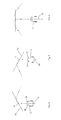
- Figure 3 is a structural view of the robot mower of the robot mower system.
- the autonomous vehicle comprises a housing 21, and a driving module, a working module, a limit detecting module, an energy module, a control module, etc. installed on the housing.
- the driving module comprises a wheel set installed below the housing.
- the wheel set comprises driving wheels.
- Two driving wheels are respectively located on the two sides in the rear of the housing 21.
- the wheel set also comprises auxiliary wheels 25.
- Two auxiliary wheels are respectively located on the two sides on the front of the housing 21.
- the driving module also comprises a driving motor connected with the driving wheels.
- the driving motor is responsible for driving the driving wheels 23 to rotate to bring the robot mower 11 to move and also responsible for driving the driving wheels 23 to perform turning.
- two driving wheels 23 are respectively connected with a driving motor.
- the rotation speed of the driving motor is controlled by the control module.
- the robot mower 11 moves along a straight line; when the control module orders the two driving motor to rotate at different speeds or in different directions, the robot mower 11 performs turning towards the side on which the driving wheels rotates at a slower speed or the side on which the driving wheel goes back.
- the working module comprises a cutting module 29 installed below the robot mower and a cutting motor 31 for driving the cutting module 29 to mow grasses.
- the cutting module 29 can be a blade connected to the mowing output shaft or a combination of a cutter and a blade connected to the mowing output shaft, and the specific structure thereof may be known for those skilled in the art and therefore is not described in detail.
- the limit detecting module are border sensing elements 35 installed in the housing 21.
- the robot mower has a longitudinal central axis 33.
- the central axis 33 drives the housing 21 into two sides, namely left side and right side.
- the border sensing elements 35 are electric inductors (inductors for short) respectively installed on two sides of the central axis 33.
- two electric inductors are symmetrically installed on two sides of the central axis 33, at the front part of the housing 21.
- the advantage that the electric inductors are located at the front is that the border signal can be sensed more quickly and accurately.
- the limit detecting module is connected with the control module to transmit the monitored border signal to the control module.
- more the electric inductors also can be located in the middle part or rear part of the housing 21 to increase the accuracy of the border signal identification.
- the energy module is a chargeable battery located in the housing 21, and a charging electrode connected with the chargeable battery.
- the charging electrode is located at the front part of the housing and exposed out of the housing 21 for docking with the corresponding charging electrode of the dock 5 when the robot mower 11 enters the dock 5 and charging the robot ower 11.
- control module 11 is located in the housing 21, comprising a microcontroller, a memory, etc.
- the memory is used for storing the working programs of the robot mower and the related parameters of the robot mower in the working process, information fed back by other modules, etc.
- the microcontroller is used for receiving signal sent from other systems and the programs built in the memory, performing calculation and sending corresponding working orders to the modules.
- the robot mower 11 also comprises an obstacle monitoring module which is specifically a collision sensor installed on the housing.
- an obstacle monitoring module which is specifically a collision sensor installed on the housing.
- the collision sensors detect collision, generate collision signals and transmit the collision signals to the control module.
- the robot mower 11 also comprises a control panel for setting the working mode by the operator. More details are not described here.
- the working mode of the autonomous mowing system is briefly introduced below.
- the robot mower 11 cruises and mows grasses in the working scope surrounded by the border line 13.
- the autonomous mower 11 moves in a straight way until colliding with the limit, namely the border line 13 or the obstacle 17. If collides with the border line 13 or the obstacle, the robot mower 11 performs turning, returns back into the limit, and keeps moving straightly until colliding with the limit again.
- the robot mower 11 works in the whole working area 7 by the mentioned way of continuously moving back in the limit.
- the control module controls the robot mower 11 to seek the border line 13 and move along the border line 13.
- the dock 5 is located on the border line 13, so the robot mower 11 moves back into the dock 5 along the border 13 and then is docked and charged or berthed in the dock 5.
- the autonomous vehicle 1 inevitably collides with the limit after moving for a period of time.
- the mutual relative location relationship is the mentioned angle relationship, interior-exterior relationship, angle relationship, etc.
- the limit detecting module sends the signals such as the approach degree signal and/or angle relationship signal that represents those location relationships to the control module.
- the autonomous vehicle performs turning to move away from the limit after moving towards the limit and reaching a predetermined location relationship to ensure not leaving the working scope.
- the signal received by the control module from the limit detecting module may represent the angle relationship between the autonomous vehicle and the limit, the side of the autonomous vehicle close to the limit, or several of the mentioned items. This depends on how to interpret the signal sent from the limit detecting module.
- the mentioned predetermined location relationship relates to the startup conditions of turning and other vary with the specific autonomous working system.
- the predetermined location relationship is that the robot mower 11 has been already collided with the border line, while one electric inductor is located directly above the border line 13, namely the distance from a certain border sensing element to the limit reaches 0 predetermined distance.
- the border is usually a wall, so the predetermined location relationship is usually a distance from the front end of the autonomous dust collector to the border, such as 30cm.
- those examples are schematic, and the predetermined location relationship is set according to the specific demands.
- the central axis of the autonomous vehicle inevitably forms an intersection point with the limit, and in the situation of not vertically approaching the limit, one side of the autonomous vehicle inevitably is closer to the limit. Then, when the central axis of the autonomous vehicle 1 forms an acute angle with the left or right border line of the intersection point when it is not vertical to the limit, and the autonomous vehicle turning in the direction where the acute angle is reduced can efficiently turn to the limit at a relatively small angle. More abstractly speaking, the autonomous vehicle monitors the location relationship between it and the limit, and the control module makes the driving module to perform turning according to the signal representing the angle relationship between the autonomous vehicle and the limit transmitted from the limit detecting module, so the turning is quicker and more efficient.
- the control module makes the driving module to make a turn in the direction where the acute angle or right angle between the central axis and the limit is reduced, and always keeps that the central axis of the autonomous vehicle always form an acute angle or a right angle with one side of the limit, while the other side of the limit forms an acute angle or right angle with the central axis of the autonomous vehicle when the turn begins.
- the mentioned process can also be understood that the autonomous vehicle monitors the location relationship between it and the limit, judges which side of it is closer to the limit when reaching a predetermined location relationship with the limit, and performs turning clockwise if the left side is closer to the limit, otherwise performs turning anticlockwise if the right side is closer to the limit; moreover, the turning result is always that the distance from one side of the autonomous vehicle to the limit is smaller than that from the other side to the limit, while said one side is closer to the limit when the turn begins.
- the two descriptions are different in mode, but consistent in nature. It should be understood that the signal parameters sent by the limit detecting module physically correspond to different scenes.
- Figure 4, figure 5 and figure 6 are path selecting diagrams of the robot mower 11 after reaching the limit.
- the moving direction of the robot mower 11 is identical, and the extension direction of the central axis 33 is identical when the robot mower collides with the border line 13, but the extension direction of the border line 13 in different in the figures, so the turning direction and result are different.
- the dotted line passing through the robot mower 11 is the moving track of the robot mower 11.
- central axis 33 of the robot mower 11 forms an intersection point 41 with the border line 13
- central axis 33 forms an angle with each of the two border lines 13 of the intersection point 41, and the sum of the two angles is 180 degrees.
- the border lines 13 or the limit may be bent in an overall view, but the border line 13 near an intersection point or the limit may be regarded as a straight line; or it can be said that, the border line 13 or the limit may be bent, but at the predetermined distance for judging the turn, namely the intersection between the central axis 33 and the border line 13 or the limit, the border line 13 or the limit is a straight line in the extension direction, and the extension direction is the tangent line of the border line 13 and the limit.
- the robot mover 11 is preferably symmetrically provided with two a border sensing element 35 on two sides of the central axis 33.
- the left side will collides with the border line 13 first, namely the left border sensing element 35 will sense collision with the border line 13 first and sends a collision signal to the control module that represents that the left side of the robot mower 11 collides with the border line 13.
- the control module receives the left collision signal first and correspondingly judges that the robot mower moves to the border line 13 from the left side of the intersection point of the border line 13 and the robot mower 11, and the central axis 33 of the robot mower 11 forms an acute angle with the border line 13 on the left side of the collision intersection point.
- the border sensing element on one side first sends a signal representing that it reaches a predetermined distance from the limit to the control module, and then the control module judges that the limit on one side of the central axis forms an acute angle with the central axis.
- the border sensing element on one side first sends the signal representing that it goes out of the limit to the control module, and then the control module judges that the limit on one side of the central axis forms an acute angle with the central axis.
- the robot mower 11 After the moving direction of the robot mower 11, or the orientation relationship between the central axis 33 of the robot mower 11 and the border line 13 during the collision is determined, the robot mower 11 correspondingly determines the turning direction and turns right, namely the robot mower 11 turns in the direction to reduce the acute angle between the central axis 33 thereof and the border line 13.
- the control module of the robot mower 11 controls the driving module, and then the rotation speed of the left driving wheel 23 is bigger than that of the right driving wheel 23, so the robot mower 11 turns right and returns into the working scope 7.
- the turning angle is fixed, greater than or equal to 90 degrees and less than 180 degrees, preferably a little greater than 90 degrees, between 90 degrees and 120 degrees. The reason that the turning angle is greater than or equal to 90 degrees is to ensure that robot mower 11 moves into the limit when the above mentioned acute angle value is undetermined. If this angle vale is determined, the corresponding appropriate turning angle within 180 degrees can be selected according to the acute angle value, which is described in detail in the text below.
- the other border sensing element 35 of the robot mower 11 may sense collision with the border line 13 and then sends the collision signal to the control module.
- the border line 13 of the robot mower system is configured to be a little closer to the inside of the lawn than the physical working scope, so the robot mower 11 does not exceed the actual physical working scope when turning.
- the extension direction of the border line 11 is different from that in figure 4 , so the turning direction is different even through the robot mower 1 faces the same direction.
- the right side of the robot 11 collides with the border line 13 first, namely the right border sensing element 35 senses collision with the border line 11 first, and sends a collision signal to the control module to represent that the right side of the robot mower 11 collides with the border line.
- the control module receives the right collision signal first, and correspondingly determines that the robot mower moves towards the border line from the right side of the intersection point of the border line and the robot mower, and the central axis of the robot mower 11 forms an acute angle with the right border line of the collision intersection point.
- the robot mower 11 After determining the moving direction of the robot mower 11 or the orientation relationship between the central axis 33 of the robot mower and the border line 13 during collision, the robot mower 11 correspondingly determines the turning direction and anticlockwise turns left, namely the robot mower 11 turns in the direction to reduce the acute angle between the central axis 33 and the border line 13.
- the control module of the robot mower 11 controls the driving module, so the rotation speed of the right driving wheel 23 is greater than that of the left driving wheel 23, and the robot mower 11 turns left to return into the working scope.
- the extension direction of the border line 13 is vertical to the moving direction of the robot mower 11 or the central axis 33 of the border line 13 during collision.
- the two border sensing elements 35 of the robot mower 11 sends the collision signal to the control module, and the control module determines that the robot mower 11 vertically moves towards the border line and then controls the moving system to turn randomly.
- the moving track of the robot mower 11 crosses the border line 13.
- the intersection point of the central axis 33 and the border line 13 is O when robot mower 11 crosses the border line 13, and is P when the turn is completed and the robot mower goes back into the limit.
- the intersection point of the central axis 33 of the robot mower 11 or the moving track and one side of the border line 13 form an acute angle O, as shown in the figure.
- the control module controls the robot mower 11 to turn in the direction where the acute angle is reduced, and keep moving during turning, leave the limit, return into the limit, and completes the turn after going back into the limit.
- intersection point of the central axis 33 of the robot mower 11 and the border line 13 also forms an acute angle P, as shown in the figure.
- the extension direction of one side of the angle P starting from P that is located on the border line is opposite to that of the angle O starting from O that is located on the border line.
- the predetermined location relationship for triggering turning is that the predetermined distance is zero, so the track line is intersected with the border line.
- the peak of the included angle between the central axis 33 of the robot mower 11 and the border line 13 separates before and after the turning. But it is easily understood that the track line translates vertically according to the different predetermined distance, while the intersection point of the track line and the border line 13 changes, even is superposed or disappears, but the two included angles between the central axis 33 and the two border lines 13 are not changed.
- each border line 13 is divided into two sides extending in two directions from the intersection point of the central axis 33 and each border line 13 when the turning is triggered, and then the central axis 33 forms an acute angle with one of the sides before turning and forms an acute angle with the opposite other side extending in the other direction after turning.
- the robot mower 11 vertically collides with the border line 13, then forms an acute angle with one of the sides after turning, and forms an acute angle with the opposite side extending in the other direction after turning.
- one side of the robot mower 11 collides with the border line first, and the other side of the robot mower 11 keeps a certain distance from the border line 13 during collision. As shown in the figure, the distance is do.
- the robot mower 11 starts turning at this moment. As mentioned above, if the left side collides with the border line first, the robot mower 11 turns right; if the right side collides with the border line first, the robot mower 11 turns left, meaning if one of the sides collides with the border line first, the robot mower turns in the other side.
- the distance from the side of the robot mower that collides with the border line first to the border line 13 or the extension line of the border line 13 is d 1
- the distance from the other side to the border line 13 or the extension line of the border line 13 is d 2 when the turn is completed and the robot mower 11 enters the limit.
- d 1 is smaller than d 2 after meaning that the robot mower 11 keeps that the side colliding with the border line first closer to the border line than the other side after the turn is completed.
- the limit detecting module sends a signal to the control module when detecting that one side of the housing 21 and the limit reach the predetermined distance first, and the control module controls the driving module to bring the autonomous vehicle 1 to turn from one side to the other side.
- the distance from said one side of the autonomous vehicle 1 to the limit is smaller than that from said the other side to the limit.
- the included angle between the robot mower 11 keeping turning and the other side of the intersection point is also an acute angle, or the robot mower turns into the working scope at a small angle which is at most 180 degrees on the premise that the distance from one side of the robot mower that first approaches the border line to the limit is smaller than that from the other side to the limit. If the robot mower turns in the other direction, the turning angle is at least 180 degrees to reach the identical final angle.
- the above mentioned turning mode makes the robot mower 1 moves in a direction finally. If the working scope is divided into two parts by the line vertical to the limit at the intersection point of the autonomous vehicle 1 and the limit, then the autonomous vehicles moves from the original part to another part after the turning instead of staying in the original part. In this way, the autonomous vehicle frequently cruises in different areas to increase the coverage efficiency of the working scope, and more easily goes out of the complicated area.
- the determining of the limit detecting module on the angle is qualitative, only determining which side of the robot mower collides with the border line first; then correspondingly, the other side turns, and the turning angle does not exceed 180 degrees; or the limit detecting module only judges which border side of the intersection point 41 forms an acute angle with the autonomous mower 11, and then the robot mower 11 correspondingly turns in the direction where the acute angle is reduced, finally forms an acute angle with the other side, and keeps moving straightly.
- the determining of the limit detecting module on the angle is quantitative, namely monitoring the value of the included angle between the central axis of the robot mower and the border line when the collision is determined.
- the realization mode is as mentioned below:
- the robot mower 11 is provided with a displacement monitoring element for monitoring the moving distance of the robot mower in a period of time.
- the displacement and the speed are related parameters, so the robot mower 11 monitors the displacement of the robot mower through monitoring the moving speed.
- the displacement monitoring speed specifically may be a speed sensor for monitoring the rotation speed of the driving wheels, or an acceleration speed for directly monitoring the speed of the robot mower 11, or other elements capable of monitoring the speed of the robot mower 11.
- the two border sensing elements 35 of the robot mower 11 collide with the border lines in succession and respectively send the collision signals to the control module.
- the displacement monitoring element monitors the displacement in the period that the border sensing elements collide with the border lines in succession.
- the distance between the two border sensing elements 35 is a known fixed value, so the included angles between the robot mower 11 and the border lines 13 can be calculated according to the distance between the two border sensing elements and the displacement of the robot mower 11 when the two border sensing elements 35 passes the border lines in succession.
- the control module records the moving distance of the autonomous moving distance in the period of time when the two border sensing elements respectively send the signals representing that they reach a predetermined distance with the limit, or the two border sensing elements respectively send signals representing that they cross the limit, and calculates the value of the included angle between the central axis and the limit. Then, the control module can correspondingly calculate an appropriate turning angle according to the included angle, make the robot mower 11 to keep a fixed angle when leaving the border line or at variable angles. In the case that the angle value can be calculated, the turning angle may be smaller than 90 degrees.
- the signal of the island 15 is identical with that of the border line 13, both of them are periodical current signals, so the robot mower 11 determines the direction when colliding with the island 15 in a way identical to that when colliding with the border line 13 and leaves the island 15 when turning.
- the robot mower 11 can be also provided with a set of obstacle sensing modules for finding the obstacle 17 before collision and perform turning.
- the obstacle sensing modules can also monitor the angle of the robot mower 11 when colliding with the obstacle 17 so as to perform turning in the mode similar to the mentioned case of collision with border line 13, thus improving the efficiency.
- the obstacle sensing modules can be an ultrasonic wave transmitting element installed on the robot mower 11 or two ultrasonic wave reducing elements respectively located on the two sides of the robot mower, judging the distance from the obstacle and the angle through the difference between the time that the two ultrasonic wave receiving elements on the two sides receive the reflected ultrasonic wave signals.
- the determining of the limit detecting module on the angle may be qualitative or quantitive. Being qualitative refers to that the limit detecting module only judges which side of the intersection point forms an acute angle with the autonomous vehicle 1, and then the autonomous vehicle 1 turns in the direction where the acute angle is reduced and keeps forming an acute angle with the other side after turning. Being quantitive refers to that the limit detecting module can determine the accurate angle between the autonomous vehicle and the limit, and then the autonomous vehicle turns in a direction where the acute angle is reduced, and selects the turning angle according to the specific turning angle to fulfill the aim of optimizing the turning angle. Optimizing the turning angle may refer to reducing the turning, ensuring that the springing angle in a certain scope, or optimizing the path to increase the coverage rate or reduce the return times.
- the limit 3 may be various, a wall in a house or other photo-optical signals, and shall not be limited to the current type border line signal or obstacle.
- the limit detecting modules vary with the property of the limit 3, such as the infrared sensor, ultrasonic wave sensor, etc.
- the tangible limit can realize turning, and the autonomous vehicle cannot collide with the limit, so the distance between the predetermined turning site and the actual limit may be relatively long, and the sensor is the remote type to ensure no collision with the limit 3 during turning.
- the predetermined turning distance is relatively short, and the autonomous vehicle turns when approaching or already colliding with the border. Due to inertia, the real turning track may be intersected with the limit.
- the turning determining point of the signal type limit 3 may be set like that of the tangible limit, keeping a certain distance. Therefore, the autonomous vehicle is not intersected with the limit when turning, meaning that the distance from the autonomous vehicle 11 to the limit is greater than or equal to 0 when turning.
- the ways for determining the distance and angle between the autonomous vehicle 1 and the border line are not limited to those described in the specific embodiments, and may other others such as the GPS navigation system similar to the car navigation and the image acquisition technology.
- the memory of the control module is internally provided with the map of the working scope and the location and direction of the border line
- the autonomous vehicle is internally provided with the GPS navigation module, and then the angle and distance can be determined according to the map information and the GPS information when the autonomous vehicle collides with the border line, and then the mentioned turning mode is employed.
- the autonomous vehicle is equipped with a camera, and it is feasible to judge the collision direction and distance by identifying the image of the environment. In the present invention, the more important is to determine the turning strategy and direction after turning.
- the robot mower 11 realizes the angle judgment and turning direction determination through the border sensing elements on the two sides of the housing 21.
- the principle of determining the turning direction through one sensor is described with reference to figure 9 .
- the robot mower 11 crosses the border line. After colliding with the border line, the turning angle of the robot mower 11 is fixed, so the turning track is basically fixed, as shown by the dotted line. However, the direction of the border line 13 is unknown.
- the locations of three typical border lines 13 are shown in the figure. Providing that the border lines 13 are vertical to the moving direction of the robot mower 11 or the central axis direction during collision, and then the robot mower 11 forms an intersection point O with the border line 13 when going out of the limit and the intersection point P when going back into the limit, and the moving path of the robot mower 11 is an arc line OP.
- the length of the arc lien OP may be a reference length for judging the angle relationship between the central axis and the border line 13 when the robot mower 11 collides with the border line. If the robot mower 11 forms an acute angle with the left side of the intersection point of the border line 13, then the two intersection points of the robot mower 11 are as shown by the arc line OA, and the length of OA is smaller than that of OP; if the robot mower 11 forms an obtuse angle with the left side of the intersection point of the border line 13, the two intersection points of the robot mower 11 are as shown by the arc line OB, and the length of OB is greater than that of OP.
- the angle relationship between the robot mower 11 and the border line 13 an be obtained by detecting the moving distance when the robot mower 11 goes out and goes into the limit and comparing the moving distance with OP. Then, corresponding action can be adopted, such as turning again when the moving distance is greater than OP.
- the robot mower 11 moves towards the border line 13 until sensing that it is located above the border line 13.
- the border sensing element 35 sends the collision signal to the control module.
- the control module After the receiving the collision signal, the control module sends an order to the driving module to turn at a predetermined angle and move towards the limit. In such circumstance, the control module cannot judge whether this turning direction is the direction where the non-obtuse angle between the central axis 33 of the robot 11 and the border line 13 is reduced, and the robot mower 11 keeps moving, so the border sensing element 35 crosses the border to go outside.
- the border sensing element 35 returns into the limit from the outside, and passes the border line 13 from the above.
- the control module records the time cost when the border sensing element crosses the border line 13 twice, compares the time with one or more reference time, judges that the turning faces the acute angle between the central axis 33 and the border line 13 when the robot mower 11 collides with the border line if the time is smaller than a predetermined first reference time, that the turning faces the direction where the right angle between the central axis 33 and the border line 13 is reduced when the robot mower 11 collides with the border line if the time is equal to the reference time or is between two preference time, and that the turning faces the direction where the obtuse angle between the central axis 33 and the border line 13 is reduced when the robot mower 11 collides with the border line if the time is greater than a preference time.
- the robot mower 11 can adopt the corresponding actions, for example controlling the robot mower 11 to perform turning reversely on condition that the turning faces the direction where the obtuse angle between the central axis 33 and the border line 13 is reduced when the robot mower 11 collides with the border line, so the moving direction of the robot mower 11 or the central axis 33 after turning form an acute angle with the border line 13 which forms an obtuse angle with the central axis when the robot mower 11 collides with the border line.
- the robot mower 11 is provided with a displacement detecting element for detecting the moving distance of the robot mower 11 at the interval that the border sensing element 35 of the robot mower 11 crosses the border line twice, comparing the distance with one or more reference distances and then determines the turning direction.
- the process and direction are similar to those in comparison with the reference time and therefore are not described in detail.
- the robot mower 11 can record the time interval of crossing the border line twice and the moving distance to increase to the accuracy of judgment.
- the mentioned turning method also keeps the robot mower moving in the whole turning process, and the direction leaving the border line forming an acute angle with the border line 13 which forms an obtuse angle with the central axis 33 when the robot mower 11 collides with the border line. It is of directivity, obviously prior to the prior art.
- Figure 10 and figure 11 are respectively path comparison diagrams of the autonomous vehicle passes through the narrow areas on condition that the path planning mode is not used and used, and the dotted line is the moving path. It can be obviously seen that, it is very difficult for the autonomous vehicle 1 to leave the narrow area when the path planning mode is not used, and the autonomous vehicle 1 may ably leave the narrow after turning around; moreover, the leaving time is unknown. If the path planning mode is employed, the autonomous vehicle 1 has a direction and can leave the narrow area after turning around for limited times. Actual calculation shows that, in a typical narrow area, it costs an average time of 5min for the autonomous vehicle to leave the narrow area if the path planning mode is not used, and 30s if the path planning method is used.
- the autonomous vehicle 1 of the present invention can greatly reduce the stopping/braking times.
- the autonomous vehicle keeps moving or the driving motor keeps driving the wheel set, thereby greatly improving the overall efficiency of the mower, saving energy, protecting the environment, prolonging the service life of the battery, and cutting more grasses or doing more work in a unit time.
- the autonomous vehicle 1 can do 20% of extra work on the same condition of full power after the path planning mode is employed, effectively using the inertia thereof and achieving a very good energy-saving effect. Meanwhile, in the same working time, the moving distance of the autonomous vehicle adopting the path planning mode is 35% greater than that of the autonomous vehicle not adopting the path planning mode, so the working efficiency is greatly improved. To improve the working efficiency to the maximum extent, the autonomous vehicle 1 has such a mode in which the mower always keeps moving and never stops during turning when carrying out the work tasks.
- the mentioned turning mode may be one of a plurality of the path planning modes of the autonomous vehicle. The autonomous vehicle enables this mode only when detecting that it locates in the narrow area or corner area.
- the detecting mode may be: quickly colliding with the border for several times, or colliding the border line for predetermined times in a predetermined time period.
- the specific embodiment of the present invention also provides another path planning mode.
- Such path planning mode makes the autonomous vehicle quickly leave the narrow area by moving along the limit 3 for a distance after encountering the limit 3. After approaching the limit 3, the autonomous vehicle rotates slightly first to adjust the moving direction to be consistent with the extension direction of the limit 3, then moves at a predetermined distance along the extension direction of the limit 3, and turns towards the limit 3 again. After the turn begins and before the turn is completed, the autonomous vehicle moves for a distance.
- the specific way of moving for a distance may be that the autonomous vehicle moves for a predetermined time or a predetermined distance, and the predetermined distance is 20cm-100cm.
- Figure 9 is a schematic view of the moving path of the robot mower 11 adopting the path planning mode.
- the robot mower 11 has border sensing elements 35 located on two sides of the housing 21. After moving for a distance, the robot mower 11 collides with the border line 13. In the case of non-vertical collision, one border sensing element 35 collides with the border line first and sends the collision signal to the control module.
- the control module correspondingly judges the angle relationship between the central axis 33 of the robot mower 11 and the border line 13, then gives an order to the driving module to turn in a direction where the acute angle or right angle between the central axis 33 and the border line 13 is reduced.
- the border sensing element 35 which previously crossed the border line 13 moves back into the limit, while the other border sensing element 35 still locates out of the limit.
- the robot mower stops turning and starts to move along the border line 13.
- the control module corrects the moving direction at any time to ensure that the mentioned one border sensing element 35 locates in the limit and the mentioned other border sensing element 5 locates out of the limit, namely ensuring the magnetic fields of two electric inductors are opposite.
- the robot mower 11 always locates in the limit on one side, and out of the limit on the other side, realizing moving cross and along the border line 13.
- the magnetic fields sensed by the two electric inductors are identical, and the robot mower correspondingly rotates slightly in a direction to make the side move back into or out of the limit, so the magnetic fields sensed by the two electric inductors are kept opposite.
- the control module controls the driving module to keep the distances between the two electric inductors and the border lines equal.
- the mentioned mode of moving across the border line and the quantity of the electric inductors are not necessary.
- the autonomous vehicle can also move along the border line. The distance may be 10cm. In this occasion the autonomous vehicles moves on the border line.
- the control module but only monitors the intensities, but also the directions of the magnetic fields sensed by the two electric inductors, and keeps the directions of the magnetic fields sensed by the two electric inductors opposite and intensities equal. In this way, the distances from the two electric inductors to the border lines 13 are kept equal, realizing that the robot mower 11 moves along the straight line.
- the control module of the robot mower 11 orders the driving module to perform turning again to leave the border line 13 and move back into the limit.
- the turning direction towards the direction of the first turning, and the turning angle is smaller than or equal to 90 degrees.
- the mentioned turning mode approximately has three steps: turning for the first time, moving along the border line, and turning for the second time.
- omitting the first step is also feasible, meaning that the robot mower 11 directly moves along the border line after colliding with the border line.
- the effect of the first turning is achieved by correcting the direction of moving along the border line.
- the limit 2 may be a border or an obstacle.
- the border may be a lead with a current signal, a physical border, or other borders formed by acoustic and optical signals.
- the included angle between the central axis 33 in the autonomous vehicle 1 and the limit 3 may be the border sensing elements 35 on the sides in this embodiment, the GPS navigation system or other feasible systems.
- the way of moving along the border line may move across the border line in this embodiment, or move for a predetermined distance against the border line.
- the predetermined distance for moving along the border line is preferably 20-100cm in this embodiment, but can be correspondingly according to the working property of the autonomous vehicle 1 and the size, shape and features of the map, or freely set by the operator.
- the autonomous vehicle 1 Through moving for a distance along the border line 13 and leaving the border line along the original direction, the autonomous vehicle 1 further improves the efficiency of leaving the narrow areas. As shown in figure 8 and figure 9 , the turning times and moving distance for leaving the narrow area are smaller in the mode of moving along the border line first and then perform turning.
Priority Applications (1)
| Application Number | Priority Date | Filing Date | Title |
|---|---|---|---|
| EP21156267.3A EP3876068A1 (fr) | 2011-04-28 | 2012-04-27 | Système automatique, dispositif de marche automatique et sa méthode de conduite |
Applications Claiming Priority (2)
| Application Number | Priority Date | Filing Date | Title |
|---|---|---|---|
| CN201110109287 | 2011-04-28 | ||
| PCT/CN2012/074845 WO2012146195A1 (fr) | 2011-04-28 | 2012-04-27 | Système automatique, dispositif de marche automatique et sa méthode de conduite |
Related Child Applications (1)
| Application Number | Title | Priority Date | Filing Date |
|---|---|---|---|
| EP21156267.3A Division EP3876068A1 (fr) | 2011-04-28 | 2012-04-27 | Système automatique, dispositif de marche automatique et sa méthode de conduite |
Publications (3)
| Publication Number | Publication Date |
|---|---|
| EP2703925A1 true EP2703925A1 (fr) | 2014-03-05 |
| EP2703925A4 EP2703925A4 (fr) | 2015-12-30 |
| EP2703925B1 EP2703925B1 (fr) | 2021-02-24 |
Family
ID=47054402
Family Applications (2)
| Application Number | Title | Priority Date | Filing Date |
|---|---|---|---|
| EP12776927.1A Active EP2703925B1 (fr) | 2011-04-28 | 2012-04-27 | Système automatique, dispositif de marche automatique et sa méthode de conduite |
| EP21156267.3A Pending EP3876068A1 (fr) | 2011-04-28 | 2012-04-27 | Système automatique, dispositif de marche automatique et sa méthode de conduite |
Family Applications After (1)
| Application Number | Title | Priority Date | Filing Date |
|---|---|---|---|
| EP21156267.3A Pending EP3876068A1 (fr) | 2011-04-28 | 2012-04-27 | Système automatique, dispositif de marche automatique et sa méthode de conduite |
Country Status (5)
| Country | Link |
|---|---|
| US (3) | US9983586B2 (fr) |
| EP (2) | EP2703925B1 (fr) |
| CN (5) | CN102768534B (fr) |
| DK (1) | DK2703925T3 (fr) |
| WO (1) | WO2012146195A1 (fr) |
Cited By (7)
| Publication number | Priority date | Publication date | Assignee | Title |
|---|---|---|---|---|
| EP3056959A1 (fr) * | 2015-02-10 | 2016-08-17 | Honda Motor Co., Ltd. | Appareil de commande de véhicule utilitaire à navigation autonome |
| EP3225096A1 (fr) * | 2016-03-31 | 2017-10-04 | Honda Motor Co., Ltd. | Appareil de commande pour véhicule utilitaire |
| CN107346134A (zh) * | 2017-08-29 | 2017-11-14 | 北京矿冶研究总院 | 一种地下矿用铰接式车辆无人驾驶控制方法及装置 |
| EP2806325B1 (fr) | 2013-04-09 | 2018-03-21 | F. Robotics Acquisitions Ltd. | Système robotique domestique |
| US10139821B2 (en) | 2015-03-27 | 2018-11-27 | Honda Motor Co., Ltd. | Control apparatus for autonomously navigating utility vehicle |
| SE2150161A1 (en) * | 2021-02-15 | 2022-08-16 | Husqvarna Ab | Improved navigation for a robotic work tool |
| EP4043986A4 (fr) * | 2019-11-15 | 2022-11-09 | Nanjing Chervon Industry Co., Ltd. | Système de tondeuse intelligente |
Families Citing this family (130)
| Publication number | Priority date | Publication date | Assignee | Title |
|---|---|---|---|---|
| DK2703925T3 (da) | 2011-04-28 | 2021-05-10 | Positec Power Tools Suzhou Co Ltd | Automatisk arbejdssystem, automatisk gangindretning og styrefremgangsmåde dertil |
| JP5836151B2 (ja) * | 2012-02-10 | 2015-12-24 | 本田技研工業株式会社 | 無人走行作業車用エリアワイヤの配置構造およびその制御装置 |
| CN103838238B (zh) * | 2012-11-23 | 2017-08-01 | 苏州宝时得电动工具有限公司 | 自动工作系统 |
| CN102960113A (zh) * | 2012-12-03 | 2013-03-13 | 张思凡 | 一种可遥控剪草机 |
| CN103891464B (zh) * | 2012-12-28 | 2016-08-17 | 苏州宝时得电动工具有限公司 | 自动割草系统 |
| US9820433B2 (en) | 2012-12-28 | 2017-11-21 | Positec Power Tools (Suzhou Co., Ltd.) | Auto mowing system |
| US9956687B2 (en) | 2013-03-04 | 2018-05-01 | Microsoft Technology Licensing, Llc | Adapting robot behavior based upon human-robot interaction |
| JP6233706B2 (ja) * | 2013-04-02 | 2017-11-22 | パナソニックIpマネジメント株式会社 | 自律移動装置及び自律移動装置の自己位置推定方法 |
| CN104111651A (zh) * | 2013-04-22 | 2014-10-22 | 苏州宝时得电动工具有限公司 | 自动行走设备及其向停靠站回归的方法 |
| CN104252175B (zh) * | 2013-06-28 | 2017-09-22 | 苏州宝时得电动工具有限公司 | 自动工作系统及其抗信号干扰的方法 |
| CN104345734A (zh) * | 2013-08-07 | 2015-02-11 | 苏州宝时得电动工具有限公司 | 自动工作系统、自动行走设备及其控制方法 |
| WO2015018355A1 (fr) * | 2013-08-07 | 2015-02-12 | 苏州宝时得电动工具有限公司 | Système automatique d'exécution de tâches, dispositif de déplacement automatique et son procédé de commande |
| US9096199B2 (en) * | 2013-10-09 | 2015-08-04 | Ford Global Technologies, Llc | Monitoring autonomous vehicle braking |
| CN104737698A (zh) * | 2013-12-27 | 2015-07-01 | 苏州宝时得电动工具有限公司 | 自动割草机 |
| DE102014104619A1 (de) * | 2014-04-02 | 2015-10-08 | Claas Agrosystems Kgaa Mbh & Co. Kg | Planungssystem und Verfahren zur Planung einer Feldbearbeitung |
| JP6378962B2 (ja) * | 2014-07-31 | 2018-08-22 | シャープ株式会社 | 自走式電子機器 |
| CN105511456A (zh) * | 2014-09-23 | 2016-04-20 | 苏州宝时得电动工具有限公司 | 自动行走设备控制方法及自动工作系统 |
| US20160128275A1 (en) * | 2014-11-12 | 2016-05-12 | Deere & Company | Robotic mower contact detection system |
| EP3222391B1 (fr) | 2014-11-19 | 2020-04-22 | Positec Technology (China) Co., Ltd. | Robot automoteur |
| US9420741B2 (en) | 2014-12-15 | 2016-08-23 | Irobot Corporation | Robot lawnmower mapping |
| SE1451644A1 (sv) * | 2014-12-23 | 2016-05-31 | Husqvarna Ab | Improved map generation by a robotic work tool |
| CN104515520B (zh) * | 2014-12-25 | 2017-06-16 | 中联重科股份有限公司 | 一种农用机械的转弯预警方法、装置及农用机械 |
| CN105988470A (zh) * | 2015-02-15 | 2016-10-05 | 苏州宝时得电动工具有限公司 | 自动割草机 |
| CN105988472B (zh) * | 2015-02-16 | 2020-03-27 | 苏州宝时得电动工具有限公司 | 智能割草系统、智能割草机及其修边方法 |
| JP6014192B1 (ja) * | 2015-03-27 | 2016-10-25 | 本田技研工業株式会社 | 無人作業車の制御装置 |
| WO2016184398A1 (fr) * | 2015-05-19 | 2016-11-24 | 苏州宝时得电动工具有限公司 | Système et procédé d'identification de signal d'impulsion de ligne de délimitation et système de tonte intelligent |
| EP3302020B1 (fr) | 2015-05-27 | 2020-04-08 | MTD Products Inc | Groupe de couteaux pour tondeuse autonettoyant |
| US9598078B2 (en) | 2015-05-27 | 2017-03-21 | Dov Moran | Alerting predicted accidents between driverless cars |
| US10031522B2 (en) | 2015-05-27 | 2018-07-24 | Dov Moran | Alerting predicted accidents between driverless cars |
| USD794089S1 (en) | 2015-06-05 | 2017-08-08 | Mtd Products Inc | Wheel |
| USD797530S1 (en) | 2015-06-05 | 2017-09-19 | Mtd Products Inc | Blade |
| USD760806S1 (en) | 2015-06-05 | 2016-07-05 | Mtd Products Inc | Robotic mower |
| USD758455S1 (en) | 2015-06-05 | 2016-06-07 | Mtd Products Inc | Robotic mower body |
| CN106561148B (zh) * | 2015-10-13 | 2020-04-14 | 苏州宝时得电动工具有限公司 | 智能割草机 |
| USD792198S1 (en) | 2015-10-29 | 2017-07-18 | Mtd Products Inc | Caster wheel |
| DE102015222414A1 (de) * | 2015-11-13 | 2017-05-18 | Robert Bosch Gmbh | Autonomes Arbeitsgerät |
| CN106982585B (zh) * | 2016-01-21 | 2019-06-04 | 苏州宝时得电动工具有限公司 | 履带式割草机及其转向方法 |
| WO2017133707A1 (fr) * | 2016-02-06 | 2017-08-10 | 苏州宝时得电动工具有限公司 | Système automatique de fonctionnement, dispositif automoteur et son procédé de commande |
| USD795299S1 (en) | 2016-02-16 | 2017-08-22 | Mtd Products Inc | Blade |
| USD781349S1 (en) | 2016-02-16 | 2017-03-14 | Mtd Products Inc | Robotic mower housing |
| JP6243944B2 (ja) * | 2016-03-18 | 2017-12-06 | 本田技研工業株式会社 | 無人走行作業車 |
| JP6235640B2 (ja) * | 2016-03-18 | 2017-11-22 | 本田技研工業株式会社 | 無人走行作業車 |
| CN107291071A (zh) * | 2016-03-30 | 2017-10-24 | 苏州宝时得电动工具有限公司 | 自动工作系统、自动行走设备及其转向方法 |
| EP3445153B1 (fr) | 2016-04-20 | 2021-08-11 | MTD Products Inc. | Système de lame à faible énergie comportant un mécanisme de fixation rapide |
| CN107402573B (zh) * | 2016-05-19 | 2021-05-14 | 苏州宝时得电动工具有限公司 | 自动工作系统,自移动设备及其控制方法 |
| CN107493797B (zh) * | 2016-06-14 | 2020-03-27 | 苏州宝时得电动工具有限公司 | 位置识别系统 |
| EP3597024B1 (fr) | 2016-06-24 | 2021-03-24 | MTD Products Inc | Système de coupe à haut rendement |
| USD848488S1 (en) | 2016-08-23 | 2019-05-14 | Mtd Products Inc | Robotic mower housing |
| USD795300S1 (en) | 2016-08-23 | 2017-08-22 | Mtd Products Inc | Blade |
| US9807930B1 (en) | 2016-08-25 | 2017-11-07 | Irobot Corporation | Blade guard for a robot lawnmower |
| CN109310049B (zh) | 2016-08-31 | 2022-08-12 | 苏州宝时得电动工具有限公司 | 智能割草机、自移动设备及其识别障碍物的方法 |
| WO2018077160A1 (fr) * | 2016-10-24 | 2018-05-03 | 苏州宝时得电动工具有限公司 | Procédé et système de planification de trajet pour dispositif automoteur |
| CN108142070B (zh) * | 2016-12-06 | 2020-05-22 | 苏州宝时得电动工具有限公司 | 自动割草系统及其控制方法 |
| CN108427409A (zh) * | 2017-02-15 | 2018-08-21 | 苏州宝时得电动工具有限公司 | 自动工作系统,自移动设备及其控制方法 |
| CN107168304A (zh) * | 2017-03-29 | 2017-09-15 | 浙江亚特电器有限公司 | 一种割草机器人控制方法 |
| US11582903B1 (en) | 2017-05-17 | 2023-02-21 | Hydro-Gear Limited Partnership | Vision based guidance system and method for lawn mowing devices |
| JP6795457B2 (ja) * | 2017-06-02 | 2020-12-02 | 本田技研工業株式会社 | 車両制御システム、車両制御方法、および車両制御プログラム |
| EP3413157B1 (fr) * | 2017-06-09 | 2020-08-05 | Andreas Stihl AG & Co. KG | Procédé de détermination d'une zone de paramètre de commande spécifique d'un robot mobile et autonome de traitement d'espaces verts, procédé de fonctionnement d'un robot mobile et autonome de traitement d'espaces verts, système et robot mobile et autonome de traitement d'espaces verts |
| EP3412129B1 (fr) * | 2017-06-09 | 2020-08-19 | Andreas Stihl AG & Co. KG | Robot de traitement d'espaces verts mobile, autonome |
| CN107340770B (zh) * | 2017-06-15 | 2020-09-15 | 惠州市蓝微电子有限公司 | 一种割草机转向方法 |
| AU2018346586A1 (en) | 2017-10-06 | 2020-03-12 | Mtd Products Inc | High-efficiency lawn maintenance tool and high-efficiency cutting blade |
| US10613540B2 (en) | 2017-11-07 | 2020-04-07 | Wipro Limited | Method and system for autonomously steering a vehicle in a reverse path in real-time |
| CN109960253B (zh) * | 2017-12-26 | 2022-09-06 | 苏州宝时得电动工具有限公司 | 自动工作系统 |
| WO2019158090A1 (fr) * | 2018-02-13 | 2019-08-22 | 苏州宝时得电动工具有限公司 | Système de travail automatique, et dispositif automoteur et procédé de commande associé |
| WO2019170142A1 (fr) * | 2018-03-09 | 2019-09-12 | 苏州宝时得电动工具有限公司 | Robot de jardinage automoteur |
| CN108469264B (zh) * | 2018-03-20 | 2020-04-24 | 杭州晶一智能科技有限公司 | 一种基于角度分析的自动吸尘机器人最优路径规划方法 |
| CN108415433B (zh) * | 2018-03-22 | 2021-12-07 | 杭州苏珀曼智能科技有限公司 | 越线的识别方法及其防越线的控制系统 |
| CN108490945A (zh) * | 2018-04-12 | 2018-09-04 | 南京苏美达智能技术有限公司 | 割草机器人判断狭窄区域并自动离开的方法 |
| CN108628307A (zh) * | 2018-04-12 | 2018-10-09 | 南京苏美达智能技术有限公司 | 割草机器人自动离开基站的方法 |
| JP7037249B2 (ja) * | 2018-05-22 | 2022-03-16 | 日立グローバルライフソリューションズ株式会社 | 自律走行型掃除機 |
| CN112166391A (zh) * | 2018-05-22 | 2021-01-01 | 苏州宝时得电动工具有限公司 | 自动割草机及其转向方法 |
| WO2019227001A1 (fr) | 2018-05-25 | 2019-11-28 | The Toro Company | Machines autonomes d'entretien de terrain avec planification de trajectoire pour évitement de piège et d'obstacle |
| US20210219488A1 (en) * | 2018-05-30 | 2021-07-22 | Positec Power Tools (Suzhou) Co., Ltd | Autonomous lawn mower and control method thereof |
| JP6999505B2 (ja) * | 2018-06-13 | 2022-01-18 | 株式会社クボタ | 作業評価システム |
| SE544055C2 (en) * | 2018-06-26 | 2021-11-23 | Husqvarna Ab | A method for collision detection in a self-propelled robotic tool and a self-propelled robotic tool |
| US11350564B1 (en) | 2018-06-28 | 2022-06-07 | Hydro-Gear Limited Partnership | Vision system integration |
| CN109258060B (zh) * | 2018-08-24 | 2020-04-21 | 宁波市德霖机械有限公司 | 基于特殊图像标识识别的地图构建智能割草机 |
| US10921819B2 (en) * | 2018-08-28 | 2021-02-16 | Asi Technologies, Inc. | Automated guided vehicle system and automated guided vehicle for use therein |
| CN112888302A (zh) * | 2018-09-28 | 2021-06-01 | 创科无线普通合伙 | 草地维护系统 |
| AU2018443569A1 (en) * | 2018-09-28 | 2021-04-08 | Techtronic Cordless Gp | A docking station for use with an autonomous tool, an autonomous lawn mower and a method of guiding an autonomous tool towards a docking station |
| CN111123905B (zh) * | 2018-10-31 | 2022-08-26 | 苏州科瓴精密机械科技有限公司 | 行走机器人的控制方法及系统 |
| WO2020095375A1 (fr) | 2018-11-07 | 2020-05-14 | 本田技研工業株式会社 | Dispositif de démarcation de zones d'aire de travail pour machine de chantier à déplacement autonome |
| US20220000017A1 (en) | 2018-11-20 | 2022-01-06 | Honda Motor Co., Ltd. | Control apparatus of autonomously navigating work machine |
| CN111208811A (zh) * | 2018-11-22 | 2020-05-29 | 北京奇虎科技有限公司 | 扫地机器人的窄缝脱困方法、装置、设备及可读存储介质 |
| USD892187S1 (en) | 2018-11-30 | 2020-08-04 | Mtd Products Inc | Robotic mower |
| CN109391014B (zh) * | 2018-12-20 | 2023-09-08 | 福建(泉州)哈工大工程技术研究院 | 一种移动机器人自主充电装置 |
| CN109871012B (zh) * | 2019-01-29 | 2022-04-12 | 宁波大叶园林设备股份有限公司 | 一种智能割草机在边界处的转向方法 |
| CN109828565B (zh) * | 2019-01-30 | 2022-04-05 | 宁波大叶园林设备股份有限公司 | 一种自移动设备回归路径的控制方法 |
| USD889517S1 (en) | 2019-01-31 | 2020-07-07 | Mtd Products Inc | Robotic mower body |
| CN111506055B (zh) * | 2019-01-31 | 2024-03-08 | 苏州科瓴精密机械科技有限公司 | 行走机器人及其转向控制方法、控制系统以及行走机器人工作系统 |
| CN109765899A (zh) * | 2019-02-01 | 2019-05-17 | 苏州科瓴精密机械科技有限公司 | 自移动机器人系统 |
| CN111722621B (zh) * | 2019-03-04 | 2022-11-11 | 科沃斯机器人股份有限公司 | 自移动设备的控制方法、装置、设备及计算机可读存储介质 |
| WO2020186405A1 (fr) * | 2019-03-15 | 2020-09-24 | 深圳拓邦股份有限公司 | Procédé, système et appareil de retour après franchissement d'une limite |
| US11464161B1 (en) | 2019-03-29 | 2022-10-11 | Hydro-Gear Limited Partnership | Automatic sensitivity adjustment for an autonomous mower |
| CN109947111B (zh) * | 2019-04-04 | 2022-09-23 | 肖卫国 | 一种自动搬运小车移动控制方法、装置及自动搬运小车 |
| CN110058590A (zh) * | 2019-04-08 | 2019-07-26 | 浙江亚特电器有限公司 | 用于智能割草机的碰撞处理方法 |
| CN110109452A (zh) * | 2019-04-11 | 2019-08-09 | 湖南龙舟农机股份有限公司 | 一种双天线导航边界保护系统 |
| CN111930107A (zh) * | 2019-05-13 | 2020-11-13 | 苏州宝时得电动工具有限公司 | 自行走设备及其控制方法和装置 |
| CN111941419B (zh) * | 2019-05-15 | 2023-03-14 | 苏州科瓴精密机械科技有限公司 | 自移动机器人的控制方法及自移动机器人系统 |
| CN111977220B (zh) * | 2019-05-24 | 2022-09-06 | 苏州宝时得电动工具有限公司 | 垃圾桶设备及其移动控制系统 |
| CN112230636A (zh) * | 2019-06-27 | 2021-01-15 | 深圳拓邦股份有限公司 | 一种割草机系统边界信号的自适应方法及割草机系统 |
| CN112445213B (zh) * | 2019-08-16 | 2024-01-16 | 苏州科瓴精密机械科技有限公司 | 自动工作系统、自动行走设备及其控制方法及计算机设备和计算机可读存储介质 |
| CN112462747A (zh) * | 2019-08-19 | 2021-03-09 | 苏州宝时得电动工具有限公司 | 自动行走设备、控制方法及装置 |
| KR20190105214A (ko) * | 2019-08-23 | 2019-09-16 | 엘지전자 주식회사 | 인공 지능을 통해 구속 상황을 회피하는 로봇 청소기 및 그의 동작 방법 |
| CN112558595A (zh) * | 2019-09-06 | 2021-03-26 | 苏州科瓴精密机械科技有限公司 | 自动工作系统、自动行走设备及其控制方法及计算机可读存储介质 |
| CN112558597B (zh) * | 2019-09-10 | 2023-01-24 | 宝时得科技(中国)有限公司 | 自移动设备 |
| CN112486157B (zh) * | 2019-09-12 | 2024-02-23 | 苏州宝时得电动工具有限公司 | 自动工作系统及其转向方法、自移动设备 |
| CN110524541A (zh) * | 2019-09-17 | 2019-12-03 | 弗徕威智能机器人科技(上海)有限公司 | 一种用于限定机器人运动范围的空间虚拟划分方法 |
| CN112748723A (zh) * | 2019-10-31 | 2021-05-04 | 珠海市一微半导体有限公司 | 基于护栏信号的机器人回座的控制方法、芯片及机器人 |
| CN112806148A (zh) * | 2019-11-15 | 2021-05-18 | 南京德朔实业有限公司 | 智能割草系统 |
| CN111174758B (zh) * | 2020-01-18 | 2021-07-16 | 湖南工学院 | 一种机器人无信号地形探测的方法 |
| CN113448327B (zh) * | 2020-03-27 | 2023-08-15 | 南京苏美达智能技术有限公司 | 一种自动行走设备的运行控制方法及自动行走设备 |
| CN113835424A (zh) * | 2020-06-23 | 2021-12-24 | 莱克电气绿能科技(苏州)有限公司 | 自动行走设备、系统、回归控制方法及装置 |
| CN114489034A (zh) * | 2020-11-13 | 2022-05-13 | 苏州科瓴精密机械科技有限公司 | 机器人自动充电方法、系统,机器人及存储介质 |
| CN112605987B (zh) * | 2020-11-25 | 2022-06-03 | 深圳拓邦股份有限公司 | 机器人导航工作方法、装置及机器人 |
| CN114616973B (zh) * | 2020-12-11 | 2023-10-10 | 苏州宝时得电动工具有限公司 | 割草机和割草机的控制方法 |
| CN112869639B (zh) * | 2021-01-29 | 2022-06-14 | 深圳拓邦股份有限公司 | 机器人回充探索方法、装置及扫地机器人 |
| EP4328698A1 (fr) * | 2021-04-22 | 2024-02-28 | Positec Power Tools (Suzhou) Co., Ltd. | Dispositif automoteur, procédé de réglage de trajectoire de déplacement et support de stockage lisible par ordinateur |
| CN115328108A (zh) * | 2021-04-23 | 2022-11-11 | 南京泉峰科技有限公司 | 智能割草设备及其运行控制方法 |
| CN115328107B (zh) * | 2021-04-23 | 2024-03-19 | 南京泉峰科技有限公司 | 智能割草系统及智能割草设备 |
| CN113261879B (zh) * | 2021-04-29 | 2022-10-11 | 深圳市无限动力发展有限公司 | 角落清洁方法、装置、计算机设备和存储介质 |
| CN113211406B (zh) * | 2021-06-04 | 2023-03-14 | 柳州工学院 | 一种基于履带式机器人方向自动控制装置 |
| US20220394927A1 (en) * | 2021-06-15 | 2022-12-15 | Cnh Industrial America Llc | System and method for steering a harvesting implement of an agricultural harvester |
| USD971271S1 (en) | 2021-06-25 | 2022-11-29 | Mtd Products Inc | Robotic mower |
| USD971272S1 (en) | 2021-06-25 | 2022-11-29 | Mtd Products Inc | Robotic mower body |
| CN113568404A (zh) * | 2021-07-08 | 2021-10-29 | 深圳拓邦股份有限公司 | 一种割草机器人割草模式自适应方法及割草机器人 |
| USD980874S1 (en) | 2021-07-23 | 2023-03-14 | Mtd Products Inc | Robotic mower body |
| USD980873S1 (en) | 2021-07-23 | 2023-03-14 | Mtd Products Inc | Robotic mower |
| CN114402812B (zh) * | 2021-12-31 | 2023-09-01 | 广州极飞科技股份有限公司 | 一种触地间歇静止作业机构、设备及方法 |
| CN114766177B (zh) * | 2022-03-31 | 2023-12-29 | 深圳拓邦股份有限公司 | 一种割草机器人内外圈识别方法、装置、电子设备及存储介质 |
Family Cites Families (42)
| Publication number | Priority date | Publication date | Assignee | Title |
|---|---|---|---|---|
| US3128840A (en) | 1962-04-23 | 1964-04-14 | Barrett Electronics Corp | Random control for power-driven unit |
| US3550714A (en) * | 1964-10-20 | 1970-12-29 | Mowbot Inc | Lawn mower |
| US3498403A (en) * | 1967-08-09 | 1970-03-03 | Webb Co Jervis B | Vehicle guidance control system |
| US3698523A (en) * | 1969-10-20 | 1972-10-17 | Mowbot Inc | Self-propelled random motion lawnmower |
| DE2020220A1 (de) | 1970-04-25 | 1971-11-11 | Bosch Gmbh Robert | Fahrzeug |
| GB1448984A (en) * | 1972-11-14 | 1976-09-08 | Electrical Res Ass | Vehicle guidance system |
| AU598758B2 (en) * | 1985-10-15 | 1990-07-05 | Hans-Reinhard Knepper | Automatic steering control for a vehicle |
| JPH02221344A (ja) | 1989-02-21 | 1990-09-04 | Mitsubishi Shindoh Co Ltd | 熱間圧延性およびめっき加熱密着性のすぐれた高強度Cu合金 |
| US5083629A (en) * | 1990-03-12 | 1992-01-28 | Industrial Technology Research Institute | Walking control method for automatic working vehicle |
| US5204814A (en) * | 1990-11-13 | 1993-04-20 | Mobot, Inc. | Autonomous lawn mower |
| US5323593A (en) * | 1993-01-13 | 1994-06-28 | Cline Lohn G | Method and apparatus for mowing lawns |
| JP3370200B2 (ja) | 1994-12-09 | 2003-01-27 | 日立機電工業株式会社 | 無人搬送車の走行輪操舵角度決定方法 |
| JPH09179625A (ja) * | 1995-12-26 | 1997-07-11 | Hitachi Electric Syst:Kk | 自律走行車の走行制御方法及び走行制御装置 |
| US5942869A (en) | 1997-02-13 | 1999-08-24 | Honda Giken Kogyo Kabushiki Kaisha | Mobile robot control device |
| SE510524C2 (sv) * | 1997-09-19 | 1999-05-31 | Electrolux Ab | Elektroniskt avgränsningssystem |
| JP3800785B2 (ja) | 1998-01-06 | 2006-07-26 | スズキ株式会社 | 白線認識装置 |
| IL124413A (en) * | 1998-05-11 | 2001-05-20 | Friendly Robotics Ltd | System and method for area coverage with an autonomous robot |
| US8412377B2 (en) * | 2000-01-24 | 2013-04-02 | Irobot Corporation | Obstacle following sensor scheme for a mobile robot |
| US6956348B2 (en) * | 2004-01-28 | 2005-10-18 | Irobot Corporation | Debris sensor for cleaning apparatus |
| US6496754B2 (en) * | 2000-11-17 | 2002-12-17 | Samsung Kwangju Electronics Co., Ltd. | Mobile robot and course adjusting method thereof |
| US6721638B2 (en) * | 2001-05-07 | 2004-04-13 | Rapistan Systems Advertising Corp. | AGV position and heading controller |
| US7844364B2 (en) * | 2002-04-16 | 2010-11-30 | Irobot Corporation | Systems and methods for dispersing and clustering a plurality of robotic devices |
| SE0201739D0 (sv) * | 2002-06-07 | 2002-06-07 | Electrolux Ab | Elektroniskt avgränsningssystem |
| SE0201740D0 (sv) * | 2002-06-07 | 2002-06-07 | Electrolux Ab | Electroniskt diregeringssystem |
| ES2674568T3 (es) | 2002-09-13 | 2018-07-02 | Irobot Corporation | Sistema de control de navegación para un dispositivo robótico |
| JP4036843B2 (ja) | 2004-03-31 | 2008-01-23 | 三洋電機株式会社 | 発信装置、音波センサ及び自走車 |
| JP2005309700A (ja) * | 2004-04-20 | 2005-11-04 | Sanyo Electric Co Ltd | 自走式移動体、移動体制御方法、及びコンピュータプログラム |
| CN100447533C (zh) | 2004-11-11 | 2008-12-31 | 丰田自动车株式会社 | 滑动判定装置和滑动判定方法以及车辆 |
| EP2289384B1 (fr) * | 2005-02-18 | 2013-07-03 | iRobot Corporation | Robot electroménager pour le nettoyage humide et à sec |
| EP1937424A1 (fr) * | 2005-10-18 | 2008-07-02 | Aquatron Inc. | Procédé et appareil de nettoyage de piscine programmable sur mesure |
| EP2013671B1 (fr) | 2006-03-17 | 2018-04-25 | iRobot Corporation | Robot d'entretien de pelouses |
| US8046103B2 (en) * | 2006-09-29 | 2011-10-25 | F Robotics Acquisitions Ltd. | System and method for determining the location of a machine |
| US8306659B2 (en) * | 2006-12-06 | 2012-11-06 | F Robotics Acquisitions Ltd. | Autonomous robot |
| DE102007053310A1 (de) | 2007-11-08 | 2009-06-10 | Robert Bosch Gmbh | Roboterfahrzeug sowie Ansteuerverfahren für ein Roboterfahrzeug |
| CN102039595B (zh) | 2009-10-09 | 2013-02-27 | 泰怡凯电器(苏州)有限公司 | 自移动地面处理机器人及其贴边地面处理的控制方法 |
| US8352113B2 (en) * | 2010-07-28 | 2013-01-08 | Deere & Company | Robotic mower boundary coverage system |
| US9807925B2 (en) * | 2010-07-28 | 2017-11-07 | Deere & Company | Robotic mower area coverage system |
| US20120065829A1 (en) * | 2010-09-15 | 2012-03-15 | Jyh-Cheng Yu | Wall-following Moving Device |
| US9405294B2 (en) * | 2010-10-01 | 2016-08-02 | Husqvarna Ab | Method and system for guiding a robotic garden tool |
| DE102011003064A1 (de) * | 2010-12-29 | 2012-07-05 | Robert Bosch Gmbh | Verfahren zur Bearbeitung einer Fläche mittels eines Roboter-Fahrzeugs |
| DK2703925T3 (da) | 2011-04-28 | 2021-05-10 | Positec Power Tools Suzhou Co Ltd | Automatisk arbejdssystem, automatisk gangindretning og styrefremgangsmåde dertil |
| CN103376801B (zh) | 2012-04-13 | 2016-08-03 | 科沃斯机器人有限公司 | 自移动地面处理机器人及其清洁工作的控制方法 |
-
2012
- 2012-04-27 DK DK12776927.1T patent/DK2703925T3/da active
- 2012-04-27 WO PCT/CN2012/074845 patent/WO2012146195A1/fr active Application Filing
- 2012-04-27 EP EP12776927.1A patent/EP2703925B1/fr active Active
- 2012-04-27 US US14/114,402 patent/US9983586B2/en active Active
- 2012-04-27 EP EP21156267.3A patent/EP3876068A1/fr active Pending
- 2012-04-28 CN CN201210132546.3A patent/CN102768534B/zh active Active
- 2012-04-28 CN CN201210131850.6A patent/CN102768533B/zh active Active
- 2012-04-28 CN CN201210132485.0A patent/CN102759924B/zh active Active
- 2012-04-28 CN CN201210132547.8A patent/CN102768535B/zh active Active
- 2012-04-28 CN CN201210131849.3A patent/CN102768532B/zh active Active
-
2018
- 2018-05-04 US US15/972,013 patent/US11287821B2/en active Active
-
2022
- 2022-03-03 US US17/686,361 patent/US20220187829A1/en active Pending
Cited By (11)
| Publication number | Priority date | Publication date | Assignee | Title |
|---|---|---|---|---|
| EP2806325B1 (fr) | 2013-04-09 | 2018-03-21 | F. Robotics Acquisitions Ltd. | Système robotique domestique |
| EP3056959A1 (fr) * | 2015-02-10 | 2016-08-17 | Honda Motor Co., Ltd. | Appareil de commande de véhicule utilitaire à navigation autonome |
| US10139821B2 (en) | 2015-03-27 | 2018-11-27 | Honda Motor Co., Ltd. | Control apparatus for autonomously navigating utility vehicle |
| EP3073344B1 (fr) * | 2015-03-27 | 2019-08-07 | Honda Motor Co., Ltd. | Appareil de commande de véhicule utilitaire à navigation autonome |
| EP3225096A1 (fr) * | 2016-03-31 | 2017-10-04 | Honda Motor Co., Ltd. | Appareil de commande pour véhicule utilitaire |
| JP2017182636A (ja) * | 2016-03-31 | 2017-10-05 | 本田技研工業株式会社 | 自律走行作業車の制御装置 |
| US10386852B2 (en) | 2016-03-31 | 2019-08-20 | Honda Motor Co., Ltd. | Control apparatus for utility vehicle |
| CN107346134A (zh) * | 2017-08-29 | 2017-11-14 | 北京矿冶研究总院 | 一种地下矿用铰接式车辆无人驾驶控制方法及装置 |
| EP4043986A4 (fr) * | 2019-11-15 | 2022-11-09 | Nanjing Chervon Industry Co., Ltd. | Système de tondeuse intelligente |
| SE2150161A1 (en) * | 2021-02-15 | 2022-08-16 | Husqvarna Ab | Improved navigation for a robotic work tool |
| SE544910C2 (en) * | 2021-02-15 | 2022-12-27 | Husqvarna Ab | Improved navigation for a robotic work tool |
Also Published As
| Publication number | Publication date |
|---|---|
| DK2703925T3 (da) | 2021-05-10 |
| CN102768535B (zh) | 2015-04-22 |
| US9983586B2 (en) | 2018-05-29 |
| CN102768533B (zh) | 2015-12-09 |
| CN102768532A (zh) | 2012-11-07 |
| US20220187829A1 (en) | 2022-06-16 |
| CN102759924B (zh) | 2016-02-17 |
| EP2703925A4 (fr) | 2015-12-30 |
| EP2703925B1 (fr) | 2021-02-24 |
| CN102768532B (zh) | 2015-03-11 |
| US11287821B2 (en) | 2022-03-29 |
| US20140058611A1 (en) | 2014-02-27 |
| CN102759924A (zh) | 2012-10-31 |
| CN102768534A (zh) | 2012-11-07 |
| WO2012146195A1 (fr) | 2012-11-01 |
| EP3876068A1 (fr) | 2021-09-08 |
| CN102768534B (zh) | 2016-03-16 |
| CN102768535A (zh) | 2012-11-07 |
| CN102768533A (zh) | 2012-11-07 |
| US20180253098A1 (en) | 2018-09-06 |
Similar Documents
| Publication | Publication Date | Title |
|---|---|---|
| US20220187829A1 (en) | An autonomous working system, an autonomous vehicle and a turning method thereof | |
| US11188087B2 (en) | Autonomous working system, autonomous vehicle and steering method thereof | |
| EP3156873B1 (fr) | Véhicule autonome avec localisation simultanée améliorée et fonction de cartographie | |
| CN103891464B (zh) | 自动割草系统 | |
| CN105911981A (zh) | 自动工作系统、自动行走设备及其转向方法 | |
| CN104737698A (zh) | 自动割草机 | |
| CN103891463A (zh) | 自动割草系统 | |
| EP2558918A1 (fr) | Outil de jardin robotisé suivant des fils à distance, par utilisation de signaux multiples | |
| EP3798781B1 (fr) | Tondeuse automatique et procédé de guidage | |
| WO2023010045A2 (fr) | Système de tondeuse électrique autonome et procédés associés | |
| WO2021139685A1 (fr) | Système de fonctionnement automatique | |
| CN115328107B (zh) | 智能割草系统及智能割草设备 | |
| US20230085538A1 (en) | Robotic mower and method, system and device of path planning thereof | |
| US20240004395A1 (en) | Intelligent mowing system and intelligent mowing device | |
| CN115248588A (zh) | 自移动设备及其运动控制方法 | |
| EP4030255A1 (fr) | Système de travail automatique et son procédé de tournage, et dispositif automoteur | |
| CN115373375A (zh) | 机器人的返回充电桩的方法、装置、机器人及存储介质 |
Legal Events
| Date | Code | Title | Description |
|---|---|---|---|
| PUAI | Public reference made under article 153(3) epc to a published international application that has entered the european phase |
Free format text: ORIGINAL CODE: 0009012 |
|
| 17P | Request for examination filed |
Effective date: 20131028 |
|
| AK | Designated contracting states |
Kind code of ref document: A1 Designated state(s): AL AT BE BG CH CY CZ DE DK EE ES FI FR GB GR HR HU IE IS IT LI LT LU LV MC MK MT NL NO PL PT RO RS SE SI SK SM TR |
|
| DAX | Request for extension of the european patent (deleted) | ||
| RA4 | Supplementary search report drawn up and despatched (corrected) |
Effective date: 20151201 |
|
| RIC1 | Information provided on ipc code assigned before grant |
Ipc: G05D 1/02 20060101AFI20151125BHEP |
|
| TPAC | Observations filed by third parties |
Free format text: ORIGINAL CODE: EPIDOSNTIPA |
|
| STAA | Information on the status of an ep patent application or granted ep patent |
Free format text: STATUS: EXAMINATION IS IN PROGRESS |
|
| 17Q | First examination report despatched |
Effective date: 20180622 |
|
| TPAC | Observations filed by third parties |
Free format text: ORIGINAL CODE: EPIDOSNTIPA |
|
| RIC1 | Information provided on ipc code assigned before grant |
Ipc: G05D 1/02 20200101AFI20200821BHEP Ipc: A01D 34/00 20060101ALI20200821BHEP |
|
| GRAP | Despatch of communication of intention to grant a patent |
Free format text: ORIGINAL CODE: EPIDOSNIGR1 |
|
| STAA | Information on the status of an ep patent application or granted ep patent |
Free format text: STATUS: GRANT OF PATENT IS INTENDED |
|
| INTG | Intention to grant announced |
Effective date: 20201014 |
|
| GRAS | Grant fee paid |
Free format text: ORIGINAL CODE: EPIDOSNIGR3 |
|
| GRAA | (expected) grant |
Free format text: ORIGINAL CODE: 0009210 |
|
| STAA | Information on the status of an ep patent application or granted ep patent |
Free format text: STATUS: THE PATENT HAS BEEN GRANTED |
|
| AK | Designated contracting states |
Kind code of ref document: B1 Designated state(s): AL AT BE BG CH CY CZ DE DK EE ES FI FR GB GR HR HU IE IS IT LI LT LU LV MC MK MT NL NO PL PT RO RS SE SI SK SM TR |
|
| REG | Reference to a national code |
Ref country code: GB Ref legal event code: FG4D |
|
| REG | Reference to a national code |
Ref country code: CH Ref legal event code: EP |
|
| REG | Reference to a national code |
Ref country code: AT Ref legal event code: REF Ref document number: 1365284 Country of ref document: AT Kind code of ref document: T Effective date: 20210315 |
|
| REG | Reference to a national code |
Ref country code: IE Ref legal event code: FG4D |
|
| REG | Reference to a national code |
Ref country code: DE Ref legal event code: R096 Ref document number: 602012074515 Country of ref document: DE |
|
| REG | Reference to a national code |
Ref country code: SE Ref legal event code: TRGR |
|
| REG | Reference to a national code |
Ref country code: CH Ref legal event code: NV Representative=s name: NOVAGRAAF INTERNATIONAL SA, CH |
|
| REG | Reference to a national code |
Ref country code: DK Ref legal event code: T3 Effective date: 20210506 |
|
| REG | Reference to a national code |
Ref country code: FI Ref legal event code: FGE |
|
| REG | Reference to a national code |
Ref country code: NL Ref legal event code: FP |
|
| REG | Reference to a national code |
Ref country code: NO Ref legal event code: T2 Effective date: 20210224 |
|
| REG | Reference to a national code |
Ref country code: LT Ref legal event code: MG9D |
|
| PG25 | Lapsed in a contracting state [announced via postgrant information from national office to epo] |
Ref country code: PT Free format text: LAPSE BECAUSE OF FAILURE TO SUBMIT A TRANSLATION OF THE DESCRIPTION OR TO PAY THE FEE WITHIN THE PRESCRIBED TIME-LIMIT Effective date: 20210624 Ref country code: LT Free format text: LAPSE BECAUSE OF FAILURE TO SUBMIT A TRANSLATION OF THE DESCRIPTION OR TO PAY THE FEE WITHIN THE PRESCRIBED TIME-LIMIT Effective date: 20210224 Ref country code: HR Free format text: LAPSE BECAUSE OF FAILURE TO SUBMIT A TRANSLATION OF THE DESCRIPTION OR TO PAY THE FEE WITHIN THE PRESCRIBED TIME-LIMIT Effective date: 20210224 Ref country code: GR Free format text: LAPSE BECAUSE OF FAILURE TO SUBMIT A TRANSLATION OF THE DESCRIPTION OR TO PAY THE FEE WITHIN THE PRESCRIBED TIME-LIMIT Effective date: 20210525 Ref country code: BG Free format text: LAPSE BECAUSE OF FAILURE TO SUBMIT A TRANSLATION OF THE DESCRIPTION OR TO PAY THE FEE WITHIN THE PRESCRIBED TIME-LIMIT Effective date: 20210524 |
|
| PG25 | Lapsed in a contracting state [announced via postgrant information from national office to epo] |
Ref country code: PL Free format text: LAPSE BECAUSE OF FAILURE TO SUBMIT A TRANSLATION OF THE DESCRIPTION OR TO PAY THE FEE WITHIN THE PRESCRIBED TIME-LIMIT Effective date: 20210224 Ref country code: RS Free format text: LAPSE BECAUSE OF FAILURE TO SUBMIT A TRANSLATION OF THE DESCRIPTION OR TO PAY THE FEE WITHIN THE PRESCRIBED TIME-LIMIT Effective date: 20210224 Ref country code: LV Free format text: LAPSE BECAUSE OF FAILURE TO SUBMIT A TRANSLATION OF THE DESCRIPTION OR TO PAY THE FEE WITHIN THE PRESCRIBED TIME-LIMIT Effective date: 20210224 |
|
| PG25 | Lapsed in a contracting state [announced via postgrant information from national office to epo] |
Ref country code: IS Free format text: LAPSE BECAUSE OF FAILURE TO SUBMIT A TRANSLATION OF THE DESCRIPTION OR TO PAY THE FEE WITHIN THE PRESCRIBED TIME-LIMIT Effective date: 20210624 |
|
| PG25 | Lapsed in a contracting state [announced via postgrant information from national office to epo] |
Ref country code: SM Free format text: LAPSE BECAUSE OF FAILURE TO SUBMIT A TRANSLATION OF THE DESCRIPTION OR TO PAY THE FEE WITHIN THE PRESCRIBED TIME-LIMIT Effective date: 20210224 Ref country code: CZ Free format text: LAPSE BECAUSE OF FAILURE TO SUBMIT A TRANSLATION OF THE DESCRIPTION OR TO PAY THE FEE WITHIN THE PRESCRIBED TIME-LIMIT Effective date: 20210224 Ref country code: EE Free format text: LAPSE BECAUSE OF FAILURE TO SUBMIT A TRANSLATION OF THE DESCRIPTION OR TO PAY THE FEE WITHIN THE PRESCRIBED TIME-LIMIT Effective date: 20210224 |
|
| REG | Reference to a national code |
Ref country code: DE Ref legal event code: R097 Ref document number: 602012074515 Country of ref document: DE |
|
| PG25 | Lapsed in a contracting state [announced via postgrant information from national office to epo] |
Ref country code: RO Free format text: LAPSE BECAUSE OF FAILURE TO SUBMIT A TRANSLATION OF THE DESCRIPTION OR TO PAY THE FEE WITHIN THE PRESCRIBED TIME-LIMIT Effective date: 20210224 Ref country code: SK Free format text: LAPSE BECAUSE OF FAILURE TO SUBMIT A TRANSLATION OF THE DESCRIPTION OR TO PAY THE FEE WITHIN THE PRESCRIBED TIME-LIMIT Effective date: 20210224 Ref country code: MC Free format text: LAPSE BECAUSE OF FAILURE TO SUBMIT A TRANSLATION OF THE DESCRIPTION OR TO PAY THE FEE WITHIN THE PRESCRIBED TIME-LIMIT Effective date: 20210224 Ref country code: ES Free format text: LAPSE BECAUSE OF FAILURE TO SUBMIT A TRANSLATION OF THE DESCRIPTION OR TO PAY THE FEE WITHIN THE PRESCRIBED TIME-LIMIT Effective date: 20210224 |
|
| PG25 | Lapsed in a contracting state [announced via postgrant information from national office to epo] |
Ref country code: LU Free format text: LAPSE BECAUSE OF NON-PAYMENT OF DUE FEES Effective date: 20210427 |
|
| PLBE | No opposition filed within time limit |
Free format text: ORIGINAL CODE: 0009261 |
|
| STAA | Information on the status of an ep patent application or granted ep patent |
Free format text: STATUS: NO OPPOSITION FILED WITHIN TIME LIMIT |
|
| PG25 | Lapsed in a contracting state [announced via postgrant information from national office to epo] |
Ref country code: AL Free format text: LAPSE BECAUSE OF FAILURE TO SUBMIT A TRANSLATION OF THE DESCRIPTION OR TO PAY THE FEE WITHIN THE PRESCRIBED TIME-LIMIT Effective date: 20210224 |
|
| 26N | No opposition filed |
Effective date: 20211125 |
|
| PG25 | Lapsed in a contracting state [announced via postgrant information from national office to epo] |
Ref country code: SI Free format text: LAPSE BECAUSE OF FAILURE TO SUBMIT A TRANSLATION OF THE DESCRIPTION OR TO PAY THE FEE WITHIN THE PRESCRIBED TIME-LIMIT Effective date: 20210224 |
|
| PG25 | Lapsed in a contracting state [announced via postgrant information from national office to epo] |
Ref country code: IE Free format text: LAPSE BECAUSE OF NON-PAYMENT OF DUE FEES Effective date: 20210427 |
|
| PG25 | Lapsed in a contracting state [announced via postgrant information from national office to epo] |
Ref country code: IS Free format text: LAPSE BECAUSE OF FAILURE TO SUBMIT A TRANSLATION OF THE DESCRIPTION OR TO PAY THE FEE WITHIN THE PRESCRIBED TIME-LIMIT Effective date: 20210624 |
|
| REG | Reference to a national code |
Ref country code: AT Ref legal event code: UEP Ref document number: 1365284 Country of ref document: AT Kind code of ref document: T Effective date: 20210224 |
|
| PGFP | Annual fee paid to national office [announced via postgrant information from national office to epo] |
Ref country code: NO Payment date: 20230324 Year of fee payment: 12 Ref country code: FI Payment date: 20230321 Year of fee payment: 12 Ref country code: DK Payment date: 20230327 Year of fee payment: 12 |
|
| PG25 | Lapsed in a contracting state [announced via postgrant information from national office to epo] |
Ref country code: IT Free format text: LAPSE BECAUSE OF NON-PAYMENT OF DUE FEES Effective date: 20220427 Ref country code: HU Free format text: LAPSE BECAUSE OF FAILURE TO SUBMIT A TRANSLATION OF THE DESCRIPTION OR TO PAY THE FEE WITHIN THE PRESCRIBED TIME-LIMIT; INVALID AB INITIO Effective date: 20120427 Ref country code: CY Free format text: LAPSE BECAUSE OF FAILURE TO SUBMIT A TRANSLATION OF THE DESCRIPTION OR TO PAY THE FEE WITHIN THE PRESCRIBED TIME-LIMIT Effective date: 20210224 |
|
| PGFP | Annual fee paid to national office [announced via postgrant information from national office to epo] |
Ref country code: NL Payment date: 20230327 Year of fee payment: 12 |
|
| P01 | Opt-out of the competence of the unified patent court (upc) registered |
Effective date: 20230608 |
|
| PGFP | Annual fee paid to national office [announced via postgrant information from national office to epo] |
Ref country code: IT Payment date: 20230411 Year of fee payment: 12 Ref country code: FR Payment date: 20230425 Year of fee payment: 12 Ref country code: DE Payment date: 20230412 Year of fee payment: 12 Ref country code: CH Payment date: 20230502 Year of fee payment: 12 |
|
| PGFP | Annual fee paid to national office [announced via postgrant information from national office to epo] |
Ref country code: SE Payment date: 20230424 Year of fee payment: 12 Ref country code: AT Payment date: 20230321 Year of fee payment: 12 |
|
| PGFP | Annual fee paid to national office [announced via postgrant information from national office to epo] |
Ref country code: BE Payment date: 20230424 Year of fee payment: 12 |
|
| PGFP | Annual fee paid to national office [announced via postgrant information from national office to epo] |
Ref country code: GB Payment date: 20230424 Year of fee payment: 12 |
|
| REG | Reference to a national code |
Ref country code: DE Ref legal event code: R079 Ref document number: 602012074515 Country of ref document: DE Free format text: PREVIOUS MAIN CLASS: G05D0001020000 Ipc: G05D0001430000 |
|
| REG | Reference to a national code |
Ref country code: DE Ref legal event code: R082 Ref document number: 602012074515 Country of ref document: DE |