EP2698257B1 - Printer - Google Patents
Printer Download PDFInfo
- Publication number
- EP2698257B1 EP2698257B1 EP12771561.3A EP12771561A EP2698257B1 EP 2698257 B1 EP2698257 B1 EP 2698257B1 EP 12771561 A EP12771561 A EP 12771561A EP 2698257 B1 EP2698257 B1 EP 2698257B1
- Authority
- EP
- European Patent Office
- Prior art keywords
- paper
- label
- printed
- printing
- Prior art date
- Legal status (The legal status is an assumption and is not a legal conclusion. Google has not performed a legal analysis and makes no representation as to the accuracy of the status listed.)
- Not-in-force
Links
Images


Classifications
-
- G—PHYSICS
- G06—COMPUTING OR CALCULATING; COUNTING
- G06K—GRAPHICAL DATA READING; PRESENTATION OF DATA; RECORD CARRIERS; HANDLING RECORD CARRIERS
- G06K15/00—Arrangements for producing a permanent visual presentation of the output data, e.g. computer output printers
- G06K15/02—Arrangements for producing a permanent visual presentation of the output data, e.g. computer output printers using printers
- G06K15/18—Conditioning data for presenting it to the physical printing elements
- G06K15/1867—Post-processing of the composed and rasterized print image
-
- B—PERFORMING OPERATIONS; TRANSPORTING
- B41—PRINTING; LINING MACHINES; TYPEWRITERS; STAMPS
- B41J—TYPEWRITERS; SELECTIVE PRINTING MECHANISMS, i.e. MECHANISMS PRINTING OTHERWISE THAN FROM A FORME; CORRECTION OF TYPOGRAPHICAL ERRORS
- B41J3/00—Typewriters or selective printing or marking mechanisms characterised by the purpose for which they are constructed
- B41J3/01—Typewriters or selective printing or marking mechanisms characterised by the purpose for which they are constructed for special character, e.g. for Chinese characters or barcodes
-
- B—PERFORMING OPERATIONS; TRANSPORTING
- B41—PRINTING; LINING MACHINES; TYPEWRITERS; STAMPS
- B41J—TYPEWRITERS; SELECTIVE PRINTING MECHANISMS, i.e. MECHANISMS PRINTING OTHERWISE THAN FROM A FORME; CORRECTION OF TYPOGRAPHICAL ERRORS
- B41J11/00—Devices or arrangements of selective printing mechanisms, e.g. ink-jet printers or thermal printers, for supporting or handling copy material in sheet or web form
- B41J11/36—Blanking or long feeds; Feeding to a particular line, e.g. by rotation of platen or feed roller
- B41J11/42—Controlling printing material conveyance for accurate alignment of the printing material with the printhead; Print registering
-
- B—PERFORMING OPERATIONS; TRANSPORTING
- B41—PRINTING; LINING MACHINES; TYPEWRITERS; STAMPS
- B41J—TYPEWRITERS; SELECTIVE PRINTING MECHANISMS, i.e. MECHANISMS PRINTING OTHERWISE THAN FROM A FORME; CORRECTION OF TYPOGRAPHICAL ERRORS
- B41J3/00—Typewriters or selective printing or marking mechanisms characterised by the purpose for which they are constructed
- B41J3/407—Typewriters or selective printing or marking mechanisms characterised by the purpose for which they are constructed for marking on special material
- B41J3/4075—Tape printers; Label printers
-
- G—PHYSICS
- G06—COMPUTING OR CALCULATING; COUNTING
- G06K—GRAPHICAL DATA READING; PRESENTATION OF DATA; RECORD CARRIERS; HANDLING RECORD CARRIERS
- G06K1/00—Methods or arrangements for marking the record carrier in digital fashion
- G06K1/12—Methods or arrangements for marking the record carrier in digital fashion otherwise than by punching
- G06K1/121—Methods or arrangements for marking the record carrier in digital fashion otherwise than by punching by printing code marks
-
- G—PHYSICS
- G06—COMPUTING OR CALCULATING; COUNTING
- G06K—GRAPHICAL DATA READING; PRESENTATION OF DATA; RECORD CARRIERS; HANDLING RECORD CARRIERS
- G06K15/00—Arrangements for producing a permanent visual presentation of the output data, e.g. computer output printers
- G06K15/02—Arrangements for producing a permanent visual presentation of the output data, e.g. computer output printers using printers
- G06K15/021—Adaptations for printing on specific media
- G06K15/024—Adaptations for printing on specific media for printing on segmented surfaces, e.g. sticker sheets, label rolls
-
- G—PHYSICS
- G06—COMPUTING OR CALCULATING; COUNTING
- G06K—GRAPHICAL DATA READING; PRESENTATION OF DATA; RECORD CARRIERS; HANDLING RECORD CARRIERS
- G06K15/00—Arrangements for producing a permanent visual presentation of the output data, e.g. computer output printers
- G06K15/02—Arrangements for producing a permanent visual presentation of the output data, e.g. computer output printers using printers
- G06K15/16—Means for paper feeding or form feeding
-
- G—PHYSICS
- G06—COMPUTING OR CALCULATING; COUNTING
- G06K—GRAPHICAL DATA READING; PRESENTATION OF DATA; RECORD CARRIERS; HANDLING RECORD CARRIERS
- G06K5/00—Methods or arrangements for verifying the correctness of markings on a record carrier; Column detection devices
Definitions
- the present invention relates to a printer capable of performing printing to print areas arranged at regular intervals along a sheet of paper while moving the paper sequentially in a direction of the arrangement of the print areas, for example, a label printer capable of performing printing to labels of a sheet of paper having a liner and the labels temporarily attached to the liner at regular intervals and separating a label that has been printed from the paper during movement of the paper.
- a label printer described in Patent Literature 1 has been known.
- a print head specifically, a thermal head
- the paper stops moving and printing on the following label is suspended, and the paper is cut at the boundary portion and the leading label that has been printed is separated. Then, feeding of the paper is resumed, as well as printing on the label for which the printing is suspended, is resumed.
- the information to be printed includes a bar code and the bar code includes the white streak, it is not possible to read the information of the bar code even if visually unnoticeable. Accordingly, when the information to be printed includes a bar code, as described above, upon completion of printing to a label, the paper is moved to the cut position without performing printing to a following label, and printing to the following label is performed after the paper is cut and moved backward. In this manner, as printing on the following label is not performed until a label that has been printed is separated from the paper, it is possible to prevent a white streak from occurring in a bar code without fail.
- the information to be printed does not include a bar code
- the information code includes a bar code
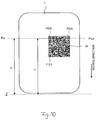
- QR code ® M as illustrated in Fig. 1A is included as the information to be printed on a label (print area).
- the QR code M is configured such that finder patterns (positioning symbols) FD1, FD2, and FD3 are disposed at three corners of a square data area.
- the QR code M having such a structure records data with redundancy, and error correction is made possible when reading the data from the QR code (M). Accordingly, even if a part of the QR code (M) is unclean or damaged and the data is not readable correctly, the data can be restored normally by the error correction.
- the present invention has been made in view of the above situation, and aims to provide a printer capable of printing a QR code on print areas sequentially arranged along a sheet of paper at higher speed while maintaining the QR code always in a state in which its data can be restored.
- a printer is configured as a printer for performing printing to print areas according to print data representing information to be printed while sequentially moving a sheet of paper, along which the print areas are arranged at predetermined intervals, in a direction of the arrangement of the print areas, the printer is provided with: print operation control means for controlling a print operation so as to stop movement of the paper to suspend printing to a print area and then to resume the movement of the paper and the printing to the print area; determination means for determining, if the print data includes data representing a QR code to be printed in a predetermined orientation with respect to the print areas, whether or not both of two finder patterns aligned along one side of the QR code in the print area for which the printing is suspended are at a position to be printed when the movement of the paper is stopped; and print operation correcting control means for controlling the print operation, when the determination means has determined that both of the two finder patterns aligned along one side of the QR code in the print area for which the printing is suspended are at the position to be printed when the movement of the paper is stopped
- the printer according to the present invention may be configured so as to perform printing to labels as the print areas according to the print data, and sequentially separates a label that has been printed from the paper.
- the print operation control means controls the print operation so as to stop the movement of the paper, suspend the printing to the label, cut the paper at the boundary portion to separate the leading label that has been printed from the paper, and then resume the movement of the paper and the printing to the label.
- both of the two finder patterns aligned along one side of the QR code are not actually at the position to be printed at the same time when resuming the printing to the print area (label) for which the printing is suspended. Therefore, even if a white streak appears over a printed portion on the print area (label) due to the suspension and resuming of the movement of the paper and the printing, the white streak may not appear on both of the two finder patterns aligned along one side of the QR code.
- the printer according to the present invention may be configured such that the print operation correcting control means controls the print operation so as to change an orientation of the QR code.
- the printing to the each print area is performed by changing an orientation of the QR code such that both of the two finder patterns aligned along one side of the QR code are not at the position to be printed at the same time. Therefore, even if a white streak appears over the printed portion on the label due to the suspension and resuming of the movement of the paper and the printing, the white streak may not appear on both of the two finder patterns aligned along one side of the QR code.
- the orientation of the QR code it is possible to prevent both of the two finder patterns aligned along one side of the QR code from being at the position to be printed at the same time without changing the print position of the QR code in each print area to a large degree.
- the printer according to the present invention may be configured such that the print operation correcting control means controls the print operation such that the QR code is turned by 90 degrees.
- the printing to the each print area is performed by turning the QR code by 90 degrees such that both of the two finder patterns aligned along one side of the QR code are not at the position to be printed at the same time. Therefore, even if a white streak appears over the printed portion on the print area due to the suspension and resuming of the movement of the paper and the printing, the white streak may not appear on both of the two finder patterns aligned along one side of the QR code.
- by turning the square QR code by 90 degrees it is possible to prevent both of the two finder patterns aligned along one side of the QR code from being at the position to be printed at the same time without changing visual appearance of a print state to a large degree.
- the printer according to the present invention may be configured such that the print operation correcting control means includes print data correction means for correcting the print data so that both of the two finder patterns are not at the position to be printed at the same time.
- the print data is corrected such that both of the two finder patterns aligned along one side of the QR code are not at the position to be printed at the same time. Therefore, when printing to the print areas of the paper moving according to the print data, even if a white streak appears over the printed portion on the print area due to the suspension and resuming of the movement of the paper and the printing, the white streak may not appear on both of the two finder patterns aligned along one side of the QR code.
- a print operation is performed so as to stop movement of a sheet of paper to suspend printing to a print area and then to resume the movement of the paper and the printing to the print area.
- it is possible to perform printing consecutively to the print areas while moving the paper in one direction, without moving in a reverse direction.
- the white streak may not appear on both of the two finder patterns aligned along one side of the QR code. Therefore, it is possible to prevent a situation in which it is not possible to restore data from the QR code printed on the labels from occurring.
- a printer (label printer) according to one embodiment of the present invention is constructed as illustrated in Fig. 2 .
- a sheet of paper S having a liner of a predetermined width and labels (print areas) temporarily attached to the liner at predetermined intervals is rolled into a roll 11, and the paper S paid out from the roll 11 by a pay-out roller 12 moves along a paper transfer path 100.
- This label printer is a thermal-transfer printer, in which a thermal head 23 is disposed at a predetermined position along the paper transfer path 100, and a platen roller 24 is disposed so as to face against the thermal head 23.
- An ink ribbon 20 is suspended between a feed roller 21 and a take-up roller 22, and the ink ribbon 20 sent out from the feed roller 21 is wound up by the take-up roller 22 via a plurality of tension rollers. Further, the ink ribbon 20 and the paper S that moves along the paper transfer path 100 overlapping with each other pass through between the thermal head 23 and the platen roller 24.
- a paper position sensor 13 configured to detect a leading end of the paper S paid out from the roll 11 is provided.
- a cutter 14 configured to cut the paper S is disposed.
- This label printer includes a controller 10 configured to control a print operation. Based on a detection signal from the paper position detecting sensor 13, print data from an upper device 30 such as a personal computer, and information required for printing such as format data (print information), the controller 10 performs control relating to the print operation to each label (print area) of the paper S such as drive control of the thermal head 23 that performs thermal transfer of the ink ribbon 20 to the paper S, feed control of the paper S, and drive control of the cutter 14. Based on the print operation controlled by the controller 10, the information represented by the print data is printed on a predetermined area in labels of the paper S that moves along the paper transfer path 100, and the paper S is cut and the printed label is separated from the paper S.
- the controller 10 performs processing relating to the print operation according to procedures shown in Fig. 3 and Fig. 4 .
- the paper S paid out from the roll 11 by the pay-out roller 12 is set at a position at which its leading end is detected by the paper position sensor 13 as illustrated in Fig. 2 . (initial position).
- the controller 10 obtains print information required for printing such as print data representing information to be printed and format data representing a print format (such as position and shape of a label and the information to be printed), along with a print request, from the upper device 30 (personal computer) (S11), and extract the print data from the print information and sets the print data in a predetermined memory (S12).
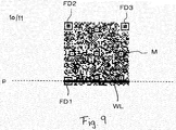
- the controller 10 determines whether or not the print data includes data indicating a QR code to be printed in a predetermined orientation with respect to a label (for example, an orientation in which, as illustrated in Fig. 5 , two finder patterns FD1 and FD2 on one side are aligned on a downmoststream side in a moving direction of the paper S along a direction perpendicular to the moving direction, and two finder patterns FD2 and FD3 on the other side are aligned in parallel to the moving direction of the paper S) (S13) .
- a label for example, an orientation in which, as illustrated in Fig. 5 , two finder patterns FD1 and FD2 on one side are aligned on a downmoststream side in a moving direction of the paper S along a direction perpendicular to the moving direction, and two finder patterns FD2 and FD3 on the other side are aligned in parallel to the moving direction of the paper S
- the controller 10 determines whether or not both of the finder patterns FD1 and FD2 aligned along one side of a QR code M in the label Ln+1 (see Fig.
- a position Pp to be printed (print position: the position at which the thermal head 23 is disposed) when a boundary portion between a printed leading label Ln and a following label Ln+1 reaches a cut position Pc (the position at which the cutter 14 is disposed) as illustrated in Fig. 6 (S14).
- both of the finder patterns FD1 and FD2 aligned along one side of the QR code M in the following label Ln+1 are not at the position Pp1 to be printed when the boundary portion between the printed leading label Ln and the following label Ln+1 reaches the cut position Pc.
- both of the finder patterns FD1 and FD2 aligned along one side of the QR code M in the following label Ln+1 are beyond the position Pp2 when the boundary portion between the printed leading label Ln and the following label Ln+1 reaches the cut position Pc.
- the two finder patterns in the QR code M may not come at the position Pp to be printed at the same time in the following label Ln+1 when the boundary portion between the printed leading label Ln and the following label Ln+1 reaches the cut position Pc, and only the finder pattern FD1 is located at the position Pp to be printed as illustrated in Fig. 8 .
- the set print data is not corrected, if the set print data does not include a QR code (NO in S13), or even when the print data includes a QR code (YES in S13), if not both of the two finder patterns (e.g., FD1 and FD2) aligned along one side of the QR code M in the following label Ln+1 are at position Pp (NO in S14, see Fig. 7 ) when the boundary portion between the printed leading label Ln and the following label Ln+1 reaches the cut position Pc.
- the two finder patterns e.g., FD1 and FD2
- the controller 10 upon setting of the print data (S12) or correction of the set print data (S12-S15), the controller 10 starts transfer control of the paper S whose leading end has been detected by the paper position sensor 13, as illustrated in Fig. 2 (S16). With this, the paper S starts to move along the paper transfer path 100 at a predetermined speed.
- the controller 10 Upon starting of the movement of the paper S, the controller 10 moves to the process shown in Fig. 4 , and monitors whether or not print start timing for the leading label of the paper S has come (S17). Whether or not the print start timing has come is determined based on, for example, whether a position on the label to start printing has reached the print position Pp (the position of the thermal head 23) based on a feed amount of the paper S, the format data (such as a size of the label, and a print-start position within the label), and the like. If it is determined that the print start timing for the leading label of the paper S has come (YES in S17), the controller 10 starts the drive control of the thermal head 23 based on the print data that has been set as described above (S18). With this, information based on the print data (such as letters, marks, or the QR code M) is printed on the leading label of the paper S that is moving.
- the print start timing such as letters, marks, or the QR code M
- the controller 10 While printing on the leading label, the controller 10 monitors whether or not the boundary portion between the leading label and the following label has reached the cut position Pc (S19) and whether or not end printing timing for the leading label has come (S20). Then, when the end printing timing for the leading label comes (YES in S20), the controller 10 stops the drive control of the thermal head 23 to terminate the printing (S21). Thereafter, the controller 10 determines whether or not printing on an instructed number of labels has been completed (S22), and if not (NO in S22), monitors whether or not print start timing for the following label has come (S17) . When the print start timing for the following label has come (YES in S17), the controller 10 starts the drive control of the thermal head 23 based on the print data that has been set as described above (S18), and starts printing on the following label.
- the controller 10 monitors whether or not the boundary portion between the leading label that has been printed and the following label has reached the cut position Pc (S19) and whether or not end printing timing for a next following label has come (S20).
- the controller 10 stops transfer of the paper S and suspends the printing (S23).
- the controller 10 controls the cutter 14 to cut the paper S (S24). With this, the leading label that has been printed is separated from the paper S. Subsequently, the controller 10 resumes transferring the paper S and printing on the following label (S25).
- the controller 10 resumes monitoring whether or not a boundary portion between the label that is being printed and the next following label has reached the cut position Pc (S19) and whether or not end printing timing for the label that is being printed has come (S20). Then, when the end printing timing comes (YES in S20), the controller 10 stops the drive control of the thermal head 23 to terminate the printing (S21). Thereafter, the controller 10 executes the same procedures (S17-S25) repeatedly until the printing on all of the instructed number of labels is completed (S22).
- the controller 10 performs a cutting process for a last printed label (S26). With this process, the paper S moves until the leading label that is to be last printed reaches the cut position Pc without printing on the following label. Then, when the boundary portion between the leading label that has been printed and the following label reaches the cut position Pc, the paper S is cut by the cutter 14, and the last label that has been printed is separated from the paper S.
- the white streaks WL may not appear over both of the two finder patterns FD1 and FD2 aligned along one side of the QR code that is printed on the labels at the same time, it is possible to prevent a situation in which it is not possible to restore data from the QR code M printed on the labels from occurring.
- the method of preventing the two finder patterns FD1 and FD2 from positioning at the print position Pp at the same time is not limited to the above example, and the QR code M may be turned by an angle of any degrees, or may be moved forward, backward, rightward, or leftward.
- the print data includes the data indicating the QR code M to be printed in the orientation in which, as illustrated in Fig. 5 , the two finder patterns FD1 and FD2 on one side are aligned on the downmoststream side in the moving direction of the paper S along the direction perpendicular to the moving direction, and the two finder patterns FD2 and FD3 along the other side are aligned in parallel to the moving direction of the paper S.
- the present invention is not limited to such an example, and it is possible to perform the print operation described above, for example, in a case where the print data includes the data indicating the QR code M to be printed in an orientation in which, as illustrated in Fig.
- the two finder patterns FD2 and FD3 on one side are aligned on a uppermoststream side in the moving direction of the paper S along the direction perpendicular to the moving direction, and the two finder patterns FD1 and FD2 along the other side are aligned parallel to the moving direction of the paper S.
- the QR code M may be turned to the left by 90 degrees when the distance X between the cut position Pc and the print position Pp, the distance Y from the leading end of the paper S (the cut position Pc of the paper S) to the two finder patterns FD2 and FD3, and the width Z of the finder patterns FD2 and FD3 satisfy the previously described condition, that is Y ⁇ X ⁇ Y+Z (see the situation illustrated in Fig. 7 ).
- the printing on the following label Ln+1 is performed when the boundary portion between the printed leading label Ln and the following label Ln+1 reaches the cut position Pc as illustrated in Fig. 6 .
- the arrangement and pitches of the labels on the paper S and the position of the cutter 14 there is a case in which printing on a label on an upperstream side of the following label Ln+1 is performed when the boundary portion between the printed leading label Ln and the following label Ln+1 reaches the cut position Pc.
- the print operation is controlled so as to stop the movement of the paper S and suspend the printing on the label Ln+1, as illustrated in Fig. 6 , when the boundary portion between the printed leading label Ln and the following label Ln+1 reaches the cut position Pc, to cut the paper at the boundary portion to separate the printed leading label Ln from the paper, and then to resume the movement of the paper S and the printing on the label Ln.
- the print operation may not be particularly limited to this as long as the movement of the paper is stopped for some reason to suspend printing on the label, and then the movement of the paper and the printing on the label are resumed.
- the print operation may be controlled such that the movement of the paper S is stopped and the printing on the label Ln+1 is suspended when the printed leading label Ln reaches the separation position, the printed label Ln is separated from the liner and applied to a predetermined object, and then the movement of the paper S and the printing on the label Ln are resumed.
- a sheet of strip-shaped paper on which tags having holes at regular intervals are provided as the print areas, or a sheet of paper having labels without a liner arranged thereon as the print areas may be employed.
- the label printer according to the present invention is not limited to a thermal printer, and may be a printer of a different type.
- the label printer according to the present invention provides an effect of enabling printing of a QR code on labels sequentially arranged along a sheet of paper at higher speed while maintaining the QR code always in a state in which its data can be restored, and useful as a label printer configured such that in the process of movement of a sheet of paper having liner and labels temporarily attached to the liner at regular intervals moves, a printed label is separated from the paper while performing printing to the labels.
Landscapes
- Engineering & Computer Science (AREA)
- Physics & Mathematics (AREA)
- General Physics & Mathematics (AREA)
- Theoretical Computer Science (AREA)
- General Engineering & Computer Science (AREA)
- Record Information Processing For Printing (AREA)
- Printers Characterized By Their Purpose (AREA)
- Accessory Devices And Overall Control Thereof (AREA)
- Handling Of Sheets (AREA)
Applications Claiming Priority (2)
| Application Number | Priority Date | Filing Date | Title |
|---|---|---|---|
| JP2011088975A JP5657461B2 (ja) | 2011-04-13 | 2011-04-13 | プリンタ |
| PCT/JP2012/002595 WO2012140914A1 (ja) | 2011-04-13 | 2012-04-13 | プリンタ |
Publications (3)
| Publication Number | Publication Date |
|---|---|
| EP2698257A1 EP2698257A1 (en) | 2014-02-19 |
| EP2698257A4 EP2698257A4 (en) | 2014-10-01 |
| EP2698257B1 true EP2698257B1 (en) | 2016-03-02 |
Family
ID=47009103
Family Applications (1)
| Application Number | Title | Priority Date | Filing Date |
|---|---|---|---|
| EP12771561.3A Not-in-force EP2698257B1 (en) | 2011-04-13 | 2012-04-13 | Printer |
Country Status (4)
| Country | Link |
|---|---|
| US (1) | US8947725B2 (enExample) |
| EP (1) | EP2698257B1 (enExample) |
| JP (1) | JP5657461B2 (enExample) |
| WO (1) | WO2012140914A1 (enExample) |
Families Citing this family (9)
| Publication number | Priority date | Publication date | Assignee | Title |
|---|---|---|---|---|
| EP3011790B1 (en) * | 2013-06-19 | 2018-01-10 | Telefonaktiebolaget LM Ericsson (publ) | Methods and devices for controlling antenna points |
| JP6111896B2 (ja) * | 2013-06-27 | 2017-04-12 | セイコーエプソン株式会社 | 媒体処理システム、印刷システム、媒体処理システムの制御方法、及び、媒体処理装置 |
| JP2016001396A (ja) * | 2014-06-11 | 2016-01-07 | 富士ゼロックス株式会社 | 画像処理装置、システム及びプログラム |
| JP6453119B2 (ja) * | 2015-03-16 | 2019-01-16 | 株式会社沖データ | 画像形成装置、及び画像形成装置の制御方法 |
| CN106240165B (zh) * | 2015-06-03 | 2018-03-09 | 精工爱普生株式会社 | 标签制作装置以及标签制作方法 |
| WO2018193151A1 (en) * | 2017-04-18 | 2018-10-25 | Upm Raflatac Oy | A method for selecting a face material for a printable label and a printed label |
| CN107870751A (zh) * | 2017-11-17 | 2018-04-03 | 珠海恒全条码设备有限公司 | 一种控件编辑方法及系统 |
| JP7225914B2 (ja) * | 2019-02-28 | 2023-02-21 | ブラザー工業株式会社 | 画像形成装置 |
| JP7275656B2 (ja) * | 2019-02-28 | 2023-05-18 | ブラザー工業株式会社 | 液体吐出装置及びプログラム |
Family Cites Families (18)
| Publication number | Priority date | Publication date | Assignee | Title |
|---|---|---|---|---|
| JPH0753458B2 (ja) * | 1987-06-30 | 1995-06-07 | 株式会社テック | ラベルプリンタ |
| US5025397A (en) * | 1988-08-24 | 1991-06-18 | Tokyo Electric Co., Ltd. | Label printer |
| JP2537553B2 (ja) * | 1989-10-13 | 1996-09-25 | 株式会社テック | サ―マルプリンタ |
| US5248993A (en) * | 1990-09-07 | 1993-09-28 | Tohoku Ricoh Co., Ltd. | Thermal printer having a controller for controlling paper feed operation and a printing method thereof |
| EP0574657B1 (en) * | 1992-03-11 | 2000-11-15 | Chinon Industries Inc. | Label printing apparatus and wordprocessor |
| JP3691618B2 (ja) | 1996-04-15 | 2005-09-07 | セイコーエプソン株式会社 | テープ印刷装置 |
| US6535299B1 (en) * | 1999-09-14 | 2003-03-18 | Printronix, Inc. | Bar code verification and printing system |
| JP4443760B2 (ja) * | 2000-12-18 | 2010-03-31 | 株式会社サトー | ラベルプリンタ及びそのカット処理方法 |
| US6672510B2 (en) * | 2001-12-20 | 2004-01-06 | Scannabar (3193519 Canada Inc.) | Bar code arrangement for identifying positions along an axis |
| JP2004160981A (ja) | 2002-09-20 | 2004-06-10 | Tohoku Ricoh Co Ltd | 標印印刷・検証装置およびその印刷標印検証方法と標印印刷制御方法 |
| US7181066B1 (en) * | 2002-12-26 | 2007-02-20 | Cognex Technology And Investment Corporation | Method for locating bar codes and symbols in an image |
| JP4364615B2 (ja) * | 2003-11-28 | 2009-11-18 | 横浜ゴム株式会社 | 2次元コード表示物及び2次元コード表示タイヤ |
| JP4569382B2 (ja) * | 2005-05-20 | 2010-10-27 | ブラザー工業株式会社 | 印刷データ編集装置、印刷データ編集プログラム及び記録媒体 |
| JP4483727B2 (ja) * | 2005-07-15 | 2010-06-16 | セイコーエプソン株式会社 | 印刷画像作成装置、印刷画像作成方法およびプログラム |
| KR100828539B1 (ko) * | 2005-09-20 | 2008-05-13 | 후지제롯쿠스 가부시끼가이샤 | 이차원 코드의 검출 방법, 검출 장치, 및 검출 프로그램을기억한 기억 매체 |
| US7692812B2 (en) * | 2006-01-20 | 2010-04-06 | Lexmark International, Inc. | System, method and apparatus for registration of printed image to media orientation |
| JP2007323498A (ja) * | 2006-06-02 | 2007-12-13 | Daido Steel Co Ltd | 情報コード表示シート |
| US7988037B2 (en) * | 2009-11-02 | 2011-08-02 | Research In Motion Limited | Device and method for contact information exchange |
-
2011
- 2011-04-13 JP JP2011088975A patent/JP5657461B2/ja active Active
-
2012
- 2012-04-13 WO PCT/JP2012/002595 patent/WO2012140914A1/ja not_active Ceased
- 2012-04-13 US US14/111,204 patent/US8947725B2/en active Active
- 2012-04-13 EP EP12771561.3A patent/EP2698257B1/en not_active Not-in-force
Also Published As
| Publication number | Publication date |
|---|---|
| EP2698257A4 (en) | 2014-10-01 |
| JP5657461B2 (ja) | 2015-01-21 |
| US20140036280A1 (en) | 2014-02-06 |
| US8947725B2 (en) | 2015-02-03 |
| WO2012140914A1 (ja) | 2012-10-18 |
| JP2012218385A (ja) | 2012-11-12 |
| EP2698257A1 (en) | 2014-02-19 |
Similar Documents
| Publication | Publication Date | Title |
|---|---|---|
| EP2698257B1 (en) | Printer | |
| EP2141023B1 (en) | Printer | |
| US8371672B2 (en) | Printing apparatus and method for duplex printing | |
| US10328728B2 (en) | Image recording apparatus and image recording method for printing each of a plurality of unit images | |
| EP3299175B1 (en) | Printer, and printer control method | |
| RU2598289C2 (ru) | Печатующее устройство, способ управления и запоминающий носитель | |
| JP2009226716A (ja) | 画像形成装置、切断装置、画像形成システム、画像形成プログラム、及び切断プログラム | |
| US9757958B2 (en) | Control method of a printing device, and printing device | |
| JP7259672B2 (ja) | 画像形成装置及び画像形成方法 | |
| US20210039404A1 (en) | Printer | |
| JP2004082348A (ja) | 記録装置 | |
| US9033601B2 (en) | Recording device, control method of a recording device, and storage medium | |
| JP2019022945A (ja) | 画像記録装置、情報処理装置、画像記録システム、および画像作成方法 | |
| JP2014015006A (ja) | ラベルプリンタ | |
| JP4494040B2 (ja) | ラベルプリンターの印字制御方法 | |
| JP2004058337A (ja) | 印刷装置 | |
| JP2019005913A (ja) | 記録装置および記録制御方法 | |
| JP5708223B2 (ja) | タイミングマークの印刷方法及び連続帳票加工装置 | |
| JP6092050B2 (ja) | ラベルプリンターのラベル検出装置およびラベル検出方法 | |
| US8905510B2 (en) | Printer | |
| JP7314923B2 (ja) | 印刷装置、制御方法、及びプログラム | |
| JP2019064240A (ja) | 画像記録装置および記録方法 | |
| JP4838656B2 (ja) | 熱転写プリンタ | |
| JP4343731B2 (ja) | 画像形成装置 | |
| JP4473682B2 (ja) | 印字装置 |
Legal Events
| Date | Code | Title | Description |
|---|---|---|---|
| PUAI | Public reference made under article 153(3) epc to a published international application that has entered the european phase |
Free format text: ORIGINAL CODE: 0009012 |
|
| 17P | Request for examination filed |
Effective date: 20131010 |
|
| AK | Designated contracting states |
Kind code of ref document: A1 Designated state(s): AL AT BE BG CH CY CZ DE DK EE ES FI FR GB GR HR HU IE IS IT LI LT LU LV MC MK MT NL NO PL PT RO RS SE SI SK SM TR |
|
| DAX | Request for extension of the european patent (deleted) | ||
| A4 | Supplementary search report drawn up and despatched |
Effective date: 20140903 |
|
| RIC1 | Information provided on ipc code assigned before grant |
Ipc: B41J 3/01 20060101AFI20140828BHEP Ipc: B41J 21/00 20060101ALI20140828BHEP Ipc: B41J 29/38 20060101ALI20140828BHEP |
|
| GRAJ | Information related to disapproval of communication of intention to grant by the applicant or resumption of examination proceedings by the epo deleted |
Free format text: ORIGINAL CODE: EPIDOSDIGR1 |
|
| GRAP | Despatch of communication of intention to grant a patent |
Free format text: ORIGINAL CODE: EPIDOSNIGR1 |
|
| GRAP | Despatch of communication of intention to grant a patent |
Free format text: ORIGINAL CODE: EPIDOSNIGR1 |
|
| INTG | Intention to grant announced |
Effective date: 20150819 |
|
| INTC | Intention to grant announced (deleted) | ||
| INTG | Intention to grant announced |
Effective date: 20150901 |
|
| GRAS | Grant fee paid |
Free format text: ORIGINAL CODE: EPIDOSNIGR3 |
|
| GRAA | (expected) grant |
Free format text: ORIGINAL CODE: 0009210 |
|
| AK | Designated contracting states |
Kind code of ref document: B1 Designated state(s): AL AT BE BG CH CY CZ DE DK EE ES FI FR GB GR HR HU IE IS IT LI LT LU LV MC MK MT NL NO PL PT RO RS SE SI SK SM TR |
|
| REG | Reference to a national code |
Ref country code: GB Ref legal event code: FG4D |
|
| REG | Reference to a national code |
Ref country code: AT Ref legal event code: REF Ref document number: 777729 Country of ref document: AT Kind code of ref document: T Effective date: 20160315 Ref country code: CH Ref legal event code: EP |
|
| REG | Reference to a national code |
Ref country code: IE Ref legal event code: FG4D |
|
| REG | Reference to a national code |
Ref country code: DE Ref legal event code: R096 Ref document number: 602012015256 Country of ref document: DE |
|
| REG | Reference to a national code |
Ref country code: FR Ref legal event code: PLFP Year of fee payment: 5 |
|
| REG | Reference to a national code |
Ref country code: NL Ref legal event code: MP Effective date: 20160302 |
|
| REG | Reference to a national code |
Ref country code: LT Ref legal event code: MG4D |
|
| REG | Reference to a national code |
Ref country code: AT Ref legal event code: MK05 Ref document number: 777729 Country of ref document: AT Kind code of ref document: T Effective date: 20160302 |
|
| PG25 | Lapsed in a contracting state [announced via postgrant information from national office to epo] |
Ref country code: GR Free format text: LAPSE BECAUSE OF FAILURE TO SUBMIT A TRANSLATION OF THE DESCRIPTION OR TO PAY THE FEE WITHIN THE PRESCRIBED TIME-LIMIT Effective date: 20160603 Ref country code: ES Free format text: LAPSE BECAUSE OF FAILURE TO SUBMIT A TRANSLATION OF THE DESCRIPTION OR TO PAY THE FEE WITHIN THE PRESCRIBED TIME-LIMIT Effective date: 20160302 Ref country code: HR Free format text: LAPSE BECAUSE OF FAILURE TO SUBMIT A TRANSLATION OF THE DESCRIPTION OR TO PAY THE FEE WITHIN THE PRESCRIBED TIME-LIMIT Effective date: 20160302 Ref country code: NO Free format text: LAPSE BECAUSE OF FAILURE TO SUBMIT A TRANSLATION OF THE DESCRIPTION OR TO PAY THE FEE WITHIN THE PRESCRIBED TIME-LIMIT Effective date: 20160602 Ref country code: FI Free format text: LAPSE BECAUSE OF FAILURE TO SUBMIT A TRANSLATION OF THE DESCRIPTION OR TO PAY THE FEE WITHIN THE PRESCRIBED TIME-LIMIT Effective date: 20160302 |
|
| PG25 | Lapsed in a contracting state [announced via postgrant information from national office to epo] |
Ref country code: BE Free format text: LAPSE BECAUSE OF NON-PAYMENT OF DUE FEES Effective date: 20160430 Ref country code: RS Free format text: LAPSE BECAUSE OF FAILURE TO SUBMIT A TRANSLATION OF THE DESCRIPTION OR TO PAY THE FEE WITHIN THE PRESCRIBED TIME-LIMIT Effective date: 20160302 Ref country code: LV Free format text: LAPSE BECAUSE OF FAILURE TO SUBMIT A TRANSLATION OF THE DESCRIPTION OR TO PAY THE FEE WITHIN THE PRESCRIBED TIME-LIMIT Effective date: 20160302 Ref country code: NL Free format text: LAPSE BECAUSE OF FAILURE TO SUBMIT A TRANSLATION OF THE DESCRIPTION OR TO PAY THE FEE WITHIN THE PRESCRIBED TIME-LIMIT Effective date: 20160302 Ref country code: AT Free format text: LAPSE BECAUSE OF FAILURE TO SUBMIT A TRANSLATION OF THE DESCRIPTION OR TO PAY THE FEE WITHIN THE PRESCRIBED TIME-LIMIT Effective date: 20160302 Ref country code: PL Free format text: LAPSE BECAUSE OF FAILURE TO SUBMIT A TRANSLATION OF THE DESCRIPTION OR TO PAY THE FEE WITHIN THE PRESCRIBED TIME-LIMIT Effective date: 20160302 Ref country code: SE Free format text: LAPSE BECAUSE OF FAILURE TO SUBMIT A TRANSLATION OF THE DESCRIPTION OR TO PAY THE FEE WITHIN THE PRESCRIBED TIME-LIMIT Effective date: 20160302 Ref country code: LT Free format text: LAPSE BECAUSE OF FAILURE TO SUBMIT A TRANSLATION OF THE DESCRIPTION OR TO PAY THE FEE WITHIN THE PRESCRIBED TIME-LIMIT Effective date: 20160302 |
|
| PG25 | Lapsed in a contracting state [announced via postgrant information from national office to epo] |
Ref country code: IS Free format text: LAPSE BECAUSE OF FAILURE TO SUBMIT A TRANSLATION OF THE DESCRIPTION OR TO PAY THE FEE WITHIN THE PRESCRIBED TIME-LIMIT Effective date: 20160702 Ref country code: EE Free format text: LAPSE BECAUSE OF FAILURE TO SUBMIT A TRANSLATION OF THE DESCRIPTION OR TO PAY THE FEE WITHIN THE PRESCRIBED TIME-LIMIT Effective date: 20160302 |
|
| PG25 | Lapsed in a contracting state [announced via postgrant information from national office to epo] |
Ref country code: SM Free format text: LAPSE BECAUSE OF FAILURE TO SUBMIT A TRANSLATION OF THE DESCRIPTION OR TO PAY THE FEE WITHIN THE PRESCRIBED TIME-LIMIT Effective date: 20160302 Ref country code: CZ Free format text: LAPSE BECAUSE OF FAILURE TO SUBMIT A TRANSLATION OF THE DESCRIPTION OR TO PAY THE FEE WITHIN THE PRESCRIBED TIME-LIMIT Effective date: 20160302 Ref country code: RO Free format text: LAPSE BECAUSE OF FAILURE TO SUBMIT A TRANSLATION OF THE DESCRIPTION OR TO PAY THE FEE WITHIN THE PRESCRIBED TIME-LIMIT Effective date: 20160302 Ref country code: SK Free format text: LAPSE BECAUSE OF FAILURE TO SUBMIT A TRANSLATION OF THE DESCRIPTION OR TO PAY THE FEE WITHIN THE PRESCRIBED TIME-LIMIT Effective date: 20160302 Ref country code: PT Free format text: LAPSE BECAUSE OF FAILURE TO SUBMIT A TRANSLATION OF THE DESCRIPTION OR TO PAY THE FEE WITHIN THE PRESCRIBED TIME-LIMIT Effective date: 20160704 |
|
| REG | Reference to a national code |
Ref country code: CH Ref legal event code: PL |
|
| REG | Reference to a national code |
Ref country code: DE Ref legal event code: R097 Ref document number: 602012015256 Country of ref document: DE |
|
| PG25 | Lapsed in a contracting state [announced via postgrant information from national office to epo] |
Ref country code: BE Free format text: LAPSE BECAUSE OF FAILURE TO SUBMIT A TRANSLATION OF THE DESCRIPTION OR TO PAY THE FEE WITHIN THE PRESCRIBED TIME-LIMIT Effective date: 20160302 Ref country code: IT Free format text: LAPSE BECAUSE OF FAILURE TO SUBMIT A TRANSLATION OF THE DESCRIPTION OR TO PAY THE FEE WITHIN THE PRESCRIBED TIME-LIMIT Effective date: 20160302 |
|
| PLBE | No opposition filed within time limit |
Free format text: ORIGINAL CODE: 0009261 |
|
| STAA | Information on the status of an ep patent application or granted ep patent |
Free format text: STATUS: NO OPPOSITION FILED WITHIN TIME LIMIT |
|
| REG | Reference to a national code |
Ref country code: IE Ref legal event code: MM4A |
|
| PG25 | Lapsed in a contracting state [announced via postgrant information from national office to epo] |
Ref country code: DK Free format text: LAPSE BECAUSE OF FAILURE TO SUBMIT A TRANSLATION OF THE DESCRIPTION OR TO PAY THE FEE WITHIN THE PRESCRIBED TIME-LIMIT Effective date: 20160302 Ref country code: CH Free format text: LAPSE BECAUSE OF NON-PAYMENT OF DUE FEES Effective date: 20160430 Ref country code: LI Free format text: LAPSE BECAUSE OF NON-PAYMENT OF DUE FEES Effective date: 20160430 |
|
| 26N | No opposition filed |
Effective date: 20161205 |
|
| PG25 | Lapsed in a contracting state [announced via postgrant information from national office to epo] |
Ref country code: SI Free format text: LAPSE BECAUSE OF FAILURE TO SUBMIT A TRANSLATION OF THE DESCRIPTION OR TO PAY THE FEE WITHIN THE PRESCRIBED TIME-LIMIT Effective date: 20160302 Ref country code: BG Free format text: LAPSE BECAUSE OF FAILURE TO SUBMIT A TRANSLATION OF THE DESCRIPTION OR TO PAY THE FEE WITHIN THE PRESCRIBED TIME-LIMIT Effective date: 20160602 |
|
| REG | Reference to a national code |
Ref country code: FR Ref legal event code: PLFP Year of fee payment: 6 |
|
| PG25 | Lapsed in a contracting state [announced via postgrant information from national office to epo] |
Ref country code: IE Free format text: LAPSE BECAUSE OF NON-PAYMENT OF DUE FEES Effective date: 20160413 |
|
| REG | Reference to a national code |
Ref country code: FR Ref legal event code: PLFP Year of fee payment: 7 |
|
| PG25 | Lapsed in a contracting state [announced via postgrant information from national office to epo] |
Ref country code: HU Free format text: LAPSE BECAUSE OF FAILURE TO SUBMIT A TRANSLATION OF THE DESCRIPTION OR TO PAY THE FEE WITHIN THE PRESCRIBED TIME-LIMIT; INVALID AB INITIO Effective date: 20120413 Ref country code: CY Free format text: LAPSE BECAUSE OF FAILURE TO SUBMIT A TRANSLATION OF THE DESCRIPTION OR TO PAY THE FEE WITHIN THE PRESCRIBED TIME-LIMIT Effective date: 20160302 |
|
| PG25 | Lapsed in a contracting state [announced via postgrant information from national office to epo] |
Ref country code: MK Free format text: LAPSE BECAUSE OF FAILURE TO SUBMIT A TRANSLATION OF THE DESCRIPTION OR TO PAY THE FEE WITHIN THE PRESCRIBED TIME-LIMIT Effective date: 20160302 Ref country code: TR Free format text: LAPSE BECAUSE OF FAILURE TO SUBMIT A TRANSLATION OF THE DESCRIPTION OR TO PAY THE FEE WITHIN THE PRESCRIBED TIME-LIMIT Effective date: 20160302 Ref country code: MT Free format text: LAPSE BECAUSE OF NON-PAYMENT OF DUE FEES Effective date: 20160430 Ref country code: MC Free format text: LAPSE BECAUSE OF FAILURE TO SUBMIT A TRANSLATION OF THE DESCRIPTION OR TO PAY THE FEE WITHIN THE PRESCRIBED TIME-LIMIT Effective date: 20160302 Ref country code: LU Free format text: LAPSE BECAUSE OF NON-PAYMENT OF DUE FEES Effective date: 20160413 |
|
| PG25 | Lapsed in a contracting state [announced via postgrant information from national office to epo] |
Ref country code: AL Free format text: LAPSE BECAUSE OF FAILURE TO SUBMIT A TRANSLATION OF THE DESCRIPTION OR TO PAY THE FEE WITHIN THE PRESCRIBED TIME-LIMIT Effective date: 20160302 |
|
| P01 | Opt-out of the competence of the unified patent court (upc) registered |
Effective date: 20230411 |
|
| PGFP | Annual fee paid to national office [announced via postgrant information from national office to epo] |
Ref country code: GB Payment date: 20240419 Year of fee payment: 13 |
|
| PGFP | Annual fee paid to national office [announced via postgrant information from national office to epo] |
Ref country code: DE Payment date: 20240418 Year of fee payment: 13 |
|
| PGFP | Annual fee paid to national office [announced via postgrant information from national office to epo] |
Ref country code: FR Payment date: 20240425 Year of fee payment: 13 |
|
| REG | Reference to a national code |
Ref country code: DE Ref legal event code: R119 Ref document number: 602012015256 Country of ref document: DE |
|
| GBPC | Gb: european patent ceased through non-payment of renewal fee |
Effective date: 20250413 |
|
| PG25 | Lapsed in a contracting state [announced via postgrant information from national office to epo] |
Ref country code: DE Free format text: LAPSE BECAUSE OF NON-PAYMENT OF DUE FEES Effective date: 20251104 |
|
| PG25 | Lapsed in a contracting state [announced via postgrant information from national office to epo] |
Ref country code: GB Free format text: LAPSE BECAUSE OF NON-PAYMENT OF DUE FEES Effective date: 20250413 |
|
| PG25 | Lapsed in a contracting state [announced via postgrant information from national office to epo] |
Ref country code: FR Free format text: LAPSE BECAUSE OF NON-PAYMENT OF DUE FEES Effective date: 20250430 |