WO2012140914A1 - プリンタ - Google Patents
プリンタ Download PDFInfo
- Publication number
- WO2012140914A1 WO2012140914A1 PCT/JP2012/002595 JP2012002595W WO2012140914A1 WO 2012140914 A1 WO2012140914 A1 WO 2012140914A1 JP 2012002595 W JP2012002595 W JP 2012002595W WO 2012140914 A1 WO2012140914 A1 WO 2012140914A1
- Authority
- WO
- WIPO (PCT)
- Prior art keywords
- label
- printed
- printing
- paper
- Prior art date
- Legal status (The legal status is an assumption and is not a legal conclusion. Google has not performed a legal analysis and makes no representation as to the accuracy of the status listed.)
- Ceased
Links
Images


Classifications
-
- G—PHYSICS
- G06—COMPUTING OR CALCULATING; COUNTING
- G06K—GRAPHICAL DATA READING; PRESENTATION OF DATA; RECORD CARRIERS; HANDLING RECORD CARRIERS
- G06K15/00—Arrangements for producing a permanent visual presentation of the output data, e.g. computer output printers
- G06K15/02—Arrangements for producing a permanent visual presentation of the output data, e.g. computer output printers using printers
- G06K15/18—Conditioning data for presenting it to the physical printing elements
- G06K15/1867—Post-processing of the composed and rasterized print image
-
- B—PERFORMING OPERATIONS; TRANSPORTING
- B41—PRINTING; LINING MACHINES; TYPEWRITERS; STAMPS
- B41J—TYPEWRITERS; SELECTIVE PRINTING MECHANISMS, i.e. MECHANISMS PRINTING OTHERWISE THAN FROM A FORME; CORRECTION OF TYPOGRAPHICAL ERRORS
- B41J3/00—Typewriters or selective printing or marking mechanisms characterised by the purpose for which they are constructed
- B41J3/01—Typewriters or selective printing or marking mechanisms characterised by the purpose for which they are constructed for special character, e.g. for Chinese characters or barcodes
-
- B—PERFORMING OPERATIONS; TRANSPORTING
- B41—PRINTING; LINING MACHINES; TYPEWRITERS; STAMPS
- B41J—TYPEWRITERS; SELECTIVE PRINTING MECHANISMS, i.e. MECHANISMS PRINTING OTHERWISE THAN FROM A FORME; CORRECTION OF TYPOGRAPHICAL ERRORS
- B41J11/00—Devices or arrangements of selective printing mechanisms, e.g. ink-jet printers or thermal printers, for supporting or handling copy material in sheet or web form
- B41J11/36—Blanking or long feeds; Feeding to a particular line, e.g. by rotation of platen or feed roller
- B41J11/42—Controlling printing material conveyance for accurate alignment of the printing material with the printhead; Print registering
-
- B—PERFORMING OPERATIONS; TRANSPORTING
- B41—PRINTING; LINING MACHINES; TYPEWRITERS; STAMPS
- B41J—TYPEWRITERS; SELECTIVE PRINTING MECHANISMS, i.e. MECHANISMS PRINTING OTHERWISE THAN FROM A FORME; CORRECTION OF TYPOGRAPHICAL ERRORS
- B41J3/00—Typewriters or selective printing or marking mechanisms characterised by the purpose for which they are constructed
- B41J3/407—Typewriters or selective printing or marking mechanisms characterised by the purpose for which they are constructed for marking on special material
- B41J3/4075—Tape printers; Label printers
-
- G—PHYSICS
- G06—COMPUTING OR CALCULATING; COUNTING
- G06K—GRAPHICAL DATA READING; PRESENTATION OF DATA; RECORD CARRIERS; HANDLING RECORD CARRIERS
- G06K1/00—Methods or arrangements for marking the record carrier in digital fashion
- G06K1/12—Methods or arrangements for marking the record carrier in digital fashion otherwise than by punching
- G06K1/121—Methods or arrangements for marking the record carrier in digital fashion otherwise than by punching by printing code marks
-
- G—PHYSICS
- G06—COMPUTING OR CALCULATING; COUNTING
- G06K—GRAPHICAL DATA READING; PRESENTATION OF DATA; RECORD CARRIERS; HANDLING RECORD CARRIERS
- G06K15/00—Arrangements for producing a permanent visual presentation of the output data, e.g. computer output printers
- G06K15/02—Arrangements for producing a permanent visual presentation of the output data, e.g. computer output printers using printers
- G06K15/021—Adaptations for printing on specific media
- G06K15/024—Adaptations for printing on specific media for printing on segmented surfaces, e.g. sticker sheets, label rolls
-
- G—PHYSICS
- G06—COMPUTING OR CALCULATING; COUNTING
- G06K—GRAPHICAL DATA READING; PRESENTATION OF DATA; RECORD CARRIERS; HANDLING RECORD CARRIERS
- G06K15/00—Arrangements for producing a permanent visual presentation of the output data, e.g. computer output printers
- G06K15/02—Arrangements for producing a permanent visual presentation of the output data, e.g. computer output printers using printers
- G06K15/16—Means for paper feeding or form feeding
-
- G—PHYSICS
- G06—COMPUTING OR CALCULATING; COUNTING
- G06K—GRAPHICAL DATA READING; PRESENTATION OF DATA; RECORD CARRIERS; HANDLING RECORD CARRIERS
- G06K5/00—Methods or arrangements for verifying the correctness of markings on a record carrier; Column detection devices
Definitions
- the present invention relates to a label printer or the like in which a printed label is cut out from a sheet while printing is performed on each label in a process in which the sheet temporarily attached to the mount is moved at equal intervals.
- the present invention relates to a printer that prints in each print area while a sheet in which areas are arranged at equal intervals moves a sheet sequentially in the arrangement direction of the print area.
- a label printer described in Patent Document 1 is known.
- a print head (specifically, a thermal head) prints characters according to print data for each label that passes through the print position in the process of moving the paper on which the labels are temporarily attached to the mount. And print marks and marks.
- the first printed label and the next label are printed.
- the boundary portion reaches the cut position, the paper is stopped and printing for the next label is interrupted, the boundary portion of the paper is cut, and the first printed label is cut out. Thereafter, the feeding of the paper is resumed, and the printing for the label on which printing has been suspended is resumed.
- the paper movement continues without printing the next label that passes the print position.
- the sheet is stopped, the boundary of the sheet is cut, and the first printed label is cut out. Thereafter, the sheet is moved (retracted) in the reverse direction so that the leading end of the next label (new leading label) is at the printing position. Then, the next label is printed again while moving the paper in the normal direction. Thereafter, similarly, printing for each label is performed while repeating printing on the label, cutting the paper, and moving the paper in the reverse direction.
- the information to be printed includes a barcode, as described above, when printing for the label is completed, the paper is moved to the cutting position without printing for the next label, and the paper is cut. Later, the paper is returned and the next label is printed. In this manner, since printing is not performed on the next label until each printed label is cut out from the sheet, it is possible to reliably prevent white spots in the barcode.
- the paper when the information to be printed does not include a barcode, the paper can be printed at a higher speed without moving in the reverse direction, and the information to be printed. If the barcode is included in the information, the information can be printed surely.
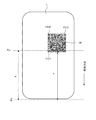
- QR code M as shown in FIG. 1A is included as information to be printed on the label (print area).
- the QR code M has a structure in which finder patterns (cutout symbols) FD1, FD2, and FD3 are arranged at three corners of a square data area. Data is recorded on the QR code M having such a structure with redundancy, and error correction is possible when data is read from the QR code (M). Therefore, even when a part of the QR code (M) is contaminated or damaged and accurate data cannot be read out, normal data can be restored by error correction.
- the QR code M can be restored even if it is partially dirty or damaged (white). Therefore, when the QR code M is printed on each label, the above-described barcode is printed. In this way, the printing for the label is completed, the label is cut out from the paper, the paper is not returned, and the printing for the next label is not performed. Can be cut. Accordingly, it is possible to perform label printing at a higher speed.
- the QR code M may not be able to be restored if the two finder patterns FD1 and FD2 have white spots WL at the same time. For this reason, as described above, if the paper is always cut sequentially while repeatedly feeding and interrupting and resuming printing, data may not be restored from the printed QR code.
- the present invention has been made in view of such circumstances, and a printer capable of printing a QR code at a higher speed in a state in which data can always be restored to each print area sequentially arranged on a sheet. It is to provide.
- the printer according to the present invention is a printer that performs printing on each print area in accordance with print data representing information to be printed while sequentially moving paper in which print areas are arranged at predetermined intervals in the arrangement direction of the print area.
- Printing operation control means for controlling the printing operation so as to stop the movement of the paper to interrupt the printing on the print area and then resume the movement of the paper and the printing on the printing area; and the print data
- both of the two finder patterns arranged on one side of the QR code in the print area where the print is interrupted are both When the paper movement is stopped,
- the determination means for determining whether or not both of the two finder patterns arranged on one side of the QR code in the print area where the printing is interrupted are printed by the determination means when the movement of the paper is stopped.
- a print operation correction control means for controlling the print operation so that both of the two finder patterns of the QR code do not become the positions to be printed at the same time. . *
- the printer according to the present invention can be configured to perform printing on each label as a print area in accordance with the print data, and to sequentially cut out printed labels from the paper.
- the printing operation control means stops the movement of the paper when the boundary between the first printed label and the next label reaches the cut position, and interrupts printing on the label, The border is cut and the first printed label is cut out from the paper, and then the printing operation is controlled so as to resume the movement of the paper and the printing on the label.
- the printing operation correction control means can control the printing operation so as to change the direction of the QR code.
- the direction of the QR code is changed so that both of the two finder patterns arranged on one side of the QR code are not at the same position to be printed, and printing is performed on each print area. Even if a white spot occurs in the print portion of the label due to the movement of the image and the interruption or resumption of printing, the white spot does not affect both of the two finder patterns arranged on one side of the QR code. In particular, by changing the direction of the QR code, both the two finder patterns arranged on one side of the QR code do not have to be printed at the same time without largely changing the print position of the QR code in each print area. can do. *
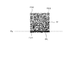
- the printing operation correction control unit may control the printing operation so that the QR code is rotated by 90 °.
- the QR code is printed on each print area while being rotated by 90 ° so that both of the two finder patterns arranged on one side of the QR code are not at positions to be printed at the same time. Even if white spots occur in the print portion of the print area due to the movement of the paper and the interruption or resumption of printing, the white spots do not affect both of the two finder patterns arranged on one side of the QR code. In particular, by rotating the QR code having a square shape by 90 °, both the two finder patterns arranged on one side of the QR code do not become positions to be printed at the same time without largely changing the apparent print state. can do. *
- the print operation correction control means includes a print data correction means for correcting the print data so that both of the two finder patterns are not at positions to be printed simultaneously. can do.
- the print data is corrected so that both of the two finder patterns arranged on one side of the QR code are not at the positions to be printed at the same time.
- the two viewfinders where the white spots are arranged on one side of the QR code. It doesn't affect both patterns.
- the printing operation is performed so as to stop the movement of the paper and interrupt the printing on the print area, and then resume the movement of the paper and the printing on the printing area.
- Each print area can be continuously printed while being moved in one direction without being moved in the reverse direction.
- the white spots do not affect both of the two finder patterns arranged on one side of the QR code. Therefore, it is possible to prevent a situation where data cannot be restored from the QR code printed on each label. Therefore, the QR code can be printed at a higher speed for each label sequentially arranged on the paper in a state where the data can always be restored.
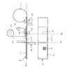
- FIG. 6 is a diagram illustrating a printer (label printer) according to an embodiment of the present invention.
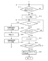
- 6 is a flowchart showing a flow (No. 1) of processing of a printing operation.
- 6 is a flowchart showing a flow (2) of a printing operation process.
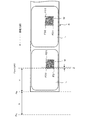
- FIG. 6 is a diagram illustrating a relationship example between a print start position Pps of a QR code finder pattern in a label (print area), a cut position Pp for cutting a sheet, and a print position Pp by a thermal head.
- FIG. 3 is a diagram illustrating a state in which a sheet is cut at a boundary portion between a first printed label and a next label in the label printer illustrated in FIG. 2.
- FIG. 5 is a diagram illustrating an example in which two finder patterns arranged on one side of a QR code do not simultaneously become print positions.
- FIG. 5 is a diagram without closing an example in which the QR code is rotated by 90 ° so that two finder patterns arranged on one side of the QR code are not in the print position at the same time.
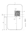
- FIG. 8 is a diagram illustrating an example in which white spots are applied to the QR code illustrated in FIG. 7. It is a figure which shows the other relationship example of the print start position of the QR Code finder pattern in a label, the cut position which cuts a paper, and the print position Pp by a thermal head.
- a printer (label printer) according to an embodiment of the present invention is configured as shown in FIG. *
- a sheet S in which labels (print areas) are temporarily attached to a mount with a predetermined width at a predetermined interval is wound around a roll 11, and the sheet S fed from the roll 11 by a feed roller 12 is transported 100.
- This label printer is a thermal transfer printer.
- a thermal head 23 is disposed at a predetermined position on the conveyance path 100 and a platen roller 24 is disposed so as to face the thermal head 23.
- the ink ribbon 20 is wound between the feed roller 21 and the take-up roller 22, and the ink ribbon 20 fed from the feed roller 21 is taken up by the take-up roller 22 via a plurality of tension rollers. .
- the ink ribbon 20 and the sheet S moving on the transport path 100 overlap each other and pass between the thermal head 23 and the platen roller 24.
- a paper position sensor 13 for detecting the leading edge of the paper S fed from the roll 11 is provided at a predetermined position near the feeding roller 12.
- a cutter 14 for cutting the paper S is provided at a predetermined position downstream from the position (printing position) of the thermal head 23 in the moving direction of the paper S.
- the label printer has a controller 10 that controls the printing operation.
- the controller 10 applies the information necessary for printing (print information) such as the detection signal from the paper position detection sensor 13, the print data from the host device 30 such as a personal computer, and format data (print information) to the paper S of the ink ribbon 20.
- Print information information necessary for printing
- the host device 30 such as a personal computer
- format data print information
- Control related to the printing operation for each label (print region) of the paper S such as drive control of the thermal head 23 that performs thermal transfer of the paper, feed control of the paper S, and drive control of the cutter 14 is performed.
- the information represented by the print data is printed on a predetermined area of each label of the paper S moving on the transport path 100 by the printing operation controlled by the controller 10, and the paper S is cut and a printed label is printed. Cut out from the paper S.
- the controller 10 performs processing related to the printing operation according to the procedure shown in FIGS. *
- the sheet S fed from the roll 11 by the feed roller 12 is set at a position (initial position) where the leading end is detected by the sheet position sensor 13 as shown in FIG. .
- the controller 10 prints print data representing information to be printed together with a print request from the host device 30 (personal computer), format data representing a print format (position and shape of information to be printed, label, etc.), and the like. Is acquired (S11), print data is extracted from the print information, and the print data is set in a predetermined memory (S12). Thereafter, the controller 10 sets the print data in a predetermined direction with respect to the label (for example, as shown in FIG.
- the two finder patterns FD1 and FD2 on one side are on the most downstream side in the moving direction of the paper S). Whether or not data representing a QR code to be printed is included (in a direction in which the two finder patterns FD2 and FD3 on the other side are aligned in parallel with the moving direction of the paper S). Is determined (S13). *
- the controller 10 When the print data includes data representing a QR code to be printed in a predetermined direction with respect to the label (YES in S13), the controller 10 further prints the print data, format data, thermal head 23, When printing according to the print data on each label of the paper S based on the information related to the position of the cutter 14, as shown in FIG. 6, the boundary between the first printed label Ln and the next label Ln + 1 When the position reaches the cut position Pc (position at which the cutter 14 is disposed), both the finder patterns FD1 and FD2 (see FIG.
- the distance X1 between the cut position Pc and the print position Pp1 is from the leading edge (cut position) of the paper S.
- the distance between the finder patterns FD1 and FD2 of the QR code M is smaller than the distance Y, when the boundary between the first printed label Ln and the next label Ln + 1 reaches the cut position Pc, the QR code M at the next label Ln + 1
- Both the finder patterns FD1 and FD2 (see FIG. 5) arranged on one side do not reach the position Pp1 to be printed.
- the distance X2 between the cut position Pc and the print position Pp2 is the distance Y from the leading edge (cut position) of the paper S to the finder patterns FD1 and FD2 of the QR code M and the paper of each finder pattern FD1 and FD2. If it is larger than the sum of the widths Z in the moving direction (Y + Z), one side of the QR code M at the next label Ln + 1 when the boundary between the first printed label Ln and the next label Ln + 1 reaches the cut position Pc. Both of the finder patterns FD1 and FD2 (see FIG. 5) lined up in line have already passed the position Pp2 to be printed. *
- the controller 10 corrects the print data so that the QR code M is rotated 90 ° to the right to change its orientation.
- S15 the two finder patterns of the QR code M at the next label Ln + 1 become the positions Pp to be printed simultaneously. As shown in FIG. 8, only the finder pattern FD1 is the position Pp to be printed. *
- the set print data does not include a QR code (NO in S13), or if the print data includes a QR code (YES in S13), the first printed label Ln and the next printed label Ln When the boundary with the label Ln + 1 reaches the cut position Pc, the two finder patterns (for example, FD1 and FD2) arranged on one side of the QR code M in the next label Ln + 1 are not at the position Pp to be printed. In this case (NO in S14: see FIG. 7), the set print data is not corrected. *
- the controller 10 detects the leading edge by the paper position sensor 13 as shown in FIG.
- the conveyance control of the sheet S being started is started (S16).
- the sheet S starts to move on the conveyance path 100 at a predetermined speed.
- the controller 10 proceeds to the process shown in FIG. 4 and monitors whether or not the print start timing for the leading label of the sheet S has come (S17). Whether or not the print start timing has come is determined based on, for example, the position at which label printing should start based on the feed amount of the paper S, format data (label size, print start position within the label, etc.), etc. It can be determined by whether or not Pp (the position of the thermal head 23) has been reached. If the controller 10 determines that the print start timing for the leading label of the paper S has come (YES in S17), it starts driving control of the thermal head 23 based on the print data set as described above (S18). As a result, information (characters, marks, QR code M, etc.) based on the print data is printed on the leading label of the moving paper S. *
- the controller 10 determines whether or not the boundary between the first label and the next label has reached the cut position Pc (S19), and the print end timing for the first label. (S20) is monitored. When the print end timing for the first label comes (YES in S20), the controller 10 stops the drive control of the thermal head 23 and ends the print (S21). Thereafter, the controller 10 determines whether or not printing has been completed for all the specified number of labels (S22). If not (NO in S22), has the print start timing for the next label been reached? Whether or not is monitored (S17). When the print start timing for the next label comes (YES in S17), the controller 10 starts driving control of the thermal head 23 based on the set print data (S18), and printing for the next label is started. *
- the controller 10 determines whether or not the boundary between the first printed label and the next label has reached the cut position Pc (S19), and further prints for the next label. It is monitored whether or not it is the end timing (S20). In the process, when the boundary between the first printed label and the next label being printed reaches the cut position Pc (YES in S19), the controller 10 stops the conveyance of the paper S and interrupts the printing ( S23). Then, the controller 10 controls the cutter 14 to cut the paper S (S24). As a result, the first printed label is cut out from the paper S. Thereafter, the controller 10 resumes transport of the paper S and resumes printing for the next label (S25).
- the controller 10 determines whether or not the boundary between the label being printed and the next label has reached the cut position Pc (S19), and whether or not the print end timing has been reached for the label being printed (S20). ) Resume monitoring.
- the controller 10 stops the drive control of the thermal head 23 and ends the print (S21).
- the controller 10 repeatedly executes the same processing (S17 to S25) until printing for all the designated number of labels is completed (S22).
- S18 ⁇ S21 when printing is performed on each label of the moving paper S (S18 ⁇ S21), when the boundary between the first printed label and the next label being printed reaches the cut position Pc (S19).
- the controller 10 When printing is completed for all the specified number of labels (YES in S22), the controller 10 performs a cut process for the last printed label (S26). By this process, the paper S is moved without printing on the next label until the final printed label at the end reaches the cut position Pc. When the boundary between the first printed label and the next label reaches the cutting position Pc, the paper S is cut by the cutter 14 and the final printed label is cut out from the paper S.
- the boundary between the first printed label and the next label being printed reaches the cut position Pc.
- the movement of the paper S is stopped, the printing for the next label is interrupted (see S23), the boundary is cut (see S24), and the first printed label is cut out from the paper S.
- the movement of the sheet S and the printing for the next label are resumed (see S25), so that the sheet S is returned to the print position Pp after the printed label is cut out from the sheet S.
- both the two finder marks FD1 and FD2 arranged on one side of the QR code M become the print position Pp.
- the print data is corrected so that the QR code M is rotated 90 ° to the right (see FIG. 8).
- the white spot WL is applied only to the finder pattern FD1 of the QR code M as shown in FIG.
- the QR code M can be printed at a higher speed for each label sequentially arranged on the paper S in a state where data can always be restored.
- the two finder patterns FD1 and FD2 do not come to Pp at the printing position at the same time by rotating the square QR code M by 90 °, the appearance of the printed QR code M changes greatly. (See FIGS. 7 and 8). Note that the method for preventing the two finder patterns FD1 and FD2 from simultaneously reaching the print position at Pp is not limited to this, and the QR code M can be rotated at an arbitrary angle or moved forward, backward, left, or right. You may do it. *
- two finder patterns FD1 and FD2 on one side are arranged at the most downstream side in the moving direction of the sheet S and orthogonal to the moving direction, and two finder patterns on the other side.
- the print data includes data representing the QR code M to be printed in the direction in which the patterns FD2 and FD3 are arranged in parallel with the moving direction of the paper S.
- the present invention is not limited to this.
- two finder patterns FD2 and FD3 on one side are arranged on the most upstream side in the moving direction of the sheet S and orthogonal to the moving direction.
- the print data includes data representing the QR code M to be printed in the direction in which the two finder patterns FD1 and FD2 on one side are aligned in parallel with the moving direction of the paper S
- the same print as described above It is also possible to perform the operation.
- the distance X between the cut position Pc and the print position Pp the distance Y from the head of the paper S (the cut position Pc of the paper S) to the two finder patterns FD2 and FD3, and the finder patterns FD2 and FD3
- the QR code M may be rotated 90 ° to the left (see the state shown in FIG. 7).
- the printing operation is controlled so as to interrupt printing, cut the boundary portion, cut out the first printed label Ln from the paper, and then resume the movement of the paper S and printing on the label Ln.
- the printing operation is not particularly limited as long as the movement of the paper is stopped for some reason, the printing on the label is interrupted, and then the movement of the paper and the printing on the label are resumed.
- the movement of the paper S is stopped and the printing on the label Ln + 1 is interrupted, and the printed label Ln is peeled off from the mount to form a predetermined object.
- the printing operation may be controlled so that the movement of the sheet S and the printing on the label Ln are resumed.
- the paper S in which the print areas are arranged in addition to the paper in which the label is temporarily attached to the mount as described above, the paper in which tags having strips and holes formed at equal intervals are arranged as the print area, In addition, it is possible to use a sheet on which labels without a mount are arranged as a print area.
- the label printer according to the present invention is not limited to a thermal printer, and may be another type of printer.
- the label printer according to the present invention has an effect that the QR code can be printed at a higher speed in a state where data can always be restored for each label sequentially arranged on the paper.
- it is useful as a label printer in which printed labels are cut out from the paper while printing is performed on each label in the process of moving the paper on which the labels are temporarily attached to the mount.
- Controller 11 Roll 12 Feeding roller 13 Paper position sensor 14 Cutter 20 Ink ribbon 21 Feeding roller 22 Winding roller 23 Thermal head (print head) 24 Platen roller 30 Host device (personal computer) 100 Conveyance path
Landscapes
- Engineering & Computer Science (AREA)
- Physics & Mathematics (AREA)
- General Physics & Mathematics (AREA)
- Theoretical Computer Science (AREA)
- General Engineering & Computer Science (AREA)
- Record Information Processing For Printing (AREA)
- Printers Characterized By Their Purpose (AREA)
- Accessory Devices And Overall Control Thereof (AREA)
- Handling Of Sheets (AREA)
Priority Applications (2)
| Application Number | Priority Date | Filing Date | Title |
|---|---|---|---|
| US14/111,204 US8947725B2 (en) | 2011-04-13 | 2012-04-13 | Printer |
| EP12771561.3A EP2698257B1 (en) | 2011-04-13 | 2012-04-13 | Printer |
Applications Claiming Priority (2)
| Application Number | Priority Date | Filing Date | Title |
|---|---|---|---|
| JP2011-088975 | 2011-04-13 | ||
| JP2011088975A JP5657461B2 (ja) | 2011-04-13 | 2011-04-13 | プリンタ |
Publications (1)
| Publication Number | Publication Date |
|---|---|
| WO2012140914A1 true WO2012140914A1 (ja) | 2012-10-18 |
Family
ID=47009103
Family Applications (1)
| Application Number | Title | Priority Date | Filing Date |
|---|---|---|---|
| PCT/JP2012/002595 Ceased WO2012140914A1 (ja) | 2011-04-13 | 2012-04-13 | プリンタ |
Country Status (4)
| Country | Link |
|---|---|
| US (1) | US8947725B2 (enExample) |
| EP (1) | EP2698257B1 (enExample) |
| JP (1) | JP5657461B2 (enExample) |
| WO (1) | WO2012140914A1 (enExample) |
Families Citing this family (9)
| Publication number | Priority date | Publication date | Assignee | Title |
|---|---|---|---|---|
| EP3011790B1 (en) * | 2013-06-19 | 2018-01-10 | Telefonaktiebolaget LM Ericsson (publ) | Methods and devices for controlling antenna points |
| JP6111896B2 (ja) * | 2013-06-27 | 2017-04-12 | セイコーエプソン株式会社 | 媒体処理システム、印刷システム、媒体処理システムの制御方法、及び、媒体処理装置 |
| JP2016001396A (ja) * | 2014-06-11 | 2016-01-07 | 富士ゼロックス株式会社 | 画像処理装置、システム及びプログラム |
| JP6453119B2 (ja) * | 2015-03-16 | 2019-01-16 | 株式会社沖データ | 画像形成装置、及び画像形成装置の制御方法 |
| CN106240165B (zh) * | 2015-06-03 | 2018-03-09 | 精工爱普生株式会社 | 标签制作装置以及标签制作方法 |
| WO2018193151A1 (en) * | 2017-04-18 | 2018-10-25 | Upm Raflatac Oy | A method for selecting a face material for a printable label and a printed label |
| CN107870751A (zh) * | 2017-11-17 | 2018-04-03 | 珠海恒全条码设备有限公司 | 一种控件编辑方法及系统 |
| JP7225914B2 (ja) * | 2019-02-28 | 2023-02-21 | ブラザー工業株式会社 | 画像形成装置 |
| JP7275656B2 (ja) * | 2019-02-28 | 2023-05-18 | ブラザー工業株式会社 | 液体吐出装置及びプログラム |
Citations (3)
| Publication number | Priority date | Publication date | Assignee | Title |
|---|---|---|---|---|
| JP2002178577A (ja) | 2000-12-18 | 2002-06-26 | Sato Corp | ラベルプリンタ及びそのカット処理方法 |
| JP2005164655A (ja) * | 2003-11-28 | 2005-06-23 | Yokohama Rubber Co Ltd:The | 2次元コード表示物及び2次元コード表示タイヤ |
| JP2007323498A (ja) * | 2006-06-02 | 2007-12-13 | Daido Steel Co Ltd | 情報コード表示シート |
Family Cites Families (15)
| Publication number | Priority date | Publication date | Assignee | Title |
|---|---|---|---|---|
| JPH0753458B2 (ja) * | 1987-06-30 | 1995-06-07 | 株式会社テック | ラベルプリンタ |
| US5025397A (en) * | 1988-08-24 | 1991-06-18 | Tokyo Electric Co., Ltd. | Label printer |
| JP2537553B2 (ja) * | 1989-10-13 | 1996-09-25 | 株式会社テック | サ―マルプリンタ |
| US5248993A (en) * | 1990-09-07 | 1993-09-28 | Tohoku Ricoh Co., Ltd. | Thermal printer having a controller for controlling paper feed operation and a printing method thereof |
| EP0574657B1 (en) * | 1992-03-11 | 2000-11-15 | Chinon Industries Inc. | Label printing apparatus and wordprocessor |
| JP3691618B2 (ja) | 1996-04-15 | 2005-09-07 | セイコーエプソン株式会社 | テープ印刷装置 |
| US6535299B1 (en) * | 1999-09-14 | 2003-03-18 | Printronix, Inc. | Bar code verification and printing system |
| US6672510B2 (en) * | 2001-12-20 | 2004-01-06 | Scannabar (3193519 Canada Inc.) | Bar code arrangement for identifying positions along an axis |
| JP2004160981A (ja) | 2002-09-20 | 2004-06-10 | Tohoku Ricoh Co Ltd | 標印印刷・検証装置およびその印刷標印検証方法と標印印刷制御方法 |
| US7181066B1 (en) * | 2002-12-26 | 2007-02-20 | Cognex Technology And Investment Corporation | Method for locating bar codes and symbols in an image |
| JP4569382B2 (ja) * | 2005-05-20 | 2010-10-27 | ブラザー工業株式会社 | 印刷データ編集装置、印刷データ編集プログラム及び記録媒体 |
| JP4483727B2 (ja) * | 2005-07-15 | 2010-06-16 | セイコーエプソン株式会社 | 印刷画像作成装置、印刷画像作成方法およびプログラム |
| KR100828539B1 (ko) * | 2005-09-20 | 2008-05-13 | 후지제롯쿠스 가부시끼가이샤 | 이차원 코드의 검출 방법, 검출 장치, 및 검출 프로그램을기억한 기억 매체 |
| US7692812B2 (en) * | 2006-01-20 | 2010-04-06 | Lexmark International, Inc. | System, method and apparatus for registration of printed image to media orientation |
| US7988037B2 (en) * | 2009-11-02 | 2011-08-02 | Research In Motion Limited | Device and method for contact information exchange |
-
2011
- 2011-04-13 JP JP2011088975A patent/JP5657461B2/ja active Active
-
2012
- 2012-04-13 WO PCT/JP2012/002595 patent/WO2012140914A1/ja not_active Ceased
- 2012-04-13 US US14/111,204 patent/US8947725B2/en active Active
- 2012-04-13 EP EP12771561.3A patent/EP2698257B1/en not_active Not-in-force
Patent Citations (3)
| Publication number | Priority date | Publication date | Assignee | Title |
|---|---|---|---|---|
| JP2002178577A (ja) | 2000-12-18 | 2002-06-26 | Sato Corp | ラベルプリンタ及びそのカット処理方法 |
| JP2005164655A (ja) * | 2003-11-28 | 2005-06-23 | Yokohama Rubber Co Ltd:The | 2次元コード表示物及び2次元コード表示タイヤ |
| JP2007323498A (ja) * | 2006-06-02 | 2007-12-13 | Daido Steel Co Ltd | 情報コード表示シート |
Non-Patent Citations (1)
| Title |
|---|
| See also references of EP2698257A4 |
Also Published As
| Publication number | Publication date |
|---|---|
| EP2698257A4 (en) | 2014-10-01 |
| JP5657461B2 (ja) | 2015-01-21 |
| US20140036280A1 (en) | 2014-02-06 |
| US8947725B2 (en) | 2015-02-03 |
| JP2012218385A (ja) | 2012-11-12 |
| EP2698257A1 (en) | 2014-02-19 |
| EP2698257B1 (en) | 2016-03-02 |
Similar Documents
| Publication | Publication Date | Title |
|---|---|---|
| JP5657461B2 (ja) | プリンタ | |
| US10328728B2 (en) | Image recording apparatus and image recording method for printing each of a plurality of unit images | |
| JP6247011B2 (ja) | 印刷装置 | |
| EP2141023B1 (en) | Printer | |
| US10239332B2 (en) | Printer, and printer control method | |
| JP7256726B2 (ja) | 印刷装置 | |
| US9757958B2 (en) | Control method of a printing device, and printing device | |
| US20210039404A1 (en) | Printer | |
| JP4075958B2 (ja) | 印刷装置 | |
| JP4192734B2 (ja) | 媒体搬送装置およびこれを備えた画像形成装置 | |
| JP4019988B2 (ja) | 画像形成装置 | |
| JP4443760B2 (ja) | ラベルプリンタ及びそのカット処理方法 | |
| JP2011110803A (ja) | 画像記録装置、及び画像記録装置の制御方法 | |
| JP2013184324A (ja) | 画像形成装置及び画像形成方法 | |
| JP2019005913A (ja) | 記録装置および記録制御方法 | |
| JP7822252B2 (ja) | 印刷制御装置、印刷制御方法、印刷制御プログラム | |
| JP6372595B2 (ja) | 印刷装置 | |
| US11628677B2 (en) | Printing apparatus and printing control method | |
| US8905510B2 (en) | Printer | |
| JP4473682B2 (ja) | 印字装置 | |
| JP6235285B2 (ja) | 印刷装置及び印刷制御装置並びに印刷制御方法 | |
| JP4838656B2 (ja) | 熱転写プリンタ | |
| JP2010012663A (ja) | 印刷装置 | |
| JP2019014050A (ja) | 記録装置 | |
| JP2021094831A (ja) | インクリボン及び画像形成装置 |
Legal Events
| Date | Code | Title | Description |
|---|---|---|---|
| 121 | Ep: the epo has been informed by wipo that ep was designated in this application |
Ref document number: 12771561 Country of ref document: EP Kind code of ref document: A1 |
|
| WWE | Wipo information: entry into national phase |
Ref document number: 2012771561 Country of ref document: EP |
|
| WWE | Wipo information: entry into national phase |
Ref document number: 14111204 Country of ref document: US |
|
| NENP | Non-entry into the national phase |
Ref country code: DE |