EP2684243B1 - Battery pack system - Google Patents
Battery pack system Download PDFInfo
- Publication number
- EP2684243B1 EP2684243B1 EP12711691.1A EP12711691A EP2684243B1 EP 2684243 B1 EP2684243 B1 EP 2684243B1 EP 12711691 A EP12711691 A EP 12711691A EP 2684243 B1 EP2684243 B1 EP 2684243B1
- Authority
- EP
- European Patent Office
- Prior art keywords
- cells
- battery
- switcher chip
- switcher
- positive terminal
- Prior art date
- Legal status (The legal status is an assumption and is not a legal conclusion. Google has not performed a legal analysis and makes no representation as to the accuracy of the status listed.)
- Active
Links
Images


Classifications
-
- H—ELECTRICITY
- H02—GENERATION; CONVERSION OR DISTRIBUTION OF ELECTRIC POWER
- H02J—CIRCUIT ARRANGEMENTS OR SYSTEMS FOR SUPPLYING OR DISTRIBUTING ELECTRIC POWER; SYSTEMS FOR STORING ELECTRIC ENERGY
- H02J7/00—Circuit arrangements for charging or depolarising batteries or for supplying loads from batteries
- H02J7/0013—Circuit arrangements for charging or depolarising batteries or for supplying loads from batteries acting upon several batteries simultaneously or sequentially
- H02J7/0024—Parallel/serial switching of connection of batteries to charge or load circuit
-
- B—PERFORMING OPERATIONS; TRANSPORTING
- B60—VEHICLES IN GENERAL
- B60L—PROPULSION OF ELECTRICALLY-PROPELLED VEHICLES; SUPPLYING ELECTRIC POWER FOR AUXILIARY EQUIPMENT OF ELECTRICALLY-PROPELLED VEHICLES; ELECTRODYNAMIC BRAKE SYSTEMS FOR VEHICLES IN GENERAL; MAGNETIC SUSPENSION OR LEVITATION FOR VEHICLES; MONITORING OPERATING VARIABLES OF ELECTRICALLY-PROPELLED VEHICLES; ELECTRIC SAFETY DEVICES FOR ELECTRICALLY-PROPELLED VEHICLES
- B60L58/00—Methods or circuit arrangements for monitoring or controlling batteries or fuel cells, specially adapted for electric vehicles
- B60L58/10—Methods or circuit arrangements for monitoring or controlling batteries or fuel cells, specially adapted for electric vehicles for monitoring or controlling batteries
- B60L58/18—Methods or circuit arrangements for monitoring or controlling batteries or fuel cells, specially adapted for electric vehicles for monitoring or controlling batteries of two or more battery modules
- B60L58/19—Switching between serial connection and parallel connection of battery modules
-
- B—PERFORMING OPERATIONS; TRANSPORTING
- B60—VEHICLES IN GENERAL
- B60L—PROPULSION OF ELECTRICALLY-PROPELLED VEHICLES; SUPPLYING ELECTRIC POWER FOR AUXILIARY EQUIPMENT OF ELECTRICALLY-PROPELLED VEHICLES; ELECTRODYNAMIC BRAKE SYSTEMS FOR VEHICLES IN GENERAL; MAGNETIC SUSPENSION OR LEVITATION FOR VEHICLES; MONITORING OPERATING VARIABLES OF ELECTRICALLY-PROPELLED VEHICLES; ELECTRIC SAFETY DEVICES FOR ELECTRICALLY-PROPELLED VEHICLES
- B60L58/00—Methods or circuit arrangements for monitoring or controlling batteries or fuel cells, specially adapted for electric vehicles
- B60L58/10—Methods or circuit arrangements for monitoring or controlling batteries or fuel cells, specially adapted for electric vehicles for monitoring or controlling batteries
- B60L58/18—Methods or circuit arrangements for monitoring or controlling batteries or fuel cells, specially adapted for electric vehicles for monitoring or controlling batteries of two or more battery modules
- B60L58/21—Methods or circuit arrangements for monitoring or controlling batteries or fuel cells, specially adapted for electric vehicles for monitoring or controlling batteries of two or more battery modules having the same nominal voltage
-
- H—ELECTRICITY
- H01—ELECTRIC ELEMENTS
- H01M—PROCESSES OR MEANS, e.g. BATTERIES, FOR THE DIRECT CONVERSION OF CHEMICAL ENERGY INTO ELECTRICAL ENERGY
- H01M10/00—Secondary cells; Manufacture thereof
- H01M10/04—Construction or manufacture in general
- H01M10/0445—Multimode batteries, e.g. containing auxiliary cells or electrodes switchable in parallel or series connections
-
- H—ELECTRICITY
- H01—ELECTRIC ELEMENTS
- H01M—PROCESSES OR MEANS, e.g. BATTERIES, FOR THE DIRECT CONVERSION OF CHEMICAL ENERGY INTO ELECTRICAL ENERGY
- H01M10/00—Secondary cells; Manufacture thereof
- H01M10/42—Methods or arrangements for servicing or maintenance of secondary cells or secondary half-cells
- H01M10/4207—Methods or arrangements for servicing or maintenance of secondary cells or secondary half-cells for several batteries or cells simultaneously or sequentially
-
- H—ELECTRICITY
- H01—ELECTRIC ELEMENTS
- H01M—PROCESSES OR MEANS, e.g. BATTERIES, FOR THE DIRECT CONVERSION OF CHEMICAL ENERGY INTO ELECTRICAL ENERGY
- H01M10/00—Secondary cells; Manufacture thereof
- H01M10/42—Methods or arrangements for servicing or maintenance of secondary cells or secondary half-cells
- H01M10/425—Structural combination with electronic components, e.g. electronic circuits integrated to the outside of the casing
-
- H—ELECTRICITY
- H02—GENERATION; CONVERSION OR DISTRIBUTION OF ELECTRIC POWER
- H02J—CIRCUIT ARRANGEMENTS OR SYSTEMS FOR SUPPLYING OR DISTRIBUTING ELECTRIC POWER; SYSTEMS FOR STORING ELECTRIC ENERGY
- H02J7/00—Circuit arrangements for charging or depolarising batteries or for supplying loads from batteries
-
- B—PERFORMING OPERATIONS; TRANSPORTING
- B60—VEHICLES IN GENERAL
- B60L—PROPULSION OF ELECTRICALLY-PROPELLED VEHICLES; SUPPLYING ELECTRIC POWER FOR AUXILIARY EQUIPMENT OF ELECTRICALLY-PROPELLED VEHICLES; ELECTRODYNAMIC BRAKE SYSTEMS FOR VEHICLES IN GENERAL; MAGNETIC SUSPENSION OR LEVITATION FOR VEHICLES; MONITORING OPERATING VARIABLES OF ELECTRICALLY-PROPELLED VEHICLES; ELECTRIC SAFETY DEVICES FOR ELECTRICALLY-PROPELLED VEHICLES
- B60L2200/00—Type of vehicles
- B60L2200/26—Rail vehicles
-
- H—ELECTRICITY
- H01—ELECTRIC ELEMENTS
- H01M—PROCESSES OR MEANS, e.g. BATTERIES, FOR THE DIRECT CONVERSION OF CHEMICAL ENERGY INTO ELECTRICAL ENERGY
- H01M10/00—Secondary cells; Manufacture thereof
- H01M10/04—Construction or manufacture in general
- H01M10/0413—Large-sized flat cells or batteries for motive or stationary systems with plate-like electrodes
-
- H—ELECTRICITY
- H01—ELECTRIC ELEMENTS
- H01M—PROCESSES OR MEANS, e.g. BATTERIES, FOR THE DIRECT CONVERSION OF CHEMICAL ENERGY INTO ELECTRICAL ENERGY
- H01M10/00—Secondary cells; Manufacture thereof
- H01M10/04—Construction or manufacture in general
- H01M10/0436—Small-sized flat cells or batteries for portable equipment
-
- H—ELECTRICITY
- H01—ELECTRIC ELEMENTS
- H01M—PROCESSES OR MEANS, e.g. BATTERIES, FOR THE DIRECT CONVERSION OF CHEMICAL ENERGY INTO ELECTRICAL ENERGY
- H01M10/00—Secondary cells; Manufacture thereof
- H01M10/42—Methods or arrangements for servicing or maintenance of secondary cells or secondary half-cells
- H01M10/425—Structural combination with electronic components, e.g. electronic circuits integrated to the outside of the casing
- H01M2010/4271—Battery management systems including electronic circuits, e.g. control of current or voltage to keep battery in healthy state, cell balancing
-
- H—ELECTRICITY
- H01—ELECTRIC ELEMENTS
- H01M—PROCESSES OR MEANS, e.g. BATTERIES, FOR THE DIRECT CONVERSION OF CHEMICAL ENERGY INTO ELECTRICAL ENERGY
- H01M10/00—Secondary cells; Manufacture thereof
- H01M10/42—Methods or arrangements for servicing or maintenance of secondary cells or secondary half-cells
- H01M10/425—Structural combination with electronic components, e.g. electronic circuits integrated to the outside of the casing
- H01M2010/4278—Systems for data transfer from batteries, e.g. transfer of battery parameters to a controller, data transferred between battery controller and main controller
-
- H—ELECTRICITY
- H01—ELECTRIC ELEMENTS
- H01M—PROCESSES OR MEANS, e.g. BATTERIES, FOR THE DIRECT CONVERSION OF CHEMICAL ENERGY INTO ELECTRICAL ENERGY
- H01M2220/00—Batteries for particular applications
- H01M2220/20—Batteries in motive systems, e.g. vehicle, ship, plane
-
- Y—GENERAL TAGGING OF NEW TECHNOLOGICAL DEVELOPMENTS; GENERAL TAGGING OF CROSS-SECTIONAL TECHNOLOGIES SPANNING OVER SEVERAL SECTIONS OF THE IPC; TECHNICAL SUBJECTS COVERED BY FORMER USPC CROSS-REFERENCE ART COLLECTIONS [XRACs] AND DIGESTS
- Y02—TECHNOLOGIES OR APPLICATIONS FOR MITIGATION OR ADAPTATION AGAINST CLIMATE CHANGE
- Y02E—REDUCTION OF GREENHOUSE GAS [GHG] EMISSIONS, RELATED TO ENERGY GENERATION, TRANSMISSION OR DISTRIBUTION
- Y02E60/00—Enabling technologies; Technologies with a potential or indirect contribution to GHG emissions mitigation
- Y02E60/10—Energy storage using batteries
-
- Y—GENERAL TAGGING OF NEW TECHNOLOGICAL DEVELOPMENTS; GENERAL TAGGING OF CROSS-SECTIONAL TECHNOLOGIES SPANNING OVER SEVERAL SECTIONS OF THE IPC; TECHNICAL SUBJECTS COVERED BY FORMER USPC CROSS-REFERENCE ART COLLECTIONS [XRACs] AND DIGESTS
- Y02—TECHNOLOGIES OR APPLICATIONS FOR MITIGATION OR ADAPTATION AGAINST CLIMATE CHANGE
- Y02P—CLIMATE CHANGE MITIGATION TECHNOLOGIES IN THE PRODUCTION OR PROCESSING OF GOODS
- Y02P70/00—Climate change mitigation technologies in the production process for final industrial or consumer products
- Y02P70/50—Manufacturing or production processes characterised by the final manufactured product
-
- Y—GENERAL TAGGING OF NEW TECHNOLOGICAL DEVELOPMENTS; GENERAL TAGGING OF CROSS-SECTIONAL TECHNOLOGIES SPANNING OVER SEVERAL SECTIONS OF THE IPC; TECHNICAL SUBJECTS COVERED BY FORMER USPC CROSS-REFERENCE ART COLLECTIONS [XRACs] AND DIGESTS
- Y02—TECHNOLOGIES OR APPLICATIONS FOR MITIGATION OR ADAPTATION AGAINST CLIMATE CHANGE
- Y02P—CLIMATE CHANGE MITIGATION TECHNOLOGIES IN THE PRODUCTION OR PROCESSING OF GOODS
- Y02P90/00—Enabling technologies with a potential contribution to greenhouse gas [GHG] emissions mitigation
- Y02P90/60—Electric or hybrid propulsion means for production processes
-
- Y—GENERAL TAGGING OF NEW TECHNOLOGICAL DEVELOPMENTS; GENERAL TAGGING OF CROSS-SECTIONAL TECHNOLOGIES SPANNING OVER SEVERAL SECTIONS OF THE IPC; TECHNICAL SUBJECTS COVERED BY FORMER USPC CROSS-REFERENCE ART COLLECTIONS [XRACs] AND DIGESTS
- Y02—TECHNOLOGIES OR APPLICATIONS FOR MITIGATION OR ADAPTATION AGAINST CLIMATE CHANGE
- Y02T—CLIMATE CHANGE MITIGATION TECHNOLOGIES RELATED TO TRANSPORTATION
- Y02T10/00—Road transport of goods or passengers
- Y02T10/60—Other road transportation technologies with climate change mitigation effect
- Y02T10/70—Energy storage systems for electromobility, e.g. batteries
Definitions
- This disclosure relates to the field of battery pack systems. In some embodiments, it relates to electric vehicle (EV) battery pack systems and also EV power train systems.
- EV electric vehicle
- An EV battery pack typically includes several battery modules, each comprised out of several batteries (e.g., several single cell batteries), that are packed into a hardened package.
- the specification of the battery pack is determined by the car manufacturer and takes into consideration the extreme needs of the engine and the expected environmental conditions. Thus the specification usually calls for extra battery modules and/or for extra material, such as electrolyte, to be added to the cells to compensate for production faults and degradation of the batteries over time.
- EV battery packs have a fixed current and voltage output.
- US 2010/261048 describes a reconfigurable framework for a large-scale battery system having a battery cell array.
- the improved battery pack system includes battery pack that includes a switching grid coupled to a main controller.
- the switching grid includes a plurality of battery modules and a wiring structure that enables the controller to change the configuration of the batteries (e.g., cells) within the battery module and/or battery pack.
- This switching grid is used to change the output of the battery pack to fit the engine's current needs.
- the improved battery pack may be configured to take into consideration the concurrent state of each battery in the battery pack and environmental condition as well as the battery history information and the manufacturer recommendations.
- a battery pack comprising: a main controller, and a plurality of switcher chips for use in interconnecting a set plurality of cells.
- each switcher chip comprises a switching control logic; and a communication circuit; the communication circuit comprising: a transmitter, and a receiver, wherein the receiver is communicatively connected in use to either the main controller or a transmitter of an adjacent switcher chip such that the receiver is operable to receive switching commands transmitted from either the main controller or the transmitter of the adjacent switcher chip, and wherein the transmitter is for transmitting switching commands to another adjacent switcher chip.
- the battery pack further comprising: a main negative terminal of a first switcher chip connected to a main positive terminal of a second switcher chip; a negative terminal of the first switcher chip; a main positive terminal of the first switcher chip connected to a main positive terminal of a third switcher chip; a positive terminal of a first switcher chip connected to a negative terminal of a fourth switcher chip; a plurality of cell terminals; and a plurality of switches.
- the first switcher chip is configured such that: when a set of cells are connected to the first switcher chip via the plurality of cell terminals and a first set of the plurality of switches are closed and the remainder of the switches are open, the set of cells are connected in parallel with each other and current is able to flow through the set of cells and out of the main positive terminal but is not able to flow out of the positive terminal, when the set of cells are connected to the first switcher chip via the plurality of cell terminals and a second set of the plurality of switches are closed and the remainder of the switches are open, the set of cells are connected in series with each other and current is able to flow through the set of cells and out of the main positive terminal but is not able to flow out the positive terminal, when the set of cells are connected to the first switcher chip via the plurality of cell terminals and a third set of the plurality of switches are closed and the remainder of the switches are open, at least two of the cells in the set of cells are connected in series with each other and current is able to flow through the set of
- the switcher chips further comprise a command decoder configured to error check commands received by the communication circuit from the main controller or from another switcher chip and configured to block erroneous commands.
- the switcher chips further comprise the switching control logic connected to the command decoder and configured to convert commands received by the communication circuit from the main controller into switch on-off commands for switching elements within the battery pack.
- the switcher chips further comprise a safety switching sequencer configured to receive the on-off commands from the switching control logic and configured to turn on or off at exact sequence and time one or more of the switches based on the received on-off commands.
- the switcher chips further comprise a slave input terminal; a master output terminal; the receiver being a slave communication module block; the transmitter being a master communication module block; a command decoder block; and a safety switching sequencer block.
- the plurality of switches comprises a plurality of power metal-oxide semiconductor field effect transistors (MOSFETs).
- MOSFETs power metal-oxide semiconductor field effect transistors
- a battery apparatus comprises: a first switcher chip, a second switcher chip, a third switcher chip, and a fourth switcher chip; and each switcher chip comprising: a switching control logic, and a communication circuit, wherein the communication circuit comprises: a transmitter, and a receiver, wherein each receiver is communicatively connected in use to either a main controller or a transmitter of an adjacent switcher chip such that the receiver is operable to receive switching commands transmitted from either the main controller or the transmitter of the adjacent switcher chip, and wherein the transmitter is for transmitting switching commands to another adjacent switcher chip.
- the first switcher chip further comprising: a first plurality of switches, a first main positive terminal, a first main negative terminal, a first cascading positive terminal and a first cascading negative terminal; and a set of cells, the set of cells comprising: (i) a first cell having a positive terminal and a negative terminal, the positive terminal being connected to a first cell terminal of the first switcher chip and the negative terminal being connected to a second cell terminal of the first switcher chip, and (ii) a second cell having a positive terminal and a negative terminal, the positive terminal is connected to a third cell terminal of the first switcher chip and the negative terminal is connected to a fourth cell terminal of the first switcher chip, the second switcher chip further comprising: a second plurality of switches, a second main positive terminal and a second main negative terminal, the second main positive terminal of the second switcher chip being connected to the first main negative terminal of the first switcher chip; the third switcher chip (301a) comprising: a third plurality of switches, a
- each of the first, second, third, and fourth switcher chips further comprise: a command decoder configured to error check commands received by the communication circuit from the controller or from another switcher chip and configured to block erroneous commands.
- each of the first, second, third, and fourth switcher chips further comprise: the switching control logic connected to the command decoder and configured to convert commands received by the communication circuit from the controller into switch on-off commands for switching elements within the battery module.
- each of the first, second, third, and fourth switcher chips further comprise: a safety switching sequencer configured to receive the on-off commands from the switching control logic and configured to turn on or off at exact sequence and time one or more of the switches based on the received on-off commands.
- the first cell is a micro-cell and the second cell is a micro-cell.
- the switcher chip controls less than seventeen single cell batteries but more than three single cell batteries.
- each of the first, second, third, and fourth switcher chips control more than 7 single cell batteries and less than 13 single cell batteries.
- the battery apparatus comprises a battery pack that comprises: a first cluster of battery modules comprising a first column of battery modules and a second column of battery modules; a first circuit for connecting the first column of battery modules in parallel with the second column of battery modules; a second circuit for connecting the first column of battery modules in series with the second column of battery modules; a second cluster of battery modules comprising a third column of battery modules and a fourth column of battery modules; a third circuit for connecting the third column of battery modules in parallel with the fourth column of battery modules; a fourth circuit for connecting the third column of battery modules in series with the fourth column of battery modules, wherein at least one of the battery modules in the first column has (i) a switch for connecting and disconnecting a main output of the battery module to the first circuit and (ii) a switch for connecting and disconnecting a cascading output of the battery module to the second circuit, at least one of the battery modules in the second column has (i) a switch for connecting and disconnecting a main output of the battery module to the first circuit
- the controller may be operable to: (a) place the battery pack in a first mode of operation in which the battery pack produces a voltage V1; and (b) place the battery pack in second mode of operation in which the battery pack produces a voltage V2, where V2 > VI.
- V2 may be greater than or equal to (n)(3.6)V1, where n is greater than or equal to 1.
- At least one of the battery modules comprises: a switcher chip comprising: a plurality of switches, a main positive terminal, a main negative terminal, a cascading positive terminal and a cascading negative terminal; and a set of cells comprising (i) a first cell having a positive terminal and a negative terminal, the positive terminal being connected to a first cell terminal of the switcher chip and the negative terminal being connected to a second cell terminal of the switcher chip, and (ii) a second cell having a positive terminal and a negative terminal, the positive terminal is connected to a third cell terminal of the switcher chip and the negative terminal is connected to a fourth cell terminal of the switcher chip.
- the controller is operable to: (i) cause the battery module to configure the switches such that (a) the cells are connected in series, (b) current is able to flow out of the switcher chip via the main positive terminal but is not able to flow out the switcher chip via the cascading positive terminal, and (c) current is able to flow into the switcher chip via the main negative terminal but is not able to flow into the switcher chip via the cascading negative terminal, (ii) cause the battery module to configure the switches such that (a) the cells are connected in series, (b) current is able to flow out of the switcher chip via the cascading positive terminal but is not able to flow out the switcher chip via the main positive terminal, and (c) current is able to flow into the switcher chip via the cascading negative terminal but is not able to flow into the switcher chip via the main negative terminal, and (iii) cause the battery module to configure the switches such that (a) the cells are connected in parallel, (b) current is
- Conventional battery pack systems comprise a moderate numbers of batteries and a number of controllers, each of which monitors a group of the batteries (e.g., 10 of the batteries) for safety reasons mostly.
- a controller senses the voltage, temperature, and current of each battery in the group and, during the regular operation of the battery pack, levels the amount of charge in each battery by discharging batteries that are overcharged.
- the controller sends a signals to an aggregator controller that than shuts off a main power switch to disconnect the battery pack from the electric engine. This mechanism is fine for the sake of safety but does not apply to the other parameters needed from the battery pack.
- the nominal voltage of a cell is determined by the cell chemistry which is the electrochemical parameters of the chemicals used for the production. But when used, the actual voltage on the cell terminals changes over time and depends of various parameters that affect the internal impedance of the cells, like the ambient temperature, the state of charge of the cells, the age of the cell, as well as the actual load current.
- FIG. 1 is a diagram illustrating a battery pack system 100, according to some embodiments, which overcomes at least some of the deficiencies of conventional battery pack systems.
- battery pack system 100 includes a battery pack 104, which includes (i) several batteries 101 (e.g., several single cell batteries - which we shall refer to as a "cell") and (ii) a battery switching grid 102 (a.k.a., "3D Battery Switching GridTM”302) that enables the connection of the cells 101 in various different modes.
- the 3D Battery Switching Grid includes a plurality of low cost chips (a.k.a., "switcher chips”), each of which is responsible for configuring a particular subset of the cells of the battery pack and each of which contains a set of switches connected to the particular subset of cells and circuit logic for controlling the switches.
- Battery pack system 100 may further include a main controller 106 (a.k.a., EV ProcessorTM) that monitors the state of each cell by its sensing the cell's specific parameters (e.g., state of charge, voltage, current, temperature, pressure etc.) and controls the switching grid based on, at least in part, the current needs of the engine and the sensed parameters.
- the controller may also take into account the usage history of the cells, the manufacturer motor behavior diagrams, and driver history and desires. Accordingly, battery pack system 100 enables more efficient power utilization of the cells, increases safety, and provides the best suited power source for different motors and for the current needs of that motor based on the driver's behavior and directions and the driving environment.
- the EV Processor incorporated within battery pack 104.
- the battery pack system 100 includes a number of cells that are each monitored separately and can be electrically interconnected in various modes (e.g., parallel, serial or any other structure) during the usage by the car engine and during the charge time.
- This way in which the cells are electrically interconnected may be changed periodically by the EV Processor to best match the actual needs of the car (e.g., if high torque is needed the battery system can be configured to provide a maximum amount of current.
- the specific configuration of each cell is determined by its current status, its history and the current task being performed as well as environmental conditions.
- the battery pack system 100 needs to perform in low temperature conditions more cells can be connected in series to compensate for the degraded voltage contribution of each cell. This method is also applicable for compensating of degradation in time. As another example, if a certain cell is malfunctioning, the malfunctioning cell may be electrically excluded from the battery pack structure and the negative effect of its fault will be prevented.
- the cells may be relatively small (e.g., the cells may have a relatively small capacity - such as 2Ah v. 20Ah, for example), in which case they may be referred to as micro-cells.
- the cells may have a relatively small capacity - such as 2Ah v. 20Ah, for example
- micro-cells With the use of micro-cells management tasks can be done at adequate granularity and the battery manufacturer can design the battery in a much more optimal manner and can than reach higher power capacity and better performance over time for the same weight and volume.
- Another advantage of using micro-cells is that because they are smaller they can be used more cycles and the heat dissipation from them is better.
- An EV battery pack is a fairly large object that consumes significant car space and weight. There is a tradeoff in the design of a battery pack between energy capacity, space and weight - for the sake of more energy you would want to enlarge the battery pack, but this cost a lot in expensive material, space consumed in the car and additional car weight.
- Conventional battery packs are designed for providing the maximum voltage and current needed for the electric engine used and the energy capacity needed between charges and for the sake of the battery lifetime.
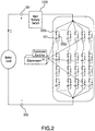
- FIG. 2 illustrates the 3D Switching Grid concept.
- battery pack 104 includes not only a collection of cells 101, but also a collection of switches 202.
- switches 202 As further illustrated in the embodiment shown in FIG. 2 , at least two switches are present for each cell 101.
- switch 202a and switch 202b are used to either (1) connect cell 101a in series with other cells or (2) electrically disconnect cell 101a from all the other cells.
- each cell in battery pack 104 can be electrically included in the batter pack or electrically excluded from the battery pack.
- the switching grid enables creating a structure that provides higher voltage, higher peak current or different cell order. It enables to charge the cells in different order and to use part or all of the cells in different utilization cases and by that optimizing the wear-out of the battery over the years. It will also enable to employ a safer use method because of the ability to temporarily or permanently electrically exclude malfunctioning cells from the pack 104 in an early stage of a problematic situation without the need to switch off the whole battery and stop the car.
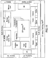
- FIG. 3 illustrates an example structure of battery pack 104 according to some embodiments.
- the example battery pack 104 includes two clusters of battery modules 301.
- the first cluster (cluster 1) is made of two sets (or “columns") of M battery modules (col. 1a and col. 1b) and a cascade wire 585 that is used to connect col. 1a and co1. 1b in series.
- the second cluster (cluster 2) is made of two sets (or "columns") of M battery modules (col. 2a and col. 2b) and a cascade wire that is used to connect col. 2a and co1. 2b in series.
- M 3.
- battery module 301 includes a set of cells (e.g., 4 cells, 8 cells, or some other number of cells) and a component of the switching grid 102 (e.g., one of the switcher chips mentioned above that contain a set of switches).
- a set of cells e.g., 4 cells, 8 cells, or some other number of cells
- a component of the switching grid 102 e.g., one of the switcher chips mentioned above that contain a set of switches.
- col. 1a will either be in parallel with col. 1b or they will be in series.
- col. 2a will either be in parallel with col. 2b or they will be in series.
- battery pack 104 may have at least two modes of operation: in one mode the columns in each cluster are connected in parallel and in another the columns in each cluster are connected in series. It is not required, however, that all columns in a cluster be connected in series or parallel.
- each battery module 301 can be configured such that it produces Va volts or Vb volts depending on whether the cells of the battery module are connected in series or parallel. If each battery module produces Vi volts (e.g., Va or Vb) and the all the columns of each cluster are connected in parallel, then the battery pack 104 produces MxVi volts.
- a main controller may configured battery pack 104 based on, for example, data regarding the needs of the engine and/or the environment.
- the main controller could send one or more commands to the battery pack that cause the battery pack to connect the columns within each cluster in series and/or the cells within each battery module in series.
- the main controller could send one or more commands to the battery pack that cause the battery pack to connect the columns within each cluster in parallel and/or the cells within each battery module in parallel.
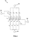
- FIGs. 4-8 illustrate an example battery module 301, which includes four batteries c1, c2, c3, c4 (e.g., four micro-cells), a set of swtiches (s0 through s14), a main positive terminal 402, a main negative terminal 404, a cascading positive terminal 582, and a cascading negative terminal 581.
- batteries c1-c4 as cells with the understanding that the batteries are not limited to single-cell devices.
- Switches s1-s4, s6-s8 and s10-s13 are used for interconnecting cells c1-c4, while switches s0, s5, s9 and s14 are used for cascading columns in a cluster. That is, switches s0, s5, s9 and s14 enable the battery module to connect in series with another battery module in a neighboring column of the same cluster.
- terminals 581 and 582 are each connected to a respective cascade wire. The other end of the cascade wire is connected to a corresponding cascade terminal in a battery module that is positioned in an adjacent column. For instance, as shown in FIG.
- terminal 581 of module 301a is connected to wire 585 and the other end of the wire is connected to terminal 582 of module 301b.
- module 301a is configured such that the following switches are closed s4-s8 and the others are open and
- module 301b is configured such that the following switches are closed s6-s10 and the others are open
- a battery module (components of which may be formed on a single chip) according to various embodiments of the invention is capable of switching C cells that can be connected in serial, parallel or excluded from the grid.
- a battery module is capable of electrically connecting C cells in parallel or in series.
- the battery module can electrically disconnect the cell from all of the other cells in the battery module. Accordingly, a battery module has responsibility for C cells of the battery pack.
- Another advantage of the above structure is that the energy capacity redundancy designed by the manufacturer can be spread wisely within the pack and can be utilized to provide more current or more voltage according to the actual needs of the engine in any given time.
- battery module 301 may be implemented as an integrated circuit or "microchip” ("chip” for short). That is, in some embodiments, battery module 301 comprises a chip and a set of cells connected to the chip. The chip is responsible for configuring the set of cells. For example, the chip is responsible for connecting the cells either in series with each other or in parallel with each other. The chip may include digital, analog and communication components. The chip may make use of a noise-resilient communication module that decreases possible control errors to the automotive levels needed as well as prevents unauthorized designers to make use of the module. In some embodiments, the chip uses Power FET technology for the switching elements enabling very low Rds-on that leads to low self power dissipation needed for energy efficiency.
- the chip may also include a safety switching sequencer that manages the exact switching sequence and time of an individual cell to prevent hazardous situations.
- the chip may include a small CPU and software code that in addition to taking actions in response to commands received from a controller can also act like a controller for certain tasks and react to specific localized situations and take autonomic specific actions such as, for instance, immediately switching-out a certain cell, or several sells, that the chip senses is malfunctioning.
- the switching elements need to support switching time that relates to the application using the battery. In the case of an EV car, the switching time needed is relatively slow and do not pose significant needs from the switching elements, for instance the Power MOSFET mentioned
- the constellations in which the switching elements are arranged within the battery module determines the level of flexibility when building the battery switching grid. It is preferable to keep the number of switching elements per battery module as low as possible in order to be able to design a cost effective solution. Moreover, it is also preferable that each of the switching elements need to bear only 1xI and thus can be relatively small.
- the connection that aggregate the currents from several cells is done outside the chip of the battery module and utilize several terminals of the chip.
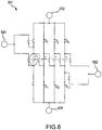
- FIG. 5 shows the battery module being configured such that all of the cells of the module are connected in parallel with each other. That is, c1 is parallel with c2, which is parallel with c3, which is parallel with c4. This is accomplished by closing switches s1-s4 and s10-s13 and keeping the others open.
- FIG. 6 shows the battery module being configured so that cell c1 is excluded from the parallel circuit. This is accomplished by closing switches s2-s4 and s11-s13 and keeping the other switches open.
- FIG. 7 shows the battery module being configured such that all of the cells of the module are connected in in series. That is, c1 is in series with c2, which is in series with c3, which is in series with c4. This is accomplished by closing switches s4, s6-s8, s10 and keeping the others open. In this configuration, current (i.e., conventional current) is able to flow out of main positive terminal 402 and current is able to flow into main negative terminal 404. If cascading is desired, then switches s5 and s9 are closed and switches s4 and s10 are opened.
- current i.e., conventional current
- FIG. 8 shows the battery module being configured so that cell c1 is excluded from the series circuit. This is accomplished by closing switches s4, s7, s8, s11 and keeping the others open.
- the switches are connected in a way that enables to still make use of most of the other cell's while the problematic one is fully excluded from the module.
- the switches e.g, Power FETs
- the switches have a very high switch-off impedance thus enable to safely exclude cells that are malfunctioning without the need to activate a main switch 1210 (see FIG. 2 or FIG. 12 ) and causing the car to stop.
- switches are connected in a way that enables the battery module to connect the cells in parallel or series connection.
- other switches enable the cascading of columns within structure to support much higher battery voltages.
- This structure benefits a high level of flexibility while still maintaining relatively low number of switches and simple routing structure.
- the above configuration is unique also because the aggregation of the current from each of the branches is done in the wiring outside of the battery module, enabling each Power FET to be designed to transfer only 1xI current, keeping the area of the chip as small as possible and enables the lowest cost.
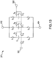
- FIG. 13 illustrates a configuration of battery module 301 according to another embodiment.
- three cells are shown for the sake of simplicity.
- switches s1-s8 and s10-s12 are used for interconnecting cells cl-c4, while switches s9 and s13 are used for cascading columns in a cluster.
- each cell can individually be disconnected from the other cells when the module is in the series arrangement. For example, if the cells are connected in series and then it is determined that cell c2 is bad, c2 can be disconnected by opening switch s8 and closing switch s11.
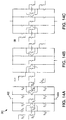
- FIGs. 14a, 14b, and 14c show an embodiment of battery module 301 that is similar to the embodiment shown in FIG. 3 .
- One difference is that there are no middle cells and the cells that are used have higher current capacity than the cells used in the embodiment shown in FIG. 3 .
- This embodiment illustrates that the same chip used in the battery module shown in FIG. 3 can be re-used to implement other configurations.
- FIG. 3 shows that the example battery pack includes only two clusters, a batter pack according to other embodiments may have more clusters.
- FIG. 3 shows that the example battery pack includes only two columns per cluster and three battery modules 301 per column, other embodiments may have other configurations.
- FIG. 9 shows an embodiment of battery pack 104 that includes N clusters of battery modules, where each cluster includes B columns of battery modules, where each column includes M battery modules, for a total of NxBxM battery modules.
- Each battery pack can be designed with different parameters of C, M, B and N, thus best matching the need of the specific car or manufacturing line.
- each cluster is connected in parallel with each other cluster.
- the columns of the cluster may be connected in parallel or in series.
- the battery modules of the column are capable of being connected in series.
- An advantage of this structure is the ability to limit the current that is passing through each Power FET within the battery module to 1xI, where I is the maximum current supported in the specific design. This means that in any configuration of the switching controls of the battery module the aggregation of the current is done by the special wiring structure outside of the battery module itself, enabling a cost effective solution.
- this structure enable the connection of C x B x N cells in parallel providing maximum current of I x (C x B x N) to be drown out of all the cells and with the change of controls it enables the connection of C x M x B cells in series, reaching V x (C x M x B) volts.
- the cascading of the columns within each cluster is enabled by the arrangement of switches that are used to interconnect the battery modules (see FIG. 3 ). This ability to draw high current and reach very high voltage enables the manufacturer of the car to reach better care performance without the limitations of fixed battery structure and is the outcome of the constellation of the switching elements within the battery module together with the specific routing design of the 3D Battery Switching GridTM outside the battery module.
- FIG. 10 is a block diagram of an example battery module 301 according to some embodiments.
- the battery module 301 includes (a) a chip 1002 containing switches and control circuitry and (b) a module of cells 1004 (in this example the module of cells includes four cells, other configurations are possible, such as 8 cells, which has been found to be a cost effective number of cells).
- the example chip 1002 shown in FIG. 10 is comprised of an analog and a digital part.
- the analog part is built out of Power MOSFETs that are arranged in the special constellation as described above.
- the number of switches e.g., Power MOSFETs
- a communication module that is capable of receiving switching commands from the EVProcessorTM in an error-resilient fashion to meet the car safety standards.
- This module is built out of a master (e.g., transmitter) and a slave (e.g., receiver) to enable a serial transfer of commands between one battery module to the other and by that minimize the number of wires transferring the switching commands within the battery pack.
- the slave communication unit of a switcher chip 1002 receives switching information from the master communication unit of an upstream switcher chip 1002, (ii) selects the switching information that is addressed to it, and (iii) transfers to the next chip in the communication chain trough the master communication unit the remainder of the switching information that it received from the upstream chip.
- the battery modules may be configured in a daisy chain arrangement where one of the battery modules is configured to receive switching information from an outside controller and then pass some, none or all of that switching information to the next battery module in the communication chain, which module then does the same thing for the next battery module in the chain, etc.
- a command decoder checks the received command to eliminate possible functional errors that might create improper switching situation within the battery module or on a larger scale in the module or pack and translates the command for the switching control logic.
- the switching control logic breaks the switching orders into actual on-off orders for each of the switching elements within the battery module.
- the safety switching sequencer receives the on-off commands for each of the switches and determines the exact sequence and timing in which each of the Power FETs needs to be switched. It takes into consideration the speed of the switching element, energy consumption during the switching sequence and of curse safety reasons - not to short any of the cells or create even momentarily an imbalance structure within the module or pack.
- FIG. 11 is a functional block diagram of such proposed EVProcessorTM 106.
- the EVProcessorTM is based on a processing device that can run sophisticated algorithms and make use of various different accelerators that optimally match the computational tasks needed in order to utilize the EV battery efficiently by the electric engine and to enable more longevity and safety.
- the EVProcessorTM implements control and "wear-out” algorithms enabling to manage each of the cells within the battery modules.
- This innovative way of managing the battery cells will increase the energy efficiency of the battery enabling longer car distance drive and decrease the cost of the battery.
- the solution will also increase the safety usage of the battery by disconnecting malfunctioning individual cells from the pack without the need to stop the car and will decrease the type-2 errors of "faulty state of charge” from the same reason.
- SmartLoadTM is an element which manages individual cells at all conditions and significantly improves battery pack performance
- DynamicPowerTM is a vehicle-system fed component that is designed to deliver voltage and current conditions matching the current specific engine needs in optimum fashion to the EV's inverter 1202 (see FIG 12 ).
- DynamicPowerTM is a standalone battery system booster that outsmarts existing EV batteries by handling cells individually, rather than the battery pack as a whole
- DynamicPowerTM requires integration with carmakers and presents, beyond energy savings, an increased driving performance with simplified and cheaper inverter 1202.
- the EVProcessorTM can sense the battery cells by means of analog or digital inputs, it can manage the cells switching grid (i.e., the switches within pack 104) using the digital outputs, it can connect to additional devices trough the scalability port, it can make use of its internal memory and Flash to hold the battery history and statistics for each cell and can extend this DB to an external memory. It can also connect to external engines through its specific bus and can communicate with the car main controller or other devices by means of wired or wireless connections to manage battery storage for instance.
- the ability to change the structure of the battery on-the-fly and in a dynamic manner that best matches the environmental and engine changing needs and that can compensate different time degradation effects and malfunctions of part of the cells redefines the battery specification and largely affect the ability to use it in different scenarios with changing parameters and environments especially cover for temperature changes.
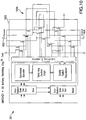
- FIG. 12 illustrates an example EV power train system 1200 that includes an embodiment of battery pack system 100 described herein.
- system 1200 includes a motor 1204 connected to an inverter 1202 that is electrically connected to the output terminals of battery pack 104, thereby receiving current output from battery pack 104.
- System 1200 also includes a main controller 1206 and a bus 1208 that allows the components to communicate.
- EVProcessorTM can use bus to obtain data from main controller and to provide commands to battery modules 301 within battery pack 104.
- the EVProcessorTM can also reside inside the battery pack 104 or as part of the main controller 1206 in the form of control-software and algorithms.
- the EVProcessorTM reads the current engine speed, determines the best appropriate voltage for that speed, and calculates the number of series cells needed to supply the best appropriate voltage. This can be done by utilizing the engine manufacturing information that specifies the best appropriate voltage per each speed. It than reads a cell history database and reviews the amount of usage cycles of each cell. The processor also read the current voltage of each cell and decides for the coming period of time which of the cells will be used and how many cells will be connected in serial and in parallel.
- the use of many micro-cells instead of large cells enables the processor to control the battery voltage in fine granularity and if a certain cell is malfunctioning and kept aside the overall effect on the battery capacity is negligible.
- the battery manufacturer can than specify less redundant cells within the battery structure because it can use less serial constantly connected cells and this additional cells can support the parallel structure instead to provide for the needed peak current.
- the EVProcessorTM reads the current engine speed and calculates the amount of series cells needed to supply the best appropriate voltage. It than reads the cell history database and review the amount of usage cycles of each cell. The processor also read the actual voltage of each cell that is with respect to the current ambient temperature and decides for the coming period of time which of the cells will be used and how many cells will be connected in serial and in parallel.
- the EVProcessorTM reads the actual voltage of each cell and the cell history database to review the amount of charge cycles the cell have already passed. It than decides for the coming period of charge time which of the cells will be charged and how many cells will be connected in serial and in parallel in order to create the best charge current flow. Cells that reach the maximum voltage allowed are kept aside while other cells charge continues. This enables charge of all of the cells to their maximum capacity. In this manner the full capacity of the battery can be used.
- the outcome of this charge process is that cells that don't need to be charged are kept out of the charging chain and are not worn-out by unnecessary charges. These cells are also less exposed to over-charge situation thus the battery usage is much safer.
- the overall charge time can be reduced in the factor of N because of charging more cells in parallel and even utilize charge in lower charge current per cell, extending the life cycle of the battery.
- the battery manufacturer can then specify less cells within the battery structure because it can use less serial constantly connected cells that overcome the ware-out problem and this additional cells can support the parallel structure instead to provide for the needed peak current.
- the EVProcessorTM reads the actual voltage of each cell. It then decides for the coming period of charge time which of the cells will be discharged and how many cells will be connected in serial and in parallel in order to create the best discharge current flow. Cells that reach the minimum voltage of 2.5V allowed are kept aside (i.e., electrically disconnected as described above) while other cells discharge continues. This enables the discharge of all of the cells to their minimum capacity. In this manner the full capacity of the battery can be used.
- the EVProcessorTM reads the car manufacturer engine graph that is stored in the database and the actual voltage of each cell and as well as the cell history database to review the amount of charge cycles the cell have already passed. It than decides for the coming period of time which of the cells will be used and how many cells will be connected in serial and in parallel in order to create the best structure to support the needed motor voltage and current. This way of using the cells in a flexible structure give the manufacturer a new degree of freedom in the design of the battery structure and support better motor values of torque and horse power providing a better car to the customer for the same battery cost.
- the battery manufacturer can also specify fewer cells within the battery structure because it can use different cell structure to support the extreme current or voltage needs in different period of time.
- the EVProcessorTM can replace most of the functionality of the Inverter by creating the desired AC power by constantly changing the amount of serial cells connected together to create the momentarily voltage.
- battery pack system 100 can be used for different battery applications like mobile phones or laptop computers.
- economy of each use-case is different but the basic practice in which we divide the battery to cells, connect them with the 3D Battery Switching GridTM battery switching grid and employ sophisticated micro-management and control methods can be matched to every case.
Landscapes
- Engineering & Computer Science (AREA)
- Power Engineering (AREA)
- Manufacturing & Machinery (AREA)
- General Chemical & Material Sciences (AREA)
- Electrochemistry (AREA)
- Chemical Kinetics & Catalysis (AREA)
- Chemical & Material Sciences (AREA)
- Sustainable Energy (AREA)
- Mechanical Engineering (AREA)
- Transportation (AREA)
- Sustainable Development (AREA)
- Life Sciences & Earth Sciences (AREA)
- Microelectronics & Electronic Packaging (AREA)
- Charge And Discharge Circuits For Batteries Or The Like (AREA)
- Secondary Cells (AREA)
- Battery Mounting, Suspending (AREA)
- Electric Propulsion And Braking For Vehicles (AREA)
Applications Claiming Priority (3)
| Application Number | Priority Date | Filing Date | Title |
|---|---|---|---|
| US201161453661P | 2011-03-17 | 2011-03-17 | |
| US201161504459P | 2011-07-05 | 2011-07-05 | |
| PCT/IB2012/000529 WO2012123815A1 (en) | 2011-03-17 | 2012-03-19 | Battery pack system |
Publications (2)
| Publication Number | Publication Date |
|---|---|
| EP2684243A1 EP2684243A1 (en) | 2014-01-15 |
| EP2684243B1 true EP2684243B1 (en) | 2019-08-21 |
Family
ID=46830098
Family Applications (1)
| Application Number | Title | Priority Date | Filing Date |
|---|---|---|---|
| EP12711691.1A Active EP2684243B1 (en) | 2011-03-17 | 2012-03-19 | Battery pack system |
Country Status (9)
| Country | Link |
|---|---|
| US (3) | US9172254B2 (enExample) |
| EP (1) | EP2684243B1 (enExample) |
| JP (1) | JP6038822B2 (enExample) |
| KR (1) | KR101821334B1 (enExample) |
| CN (1) | CN103534859B (enExample) |
| BR (1) | BR112013023584A2 (enExample) |
| CA (1) | CA2830320A1 (enExample) |
| IL (1) | IL228479B (enExample) |
| WO (1) | WO2012123815A1 (enExample) |
Families Citing this family (102)
| Publication number | Priority date | Publication date | Assignee | Title |
|---|---|---|---|---|
| FR2977986B1 (fr) * | 2011-07-13 | 2014-04-25 | Commissariat Energie Atomique | Batterie avec architecture en briques disposees en serie ou en parallele |
| US9070950B2 (en) | 2012-03-26 | 2015-06-30 | Semiconductor Energy Laboratory Co., Ltd. | Power storage element, manufacturing method thereof, and power storage device |
| US10297855B2 (en) | 2012-05-29 | 2019-05-21 | Nutech Ventures | Rechargeable multi-cell battery |
| JP6223171B2 (ja) * | 2012-12-28 | 2017-11-01 | 株式会社半導体エネルギー研究所 | 蓄電装置の制御システム、蓄電システム、及び電気機器 |
| US20160036097A1 (en) * | 2013-03-12 | 2016-02-04 | D2M- Energytransit Unipessoal, LDA | Modular electrical energy storage device and its usages |
| US9365120B2 (en) * | 2013-03-29 | 2016-06-14 | Fca Us Llc | Techniques for enhanced battery pack recharging |
| EP2993483A4 (en) * | 2013-04-30 | 2016-08-10 | Aleees Eco Ark Co Ltd | POWER SUPPLY ARCHITECTURE FOR A LARGE ELECTRIC VEHICLE AND METHOD FOR CONTROLLING A SEQUENCING STABILIZATION OF BATTERY BOXES THEREFOR |
| TWI526956B (zh) * | 2013-04-30 | 2016-03-21 | 台灣立凱綠能移動股份有限公司 | 大型電動車電源架構及其電池箱輪休排序控制方法 |
| JP6895704B2 (ja) * | 2013-08-06 | 2021-06-30 | ゴゴロ インク | 単一又は複数の動力電池を使用して電気車両に電力を供給するためのシステム及び方法 |
| DE102014200336A1 (de) * | 2014-01-10 | 2015-07-16 | Robert Bosch Gmbh | Elektrochemischer Speicherverbund |
| TWI492485B (zh) * | 2014-03-05 | 2015-07-11 | 達方電子股份有限公司 | 切換電池系統中電池組態的方法 |
| KR101702824B1 (ko) * | 2014-06-10 | 2017-02-03 | 가부시키가이샤 카그라 | 축전 소자의 충전 방법 및 축전 장치 |
| WO2016009389A1 (en) * | 2014-07-16 | 2016-01-21 | Wayne State University | Balanced control strategies for interconnected heterogeneous battery systems in smart grid applications |
| DE102015200442A1 (de) | 2015-01-14 | 2016-07-14 | Robert Bosch Gmbh | Einschaltverzögerung für eigensichere Batteriezellen |
| CN104786861B (zh) * | 2015-04-15 | 2017-11-24 | 西南交通大学 | 燃料电池控制系统及其包含燃料电池控制系统的有轨电车 |
| TWI528678B (zh) | 2015-06-15 | 2016-04-01 | 澧達科技股份有限公司 | 電源系統 |
| DE102015213456A1 (de) * | 2015-07-17 | 2017-01-19 | Robert Bosch Gmbh | Zelleinheit und Verfahren zur Bestimmung eines durch eine Zelleinheit fließenden Stroms |
| US10006967B2 (en) | 2015-10-16 | 2018-06-26 | Samsung Electronics Co., Ltd. | Battery management system for predicting life of a reconfigurable battery pack |
| JP6582909B2 (ja) | 2015-11-17 | 2019-10-02 | オムロン株式会社 | バッテリ予約装置およびバッテリ予約方法 |
| JP6766343B2 (ja) | 2015-11-17 | 2020-10-14 | オムロン株式会社 | バッテリ予約装置 |
| JP6724343B2 (ja) * | 2015-11-17 | 2020-07-15 | オムロン株式会社 | 予約管理装置、予約管理システムおよび予約管理方法 |
| JP6597218B2 (ja) | 2015-11-17 | 2019-10-30 | オムロン株式会社 | バッテリ予約装置およびバッテリ予約方法 |
| WO2017114802A1 (en) * | 2015-12-29 | 2017-07-06 | Vito Nv | Device and method for the reconfiguration of a rechargeable energy storage device into separate battery connection strings |
| CN105490350B (zh) * | 2016-01-20 | 2018-10-26 | 慈松 | 一种模块化电池网络系统和模块化电池网络系统管理方法 |
| US10305296B2 (en) * | 2016-03-04 | 2019-05-28 | Hamilton Sundstrand Corporation | Intelligent battery self repair |
| JP6677033B2 (ja) * | 2016-03-17 | 2020-04-08 | トヨタ自動車株式会社 | 電池制御システム |
| US10483791B2 (en) | 2016-05-25 | 2019-11-19 | Milwaukee Electric Tool Corporation | Series-connected battery packs, system and method |
| CN106627190A (zh) * | 2016-08-12 | 2017-05-10 | 上海鼎研智能科技有限公司 | 一种具有多个独立电池组的电动汽车 |
| KR102599399B1 (ko) * | 2016-11-04 | 2023-11-08 | 한국전력공사 | 배터리 시스템 관리 장치 및 이의 동작 방법 |
| US10305312B2 (en) * | 2016-11-08 | 2019-05-28 | Lenovo (Singapore) Pte. Ltd. | Supplemental power system for battery powered device |
| CN106696748B (zh) * | 2017-01-25 | 2019-06-28 | 华为技术有限公司 | 一种充电桩系统 |
| CN108400623B (zh) * | 2017-02-08 | 2023-01-10 | 中兴通讯股份有限公司 | 一种终端及其实现多路径供电管理的方法 |
| US10236802B2 (en) * | 2017-02-08 | 2019-03-19 | Premergy, Inc. | Adaptive regeneration systems for electric vehicles |
| DE102017106017A1 (de) * | 2017-03-21 | 2018-09-27 | HELLA GmbH & Co. KGaA | Zweispannungsbatterie |
| WO2018194684A1 (en) * | 2017-04-21 | 2018-10-25 | Hewlett-Packard Development Company, L.P. | Efficiency based battery configurations |
| KR102150147B1 (ko) * | 2017-05-24 | 2020-09-01 | 주식회사 엘지화학 | 배터리 모듈 균등화 장치 및 방법 |
| UA127478C2 (uk) | 2017-06-12 | 2023-09-06 | Тае Текнолоджиз, Інк. | Багаторівневі багатоквадрантні гістерезисні контролери струму і способи керування ними |
| MX2019015144A (es) | 2017-06-16 | 2020-02-17 | Tae Tech Inc | Controladores de voltaje de histeresis de multi nivel, para moduladores de voltaje y metodos para controlar el mismo. |
| JP2019054677A (ja) * | 2017-09-19 | 2019-04-04 | トヨタ自動車株式会社 | 電源装置 |
| CN109586349B (zh) * | 2017-09-29 | 2021-04-20 | 比亚迪股份有限公司 | 电动车辆及其充电控制装置和方法 |
| DE102017222192A1 (de) * | 2017-12-07 | 2019-06-13 | Audi Ag | HV-Batterieanordnung für ein Kraftfahrzeug, Bordnetz, Kraftfahrzeug und Verfahren zum Steuern einer HV-Batterieanordnung |
| DE102018102211B3 (de) * | 2018-02-01 | 2019-09-19 | Dr. Ing. H.C. F. Porsche Aktiengesellschaft | Batteriesystem für ein batteriebetriebenes elektrisches Fahrzeug und Verfahren zum Nutzen einer Restreichweite eines solchen |
| US12074298B2 (en) | 2018-03-19 | 2024-08-27 | EVchip Energy Ltd. | Power pack and power pack circuitry |
| DE102018106305B4 (de) * | 2018-03-19 | 2020-06-25 | Dr. Ing. H.C. F. Porsche Aktiengesellschaft | Wechselstromladung einer intelligenten Batterie |
| DE102018106304A1 (de) * | 2018-03-19 | 2019-09-19 | Dr. Ing. H.C. F. Porsche Aktiengesellschaft | Gleichstromladung einer intelligenten Batterie |
| DE102018106308B4 (de) * | 2018-03-19 | 2020-02-13 | Dr. Ing. H.C. F. Porsche Aktiengesellschaft | Modulationsindexverbesserung durch intelligente Batterie |
| EP3768543A4 (en) | 2018-03-22 | 2022-01-05 | TAE Technologies, Inc. | ENERGY MANAGEMENT AND CONTROL SYSTEMS AND PROCESSES |
| DE102018206096A1 (de) | 2018-04-20 | 2019-10-24 | Audi Ag | Batteriesystem und Verfahren zum Betreiben eines Batteriesystems |
| WO2019214824A1 (en) * | 2018-05-09 | 2019-11-14 | Byton Limited | Flexibly configurable traction battery |
| CN110635177B (zh) | 2018-06-22 | 2021-05-11 | 华为技术有限公司 | 电池控制方法、电池控制装置以及计算机可读存储介质 |
| JPWO2019243950A1 (ja) | 2018-06-22 | 2021-07-26 | 株式会社半導体エネルギー研究所 | 蓄電装置の異常検知方法、及び蓄電装置の制御装置 |
| US10892469B2 (en) * | 2018-07-30 | 2021-01-12 | International Business Machines Corporation | Safety compliant battery cell ejection for packaged battery cells |
| US10596917B2 (en) * | 2018-08-14 | 2020-03-24 | GM Global Technology Operations LLC | Vehicle and electrical system with dual battery modules |
| US10714736B2 (en) * | 2018-08-29 | 2020-07-14 | International Business Machines Corporation | Battery pack system with integrated battery disconnect mechanism |
| WO2020077126A1 (en) * | 2018-10-12 | 2020-04-16 | Briggs & Stratton Corporation | Battery packs with cell module assemblies usable in multiple applications |
| US11677260B2 (en) | 2018-10-22 | 2023-06-13 | O2Micro Inc. | Managing power in a portable device comprising multiple batteries |
| GB2578828B (en) * | 2018-10-22 | 2021-03-10 | O2Micro Inc | Managing power in a portable device comprising multiple batteries |
| JP6973857B2 (ja) * | 2018-12-03 | 2021-12-01 | Necプラットフォームズ株式会社 | バッテリ制御システム、バッテリ装置、コンピュータ装置、バッテリ制御方法及びプログラム |
| CN109591625A (zh) * | 2018-12-07 | 2019-04-09 | 江西洪都航空工业集团有限责任公司 | 一种无人车的冗余电源供电控制方法 |
| GB2580373B (en) * | 2019-01-07 | 2021-04-28 | Tanktwo Oy | Modular battery system |
| WO2020153866A1 (en) * | 2019-01-24 | 2020-07-30 | Siemens Aktiengesellschaft | Method and system for monitoring a battery state using a battery twin |
| CN109649191A (zh) * | 2019-01-30 | 2019-04-19 | 哈尔滨格瑞赛科新能源有限公司 | 一种电动汽车动力电池系统 |
| US10800285B2 (en) * | 2019-03-01 | 2020-10-13 | GM Global Technology Operations LLC | System to modulate switch resistances within a battery system |
| KR20210141716A (ko) | 2019-03-29 | 2021-11-23 | 티에이이 테크놀로지스, 인크. | 종속 접속되고 상호 접속된 구성들이 가능한 모듈 기반 에너지 시스템들 및 이에 관련된 방법 |
| US11340300B2 (en) | 2019-04-05 | 2022-05-24 | Samsung Electronics Co., Ltd. | Battery service life management method and system |
| CN110350625A (zh) * | 2019-07-28 | 2019-10-18 | 王京 | 一种储能系统及其控制方法 |
| CN110562095A (zh) * | 2019-08-14 | 2019-12-13 | 珠海凯邦电机制造有限公司 | 电动汽车、电池电压调节电路及方法 |
| JP7347048B2 (ja) * | 2019-09-12 | 2023-09-20 | 株式会社豊田自動織機 | 接続回路及び二次電池システム |
| DE102019130736A1 (de) * | 2019-11-14 | 2021-05-20 | Audi Ag | Batterie mit einem Batteriemodul und Verfahren zu deren Betrieb |
| JP7415145B2 (ja) * | 2019-12-16 | 2024-01-17 | 株式会社今仙電機製作所 | 車両用電源装置 |
| DE102020108053A1 (de) * | 2020-03-24 | 2021-09-30 | Voith Patent Gmbh | Redox-Flow-Batterie-System und Betriebsverfahren |
| US11897347B2 (en) | 2020-04-14 | 2024-02-13 | Tae Technologies, Inc. | Systems, devices, and methods for charging and discharging module-based cascaded energy systems |
| AU2021254739A1 (en) | 2020-04-14 | 2022-12-01 | Tae Technologies, Inc. | Modular cascaded energy systems with a cooling apparatus and with replaceable energy source capability |
| CN111585334A (zh) * | 2020-04-23 | 2020-08-25 | 苏州市职业大学 | 一种光伏供电系统 |
| MX2022014260A (es) | 2020-05-14 | 2023-02-22 | Tae Tech Inc | Sistemas, dispositivos y métodos para vehículos eléctricos basados en raíles y otros con sistemas modulares de energía en cascada. |
| KR102409518B1 (ko) | 2020-06-22 | 2022-06-17 | 조은바이오주식회사 | 대량의 하천수를 저장하여 인공양어장을 조성함과 동시에 미세먼지 발생량을 줄여주도록 유도시켜서 대기중의 오염된 공기를 개선시킴과 동시에 비중이 무거운 깨끗한 물 분자를 우선적으로 배출하여 오염된 하천수를 깨끗한 하천수로 정화시키도록 구성되는 자연친화적인 친환경 저수시스템을 이용하여 대량의 전기를 생산하면서 저수지, 호수,댐, 석호,하천,강의 수질을 자연정화시키는 자연친화적인 수질정화 친환경공법 |
| DE102020118418A1 (de) | 2020-07-13 | 2022-01-13 | Duesenfeld Gmbh | Akkumulator-Entladevorrichtung zum Entladen von Akkumulatoren und Verfahren zum Entladen einer Mehrzahl an Akkumulatoren |
| US20240359595A1 (en) * | 2020-08-24 | 2024-10-31 | Tae Technologies, Inc. | Modular Cascaded Energy Systems with a Cooling Apparatus and with Replaceable Energy Source Capability |
| CN112092675B (zh) * | 2020-08-31 | 2022-03-25 | 长城汽车股份有限公司 | 一种电池热失控预警方法、系统及服务器 |
| KR20230074240A (ko) | 2020-09-28 | 2023-05-26 | 티에이이 테크놀로지스, 인크. | 다상 모듈 기반의 에너지 시스템 프레임워크 및 그것에 관련되는 방법 |
| CA3197315A1 (en) | 2020-09-30 | 2022-04-07 | Tae Technologies, Inc. | Systems, devices, and methods for intraphase and interphase balancing in module-based cascaded energy systems |
| DE102020214506A1 (de) | 2020-11-18 | 2022-05-19 | Robert Bosch Gesellschaft mit beschränkter Haftung | Batteriemodul für eine Antriebsbatterie und Antriebsbatterie mit mehreren Batteriemodulen |
| US12002975B2 (en) | 2020-12-01 | 2024-06-04 | Caterpillar Inc. | Structural battery module and battery pack |
| CN112737018B (zh) * | 2020-12-24 | 2022-07-15 | 东莞新能安科技有限公司 | 电池包主从动态并机方法、用电设备及存储介质 |
| KR20220100332A (ko) * | 2021-01-08 | 2022-07-15 | 주식회사 엘지에너지솔루션 | 배터리 장치 및 전압 공급 방법 |
| KR20230132641A (ko) | 2021-01-13 | 2023-09-15 | 티에이이 테크놀로지스, 인크. | 모듈 기반 캐스케이드식 에너지 시스템을 위한 시스템,장치 및 방법 |
| FR3119717B1 (fr) * | 2021-02-09 | 2025-05-09 | Psa Automobiles Sa | Contrôle de la configuration d’une batterie modulaire pour éviter des situations dangereuses |
| FR3120277B1 (fr) * | 2021-02-26 | 2023-05-12 | Otonohm | Dispositif de stockage et de génération concomitante d’au moins une tension électrique, et procédé de gestion associé |
| DE102021111865A1 (de) | 2021-05-06 | 2022-11-10 | instagrid GmbH | Mobiles Energieversorgungssystem mit optimierter Energiedichte |
| US11870288B1 (en) | 2021-05-19 | 2024-01-09 | Francois Renaud-Byrne | Intelligent battery system and method of operation |
| US12036884B2 (en) * | 2021-06-17 | 2024-07-16 | GM Global Technology Operations LLC | Propulsion systems with power sources compatible with different charging stations and dynamically scalable for different vehicle speed and torque modes |
| EP4367770A4 (en) | 2021-07-07 | 2025-06-18 | TAE Technologies, Inc. | Systems, devices and methods for modular cascaded energy systems configured for coupling with renewable energy sources |
| CN114243639A (zh) * | 2021-12-10 | 2022-03-25 | 中国电子科技集团公司第二十九研究所 | 一种主辅供电分离实现超温自动保护的方法和系统 |
| CN114300764B (zh) * | 2021-12-22 | 2024-02-20 | 东莞新能安科技有限公司 | 电池模组和储能系统 |
| TWI788165B (zh) | 2021-12-28 | 2022-12-21 | 台達電子工業股份有限公司 | 電源傳輸系統及方法 |
| EP4480062A1 (en) * | 2022-02-18 | 2024-12-25 | B2U Storage Solutions Inc. | Energy storage system and method employing second-life electric vehicle batteries |
| US12451706B2 (en) * | 2022-08-03 | 2025-10-21 | GM Global Technology Operations LLC | Multi-voltage vehicle operation |
| DE102022120005A1 (de) * | 2022-08-09 | 2024-02-15 | Dr. Ing. H.C. F. Porsche Aktiengesellschaft | Verfahren und System zu einem Notfallbetrieb für einen modularen Multilevelkonverter |
| TWI837985B (zh) * | 2022-08-23 | 2024-04-01 | 財團法人Mih Ev研發院 | 動力控制系統、電池系統及其控制方法 |
| FR3149552B1 (fr) * | 2023-06-06 | 2025-10-31 | Alstom Holdings | Système de traction d’un véhicule ferroviaire et véhicule ferroviaire associé |
| CN116581403B (zh) * | 2023-07-13 | 2023-09-05 | 苏州精控能源科技有限公司 | 一种电池模组控制方法、系统以及电路 |
| DE102024105826A1 (de) * | 2024-02-29 | 2025-09-04 | Man Truck & Bus Se | Energiespeichervorrichtung mit energiespeicherübergreifend verbindbaren Zellmodulen |
Citations (1)
| Publication number | Priority date | Publication date | Assignee | Title |
|---|---|---|---|---|
| US20100261048A1 (en) * | 2009-04-10 | 2010-10-14 | The Regents Of The University Of Michigan | Dynamically reconfigurable framework for a large-scale battery system |
Family Cites Families (16)
| Publication number | Priority date | Publication date | Assignee | Title |
|---|---|---|---|---|
| JPH11234909A (ja) * | 1998-02-16 | 1999-08-27 | Nec Corp | 蓄電池を用いた電源装置 |
| US6554088B2 (en) | 1998-09-14 | 2003-04-29 | Paice Corporation | Hybrid vehicles |
| DE10055531B4 (de) * | 2000-07-04 | 2012-04-26 | Continental Teves Ag & Co. Ohg | Elektronische Schaltungsanordnung zur Spannungsversorgung in Kraftfahrzeugen, deren Verwendung und Verfahren zum Betreiben einer Spannungsversorgung |
| JP3716300B2 (ja) * | 2001-03-26 | 2005-11-16 | 独立行政法人産業技術総合研究所 | 電池有効利用回路 |
| US20060092583A1 (en) | 2004-10-01 | 2006-05-04 | Alahmad Mahmoud A | Switch array and power management system for batteries and other energy storage elements |
| US7705560B2 (en) * | 2006-08-15 | 2010-04-27 | N. P. Johnson Family Limited Partnership | Voltage controller |
| JP2008148387A (ja) | 2006-12-06 | 2008-06-26 | Matsushita Electric Ind Co Ltd | 電池パック |
| DE102007060329A1 (de) * | 2007-12-14 | 2009-07-02 | Forschungszentrum Karlsruhe Gmbh | Kondensatorenblock aus miteinander verschaltbaren Kondensatoren und Verfahren zum Be- und Entladen desselben |
| EP3017986B1 (en) | 2008-06-27 | 2022-11-09 | Proterra Operating Company, Inc. | Vehicle battery systems and method |
| US8110300B2 (en) | 2008-06-30 | 2012-02-07 | Lg Chem, Ltd. | Battery mounting system |
| JP5321080B2 (ja) * | 2009-01-20 | 2013-10-23 | 日産自動車株式会社 | 電力供給装置 |
| WO2010118310A2 (en) * | 2009-04-10 | 2010-10-14 | The Regents Of The University Of Michigan | Dynamically reconfigurable framework for a large-scale battery system |
| JP2011050208A (ja) | 2009-08-28 | 2011-03-10 | Japan Aerospace Exploration Agency | スイッチトキャパシタシステムの中間タップを利用した出力電圧調整装置 |
| FR2947112A1 (fr) * | 2009-10-29 | 2010-12-24 | Commissariat Energie Atomique | Dispositif de recharge d'une batterie d'accumulateurs |
| US8957624B2 (en) * | 2011-01-20 | 2015-02-17 | Valence Technology, Inc. | Rechargeable battery systems and rechargeable battery system operational methods |
| US10044074B2 (en) * | 2011-03-18 | 2018-08-07 | Johnson Controls Technology Company | Battery power source control and current detection systems and methods |
-
2012
- 2012-03-19 CA CA2830320A patent/CA2830320A1/en not_active Abandoned
- 2012-03-19 KR KR1020137027460A patent/KR101821334B1/ko active Active
- 2012-03-19 WO PCT/IB2012/000529 patent/WO2012123815A1/en not_active Ceased
- 2012-03-19 US US13/423,972 patent/US9172254B2/en active Active
- 2012-03-19 JP JP2013558524A patent/JP6038822B2/ja active Active
- 2012-03-19 CN CN201280023490.6A patent/CN103534859B/zh active Active
- 2012-03-19 EP EP12711691.1A patent/EP2684243B1/en active Active
- 2012-03-19 BR BR112013023584A patent/BR112013023584A2/pt not_active Application Discontinuation
-
2013
- 2013-09-16 IL IL228479A patent/IL228479B/en active IP Right Grant
-
2015
- 2015-10-26 US US14/923,151 patent/US10193359B2/en active Active
-
2018
- 2018-12-11 US US16/216,510 patent/US10651660B2/en active Active
Patent Citations (1)
| Publication number | Priority date | Publication date | Assignee | Title |
|---|---|---|---|---|
| US20100261048A1 (en) * | 2009-04-10 | 2010-10-14 | The Regents Of The University Of Michigan | Dynamically reconfigurable framework for a large-scale battery system |
Also Published As
| Publication number | Publication date |
|---|---|
| IL228479A0 (en) | 2013-12-31 |
| US20120274140A1 (en) | 2012-11-01 |
| US20160211680A1 (en) | 2016-07-21 |
| US9172254B2 (en) | 2015-10-27 |
| US10651660B2 (en) | 2020-05-12 |
| EP2684243A1 (en) | 2014-01-15 |
| US20190109470A1 (en) | 2019-04-11 |
| CN103534859A (zh) | 2014-01-22 |
| WO2012123815A1 (en) | 2012-09-20 |
| CA2830320A1 (en) | 2012-09-20 |
| JP6038822B2 (ja) | 2016-12-07 |
| BR112013023584A2 (pt) | 2016-12-06 |
| JP2014514899A (ja) | 2014-06-19 |
| CN103534859B (zh) | 2017-03-29 |
| KR20140024325A (ko) | 2014-02-28 |
| US10193359B2 (en) | 2019-01-29 |
| IL228479B (en) | 2018-10-31 |
| KR101821334B1 (ko) | 2018-03-08 |
Similar Documents
| Publication | Publication Date | Title |
|---|---|---|
| US10651660B2 (en) | Battery pack system | |
| EP3579327B1 (en) | Battery module equalization apparatus, and battery pack and automobile including same | |
| KR102816659B1 (ko) | 배터리 시스템 | |
| US8471529B2 (en) | Battery fault tolerant architecture for cell failure modes parallel bypass circuit | |
| US9150114B2 (en) | Storage system | |
| US8502502B2 (en) | Electricity storing device and electronic device | |
| TWI398068B (zh) | 單元化充放電之電池電源管理系統及其可程式化電池管理模組 | |
| US20130002016A1 (en) | Power source apparatus, vehicle and power storage system using the power source apparatus | |
| US20160241052A1 (en) | Battery pack and battery system including the same | |
| TW201443793A (zh) | 大型電動車電源架構及其電池箱輪休排序控制方法 | |
| KR20150013302A (ko) | 배터리의 충전 밸런싱 | |
| EP3096431B1 (en) | Battery management unit and method for setting identifier by using frequency modulation | |
| Baronti et al. | Design of the battery management system of LiFePO 4 batteries for electric off-road vehicles | |
| KR20160132633A (ko) | 배터리 시스템 및 그 연결 제어 방법 | |
| JP7459439B2 (ja) | バッテリ装置および電圧供給方法 | |
| EP3337002B1 (en) | Battery system and control unit for a battery system | |
| Lee et al. | An integrated design of active balancing and redundancy at module level for electric vehicle batteries | |
| CN117916974A (zh) | 电池设备以及平衡方法 | |
| KR20240061440A (ko) | 다중 ess 출력 제어 방법 | |
| WO2025181512A1 (en) | Active balancing of energy among batteries | |
| JP2021040421A (ja) | 蓄電素子モジュールバランス回路 | |
| JP2019213333A (ja) | 組電池監視装置 |
Legal Events
| Date | Code | Title | Description |
|---|---|---|---|
| PUAI | Public reference made under article 153(3) epc to a published international application that has entered the european phase |
Free format text: ORIGINAL CODE: 0009012 |
|
| 17P | Request for examination filed |
Effective date: 20131008 |
|
| AK | Designated contracting states |
Kind code of ref document: A1 Designated state(s): AL AT BE BG CH CY CZ DE DK EE ES FI FR GB GR HR HU IE IS IT LI LT LU LV MC MK MT NL NO PL PT RO RS SE SI SK SM TR |
|
| DAX | Request for extension of the european patent (deleted) | ||
| 17Q | First examination report despatched |
Effective date: 20160331 |
|
| STAA | Information on the status of an ep patent application or granted ep patent |
Free format text: STATUS: EXAMINATION IS IN PROGRESS |
|
| RIC1 | Information provided on ipc code assigned before grant |
Ipc: H01M 10/42 20060101AFI20181219BHEP Ipc: B60L 11/18 20060101ALI20181219BHEP Ipc: H02J 7/00 20060101ALI20181219BHEP Ipc: H01M 10/04 20060101ALI20181219BHEP |
|
| GRAP | Despatch of communication of intention to grant a patent |
Free format text: ORIGINAL CODE: EPIDOSNIGR1 |
|
| STAA | Information on the status of an ep patent application or granted ep patent |
Free format text: STATUS: GRANT OF PATENT IS INTENDED |
|
| REG | Reference to a national code |
Ref country code: DE Ref legal event code: R079 Ref document number: 602012063116 Country of ref document: DE Free format text: PREVIOUS MAIN CLASS: H01M0010040000 Ipc: H01M0010420000 |
|
| INTG | Intention to grant announced |
Effective date: 20190206 |
|
| RIC1 | Information provided on ipc code assigned before grant |
Ipc: H01M 10/42 20060101AFI20190206BHEP Ipc: H01M 10/04 20060101ALI20190206BHEP Ipc: H02J 7/00 20060101ALI20190206BHEP Ipc: B60L 50/60 20190101ALI20190206BHEP |
|
| GRAS | Grant fee paid |
Free format text: ORIGINAL CODE: EPIDOSNIGR3 |
|
| GRAJ | Information related to disapproval of communication of intention to grant by the applicant or resumption of examination proceedings by the epo deleted |
Free format text: ORIGINAL CODE: EPIDOSDIGR1 |
|
| GRAL | Information related to payment of fee for publishing/printing deleted |
Free format text: ORIGINAL CODE: EPIDOSDIGR3 |
|
| STAA | Information on the status of an ep patent application or granted ep patent |
Free format text: STATUS: EXAMINATION IS IN PROGRESS |
|
| GRAR | Information related to intention to grant a patent recorded |
Free format text: ORIGINAL CODE: EPIDOSNIGR71 |
|
| STAA | Information on the status of an ep patent application or granted ep patent |
Free format text: STATUS: GRANT OF PATENT IS INTENDED |
|
| INTC | Intention to grant announced (deleted) | ||
| GRAA | (expected) grant |
Free format text: ORIGINAL CODE: 0009210 |
|
| STAA | Information on the status of an ep patent application or granted ep patent |
Free format text: STATUS: THE PATENT HAS BEEN GRANTED |
|
| INTG | Intention to grant announced |
Effective date: 20190710 |
|
| AK | Designated contracting states |
Kind code of ref document: B1 Designated state(s): AL AT BE BG CH CY CZ DE DK EE ES FI FR GB GR HR HU IE IS IT LI LT LU LV MC MK MT NL NO PL PT RO RS SE SI SK SM TR |
|
| REG | Reference to a national code |
Ref country code: GB Ref legal event code: FG4D |
|
| REG | Reference to a national code |
Ref country code: CH Ref legal event code: EP |
|
| REG | Reference to a national code |
Ref country code: DE Ref legal event code: R096 Ref document number: 602012063116 Country of ref document: DE |
|
| REG | Reference to a national code |
Ref country code: AT Ref legal event code: REF Ref document number: 1170792 Country of ref document: AT Kind code of ref document: T Effective date: 20190915 |
|
| REG | Reference to a national code |
Ref country code: IE Ref legal event code: FG4D |
|
| REG | Reference to a national code |
Ref country code: LT Ref legal event code: MG4D |
|
| REG | Reference to a national code |
Ref country code: NL Ref legal event code: MP Effective date: 20190821 |
|
| PG25 | Lapsed in a contracting state [announced via postgrant information from national office to epo] |
Ref country code: FI Free format text: LAPSE BECAUSE OF FAILURE TO SUBMIT A TRANSLATION OF THE DESCRIPTION OR TO PAY THE FEE WITHIN THE PRESCRIBED TIME-LIMIT Effective date: 20190821 Ref country code: LT Free format text: LAPSE BECAUSE OF FAILURE TO SUBMIT A TRANSLATION OF THE DESCRIPTION OR TO PAY THE FEE WITHIN THE PRESCRIBED TIME-LIMIT Effective date: 20190821 Ref country code: HR Free format text: LAPSE BECAUSE OF FAILURE TO SUBMIT A TRANSLATION OF THE DESCRIPTION OR TO PAY THE FEE WITHIN THE PRESCRIBED TIME-LIMIT Effective date: 20190821 Ref country code: SE Free format text: LAPSE BECAUSE OF FAILURE TO SUBMIT A TRANSLATION OF THE DESCRIPTION OR TO PAY THE FEE WITHIN THE PRESCRIBED TIME-LIMIT Effective date: 20190821 Ref country code: PT Free format text: LAPSE BECAUSE OF FAILURE TO SUBMIT A TRANSLATION OF THE DESCRIPTION OR TO PAY THE FEE WITHIN THE PRESCRIBED TIME-LIMIT Effective date: 20191223 Ref country code: NO Free format text: LAPSE BECAUSE OF FAILURE TO SUBMIT A TRANSLATION OF THE DESCRIPTION OR TO PAY THE FEE WITHIN THE PRESCRIBED TIME-LIMIT Effective date: 20191121 Ref country code: BG Free format text: LAPSE BECAUSE OF FAILURE TO SUBMIT A TRANSLATION OF THE DESCRIPTION OR TO PAY THE FEE WITHIN THE PRESCRIBED TIME-LIMIT Effective date: 20191121 Ref country code: NL Free format text: LAPSE BECAUSE OF FAILURE TO SUBMIT A TRANSLATION OF THE DESCRIPTION OR TO PAY THE FEE WITHIN THE PRESCRIBED TIME-LIMIT Effective date: 20190821 |
|
| PG25 | Lapsed in a contracting state [announced via postgrant information from national office to epo] |
Ref country code: LV Free format text: LAPSE BECAUSE OF FAILURE TO SUBMIT A TRANSLATION OF THE DESCRIPTION OR TO PAY THE FEE WITHIN THE PRESCRIBED TIME-LIMIT Effective date: 20190821 Ref country code: ES Free format text: LAPSE BECAUSE OF FAILURE TO SUBMIT A TRANSLATION OF THE DESCRIPTION OR TO PAY THE FEE WITHIN THE PRESCRIBED TIME-LIMIT Effective date: 20190821 Ref country code: AL Free format text: LAPSE BECAUSE OF FAILURE TO SUBMIT A TRANSLATION OF THE DESCRIPTION OR TO PAY THE FEE WITHIN THE PRESCRIBED TIME-LIMIT Effective date: 20190821 Ref country code: GR Free format text: LAPSE BECAUSE OF FAILURE TO SUBMIT A TRANSLATION OF THE DESCRIPTION OR TO PAY THE FEE WITHIN THE PRESCRIBED TIME-LIMIT Effective date: 20191122 Ref country code: IS Free format text: LAPSE BECAUSE OF FAILURE TO SUBMIT A TRANSLATION OF THE DESCRIPTION OR TO PAY THE FEE WITHIN THE PRESCRIBED TIME-LIMIT Effective date: 20191221 Ref country code: RS Free format text: LAPSE BECAUSE OF FAILURE TO SUBMIT A TRANSLATION OF THE DESCRIPTION OR TO PAY THE FEE WITHIN THE PRESCRIBED TIME-LIMIT Effective date: 20190821 |
|
| REG | Reference to a national code |
Ref country code: AT Ref legal event code: MK05 Ref document number: 1170792 Country of ref document: AT Kind code of ref document: T Effective date: 20190821 |
|
| PG25 | Lapsed in a contracting state [announced via postgrant information from national office to epo] |
Ref country code: TR Free format text: LAPSE BECAUSE OF FAILURE TO SUBMIT A TRANSLATION OF THE DESCRIPTION OR TO PAY THE FEE WITHIN THE PRESCRIBED TIME-LIMIT Effective date: 20190821 |
|
| PG25 | Lapsed in a contracting state [announced via postgrant information from national office to epo] |
Ref country code: EE Free format text: LAPSE BECAUSE OF FAILURE TO SUBMIT A TRANSLATION OF THE DESCRIPTION OR TO PAY THE FEE WITHIN THE PRESCRIBED TIME-LIMIT Effective date: 20190821 Ref country code: PL Free format text: LAPSE BECAUSE OF FAILURE TO SUBMIT A TRANSLATION OF THE DESCRIPTION OR TO PAY THE FEE WITHIN THE PRESCRIBED TIME-LIMIT Effective date: 20190821 Ref country code: AT Free format text: LAPSE BECAUSE OF FAILURE TO SUBMIT A TRANSLATION OF THE DESCRIPTION OR TO PAY THE FEE WITHIN THE PRESCRIBED TIME-LIMIT Effective date: 20190821 Ref country code: IT Free format text: LAPSE BECAUSE OF FAILURE TO SUBMIT A TRANSLATION OF THE DESCRIPTION OR TO PAY THE FEE WITHIN THE PRESCRIBED TIME-LIMIT Effective date: 20190821 Ref country code: RO Free format text: LAPSE BECAUSE OF FAILURE TO SUBMIT A TRANSLATION OF THE DESCRIPTION OR TO PAY THE FEE WITHIN THE PRESCRIBED TIME-LIMIT Effective date: 20190821 Ref country code: DK Free format text: LAPSE BECAUSE OF FAILURE TO SUBMIT A TRANSLATION OF THE DESCRIPTION OR TO PAY THE FEE WITHIN THE PRESCRIBED TIME-LIMIT Effective date: 20190821 |
|
| PG25 | Lapsed in a contracting state [announced via postgrant information from national office to epo] |
Ref country code: SK Free format text: LAPSE BECAUSE OF FAILURE TO SUBMIT A TRANSLATION OF THE DESCRIPTION OR TO PAY THE FEE WITHIN THE PRESCRIBED TIME-LIMIT Effective date: 20190821 Ref country code: SM Free format text: LAPSE BECAUSE OF FAILURE TO SUBMIT A TRANSLATION OF THE DESCRIPTION OR TO PAY THE FEE WITHIN THE PRESCRIBED TIME-LIMIT Effective date: 20190821 Ref country code: IS Free format text: LAPSE BECAUSE OF FAILURE TO SUBMIT A TRANSLATION OF THE DESCRIPTION OR TO PAY THE FEE WITHIN THE PRESCRIBED TIME-LIMIT Effective date: 20200224 Ref country code: CZ Free format text: LAPSE BECAUSE OF FAILURE TO SUBMIT A TRANSLATION OF THE DESCRIPTION OR TO PAY THE FEE WITHIN THE PRESCRIBED TIME-LIMIT Effective date: 20190821 |
|
| REG | Reference to a national code |
Ref country code: DE Ref legal event code: R097 Ref document number: 602012063116 Country of ref document: DE |
|
| PLBE | No opposition filed within time limit |
Free format text: ORIGINAL CODE: 0009261 |
|
| STAA | Information on the status of an ep patent application or granted ep patent |
Free format text: STATUS: NO OPPOSITION FILED WITHIN TIME LIMIT |
|
| PG2D | Information on lapse in contracting state deleted |
Ref country code: IS |
|
| 26N | No opposition filed |
Effective date: 20200603 |
|
| PG25 | Lapsed in a contracting state [announced via postgrant information from national office to epo] |
Ref country code: SI Free format text: LAPSE BECAUSE OF FAILURE TO SUBMIT A TRANSLATION OF THE DESCRIPTION OR TO PAY THE FEE WITHIN THE PRESCRIBED TIME-LIMIT Effective date: 20190821 |
|
| PG25 | Lapsed in a contracting state [announced via postgrant information from national office to epo] |
Ref country code: MC Free format text: LAPSE BECAUSE OF FAILURE TO SUBMIT A TRANSLATION OF THE DESCRIPTION OR TO PAY THE FEE WITHIN THE PRESCRIBED TIME-LIMIT Effective date: 20190821 |
|
| REG | Reference to a national code |
Ref country code: CH Ref legal event code: PL |
|
| REG | Reference to a national code |
Ref country code: BE Ref legal event code: MM Effective date: 20200331 |
|
| PG25 | Lapsed in a contracting state [announced via postgrant information from national office to epo] |
Ref country code: LU Free format text: LAPSE BECAUSE OF NON-PAYMENT OF DUE FEES Effective date: 20200319 |
|
| PG25 | Lapsed in a contracting state [announced via postgrant information from national office to epo] |
Ref country code: LI Free format text: LAPSE BECAUSE OF NON-PAYMENT OF DUE FEES Effective date: 20200331 Ref country code: CH Free format text: LAPSE BECAUSE OF NON-PAYMENT OF DUE FEES Effective date: 20200331 Ref country code: IE Free format text: LAPSE BECAUSE OF NON-PAYMENT OF DUE FEES Effective date: 20200319 |
|
| PG25 | Lapsed in a contracting state [announced via postgrant information from national office to epo] |
Ref country code: BE Free format text: LAPSE BECAUSE OF NON-PAYMENT OF DUE FEES Effective date: 20200331 |
|
| PG25 | Lapsed in a contracting state [announced via postgrant information from national office to epo] |
Ref country code: MT Free format text: LAPSE BECAUSE OF FAILURE TO SUBMIT A TRANSLATION OF THE DESCRIPTION OR TO PAY THE FEE WITHIN THE PRESCRIBED TIME-LIMIT Effective date: 20190821 Ref country code: CY Free format text: LAPSE BECAUSE OF FAILURE TO SUBMIT A TRANSLATION OF THE DESCRIPTION OR TO PAY THE FEE WITHIN THE PRESCRIBED TIME-LIMIT Effective date: 20190821 |
|
| PG25 | Lapsed in a contracting state [announced via postgrant information from national office to epo] |
Ref country code: MK Free format text: LAPSE BECAUSE OF FAILURE TO SUBMIT A TRANSLATION OF THE DESCRIPTION OR TO PAY THE FEE WITHIN THE PRESCRIBED TIME-LIMIT Effective date: 20190821 |
|
| PGFP | Annual fee paid to national office [announced via postgrant information from national office to epo] |
Ref country code: DE Payment date: 20240124 Year of fee payment: 13 Ref country code: GB Payment date: 20240125 Year of fee payment: 13 |
|
| PGFP | Annual fee paid to national office [announced via postgrant information from national office to epo] |
Ref country code: FR Payment date: 20240111 Year of fee payment: 13 |
|
| REG | Reference to a national code |
Ref country code: DE Ref legal event code: R119 Ref document number: 602012063116 Country of ref document: DE |
|
| GBPC | Gb: european patent ceased through non-payment of renewal fee |
Effective date: 20250319 |