EP2682732A1 - Système de contrôle d'état pour dispositif de roulement et procédé de contrôle d'état - Google Patents
Système de contrôle d'état pour dispositif de roulement et procédé de contrôle d'état Download PDFInfo
- Publication number
- EP2682732A1 EP2682732A1 EP12751866.0A EP12751866A EP2682732A1 EP 2682732 A1 EP2682732 A1 EP 2682732A1 EP 12751866 A EP12751866 A EP 12751866A EP 2682732 A1 EP2682732 A1 EP 2682732A1
- Authority
- EP
- European Patent Office
- Prior art keywords
- water concentration
- rolling
- threshold value
- contaminant water
- abnormality
- Prior art date
- Legal status (The legal status is an assumption and is not a legal conclusion. Google has not performed a legal analysis and makes no representation as to the accuracy of the status listed.)
- Granted
Links
- 238000005096 rolling process Methods 0.000 title claims abstract description 400
- 238000012544 monitoring process Methods 0.000 title claims abstract description 192
- 238000000034 method Methods 0.000 title claims description 74
- XLYOFNOQVPJJNP-UHFFFAOYSA-N water Substances O XLYOFNOQVPJJNP-UHFFFAOYSA-N 0.000 claims abstract description 461
- 239000000356 contaminant Substances 0.000 claims abstract description 271
- 239000000314 lubricant Substances 0.000 claims abstract description 206
- 238000004364 calculation method Methods 0.000 claims abstract description 96
- 238000012806 monitoring device Methods 0.000 claims abstract description 16
- 230000005856 abnormality Effects 0.000 claims description 251
- 238000012360 testing method Methods 0.000 claims description 208
- 230000009467 reduction Effects 0.000 claims description 105
- 238000005259 measurement Methods 0.000 claims description 69
- 230000007246 mechanism Effects 0.000 claims description 56
- 238000003745 diagnosis Methods 0.000 claims description 53
- 229910000831 Steel Inorganic materials 0.000 claims description 45
- 239000010959 steel Substances 0.000 claims description 45
- 238000005461 lubrication Methods 0.000 claims description 40
- 238000006073 displacement reaction Methods 0.000 claims description 39
- 238000012545 processing Methods 0.000 claims description 35
- 239000000463 material Substances 0.000 claims description 32
- 230000008859 change Effects 0.000 claims description 31
- 230000008569 process Effects 0.000 claims description 21
- 238000005299 abrasion Methods 0.000 claims description 20
- 238000005336 cracking Methods 0.000 claims description 16
- 239000012535 impurity Substances 0.000 claims description 16
- 230000001133 acceleration Effects 0.000 claims description 13
- 239000000654 additive Substances 0.000 claims description 13
- 238000009661 fatigue test Methods 0.000 claims description 11
- 230000000996 additive effect Effects 0.000 claims description 10
- 238000003756 stirring Methods 0.000 claims description 8
- 229910010293 ceramic material Inorganic materials 0.000 claims description 7
- 230000005484 gravity Effects 0.000 claims description 7
- 239000000843 powder Substances 0.000 claims description 4
- 239000003921 oil Substances 0.000 description 339
- 239000001257 hydrogen Substances 0.000 description 53
- 229910052739 hydrogen Inorganic materials 0.000 description 53
- UFHFLCQGNIYNRP-UHFFFAOYSA-N Hydrogen Chemical compound [H][H] UFHFLCQGNIYNRP-UHFFFAOYSA-N 0.000 description 46
- 230000006870 function Effects 0.000 description 45
- 238000010586 diagram Methods 0.000 description 44
- 238000004299 exfoliation Methods 0.000 description 39
- 238000004458 analytical method Methods 0.000 description 37
- 238000010276 construction Methods 0.000 description 34
- 238000004088 simulation Methods 0.000 description 31
- 238000001514 detection method Methods 0.000 description 29
- 230000000694 effects Effects 0.000 description 23
- 238000004891 communication Methods 0.000 description 22
- 229920006395 saturated elastomer Polymers 0.000 description 20
- XEEYBQQBJWHFJM-UHFFFAOYSA-N Iron Chemical compound [Fe] XEEYBQQBJWHFJM-UHFFFAOYSA-N 0.000 description 19
- 238000003860 storage Methods 0.000 description 19
- 230000002028 premature Effects 0.000 description 13
- 230000001050 lubricating effect Effects 0.000 description 12
- 238000002156 mixing Methods 0.000 description 8
- 238000011156 evaluation Methods 0.000 description 7
- 238000012423 maintenance Methods 0.000 description 7
- 229910052751 metal Inorganic materials 0.000 description 7
- 239000002184 metal Substances 0.000 description 7
- 238000007788 roughening Methods 0.000 description 7
- 230000015556 catabolic process Effects 0.000 description 5
- 239000000470 constituent Substances 0.000 description 5
- 238000002347 injection Methods 0.000 description 5
- 239000007924 injection Substances 0.000 description 5
- 230000006866 deterioration Effects 0.000 description 4
- 238000002474 experimental method Methods 0.000 description 4
- 238000010438 heat treatment Methods 0.000 description 4
- 239000002480 mineral oil Substances 0.000 description 4
- 235000010446 mineral oil Nutrition 0.000 description 4
- 238000002834 transmittance Methods 0.000 description 4
- 238000012986 modification Methods 0.000 description 3
- 230000004048 modification Effects 0.000 description 3
- 230000003287 optical effect Effects 0.000 description 3
- 239000010723 turbine oil Substances 0.000 description 3
- UQSXHKLRYXJYBZ-UHFFFAOYSA-N Iron oxide Chemical compound [Fe]=O UQSXHKLRYXJYBZ-UHFFFAOYSA-N 0.000 description 2
- VYPSYNLAJGMNEJ-UHFFFAOYSA-N Silicium dioxide Chemical compound O=[Si]=O VYPSYNLAJGMNEJ-UHFFFAOYSA-N 0.000 description 2
- 239000000729 antidote Substances 0.000 description 2
- 230000001174 ascending effect Effects 0.000 description 2
- 238000000429 assembly Methods 0.000 description 2
- 230000000712 assembly Effects 0.000 description 2
- 239000000919 ceramic Substances 0.000 description 2
- 230000001419 dependent effect Effects 0.000 description 2
- 238000009826 distribution Methods 0.000 description 2
- 230000003203 everyday effect Effects 0.000 description 2
- 239000007789 gas Substances 0.000 description 2
- 239000010720 hydraulic oil Substances 0.000 description 2
- 238000007654 immersion Methods 0.000 description 2
- 230000006698 induction Effects 0.000 description 2
- 230000014759 maintenance of location Effects 0.000 description 2
- 239000003595 mist Substances 0.000 description 2
- 230000002085 persistent effect Effects 0.000 description 2
- BASFCYQUMIYNBI-UHFFFAOYSA-N platinum Chemical compound [Pt] BASFCYQUMIYNBI-UHFFFAOYSA-N 0.000 description 2
- 238000002360 preparation method Methods 0.000 description 2
- 239000008213 purified water Substances 0.000 description 2
- 239000000741 silica gel Substances 0.000 description 2
- 229910002027 silica gel Inorganic materials 0.000 description 2
- 238000000638 solvent extraction Methods 0.000 description 2
- 239000002344 surface layer Substances 0.000 description 2
- 230000003746 surface roughness Effects 0.000 description 2
- 230000002159 abnormal effect Effects 0.000 description 1
- 238000009825 accumulation Methods 0.000 description 1
- 230000009471 action Effects 0.000 description 1
- 230000003213 activating effect Effects 0.000 description 1
- 238000009833 condensation Methods 0.000 description 1
- 230000005494 condensation Effects 0.000 description 1
- 238000007796 conventional method Methods 0.000 description 1
- 238000012937 correction Methods 0.000 description 1
- 238000005443 coulometric titration Methods 0.000 description 1
- 230000008878 coupling Effects 0.000 description 1
- 238000010168 coupling process Methods 0.000 description 1
- 238000005859 coupling reaction Methods 0.000 description 1
- 238000000354 decomposition reaction Methods 0.000 description 1
- 230000007423 decrease Effects 0.000 description 1
- 230000003247 decreasing effect Effects 0.000 description 1
- 230000007547 defect Effects 0.000 description 1
- 238000006731 degradation reaction Methods 0.000 description 1
- 238000013461 design Methods 0.000 description 1
- 238000003795 desorption Methods 0.000 description 1
- 229910001651 emery Inorganic materials 0.000 description 1
- 238000005516 engineering process Methods 0.000 description 1
- 238000000227 grinding Methods 0.000 description 1
- 230000012447 hatching Effects 0.000 description 1
- 150000002431 hydrogen Chemical class 0.000 description 1
- 230000000977 initiatory effect Effects 0.000 description 1
- 238000009413 insulation Methods 0.000 description 1
- 229910052742 iron Inorganic materials 0.000 description 1
- 239000007788 liquid Substances 0.000 description 1
- 238000000520 microinjection Methods 0.000 description 1
- 238000003801 milling Methods 0.000 description 1
- 238000007254 oxidation reaction Methods 0.000 description 1
- 238000005192 partition Methods 0.000 description 1
- 230000002093 peripheral effect Effects 0.000 description 1
- 238000004023 plastic welding Methods 0.000 description 1
- 229910052697 platinum Inorganic materials 0.000 description 1
- 238000010248 power generation Methods 0.000 description 1
- 238000007639 printing Methods 0.000 description 1
- 238000005086 pumping Methods 0.000 description 1
- 230000029058 respiratory gaseous exchange Effects 0.000 description 1
- 230000004044 response Effects 0.000 description 1
- 230000000717 retained effect Effects 0.000 description 1
- 239000000758 substrate Substances 0.000 description 1
- 238000004381 surface treatment Methods 0.000 description 1
- 230000001360 synchronised effect Effects 0.000 description 1
- 238000005496 tempering Methods 0.000 description 1
- 239000010913 used oil Substances 0.000 description 1
Images


Classifications
-
- G—PHYSICS
- G01—MEASURING; TESTING
- G01N—INVESTIGATING OR ANALYSING MATERIALS BY DETERMINING THEIR CHEMICAL OR PHYSICAL PROPERTIES
- G01N33/00—Investigating or analysing materials by specific methods not covered by groups G01N1/00 - G01N31/00
- G01N33/26—Oils; Viscous liquids; Paints; Inks
- G01N33/28—Oils, i.e. hydrocarbon liquids
- G01N33/2888—Lubricating oil characteristics, e.g. deterioration
-
- G—PHYSICS
- G01—MEASURING; TESTING
- G01M—TESTING STATIC OR DYNAMIC BALANCE OF MACHINES OR STRUCTURES; TESTING OF STRUCTURES OR APPARATUS, NOT OTHERWISE PROVIDED FOR
- G01M13/00—Testing of machine parts
- G01M13/04—Bearings
-
- G—PHYSICS
- G01—MEASURING; TESTING
- G01N—INVESTIGATING OR ANALYSING MATERIALS BY DETERMINING THEIR CHEMICAL OR PHYSICAL PROPERTIES
- G01N27/00—Investigating or analysing materials by the use of electric, electrochemical, or magnetic means
- G01N27/02—Investigating or analysing materials by the use of electric, electrochemical, or magnetic means by investigating impedance
- G01N27/22—Investigating or analysing materials by the use of electric, electrochemical, or magnetic means by investigating impedance by investigating capacitance
- G01N27/221—Investigating or analysing materials by the use of electric, electrochemical, or magnetic means by investigating impedance by investigating capacitance by investigating the dielectric properties
-
- F—MECHANICAL ENGINEERING; LIGHTING; HEATING; WEAPONS; BLASTING
- F16—ENGINEERING ELEMENTS AND UNITS; GENERAL MEASURES FOR PRODUCING AND MAINTAINING EFFECTIVE FUNCTIONING OF MACHINES OR INSTALLATIONS; THERMAL INSULATION IN GENERAL
- F16C—SHAFTS; FLEXIBLE SHAFTS; ELEMENTS OR CRANKSHAFT MECHANISMS; ROTARY BODIES OTHER THAN GEARING ELEMENTS; BEARINGS
- F16C19/00—Bearings with rolling contact, for exclusively rotary movement
- F16C19/52—Bearings with rolling contact, for exclusively rotary movement with devices affected by abnormal or undesired conditions
-
- F—MECHANICAL ENGINEERING; LIGHTING; HEATING; WEAPONS; BLASTING
- F16—ENGINEERING ELEMENTS AND UNITS; GENERAL MEASURES FOR PRODUCING AND MAINTAINING EFFECTIVE FUNCTIONING OF MACHINES OR INSTALLATIONS; THERMAL INSULATION IN GENERAL
- F16C—SHAFTS; FLEXIBLE SHAFTS; ELEMENTS OR CRANKSHAFT MECHANISMS; ROTARY BODIES OTHER THAN GEARING ELEMENTS; BEARINGS
- F16C33/00—Parts of bearings; Special methods for making bearings or parts thereof
- F16C33/30—Parts of ball or roller bearings
- F16C33/66—Special parts or details in view of lubrication
- F16C33/6637—Special parts or details in view of lubrication with liquid lubricant
- F16C33/6659—Details of supply of the liquid to the bearing, e.g. passages or nozzles
- F16C33/667—Details of supply of the liquid to the bearing, e.g. passages or nozzles related to conditioning, e.g. cooling, filtering
Definitions
- the present invention relates to a rolling device of an oil lubricated type and, more particularly, to a status monitoring system and a status monitoring device both associated with such rolling device of the particular type.
- One of those abnormality predication includes measuring the degradation of a lubricant to thereby predicate the lifetime of the bearing assembly. Deterioration of the lubricant results in a reduction in thickness of an oil film at a contact portion within the bearing assembly, which leads to the bearing assembly susceptible to abrasion and/or surface damage. Accordingly, through the measurement of a deteriorated condition of the lubricant, reduction of the lifetime of the bearing assembly is monitored and predicated.
- the patent document 2 referred to above is addressed to one of functions of a monitoring and diagnosing system in which the dielectric constant, which is in proportional relation with the electrostatic capacitance, as will be discussed later, is monitored to thereby monitor and diagnosis the extent to which the lubricant is oxidized. It has, however, been found the patent document 2 merely discloses a conception and is silent as to, for example, specific data. In addition, the patent document 2 is only limited to the diagnosis of the presence or absence of an abnormality in a rolling bearing assembly. The contaminant water concentration in the lubricant oil is unable to be determined only by the electrostatic capacitance and the temperature dependent characteristic must also be measured.
- Fig. 49 oil bath lubrication
- Fig. 50 circulating lubrication
- the temperature inside the rolling device under operation becomes higher than the outside air temperature
- a positive pressure develops within the rolling device with a portion of the inside air being discharged to the outside.
- the temperature inside the rolling device lowers to a value lower than the outside air temperature as a result of the halt of the rolling device as shown in lower portions of the drawings of Figs. 49 and 50
- the outside air enters the rolling device.
- the present invention has for its essential object to provide a status monitoring system and a status monitoring method both for monitoring the status of a rolling device of an oil lubricating type, which include, in a rolling device of an oil lubrication type, a function that can monitor and accurately determine the contaminant water concentration in the lubricant oil and has a capability of suppressing a premature damage of one or more rolling component parts originating from the hydrogen brittleness.
- the status monitoring system for a rolling device herein provided in accordance with the present invention is a status monitoring system for monitoring the status of the rolling device, which includes a contaminant water concentration monitoring device to monitor a contaminant water concentration in a lubricant oil, the contaminant water concentration monitoring device including: an electrostatic capacitance detector to detect an electrostatic capacitance in the lubricant oil; an oil temperature measuring instrument to detect an oil temperature in the lubricant oil; and a water concentration calculation section to detect the contaminant water concentration in accordance with a predetermined rule from the electrostatic capacitance detected by the electrostatic capacitance detector and the oil temperature detected by the oil temperature measuring instrument.
- the electrostatic capacitance detector and the oil temperature measuring instrument for detecting the electrostatic capacitance and the oil temperature of the lubricant oil and the water concentration calculation section for detecting the contaminant water concentration from the detected electrostatic capacitance and the detected oil temperature, respectively, to that the contaminant water concentration may be determined from the electrostatic capacitance and the oil temperature, the contaminant water concentration can be accurately determined.
- the contaminant water concentration in the lubricant oil is monitored and accurately determined and, also, it is possible to suppress the premature damage originating from the hydrogen brittleness of the rolling component part.
- rolling device means any device including a component including an element capable of undergoing a rolling slide such as, for example, rolling bearings and gears.
- a wind turbine generator it includes a support device for a main shaft and a speed-increasing gear assembly. Any of the main shaft support device and the speed-increasing gear assembly makes use of rolling bearings of various types and they are lubricated by oil. Other than that, as the rolling device of the oil lubricating type includes the following machines and equipments.
- the oil lubrication when scrutinized, includes a jet oiling, a circulating oiling, an oil mist lubrication, an air oil lubrication, a splash oiling, a hydraulic oil immersion and so on, which are broadly classified into an oil bath lubrication and a circulating oiling.
- the status monitoring system for the rolling device in accordance with the present invention may also include a lubricant oil reservoir capable of performing an oil bath lubrication or a circulating oiling mechanism capable of performing a circulating oiling.
- a measurement chamber for the electrostatic capacitance and the oil temperature may be provided inside or outside of a housing for the rolling device and the electrostatic capacitance detector and the oil temperature measuring instrument are installed within this measurement chamber.
- a measurement chamber for the electrostatic capacitance and the oil temperature may be provided inside or outside of a housing for the rolling device, in which measurement chamber the electrostatic capacitance detector and the oil temperature measuring instrument are installed within this measurement chamber.
- the measurement chamber for the electrostatic capacitance and the oil temperature is defined outside of the rolling device, it can be applied to the case in which there is no room for the measurement chamber to be defined within the housing of the rolling device and, also, a change in design of the existing rolling device can be minimized.
- a stirrer to stir the lubricant may be provided within the measurement chamber for the electrostatic capacitance and the oil temperature.
- a mixed condition of the lubricant oil with water becomes good and the contaminant water concentration can be further accurately detected.
- the amount of the lubricant oil accumulated within the measurement chamber for measurement of the electrostatic capacitance and the oil temperature is preferably chosen to be equal to or smaller than 100 mL and the amount of variation is preferably chosen to be within ⁇ 5 mL.
- a unit to facilitate a discharge of water, having a specific gravity higher than the lubricant oil, and an additive from the measurement chamber of the rolling device and the electrostatic capacitance and the oil temperature, may be provided.
- an abnormality diagnostic section to compare the contaminant water concentration, calculated by the water concentration calculation section, with a threshold value and to determine the occurrence of an abnormality in the event that the contaminant water concentration is higher than the threshold value.
- the provision of the abnormality diagnostic section enables an abnormality diagnosis in the event that the contaminant water concentration is higher than the threshold value, and, therefore, the premature damage originating from hydrogen brittleness of the rolling component part can be assuredly suppressed.
- the threshold value referred to above may be determined in the following manner and set.
- a method of setting the above mentioned threshold value in the abnormality diagnostic section may include determining a threshold value for the contaminant water concentration, which has been determined by means of a rolling slide fatigue test that is performed by injecting water into the lubricant oil, monitoring the contaminant water concentration by measuring the electrostatic capacitance and the oil temperature, feeding it back so as to control the amount of water injected so enable the contaminant water concentration to be maintained within a constant range; and setting the threshold value so determined to the abnormality diagnostic section as a threshold value.
- the threshold value determined by means of this test is preferably of a value that attains a contaminant water concentration which is arbitrarily chosen as proper in determination. This equally applies to any of the various tests hereinafter referred to.
- the threshold value for the contaminant water concentration may be determined through a rolling slide fatigue life test in which a slide is caused in a contact surface by means of a motion mechanism between elements that contact with each other, which threshold value, so determined, is then to set in the abnormality diagnostic section as a threshold value.
- the threshold value for the contaminant water concentration may be determined through a rolling slide fatigue life test in which a slide is forcibly caused in a contact surface between elements that contact with each other, which threshold value, so determined, is then set in the abnormality diagnostic section as a threshold value.
- the threshold value for the contaminant water concentration may be determined through a rolling slide fatigue life test in which a one direction rotation is made at a constant rotational speed before an damage occurs, which threshold value, so determined, is then set in the abnormality diagnostic section as a threshold value.
- the threshold value for the contaminant water concentration may be determined through a rolling slide fatigue life test in which an operation under acceleration and deceleration is carried out by the time an damage occurs, which threshold value, so determined, is then set in the abnormality diagnostic section as a threshold value.
- the threshold value for the contaminant water concentration may be determined through a rolling slide fatigue life test in which a rocking motion is carried out by the time an damage occurs, which threshold value, so determined, is then set in the abnormality diagnostic section as a threshold value.
- the threshold value for the contaminant water concentration may be determined through a rolling slide fatigue life test of a mechanism for directly connecting a main shaft of a servomotor and a spindle of a testing portion in order to eliminate an overlapping vibration component as soon as possible so that an damage from a rocking motion can be accurately detected with a vibration, which the threshold value, so determined, is then set in the abnormality diagnostic section as a threshold value.
- the threshold value for the contaminant water concentration may be determined through a rolling slide fatigue life test in which a motor and a spindle of a testing portion are insulated with the use of a rolling element, made of a ceramic material, for a support bearing assembly for the spindle in order to facilitate an abrasion of an object to be damaged by supplying an electric current between contact elements with the to-be-damaged object being on a positive pole side, which threshold value, so determined, is then set in the abnormality diagnostic section as a threshold value.
- the threshold value for the contaminant water concentration may be determined through a rolling slide fatigue life testing device capable of performing accelerating and decelerating operation and a rocking motion in addition to the one direction rotation at the constant rotational speed, which threshold value, so determined, is then set in the abnormality diagnostic section as a threshold value.
- a vibration sensor to monitor a vibration of a bearing assembly forming the rolling device and a vibration abnormality diagnostic section to determine the occurrence of an abnormality in the bearing assembly with the use of an output of the vibration sensor may be further provided.
- the status monitoring system is provided with the vibration sensor for monitoring the vibration of the bearing assembly forming the rolling device and the vibration abnormality diagnostic section which determines the occurrence of an abnormality in the bearing assembly with the use of an output of the vibration sensor so that the detection of the contaminant water concentration and the abnormality diagnosis relaying on the vibration detection are concurrently used, the abnormality diagnosis of the bearing assembly can be performed comprehensively.
- the vibration abnormality diagnostic section may include a first calculation block, a second calculation block, an envelope processing block and a diagnostic block.
- the first calculation block is configured to calculate an effective value of the vibration waveform measured with the use of the vibration sensor.
- the envelope processing block is configured to generate an envelope waveform of the vibration waveform by performing an envelope process on the vibration waveform measured with the use of the vibration sensor.
- the second calculation block is configured to calculate an effective value of an alternating current component of the envelope waveform generated by the envelope processing block.
- the diagnostic block is configured to diagnose the occurrence of the abnormality in the rolling bearing assembly on the basis of the effective value of the vibration waveform, measured by the first calculation block, and the effective value of the alternating current component of the envelope waveform calculated by the second calculation block.
- a rotation sensor may be provided to detect the rotational speed of a shaft, which is supported by a rolling bearing assembly, or the rolling bearing assembly, in which case the vibration abnormality diagnostic section further includes a modified vibration degree calculation block and a modified modulation degree calculation block.
- the modified vibration degree calculation block is configured to calculate a modified vibration degree which is the effective value of the vibration waveform calculated by the first calculation block normalized with the rotational speed.
- the modified modulation degree calculation block is configured to calculate a modified modulation degree which is the effective value of the alternating current component of the envelope waveform calculated by the second calculation block normalized with the rotational speed.
- the diagnostic block is configured to diagnose the occurrence of the abnormality in the rolling bearing assembly on the basis of a chronological change of the modified vibration degree and the modified modulation degree.
- the status monitoring system may further include a displacement measuring instrument to detect a relative displacement between inner and outer rings, both employed in a bearing assembly forming the rolling device, and an displacement abnormality diagnostic section which determines the occurrence of an abnormality in the bearing assembly with the use of an output of the displacement measuring instrument. And, the abnormality diagnostic section makes use of a detection value of the displacement sensor to diagnose the occurrence of the abnormality in the rolling bearing assembly.
- the status monitoring system may further include an AE sensor to detect an acoustic emission wave generated from the rolling bearing assembly.
- the abnormality diagnostic section is configured to diagnosis the occurrence of the abnormality in the rolling bearing with the use of a detection value of the AE sensor.
- the status monitoring system may further include a sensor configured to detect the amount of abrasion powder or any other impurities contained in the lubricant oil.
- the abnormality diagnostic section is configured to determine the occurrence of an abnormality in the lubricant oil with the use of an output of this sensor.
- the status monitoring system in accordance with another aspect of the present invention makes use of the vibration monitoring system referred to above and makes use, in the abnormality diagnosis of the contaminant water concentration, of a threshold value which is determined through a rolling slide fatigue life test, in which the contaminant water concentration is monitored by charging water into a lubricant oil by means of a water injector and measuring the electrostatic capacitance and the oil temperature and a appropriate amount of water, that is determined from the contaminant water concentration obtained from a result of this measurement, is fed back to the water injector to thereby control the amount of water charged so as to maintain the contaminant water concentration at a value within a constant range.
- the threshold value determined by this test has to be of a value that attains a contaminant water concentration which is arbitrarily chosen as proper in determination. It is also to be noted that the term "appropriate amount of water” referred to above has to be the amount determined by the use of a relation formula and/or table in which the relation between the contaminant water concentration and the amount of water to be supplied is suitably defined. This equally applies to any of the various tests hereinafter referred to.
- the threshold value for the contaminant water concentration may be determined through a rolling slide fatigue life test, in which a slide is caused by a motion mechanism between elements that contact with each other, and such threshold value so determined being used in abnormality diagnosis as a threshold value; or the threshold value for the contaminant water concentration may be determined through a rolling slide fatigue life test, in which a slide is forcibly caused to occur between elements that contact with each other, and such threshold value so determined being used in abnormality diagnosis as a threshold value; or the threshold value for the contaminant water concentration may be determined through a rolling slide fatigue life test in which operation under acceleration and deceleration is carried out by the time an damage occurs, and such threshold value so determined being used in abnormality diagnosis as a threshold value.
- the threshold value for the contaminant water concentration may be determined through a rolling slide fatigue life test, in which a motor and a spindle of a testing portion are insulated with the use of a rolling element, made of a ceramic material, for a support bearing assembly for the spindle in order to facilitate an abrasion of an object to be damaged by supplying an electric current between contact elements with the to-be-damaged object being on a positive pole side, and such threshold value so determined being used in the abnormality diagnosis as a threshold value.
- the threshold value for the contaminant water concentration may be determined by a test, similar to that described above, with the use of the rolling element made of the ceramic material and used in the support bearing for the spindle and also of the insulated structure between the motor and the spindle of the testing portion.
- a life reduction rate monitoring section may be further provided, which is configured to determine a life reduction rate of the rolling component part of the rolling device from the contaminant water concentration, which has been detected by the water concentration calculation section, with the use of a relation between the contaminant water concentration and the life reduction rate of the rolling component part included in the rolling device.
- the hydrogen brittleness of the rolling component part in, for example, the bearing assembly or the like has its probability of occurrence that increase as the water in the lubricant oil increases. Accordingly, if the relation between the contaminant water concentration and the life reduction rate of the rolling component part is determined beforehand and is then set in the life reduction rate monitoring section, the life reduction rate of the rolling component part in, for example, the bearing assembly can be determined with the use of the above described relation and the contaminant water concentration in the lubricant oil that has been so detected.
- the detection of the contaminant water concentration is carried out by detecting the electrostatic capacitance and the oil temperature in the lubricant oil and detecting, with the water concentration calculation section, in accordance with a predetermined rule from the detected electrostatic capacitance and oil temperature in the lubricant oil. Since the contaminant water concentration and the electrostatic capacitance and the oil temperature have a certain relation with each other, such relation has to be determined beforehand and is then set in the water concentration calculation section. It is to be noted that the term "beforehand" referred to above is intended to mean the timing before the monitoring is performed by the status monitoring device for the rolling component part. Thus, the life reduction rate originating from the hydrogen brittleness of the rolling component part in, for example, the bearing assembly can be determined.
- a remaining life estimation section configured to estimate a remaining life of the rolling component part with the use of the life reduction rate, outputted by the life reduction rate monitoring section, and a predetermined remaining life estimation formula. Since there is a close relationship between the life reduction rate and the remaining life, the remaining life can be estimated if the life reduction rate is determined, and, for example, it is possible to predicate the timing of occurrence of the exfoliation in the bearing assembly as originating from the hydrogen brittleness. Accordingly, when preparation for the maintenance is beforehand made in anticipation of the occurrence of the abnormality, the length of time of halt in operation subsequent to the occurrence of the abnormality can be shortened. That effect is marked particularly in the case of the wind turbine generator.
- the status monitoring method in accordance with a further aspect of the present invention includes a water concentration monitoring step of detecting the contaminant water concentration in an oil in accordance with a predetermined rule from an electrostatic capacitance and oil temperature in a lubricant oil, used to lubricate a rolling component part, the electrostatic capacitance and oil temperature being detected with the use of a status monitoring system as described in claim 28; and a life reduction rate calculating step of calculating a life reduction rate of the rolling component part in the rolling device from the contaminant water concentration which has been detected during the execution of the water concentration monitoring step with the use of a relation between a predetermined contaminant water concentration and the life reduction rate of the rolling component part.
- the life reduction rate exhibited because of the hydrogen brittleness of the rolling component part of the bearing assembly or the like can be determined.
- the status monitoring method in accordance with this further aspect of the present invention can determine the relation between the contaminant water concentration and the life reduction rate of the rolling component part with the use of the status monitoring system including the life reduction rate monitoring section in accordance with any one of the following processes (A) to (G):
- FIG. 1 illustrates a conceptual construction of the status monitoring system for the rolling device.
- the illustrated status monitoring system for the rolling device includes a rolling device 1 and a control apparatus 2 for controlling the rolling device 1.
- the rolling device 1 refers to portions of the status monitoring system excluding the control apparatus2.
- the rolling device 1 stands for a device comprised of component parts including a contact element such as, for example, a rolling bearing assembly or a gear of a kind that undergoes a rolling slide and may be a speed reducing machine, a speed-increasing gear assembly or any other machines of various kinds, but is comprised of, for example, any one of various devices enumerated hereinbefore under the heading of "Means for Solving the Problems".
- a contact element such as, for example, a rolling bearing assembly or a gear of a kind that undergoes a rolling slide and may be a speed reducing machine, a speed-increasing gear assembly or any other machines of various kinds, but is comprised of, for example, any one of various devices enumerated hereinbefore under the heading of "Means for Solving the Problems".
- the rolling device 1 has a plurality of rolling component parts 3 built in a housing 4 thereof, in which plurality of rolling component parts include a rolling bearing assembly and/or gears.
- rolling component part referred to in this specification should be understood as meaning a component part including a contact element that undergoes a rolling slide.
- the lubricating system is an oil bath lubrication system, which is one of oil lubricating systems, and, hence, a portion of the housing 4 is rendered to be a lubricant oil reservoir 4a in which a lubricant oil 5 is reserved so that the whole of or some of the rolling component parts 3, defined above, can be immersed.
- a contaminant water concentration monitoring device 6 for monitoring the contaminant water concentration in the lubricant oil 5 within the lubricant oil reservoir 4a.
- This contaminant water concentration monitoring device 6 includes an electrostatic capacitance detector 7 for detecting the electrostatic capacitance in the lubricant oil 5, an oil temperature measuring instrument 8 for detecting the oil temperature, and a contaminant water concentration detection unit 11.
- the contaminant water concentration detection unit 11 referred to above includes a water concentration calculation section 9 for detecting the contaminant water concentration in accordance with a predetermined rule from the electrostatic capacitance and the oil temperature, which have been detected respectively by the electrostatic capacitance detector 7 and the oil temperature detecting unit 8, and an abnormality diagnostic section 10 configured to compare the contaminant water concentration, which has been calculated by the water concentration calculation section 9, with a threshold value S and then to determine the occurrence of an abnormality in the event that it is greater than the threshold value S. It is, however, to be noted that the abnormality diagnostic section 10 may not be necessarily employed.
- the electrostatic capacitance detector 7 referred to above may be of any type provided that the electrostatic capacitance of a liquid, in which it is immersed, can be detected and may be employed in the form of a capacitance meter of any kind.
- the oil temperature measuring instrument 8 referred to above is employed in the form of a thermocouple or the like.
- the electrostatic capacitance detector 7 and the oil temperature measuring instrument 8 may be in the form of an electrostatic capacitance ⁇ oil temperature unit 7A of one piece structure in which they are integrated together.
- the water concentration calculation section 9 and the abnormality diagnostic section 10, that is, the contaminant water concentration detection unit 11 is comprised of a computer such as, for example, a microcomputer or a personal computer or the like, and a program therefor, or dedicated electronic circuits.
- a computer such as, for example, a microcomputer or a personal computer or the like
- a program therefor, or dedicated electronic circuits for example, it is provided as a part of the control apparatus 2 of a computer type for controlling the rolling device 1 or provided as a device independent from the control apparatus 2.
- the water concentration calculation section 9 has a relation setting segment 9a, in which relations between the electrostatic capacitance and the oil temperature and the contaminant water concentration are set in the form of computing formulas and/or tables and calculates the contaminant water concentration with the use of a rule stored in the relation setting segment 9a, that is, a predetermined rule.
- the electrostatic capacitance in the lubricant oil 5 and the oil temperature of the lubricant oil 5 are detected by the electrostatic capacitance detector 7 and the oil temperature measuring instrument 8, respectively, and, from the electrostatic capacitance and the oil temperature both so detected, the contaminant water concentration is detected by the water concentration calculation section 9.
- the contaminant water concentration can be accurately determined.
- the contaminant water concentration in the lubricant oil 5 can be monitored and then accurately determined and, therefore, the premature damage of the rolling component parts that originates from hydrogen brittleness can be suppressed. Also, since the abnormality diagnostic section 10 is provided so that, in the event of the contaminant water concentration exceeding the threshold value S, the occurrence of the abnormality may be determined, the premature damage of the rolling component parts 3 that originates from hydrogen brittleness can be further assuredly suppressed. The reason that the contaminant water concentration can be accurately detected from the electrostatic capacitance and the oil temperature will be discussed in detail later in connection with a method of setting the threshold value S.
- a measurement chamber 12 communicated with the lubricant oil reservoir 4a may be provided in a portion of the housing 4 so that the electrostatic capacitance detector 7 and the oil temperature measuring instrument 8 may measure the electrostatic capacitance and the oil temperature within the measurement chamber 12, respectively, such as shown in connection with a second embodiment shown in Fig. 2 .
- a stirrer 13 for stirring the lubricant oil 5 within the measurement chamber 12 may be employed.
- the measurement chamber 12 may be in the form of a partitioned chamber formed with partitions provided within the measurement chamber 12.
- the stirrer 13 is made up of, for example, a rotary blade for stirring purpose and a motor for driving the rotary blade. Where the measurement chamber 12 is provided and the stirrer 13 is provided, it is preferred that the amount of the lubricant oil to be reserved within the measurement chamber 12 is equal to or smaller than 100 mL and, simultaneously, the amount of variation is set to a value within ⁇ 5 mL.
- Other structural features in the second embodiment of the present invention shown in Fig. 2 than those described above are similar to those shown in and described in connection with the first embodiment shown in Fig. 1 .
- the provision of the measurement chamber 12 makes it possible to measure the electrostatic capacitance and the oil temperature in a stable fashion. Also, the provision of the stirrer 13 makes it possible to facilitate the mixing of the lubricant oil and water together, which leads to a stable measurement of the electrostatic capacitance and the oil temperature.
- the stirrer 13 is preferably provided to perform the stirring.
- the stirrer 13 may be provided in a corner portion or the like within the lubricant oil reservoir 4a without the measurement chamber 12 being provided.
- the measurement chamber 12 is provided by partitioning. Unless the partitioning be made, it may be suspected difficult to render the mixing condition of the lubricant oil and the water to be good. However, if the mixing condition of the lubricant oil and the water is not good, a rather high electrostatic capacitance value will be measured and, therefore, the contaminant water concentration will be increased, that is, it is possible to monitor on safer side.
- the measurement chamber 12 may be disposed outside of the housing 4 as shown in connection with a third embodiment shown in Fig. 3 .
- the measurement chamber 12 may be provided either in a fashion adjoining the housing 4 as shown or in a fashion separated from the housing 4. Where it is separated, the measurement chamber 12 and the lubricant oil reservoir 4a in the housing 4 are communicated with a communicating tube (not shown). If the measurement chamber 12 is provided outside of the housing 4, the measurement by the electrostatic capacitance detector 7 and the oil temperature measuring instrument 8 can be accomplished even though there is no proper space within the housing 4 where the measurement chamber 12, the electrostatic capacitance detector 7 and the oil temperature measuring instrument 8 are installed. It is to be noted that other structural features and effects of the third embodiment shown in Fig. 3 than those described above are similar to those shown in and described in connection with the first embodiment shown in Fig. 1 .
- a fourth embodiment shown in Fig. 4 is an example of a circulating oiling type, that is, an example in which a circulating oiling mechanism 14 for performing a circulating oiling for the lubricant oil reservoir 4a in the housing 4 is provided.
- the circulating oiling mechanism 14 includes an oil circulating passage 15 such as, for example, a tube, having its opposite ends communicated with the lubricant oil reservoir 4a, and a pump 16 for circulating the lubricant oil 5 through the oil circulating passage 15.
- the oil circulating passage 15 is communicated with a discharge port 15a defined at a bottom of the lubricant oil reservoir 4a, and an oil supply port 15b defined at an intermediate heightwise position or an upper portion of the lubricant oil reservoir 4a.
- Other structural features and effects of the fourth embodiment than those described above are similar to those shown in and described in connection with the first embodiment shown in Fig. 1 .
- a fifth embodiment shown in Fig. 5 is an example in which, in the circulating oiling type, the measurement chamber 12 communicated with the lubricant oil reservoir 4a is provided in an inner portion of the housing 4 and the electrostatic capacitance detector 7 and the oil temperature measuring instrument 8 are so arranged as to measure, respectively, the electrostatic capacitance and the oil temperature within the measurement chamber 12. Even in this case, the stirrer 13 for stirring the lubricant oil 5 within the measurement chamber 12 may be provided.
- Other structural features and effects of the fifth embodiment shown in Fig. 5 than those described above are similar to those shown in and described in connection with the fourth embodiment shown in Fig. 4 .
- a sixth embodiment shown in Fig. 6 is an example in which in the circulating oiling type the measurement chamber 12 is provided outside of the housing 4.
- the measurement chamber 12 is provided on the oil circulating passage 15.
- the electrostatic capacitance detector 7 and the oil temperature detecting unit 8 for measuring the electrostatic capacitance and the oil temperature of the lubricant oil therein are provided and the stirrer 13 for stirring the lubricant oil 5 within the measurement chamber 12 is also provided.
- the provision of the stirrer 13 this way is effective to stably accurately measure the electrostatic capacitance and to determine accurately the contaminant water concentration.
- an inclined groove is provided at the bottom of the lubricant oil reservoir 4a.
- One end of a bottom surface of the inclined groove 17 on a lower side is formed as the discharge port 15a for the lubricant oil and while the lubricant oil 5 is regularly pumped into the measurement chamber 12, which serves as a reserve tank equipped with the stirrer 13, by means of a pump 16 so that the electrostatic capacitance and the oil temperature may be measured there to monitor the contaminant water concentration.
- Fig. 7 illustrates one specific example of the rolling device 1.
- the rolling device 1 shown therein is a speed-increasing gear assembly employed in a wind turbine generator.
- This rolling device 1 is of a type including a planetary gear mechanism 23, which forms a primary speed-increasing gear assembly, and a secondary speed-increasing gear assembly 24 both provided between an input shaft 21 and an output shaft 22.
- the planetary gear mechanism 23 is of a structure in which a planetary gear 26 is mounted on a carrier 25, which is integral with the input shaft 21, the planetary gear 26 is meshed with an internal ring gear 27 and a sun gear 28 and a shaft integral with the sun gear 28 is rendered to be an intermediate output shaft 29.
- the secondary speed-increasing gear assembly 24 is comprised of a gear train for transmitting a rotation of the intermediate output shaft 29 to the output shaft 22 through a plurality of gears 31, 32, 33 and 34.
- the planetary gear 26 referred to above, as well as various rolling component parts which will become a bearing assembly 35 for supporting the planetary gear 26, the ring gear 27 and the gear 31 of the secondary speed-increasing gear assembly 24, is immersed into the lubricant oil 5 within the lubricant oil reservoir 4a in the housing 4 as shown in Fig. 1 .
- the lubricant oil reservoir 4a is circulated by a circulating oiling mechanism (not shown) comprised of a pump and a tubing. It is, however, to be noted that the circulating oiling mechanism may not be necessarily provided and alternatively it may be an oil bath circulating type.
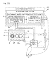
- This rolling slide fatigue life testing apparatus is made up of a testing apparatus main body 140, a testing equipment main body control apparatus 141 for controlling the testing apparatus main body 140, and a water concentration calculation section 142.
- the testing apparatus main body 140 includes a test oil bath 101 in which a lubricant oil 5A is filled in such a fashion that a rolling component part simulation product 3, which is an object to be tested, is immersed, a simulated rolling component part drive device 120 for actuating the rolling component part simulation product 3 within the test oil bath 101, a syringe pump 104 which is a water injector for injecting water into the lubricant oil within the test oil bath 101, an electrostatic capacitance meter 105 which is an electrostatic capacitance measuring instrument for measuring the electrostatic capacitance of the lubricant oil 5A within the test oil bath 101, and a thermocouple 106 which is an oil temperature measuring instrument for measuring the oil temperature of the lubricant oil 5A within the test oil bath 101.
- the rolling component part simulation product 3 is a rolling component part, in which an object to be tested made of a material for a rolling component part made of a steel material is included as a constituent element, which component is simulated for testing purpose.
- the rolling component part simulation product 3 is the one that simulates a thrust bearing assembly which is one kind of rolling component parts, and includes a plurality of rolling elements 3c in the form of balls interposed between an inner ring 3a and an outer ring 3b with the outer ring 3b constituting the object to be tested.
- the outer ring 3b of the rolling component part simulation product, which is the object to be tested is of a cylindrical shape having an end face defining a rolling surface.
- this rolling component part simulation product 3 has the rolling elements 3c of a larger size as compared with those in the thrust bearing assembly which is an actual rolling component part.
- the rolling elements 3c were made in larger size.
- the inner ring 3a is employed in the form of a specially made inner ring having a groove in which such larger rolling elements 3 can roll.
- the water concentration calculation section 142 is capable of calculating the contaminant water concentration in the previously described lubricant oil in accordance with the predetermined rule from the electrostatic capacitance, measured by the electrostatic capacitance meter 105, and the oil temperature measured by the thermocouple 106.
- the water concentration calculation section 142 has a relation setting segment 143 in which relations between the electrostatic capacitance and the oil temperature and the mixed water concentration are set by computing formulas and/or tables, and calculates the contaminant water concentration based on the electrostatic capacitance and the oil temperature both inputted with the use of a rule defined in the relation setting segment 143.
- the testing equipment main body control apparatus 141 includes a rolling component part simulation product control section 144 for controlling the rolling component part simulation product drive device 120, a pump control section 145 for controlling the syringe pump 104, and a control section (not shown) for controlling the testing apparatus main body 140 and other drive portions.
- the testing equipment main body control apparatus 141 is a computer type sequencer or a numerical control apparatus and is comprised of a computer such as, for example, a personal computer or the like and a program executed thereby.
- the water concentration calculation section 142 is comprised of a computer such as, for example, a personal computer or the like and a program executed thereby.
- the water concentration calculation section 142 may be employed in the form of either a computer forming the testing equipment main body control apparatus 141 or a computer independent from the testing equipment main body control apparatus 141.
- This rolling slide fatigue life testing method is carried out in the following manner with the use of the testing apparatus of the construction described hereinabove.
- the rolling component part simulation product 3, which is the object to be tested is immersed into the lubricant oil 5A accommodated within the test oil bath 101 and is actuated to perform a testing of a rolling slide fatigue life of the outer ring 3b, which is the object to be tested forming the rolling component part simulation product 3.
- water as a source of hydrogen is injected into the lubricant oil 5A, and the contaminant water concentration in the lubricant oil 5A is measured with the use of the water concentration calculation section 142 based on the electrostatic capacitance of the lubricant oil 5A, which is measured by the electrostatic capacitance meter 105, and the oil temperature, which is measured by the thermocouple 106.
- an oil bath lubricating mechanism is employed as a mechanism for supplying the lubricant oil 5A into the test oil bath 101 and the contaminant water concentration in the lubricant oil 5A within the test oil bath 101 is measured.
- oil bath lubricating mechanism refers to a mechanism for lubricating, while the lubricant oil is accumulated within the test oil bath 101, the rolling component part simulation product with the lubricant oil so accumulated therein.
- the measured contaminant water concentration is fed back to the syringe pump 104 to change the amount of water injected so that the contaminant water concentration can be controlled.
- the pump control section 145 referred to above causes the injection rate by the syringe pump 104 to be changed so that the contaminant water concentration may fall within a predetermined range in accordance with a predetermined rule in dependence on the contaminant water concentration outputted by the water concentration calculation section.
- an electric current is supplied by an electric conduction device 147 so as to flow between contact elements (specifically, a pair of the raceway rings 3a and 3b) of the rolling component part simulation product 3 to measure the metal contact interval.
- a main shaft 107 of a servomotor 107A in the rolling component part simulation product drive device 120 and a spindle 108 for actuating the rolling component part simulation product 3 when connected with the inner ring 3a, which will become a constituent element of the rolling component part simulation product 3, are connected directly with each other to perform a rocking motion.
- the spindle 108 may have the rolling component part simulation product as one of the constituent elements.
- the main shaft 107 of the servomotor and the spindle 108 are connected with each other by means of an insulation coupling 132. Support bearings for the spindle 108 utilize ceramic rolling element bearings 133.
- the rolling component part simulation product 3 is rendered to be a component simulating a thrust ball bearing assembly in the instance as shown in Fig. 8 and the outer ring 3b, which will form the object to be tested, is fixedly placed on a support table (not shown) or the like and the inner ring 3a is fixed to the spindle 108.
- a head portion 146 of the rolling element simulated body drive device 120 is formed.
- the head portion 146 is represented by a mechanism sections that actuate one or a set of rolling component part simulated bodies 3. In the illustrated embodiment only one head portion 146 is employed, but a plurality of head portions 146 may be employed to enable a plurality of rolling component part simulated bodies 3 to be tested simultaneously.
- the anti-hydrogen brittleness evaluation in the rolling slide fatigue life test it is not possible to control the inversion concentration of diffusible hydrogen in the steel material. Also, it is a accelerated test conducted under severe conditions and does not simulate actual operation conditions. Regarding the anti-hydrogen brittleness evaluation of the steel material, the evaluation with the inversion concentration of the diffusible hydrogen being controlled is made available. In contrast thereto, the anti-hydrogen brittleness evaluation such as, for example, the type of lubricant oil, additives to the lubricant oil, a surface treatment applied to a contact surface of the contact element and others need be evaluated through the rolling slide fatigue life test in which, as is the case with this embodiment, the inversion concentration of the diffusible hydrogen cannot be controlled.
- the rolling slide fatigue life testing method in accordance with this embodiment is effective in efficiently initiating the premature damage originating from the hydrogen brittleness so that antidote elements appropriate to conditions of use may be assessed. It is to be noted that, from the standpoint of acquiring the understanding from users, it is desirable to perform the anti-hydrogen brittleness evaluation of the steel material through the rolling slide fatigue life test.
- the rolling slide fatigue life test having the following functions (1) to (5) is desirable. It is, however, to be noted that in order to avoid influences on head portions 146 in the testing apparatus, although in Fig. 8 , the oil bath lubrication mechanism is employed for each of the head portions, a circulating oiling mechanism may be employed. Regardless of whether the oil bath lubrication mechanism is employed or whether the circulating oiling mechanism is employed, tests can be conducted with different conditions for each of the head portions provided that it is provided in each of the head portions.
- the site of injection of water is the test oil bath 101, while the test oil bath 101 or a circulating oiling portion of the circulating oiling mechanism is chosen where the circulating oiling mechanism is used in the head portion 146.
- the saturated water concentration of the lubricant oil of a mineral oil type with no additive employed is at most 200 weight ppm.
- the electrostatic capacitance meter 105 for measuring the electrostatic capacitance is broadly classified into the following two types. One of them is a type that can measure to a value equal to or lower than the saturated water concentration and the remaining type is a type that can measure to a value in excess of the saturated water concentration and even when water becomes clouded. While the former type is more generally used, the latter includes a type capable of measuring the contaminant water concentration in excess of 10% or higher.
- the saturated water concentration of the lubricant oil of the mineral oil type is at most 200 weight ppm. According to the rolling slide fatigue life test, in which the water mixed oil of 200 weight ppm in concentration is regularly replaced, it is reported that no influence of water is found. Although the saturated water concentration of the mineral oil type that is free from any additive is minute, the saturated water concentration will become markedly high with the lubricant oil of a synthesized oil type and, even with the mineral oil based lubricant oil depending on the type of an additive used.
- the electrostatic capacitance meter capable of only measuring the contaminant water concentration of a value lower than the saturated water concentration can be used to measure the saturated water concentration in the lubricant oil 5A. If the relation between the contaminant water concentration and the rolling slide fatigue life is determined, there is the possibility that the saturated water concentration peculiar to the lubricant oil may be one of indications of the anti-hydrogen brittleness.
- the actual rolling component part 3 is not used at a constant rotational speed under one direction rotation. Because of it, it is desirable that other than the constant rotational speed and one direction rotation, it can undergo an accelerated and decelerated operation and a rocking motion. As for the accelerated and decelerated operation, there is the necessity that it can be set at least to such a pattern as shown in Fig. 9 .
- six parameters including the acceleration (r max - r min )/t a , a high speed rotational number r max , the retention time t max at the high speed rotational number, the deceleration (r max - r min )/t d , a low speed rotational number r min and the retention time t min at the low speed rotational number can be arbitrarily set and, taking it as one pattern, acceleration and deceleration are repeated.
- the acceleration (r max - r min )/t a a high speed rotational number r max , the retention time t max at the high speed rotational number, the deceleration (r max - r min )/t d , a low speed rotational number r min and the retention time t min at the low speed rotational number can be arbitrarily set and, taking it as one pattern, acceleration and deceleration are repeated.
- the rocking motion unlike the case with the rotation, vibration does not change markedly even though damage occurs.
- the rocking motion is effected by directly connecting the main shaft 107 of the servomotor with the spindle 108 of the testing mechanism, which includes the rolling component part simulation product 3 as one of the constituent components, and then effecting the rocking motion, so that a superposed vibration component can be preferably eliminated.
- the rigidity of the spindle 108 and others of the testing mechanism as high as possible.
- the purpose of use of the function (5) above lies in the following two points.
- One of them is to measure the metal contact interval of the contact surface with a weak electric current supplied so as to flow between the contact elements of the rolling component part simulation product 3.
- the other of them is to frictionally wear a positive pole side with a large electric current of about 1A supplied between the contact elements.
- the rolling component part simulation product 3 has been shown and described as employed in the form of a thrust bearing type, since even in the case of the thrust bearing type the direction of rotation of steel balls and the direction of revolution of the steel balls are different from each other, a slide occurs in the contact surfaces of the test piece and the steel balls in the rolling component part simulation product 3. Also, in order to apply the slide to the contact surface positively, a motion mechanism of the contact elements may be devised.
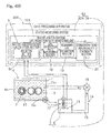
- Figs. 10 and 11 are conceptual diagrams showing respective examples of the testing device used in the practice of this rolling slide fatigue life testing method.
- a circulating oiling mechanism 109 is employed as a mechanism for supplying the lubricant oil 5A into the test oil bath 101.
- the circulating oiling mechanism 109 employed in this example shown in Fig. 10 includes a circulation pump 111 arranged on a circulating passage 110, an electrostatic capacitance meter 105 and a thermocouple 106. Even in this case, the electrostatic capacitance meter 105 and the thermocouple 106 may be provided in the test oil bath 101.
- the testing device shown in Fig. 11 the testing device shown in and described with reference to Fig.
- a reserve tank 112 is provided between a discharge port of the lubricant oil 5A in the test oil bath 101 and the circulation pump 111 so that, while the lubricant oil 5A is accumulated within the reserve tank 112, the lubricant oil 5A can be stirred by a magnetic stirrer 113 and the electrostatic capacitance and the oil temperature can then be measured.
- the thermocouple 106 is provided in the reserve tank 112. In order for the lubricant oil 5A and the water to be sufficiently mixed together, the capacity of the reserve tank 112 may be reduced to increase a stirring effect. To give an indication, the amount of the lubricant oil is preferably equal to or smaller than 100 mL.
- the discharge port of the lubricant oil 5A in each of the test oil bath 101 and the reserve tank 112 is rendered to be a bottom corner portion 101a or 112a (shown by the circle as enlarged in Fig. 11 ).
- each of the test oil bath 101 and the reserve tank 112 be rendered to be of a cylindrical shape and that a groove shaped recess 101aa or 112aa be provided on an exterior angle side as a so-called recess so as to extend the entire circumference of such bottom corner portion 101a or 112a.
- a tapered outer ring test piece 114 shown in Fig. 12A (finished by grinding after a heat treatment, the surface roughness Rq of an inner diametric raceway surface being Rq ⁇ 0.03 ⁇ m) was prepared.
- the heat treatment is carried out by heating the test piece under an atmosphere of RX gas at 850°C for 50 minutes and then quenched, followed by tempering at 180°C for 120 minutes.
- the test was conducted on a rolling component part simulation product 3 comprised of the tapered outer ring test piece 114 combined with an inner ring 115 (a standard quenched and tempered product of SUJ2) of an angular ball bearing 7306B, thirteen steel balls 116 (standard quenched and tempered products of SUJ2) and a retainer 117.
- the tapered outer ring test piece 114 was tapered in shape because, when rotated in contact with the steel balls 116 at a contact angle, the steel balls 116 would spin to slide on a surface of contact with the outer ring test piece 114. If the slide occurs, the frequency of occurrence of the premature damage originating from the hydrogen brittleness will become high.
- Fig. 13 illustrates schematically the testing device used in the practice of the testing method according to this specific example.
- a mechanism section shown on a left side thereof represents an evaluation side portion 120a and a mechanism section on a right side is a dummy side portion 120b.
- An additive free turbine oil of VG100 (having a density of 0.887 g/cm 3 and a kinetic viscosity of 100.9 mm 2 /s @ 40°C and 11.68 mm 2 /s @ 100°C) was used for the lubricant oil and 200 weight ppm, of 5 wt% purified water was mixed in such lubricant oil.
- On the evaluation side 60 mL of a water mixed oil was charged and an inlet (a lower side) and an outlet (an upper side) for the lubricant oil was connected together by means of a tube 118 to form a closed system. Since a flow of the lubricant oil occurs by a pumping action in a direction shown by the arrow in Fig.
- the water mixed oil is circulated and stirred.
- the test was continued for 20 hours and, unless any damage occurred during the testing hours, it was replaced with a newly prepared water mixed oil.
- the 20 hour test and the replacement of the water mixed oil were repeated until the damage occurred.
- the detection of the damage was carried with the use of a vibration gauge. It is to be noted that a cylindrical roller bearing 119 at the center of the testing device shown in Fig. 13 is used to apply the radial load and has no concern with the test in any way whatsoever.
- test piece 114 which is the same as that used in the previously described testing method and shown in Figs. 12A and 12B , and the testing device shown in Fig. 13 , and also using the same load condition and the rotational speed, 60 mL of the same lubricant oil (with no water mixed) was charged and the inlet (the lower side) and the outlet (the upper side) for the lubricant oil was connected together by means of the tube 118 to form the closed system. Simultaneous with the start of the test, a continuous injection of a purified water was initiated halfway from the tube 118 by means of the syringe pump 104 shown in Fig. 8 . The speed of injection of the pure water was chosen to be 0.5 mL/h.
- the contaminant water concentration in the lubricant oil can be measured based on the electrostatic capacitance and the temperature, and the electrostatic capacitance meter 105 used to measure it can be broadly classified into two types: One of them is a type merely capable of measuring a value below the saturated water concentration and the other is a type capable of measuring a value in excess of the saturated water concentration and even when water becomes clouded.
- the saturated water concentration of the lubricant oil was measured.
- the lubricant oil was an additive free turbine oil of VG100 which was used in the previously described specific example of the rolling slide fatigue life test.
- the lubricant oil was charged into a vessel 121 (resembling to, for example, the test oil bath 101 in the testing device shown in and described with reference to Fig.
- a top lid provided with a silica gel receptacle was then placed and was allowed to stand for 1 hour while having been stirred by a magnetic stirrer 113, which is capable of adjusting the temperature, and heated to 110°C, a small amount of water mixed in the oil was thereafter allowed to evaporate and be absorbed by silica gel during that time. Thereafter, as shown in a longitudinal sectional view in diagram (B) of Fig. 15 , it was maintained at 40°C and pure water was then injected at a constant rate of 0.05 mL/h with the use of the syringe pump 104.
- This electrostatic capacitance meter 105 outputs a value of 0 to 1 as a water activity. "0" indicates that the contaminant water concentration is zero and “1” indicates the contaminant water concentration is equal to or higher than the saturated water concentration.
- the saturated water concentration which is unique to the lubricant oil, may provide one of indications of the anti-hydrogen brittleness.
- the electrostatic capacitance meter 105 capable of measuring a value in excess of the saturated water concentration and even when water becomes clouded, the electrostatic capacitance was measured with variable water concentrations in the lubricant oil.
- the lubricant oil used was an additive free turbine oil of VG100 that was used in the specific example of the previously described rolling slide fatigue life test.
- 70 to 80 mL of the lubricant oil 5A was charged into a beaker 131 (resembling to, for example, the test oil bath 101 used in the testing device shown in and described with reference to Fig.
- the electrostatic capacitance was measured while the temperature was increased from about 25°C (room temperature) to about 115°C. The result thereof is shown in the chart of Fig. 19 . From this chart, it will readily be seen that a linear relation could be obtained between the contaminant water concentration and the electrostatic capacitance that have a good linear relation.
- the electrostatic capacitance depends on the contaminant water concentration and the oil temperature. If within the range in which the contaminant water concentration and the temperature may vary, a plurality of such relations as shown in Figs. 18 and 19 are determined and, with the contaminant water concentration taken as a response variable and the electrostatic capacitance as a dependent variable, a function of the oil temperature is prepared, the contaminant water concentration can be determined from the electrostatic capacitance and the oil temperature. It is, however, to be noted that in determining such an analytical curve as shown in Figs. 18 and 19 , it is desirable that not only a fresh oil, but a used oil having a different aspect of use be also measured.
- the rolling component part simulation product 3 including the object to be tested as a constituent component is immersed and operated in the lubricant oil 5A accumulated within the test oil bath 101, water is injected into the lubricant oil 5A and the electrostatic capacitance and the oil temperature in the lubricant oil 5A are measured by the electrostatic capacitance and the oil temperature, with the disturbance reduced as small as possible and while simulating the actual machine as faithfully as possible the premature damage originating from the hydrogen brittleness is efficiently caused to occur and antidote elements appropriate to conditions of use of the rolling component part simulation product 3 may be assessed.
- a status monitoring system 40 used in this rolling device includes, in addition to the contaminant water concentration detection unit 11, which includes the water concentration calculation section 9, having the function of monitoring the contaminant water concentration in the lubricant oil used in the rolling device 1, and the abnormality diagnostic section 10 for the contaminant water concentration, a vibration abnormality diagnostic section 51, a displacement abnormality diagnostic section 52, an internal cracking abnormality diagnostic section 53, an impurity abnormality diagnostic section 54, an integrated abnormality diagnostic section 55 and a communication unit 56.
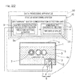
- the rolling device 1 shown in Fig. 20 corresponds to a speed-increasing gear assembly 440 and a main shaft bearing device 461 both in a wind turbine generator 400 best shown in Fig. 21 .
- the internal structure of the speed-increasing gear assembly 440 employed in the wind turbine generator 400 is similar to that in the rolling device 1 shown in Fig. 7 that is referred to in describing the first embodiment and, therefore, the details thereof are not reiterated for the sake of brevity.
- Fig. 21 illustrates a diagram schematically showing the structure of the wind turbine generator.
- the wind turbine generator 400 includes a main shaft 420, a blade 430, a speed-increasing gear assembly 540, an electric generator 550, a main shaft bearing device 461 having a main shaft bearing 460, and a data processing apparatus 2.
- the data processing apparatus 30 is comprised of a computer for performing a calculating process in the status monitoring system 40, employed in this wind turbine generator, and a program executed thereby.
- the speed-increasing gear assembly 440, the electric generator 450, the main shaft bearing 460 and the data processing apparatus 2 are all accommodated within a nacelle 490 which is in turn supported by a tower 500.
- the main shaft 420 protrudes within the nacelle 490 and is in turn coupled with an input shaft of the speed-increasing gear assembly 440 and is rotatably supported by the main shaft bearing 460.
- the main shaft 420 transmits a rotational torque, generated by the blade 430 then receiving the wind, to the input shaft of the speed-increasing gear assembly 440.
- the blade 430 is provided at a tip end of the main shaft 420 and converts the wind force into the rotational torque which is transmitted to the main shaft 420.
- the main shaft bearing 460 is fixedly installed within the nacelle 490 through a bearing housing 462 and rotatably supports the main shaft 420.
- the bearing housing 462, the main shaft bearing 460 and a lubricating mechanism (not shown) for lubricating the main shaft bearing 460 with oil cooperate with each other to form one of the rolling devices 1 shown in Fig. 20 .
- the main shaft bearing 460 is comprised of a rolling bearing and is in the form of, for example, a self-aligning roller bearing, a tapered roller bearing, a cylindrical roller bearing or a ball bearing. It is to be noted that any of those bearings may be of a single row type or a double row type.
- the speed-increasing gear assembly 440 is disposed between the main shaft 420 and the electric generator 450 and is configured to increase the rotational speed of the main shaft 420 and then output to the electric generator 450.
- the electric generator 450 is connected with an output shaft of the speed-increasing gear assembly 440 and generates an electric power upon receipt of the rotational torque from the speed-increasing gear assembly 440.
- the electric generator 450 may be comprised of, for example, an induction generator. It is to be noted that even within this electric generator 450, bearings for rotatably supporting a rotor are provided.
- the rolling device 1 shown in Fig. 20 is a generic term given to a device for producing a rotational motion, which device is one of mechanisms forming the wind turbine generator 400 and is represented by, for example, the speed-increasing gear assembly 440.
- the rolling device 1 may be a device comprised of the main shaft bearing device 461 and a lubricating mechanism (not shown) therefor.
- the contaminant water concentration detection unit 11 including the water concentration calculation section 9 and the abnormality diagnostic section 10 for the contaminant water concentration is provided in, for example, the data processing apparatus 30 which has been described with reference to Fig. 21 .
- the vibration abnormality diagnostic section 51 makes use of an output of a vibration sensor 70, which is used to monitor vibrations occurring in any of the bearings forming the rolling device 1, to thereby determine the presence of an abnormality in such bearing.
- the bearing, vibrations of which is monitored by the vibration sensor 70 is, for example, the main shaft bearing 460 and is installed in, for example, the bearing housing.
- the vibration sensor 70 may be comprised of an acceleration sensor of a type utilizing a piezoelectric element.
- the abnormality diagnostic section 51 processes a detection signal of the vibration sensor 70, compare the result of such processing with a predetermined threshold value S2 and determines the presence of the abnormality in the event that it is higher than the threshold value S2.
- the abnormality diagnostic section 51 may be so designed as to acquire the rotational speed of a shaft, supported by the bearing referred to above or this bearing, from a rotation sensor 210 and the utilizes the detected rotational speed in a signal processing for the determination of the presence or absence of the abnormality.
- the displacement abnormality diagnostic section 52 utilizes an output of a displacement sensor 240, which is a displacement gauge for detecting a relative displacement between the inner and outer rings, in the bearing referred to above and forming the rolling device 1, to thereby determine the presence or absence of an abnormality in the bearing.
- This displacement abnormality diagnostic section 52 compares the detected relative displacement or a value of this relative displacement which has been signal processed, with a predetermined threshold value S3 and then determines the presence of the abnormality in the event that it is higher than the threshold value S3.
- the internal cracking abnormality diagnostic section 53 makes use of an output of an AE sensor 250 for detecting an acoustic emission wave in the above described bearing forming the rolling device 1 and then compares this output or a value of this output, which has been signal processed, with a predetermined threshold value S4 to thereby determine the presence of the abnormality in the event that it is higher than the threshold value S4.
- the impurity abnormality diagnostic section 54 makes use of an output of a sensor 270 for detecting the amount of abrasion powder or other impurities contained in the lubricant oil used in the rolling device 1 and then compares this output or a value of this output which has been signal processed, with a predetermined threshold value S5 to thereby determine the presence of the abnormality in the event that it is higher than the threshold value S5.
- any of the vibration abnormality diagnostic section 51, the displacement abnormality diagnostic section 52, the internal cracking abnormality diagnostic section 53 and the impurity abnormality diagnostic section 54 may be so designed that, in the event that the contaminant water concentration detected by the water concentration calculation section 9 is higher than the threshold value S1, the corresponding threshold value S2 to S5, based on which the presence of the abnormality is determined in the associated abnormality diagnostic section 51 to 54, may be varied or a corresponding determining method may be altered.
- the integrated abnormality diagnostic section 55 determins in a comprehensive manner in accordance with a predetermined rule the result of diagnosis given out by any of the abnormality diagnostic sections 10, 51, 52, 53 or 54. It is to be noted that a process of changing the threshold values S2 to S5, with which the respective abnormality diagnostic sections 51 to 54 determine the presence or absence of the abnormality, or a corresponding determining method, depending on the contaminant water concentration detected by the previously described water concentration calculation section 9, may be carried out by the integrated abnormality diagnostic section 55.
- the measurement chamber 12 (shown in Figs. 22 , 23 , 25 and 26 ) is preferably provided as shown in any of Figs. 22 to 26 which will be referred to later.
- any type of bearing is utilized within the main shaft bearing device 41 and the speed-increasing gear assembly 440 and is lubricated by an oil.
- the measurement chamber 12 is disposed either inside or outside of a tube or a tank, through which this lubricant oil is supplied, or the rolling device 1 as shown in any one of Figs. 22 , 23 , 25 and 26 and the contaminant water concentration is measured therein.
- the abnormality diagnosis of the contaminant water concentration during the monitoring is such that in the event that the contaminant water concentration during the monitoring is higher than the threshold value S1, which is shown later in Figs. 27 and 28 and which represents a reference, a signal inviting a caution is outputted by the abnormality diagnostic section 10 shown in Fig. 20 .
- the electrostatic capacitance detector 7 and the oil temperature measuring instrument 8 comprised of the thermocouple are used in measuring the contaminant water concentration
- the use of the electrostatic capacitance ⁇ oil temperature unit 7A, in which they are integrated together makes it possible to reduce the number of works in the case sensors are individually installed.
- a housing (not shown) for integrating two sensors that is, the electrostatic capacitance meter 7 and the oil temperature measuring instrument 8 comprised of the thermocouple) plays a role of a covering for retaining each of those sensors and, in view of the fact that an effect of reducing breakages can be expected, it is considered that the reliability of the sensor itself can be increased.
- this device is used on the land or in a region where the change in climatic temperature is small, it may be suspected that as shown in Fig. 28 , even through the water concentration changes day by day, the threshold value S1 will barely be exceeded. With respect to the timing at which exfoliation resulting from the hydrogen brittleness, it is predicated by the operating hours or the accumulation of the amount of rotation, during which the threshold value S1 is exceeded.
- a high contaminant water concentration in order to perform the monitoring on a safe side, it is preferred to measure a high contaminant water concentration by providing a measurement chamber at a position lower than the tank or the oil bath and facilitating capture of water and additives to a position proximate to the sensor by the utilization of the difference in specific gravity.
- the AE sensor 250 is used concurrently in place of, or used simultaneously with, the vibration acceleration sensor, not only the exfoliation in the surface, but cracking resulting from the hydrogen brittleness, which occurs inside the metal, can be measured.
- the determination of the occurrence of the cracking by means of the AE sensor 250 may be difficult because of causeless AE waves found here and there, but where the AE waves are generated while the contaminant water concentration is high, it may be expected that the internal cracking is taking place with a high probability, and, therefore, it becomes possible to estimate the abnormality at an earlier stage.
- an impurity sensor 270 such as, for example, a deterioration sensor or the like of the oil makes it possible to predicate the occurrence of a lubrication defect that leads to breakdown of the bearing assembly. Simultaneously by considering the contaminant water concentration and applying a correction to the impurity sensor 270 such as, for example, an oil deterioration sensor or the like, predication of the premature damage of the bearing assembly resulting from the lubricant oil can become further accurate.
- the probability of occurrence, or the timing of occurrence, of the exfoliation in the bearing assembly as a result of the hydrogen brittleness can be estimated. Thanks to it, in the wind turbine generator, it becomes possible to reduce the length of time of halt in operation subsequent to the occurrence of the abnormality.
- Figs. 22 to 26 illustrate modified forms of the contaminant water concentration monitoring device 6.
- the contaminant water concentration monitoring device 6 shown in any one of Figs. 22 to 26 may be employed. It is to be noted that in those Figs. 22 to 26 , other structural features than those of the status monitoring system of the wind turbine generator are not shown.
- a ninth embodiment shown in Fig. 23 the structure of the rolling device 1 except for the data processing apparatus 30 is rendered to be similar to the previously described third embodiment shown in Fig. 3 . Since other functions and effects are also similar to those afforded by the third embodiment, the details thereof are not reiterated for the sake of brevity. It is to be noted that other structural features and effects afforded by the ninth embodiment shown in Fig. 23 are similar to those afforded by the seventh embodiment shown in and described with reference to Fig. 20 .
- a tenth embodiment shown in Fig. 24 the structure of the rolling device 1 except for the data processing apparatus 30 is rendered to be similar to the previously described fourth embodiment shown in Fig. 4 .
- Other functions and effects are also similar to those afforded by the fourth embodiment and, therefore, the details thereof are not reiterated for the sake of brevity. It is to be noted that other structural features and effects are similar to those afforded by the seventh embodiment shown in and described with reference to Fig. 20 .
- the structure of the rolling device 1 except for the data processing apparatus 30 is rendered to be similar to the previously described fifth embodiment shown in Fig. 5 .
- Other functions and effects are also similar to those afforded by the fifth embodiment and, therefore, the details thereof are not reiterated for the sake of brevity.
- Other structural features and effects are similar to those afforded by the tenth embodiment shown in to Fig. 24 .
- a twelfth embodiment shown in Fig. 26 the structure of the rolling device 1 except for the data processing apparatus 30 is rendered to be similar to the previously described sixth embodiment shown in Fig. 6 .
- Other functions and effects are also similar to those afforded by the sixth embodiment and, therefore, the details thereof are not reiterated for the sake of brevity.
- this embodiment unless otherwise specifically referred to, it is similar to the previously described seventh embodiment shown in Fig. 20 .
- the vibration sensor 70 is installed in a bearing forming the rolling device 1 shown in Fig. 20 , for example, the main shaft bearing 460.
- This vibration sensor 70 detects a vibration of the bearing assembly and outputs its detection value to the vibration abnormality diagnostic section 51 in the data processing apparatus 2.
- the vibration sensor 70 includes an acceleration sensor or the like of a type utilizing a piezoelectric element as hereinbefore described.
- the vibration abnormality diagnostic section 51 includes high pass filters (HPF) 510, 550, effective value calculation blocks 520, 560, an envelope processing block 540, a storage block 580 and a diagnostic block 590.
- the effective value calculation block 520 is a first calculation block referred to in the claims and the effective value calculation block 560 is a second calculation block referred to in the claims.
- the HPF 510 receives from the vibration sensor 70 the detection value indicative of the vibration occurring in the bearing assembly. And, this HPF 510 allows a signal component, which is higher than a predetermined frequency, to pass therethrough and cuts off a low frequency component. This HPF 510 is provided for removing a direct current component contained in a vibration waveform of the bearing. It is to be noted that if the vibration sensor 70 is of a type containing no direct current component in its output, the use of the HPF 510 may be dispensed with.
- the effective value calculation block 520 receives from the HPF 510 the vibration waveform of the bearing from which the direct current component has been removed. And, the effective value calculation block 520 calculates an effective value (which is also referred to as a root means square (RMS) value) of the vibration waveform of the bearing and then outputs the calculated effective value of the vibration waveform to the storage block 580.
- RMS root means square
- the envelope processing block 540 receives the detection value descriptive of the vibration occurring in the bearing. And, the envelope processing block 540 performs an enveloping process on the detection signal received thereby to generate an envelope waveform of the vibration waveform of the bearing. It is to be noted that the enveloping process calculated in the envelope processing block 540 may be of any known technique and, as one example thereof, the vibration waveform of the bearing measured by the use of the vibration sensor 70 is rectified to an absolute value and is then passed through a low pass filter (LPF) to generate the envelope waveform of the vibration waveform of the bearing 6.
- LPF low pass filter
- the high pass filter 550 receives from the envelope processing block 540 the envelope waveform of the vibration waveform of the bearing. And, the high pass filter 550 allows, with respect to the envelope waveform received thereby, a signal component that is higher than a predetermined frequency and cuts off a low frequency component.
- the high pass filter 550 is provided for removing a direct current component contained in the envelope waveform and extracting an alternating current component of the envelope waveform.
- the effective value calculation block 560 receives from the high pass filter 560 the envelope waveform from which the direct current component has been removed, that is the alternating current component of the envelope waveform. And, the effective value calculation block 560 calculates an effective value (RMS value) of the alternating current component of the envelope waveform received thereby and outputs the calculated effective value of the alternating current component of the envelope waveform to the storage block 580.
- RMS value effective value
- the storage block 580 stores the effective value of the vibration waveform of the bearing, which has been calculated by the effective value calculation block 520, and the effective value of the alternating current component of the envelope waveform, which has been calculated by the effective value calculation block 560, in synchronized fashion and from moment to moment.
- This storage block 580 is comprised of, for example, a readable and writable, nonvolatile memory or the like.
- the diagnostic block 590 reads the effective value of the vibration waveform of the bearing and the effective value of the alternating current component of the envelope waveform, both stored in the storage block 580 from moment to moment, from the storage block 580 and diagnoses the abnormality of the bearing on the basis of two effective values readout therefrom.
- the threshold value S2 referred to previously is used in this abnormality diagnosis. More specifically, the diagnostic block 590 diagnoses the presence or absence of the abnormality in the bearing assembly on the basis of a chronological changeion of both of the effective value of the waveform of the bearing and the effective value of the alternating current component of the envelope waveform.
- the effective value of the vibration waveform of the bearing calculated by the effective value calculation block 520 is an actual value of a raw waveform which has not yet subjected to the enveloping process
- the increase of the value is small in the case of an impulse-like vibration in which a signal increased only when the rolling elements move past the site of exfoliation that has occurred in, for example, a portion of the raceway ring, but the increase of the value is considerable in the case of the persistent vibration that is generated in the event of the occurrence of a surface roughening resulting from a contact between the raceway ring and the rolling element or an insufficient lubrication or the like.
- the effective value of the alternating current component of the envelope waveform calculated by the effective value calculation block 560 is such that the increase of the value is small or no increase occurs in the case of the persistent vibration generated in the event of the surface roughening of the raceway ring and the insufficient lubrication, the increase of the value becomes large in the case of the impulse-like vibration.
- this Specific Example 1 by the utilization of the effective value of the vibration waveform of the bearing and the effective value of the alternating current component of the envelope waveform, detection of the abnormality, which cannot be detected with one of those effective values, is enabled and a further accurate abnormality diagnosis is made realizable.
- Figs. 30 to 33 illustrate respective waveform charts showing the vibrations of the bearing measured with the use of the vibration sensor 70. It is to be noted in Figs. 30 to 33 , the vibration waveforms exhibited in the case that the rotational speed of the main shaft 420 (best shown in Fig. 21 ) is held at a constant value.
- Fig. 30 illustrates a waveform chart showing the vibration waveform of the bearing exhibited when no abnormality occurs in the bearing.
- the axis of abscissas represents time and the axis of ordinates represents the degree of vibration, which represents the magnitude of the vibration.
- Fig. 31 is a waveform chart showing the vibration waveform of the bearing observed when the surface roughing of the raceway ring of the bearing and/or the insufficient lubrication occur.
- the degree of vibration increases and a condition in which the degree of vibration increases occurs persistently. No prominent peak appears in the vibration waveform. Accordingly, when with respect to such vibration waveform, the effective value (output of the effective value calculation block 520 shown in Fig. 29 ) of the vibration waveform, when no abnormality occur in the bearing, and the effective value (output of the effective value calculation block 560 shown in Fig.
- Fig. 32 illustrates a waveform chart showing the vibration waveform of the bearing at the initial stage at which the exfoliation occurs in the raceway ring of the bearing.
- the initial stage of the exfoliation abnormality is represented by a condition in which the exfoliation occurs in a portion of the raceway ring and, since a considerable vibration is generated as the rolling element moves past the site of exfoliation, pulse-like vibrations occur cyclically according to the rotation of a shaft.
- the increase of the degree of vibration is small.
- the effective value of the vibration waveform when no abnormality occur in the bearing, and the effective value of the alternating current component of the envelope waveform are compared, the effective value of the alternating current component of the envelope waveform increases and the effective value of the raw vibration waveform does not increase so much.
- Fig. 33 illustrates a waveform chart showing the vibration waveform of the bearing observed at the terminal stage of the exfoliation abnormality.
- the terminal stage of the exfoliation abnormality is represented by a condition in which the exfoliation is transited over the entire area of the raceway ring and, as compared with the initial stage of abnormality, the degree of vibration increases wholly and the tendency of the pulse-like vibration is weakened. Accordingly, when with respect to such vibration waveform the effective value of the vibration waveform at the initial stage of the exfoliation abnormality and the effective value of the alternating current component of the envelope waveform are compared, the effective value of the raw vibration waveform increase and the effective value of the alternating current component of the envelope waveform is lowered.
- Fig. 34 illustrates a chart showing respective chronological changes of the effective value of the vibration waveform of the bearing and the effective value of the alternating current component of the envelope waveform, when the exfoliation occurred in a portion of the raceway ring of the bearing and subsequently transited over the entire area of the raceway ring,. It is to be noted that in Fig. 34 and also in Fig. 35 reference to which will be made later, the chronological change of each of those effective values exhibited when the rotational speed of the main shaft 420 is at a constant value.
- a curve k1 represents the chronological change of the effective value of the vibration waveform exhibited when no envelope process is applied while a curve k2 represents the chronological change of the effective value of the alternating current component of the envelope waveform.
- both of the effective value (k1) of the vibration waveform and the effective value (k2) of the alternating current component of the envelope waveform are small.
- the vibration waveform at the timing t1 represents such a waveform as shown in Fig. 32 , reference to which has already been made above.
- the effective value (k2) of the alternating current component of the envelope waveform increases considerably and, on the other hand, the effective value (k1) of the vibration waveform with no envelope process being applied does not increase so much (in the vicinity of the timing t2).
- the effective value (k1) of the vibration waveform with no envelope process being applied increases considerably and, on the other hand, the effective value (k2) of the alternating current component of the envelope waveform is lowered (in the vicinity of the timing t3) as discussed with reference to Fig. 33 .
- Fig. 35 illustrates a chart showing the chronological change of the effective value of the vibration waveform of the bearing and the effective value of the alternating current component of the envelope waveform when the surface roughening of the insufficient lubrication occurs in the raceway ring of the bearing.
- a curve k1 represents the chronological change of the effective value of the vibration waveform exhibited when no envelope process is applied while a curve k2 represents the chronological change of the effective value of the alternating current component of the envelope waveform.
- both of the effective value (k1) of the vibration waveform and the effective value (k2) of the alternating current component of the envelope waveform are small. It is to be noted that the vibration waveform at the timing t11 becomes that similar to the waveform shown in Fig. 30 .
- the effective value (k1) of the waveform, to which no envelope process is applied increases and, on the other hand, the increase of the effective value (k2) of the alternating current component of the envelope waveform is not observed (in the vicinity of the timing t12).
- the abnormality diagnosis of the bearing assembly can be further accurately performed.
- the occurrence of an abnormality in the bearing is diagnosed on the basis of the effective value of the vibration waveform of the bearing, which has been measured by the use of the vibration sensor 70, and the effective value of the alternating current component of the envelope waveform, which is generated by applying the envelope process to the vibration waveform measured by the use of the vibration sensor 70, the accurate abnormality diagnosis as compared with the conventional technique relying on the frequency analysis can be realized. Also, the unnecessary maintenance can be reduced and the cost incurred in the maintenance can be reduced.
- the magnitude of vibration of the bearing such as, for example, the main shaft bearing 460 changes.
- the degree of vibration of the bearing increase with an increase of the rotational speed of the main shaft. Accordingly, in the Specific Example 2, the effective value of the vibration waveform of the bearing and the effective value of the alternating current component of the envelope waveform are normalized with the rotational speed and the abnormality diagnosis of the bearing assembly is performed with the use of the effective values so normalized.
- Fig. 36 illustrates a functional block diagram showing functionally the structure of the vibration abnormality diagnostic section 51 employed in this Specific Example 2.
- the abnormality diagnostic section 51 is similar to the abnormality diagnostic section 51 employed in the previously described Specific Example 1 shown in Fig. 29 , except that a modified vibration degree calculation block 530, a modified modulation degree calculation block 570 and a speed function generation block 600 are additionally employed.
- the speed function generation block 600 receives a detection value descriptive of the rotational speed of the main shaft 420 from the rotation sensor 210. It is to be noted that the rotation sensor 210 may be capable of outputting a detection value descriptive of the rotational position of the main shaft 420 so that the rotational speed of the main shaft 420 can be calculated in the speed function generation block 600.
- the speed function generation block 600 generates a speed function A(N) for normalizing the effective value of the vibration waveform of the bearing, calculated by an effective value calculation block 520, with the rotational speed N of the main shaft 420 and a speed function B(N) for normalizing the effective value of the alternating current component of the envelope waveform, calculated by an effective value calculation block 560, with the rotational speed N of the main shaft 420.
- the modified vibration degree calculation block 530 receives the effective value of the vibration waveform of the bearing from an effective value calculation block 520 and the speed function A(N) from the speed function generation block 600. Then, the modified vibration degree calculation block 530 makes use of the speed function A(N) to calculate a value, which corresponds to the effective value of the vibration waveform, calculated by the effective value calculation block 520, that is normalized with the rotational speed of the main shaft 420 (hereinafter referred to as "modified vibration degree").
- the modified vibration degree calculation block 530 outputs to the storage block 580 a modified vibration degree Vr* calculated by the formula (3) above.
- the modified modulation degree calculation block 570 receives the effective value of the alternating current component of the envelope waveform from the effective value calculation block 560 and the speed function B(N) from the speed function generation block 600.
- the modified modulation degree calculation block 570 makes use of the speed function B(N) to calculate a value which corresponds to the effective value of the alternating current component of the envelope waveform, calculated by the effective value calculation block 560, that is normalized with the rotational speed of the main shaft 420 (hereinafter referred to as "modified modulation degree").
- Vea represents the average value of Ve during the time span 0 to T.
- the modified modulation degree calculation block 570 outputs to the storage block 580 the modified modulation degree Ve* calculated by the formula (4) above.
- the modified vibration degree calculation block 530 outputs to the storage block 580 the modified vibration degree Vr* calculated by the formula (3) referred to previously.
- the modified vibration degree Vr* and the modified modulation degree Ve* which have been stored in the storage block 580 from moment to moment, are read out by a diagnostic block 590 and, on the basis of the chronological change of the modified vibration degree Vr* and the modified modulation degree Ve*, which have been so read out, the abnormality diagnosis of the bearing is performed by the diagnostic block 590.
- the rotation sensor 210 may be fitted to the main shaft 420 and a rotation sensor equipped bearing assembly of a type, in which the rotation sensor 210 is incorporated in the bearing assembly, may be used in the bearing that is an object to be diagnosed.
- the further accurate abnormality diagnosis can be realized with disturbances resulting from the change in rotational speed having been removed.
- Fig. 37 illustrates a functional block diagram functionally showing the structure of the vibration abnormality diagnostic section 51 employed in the practice of the Specific Example 3.
- the abnormality diagnostic section 51 is similar to the abnormality diagnostic section 51, shown in and described with reference to Fig. 36 , except that frequency analysis blocks 620 and 630 are additionally employed.
- the frequency analysis block 620 received from the HPF 510 a vibration waveform of the bearing from which a direct current component has been removed.
- the frequency analysis block 620 performs a frequency analysis on the vibration waveform of the bearing so received and then outputs a result of the frequency analysis to the storage block 580.
- the frequency analysis block 620 applies the fast Fourier transform (FFT) process on the vibration waveform of the bearing which it receives from the high pass filter 510, and a peak frequency exceeding a predetermined threshold value is subsequently outputted to the storage block 580.
- FFT fast Fourier transform
- the frequency analysis block 630 receives from the high frequency filter 550 an alternating current component of the envelope waveform from which a direct current component has been removed. And, the frequency analysis block 630 performs a frequency analysis on the alternating current component of the envelope waveform so received and then outputs a result of the frequency analysis to the storage block 580.
- the frequency analysis block 630 applies a FFT process on the alternating current component of the envelope waveform, which is received from the high pass filter 550, and a peak frequency exceeding a predetermined threshold value is subsequently outputted to the storage block 580.
- the diagnostic block 590 referred to above reads out from the storage block 580 the results of the frequency analysis performed respectively by the frequency analysis blocks 620 and 630 together with the modified vibration degree Vr* and the modified modulation degree Ve* and performs a further reliable abnormality diagnosis by concurrently utilizing the results of the frequency analysis together with the chronological changes of the modified vibration degree Vr* and the modified modulation degree Ve*.
- the results of the frequency analysis performed respectively by the frequency analysis blocks 620 and 630 can be used in estimating the site of generation of the abnormality when the abnormality is detected by the abnormality diagnosis based on the modified vibration degree Vr* and the modified modulation degree Ve*.
- a peak of a vibration of a particular frequency theoretically determined from the geometric structure within the bearing assembly and the rotational speed is generated in dependence on the damaged site (inner ring, outer ring, rolling elements).
- frequency analysis blocks 620 and 630 have been shown and described as added to the Specific Example 2 described hereinbefore, the frequency analysis blocks 620 and 630 may be added to the abnormality diagnostic section 51 employed in the practice of the Specific Example 1 shown in and described with reference to Fig. 29 .
- the reliability of the abnormality diagnosis can be further increased and the abnormality occurring site can be further accurately diagnosed.
- Fig. 38 illustrates a functional block diagram showing functionally the structure of the vibration abnormality diagnostic section 51 employed in the practice of the Specific Example 4.
- the abnormality diagnostic section 51 is similar to the abnormality diagnostic section 51 shown in and described with reference to Fig. 37 , but differs therefrom in that it includes a diagnostic block 590A in place of the diagnostic block 590.
- a displacement sensor 240 In addition to the vibration sensor 70 and the rotation sensor 210, at least one of a displacement sensor 240, an AE (Acoustic Emission) sensor 250, a temperature sensor 260 and a magnetic type iron powder sensor which is an impurity sensor 270 (hereinafter referred to as "magnetic type iron powder sensor 270") is further employed.
- the diagnostic block 590A receives a detection value from at least one of the displacement sensor 240, the AE sensor 250, the temperature sensor 260 and the magnetic type iron powder sensor 270 that are provided therein. Also, the diagnostic block 590A reads out from the storage block 580 the modified vibration degree Vr* and the modified modulation degree Ve* and respective results of the frequency analysis performed by the frequency analysis blocks 620 and 630.
- the diagnostic block 590A makes concurrent use of the detection value, received from at least one of the displacement sensor 240, the AE sensor 250, the temperature sensor 260 and the magnetic type iron powder sensor 270, together with the modified vibration degree Vr*, the modified modulation degree Ve* and the respective results of the frequency analysis performed by the frequency analysis blocks 620 and 630 to thereby perform the abnormality diagnosis of the bearing assembly.
- the displacement sensor 240 is fitted to the bearing for detecting the relative displacement of the inner ring relative to the outer ring of the bearing 60, which relative displacement is subsequently outputted to the diagnostic block 590A.
- the diagnostic block 590A determines the occurrence of the abnormality in the bearing in the event that the detection value from the displacement sensor 240 is higher than a predetermined value (threshold value S3). It is to be noted that since the displacement sensor 240 detects the relative displacement between the outer ring and the inner ring, it is necessary to maintain the accuracy of a non-measuring surface at a high quality.
- the AE sensor 250 is fitted to the bearing for detecting an acoustic emission wave (AE signal) generated from the bearing and then outputs it to the diagnostic block 590A.
- This AE sensor 250 is excellent in detecting the internal cracking occurring in a member forming the bearing and the concurrent use of this AE sensor 250 makes it possible to early detect the exfoliation abnormality which is generated because of the internal cracking of a kind difficult to detect by the vibration sensor 70.
- the diagnostic block 590A determines the occurrence of the abnormality in the bearing.
- the temperature sensor 260 is fitted to the bearing for detecting the temperature of the bearing and then outputs a signal indicative of the temperature so detected to the diagnostic block 590A.
- the bearing evolves heat in the event of an insufficient lubrication and the undersize of a gap inside of the bearing and will fail to rotate when a seized condition occurs through a change in color of the rolling surface and/or a plastic welding. Accordingly, by detecting the temperature of the bearing with the temperature sensor 260, the abnormality such as, for example, the insufficient lubrication can be detected early.
- the previously described oil temperature measuring instrument 8 for detecting the oil temperature may be utilized.
- the diagnostic block 590A performs the abnormality diagnosis such as, for example, the insufficient lubrication by further referring to the detection value of the temperature sensor 260 when the modified vibration degree Vr* and the modified modulation degree Ve* exhibit such a behavior as shown in Fig. 37 . It is to be noted that the diagnostic block 590A referred to above may determines the occurrence of the abnormality in the bearing only by reason that the detection value from the temperature sensor 260is higher than the predetermined value.
- the temperature sensor 260 is constituted by, for example, a thermister, a platinum resistance element or a thermocouple.
- the magnetic type iron powder sensor 270 detects the amount of an iron powder contained in the lubricant for the bearing and then outputs its detected value to the diagnostic block 590A.
- This magnetic type iron powder sensor 270 is comprised of, for example, a rod shaped electrode and an electrode having a magnet built therein and is disposed in the circulating path of the lubricant for the bearing.
- the magnetic type iron powder sensor 270 captures the iron powder, contained in the lubricant, by means of the magnet and outputs a signal in the event that the electric resistance between the electrodes lowers below a predetermined value as a result of adhesion of the iron powder.
- the diagnostic block 590A when receiving the signal from the magnetic type iron powder sensor 270 determines the occurrence of the abnormality in the bearing 60.
- an optical sensor capable of detecting a turbidity of the lubricant based on a transmittance may be employed in place of the magnetic iron powder sensor 270.
- the optical sensor detects the amount of the bearing abrasion powder in the lubricant oil by projecting rays of light from a light emitting element onto the lubricant oil and detecting a change in intensity of light arriving at a light receiving element.
- the transmittance of the light is defined by the ratio between an output value of the light receiving element, when no foreign matter is admixed in the lubricant oil, and an output value of the light receiving element, when iron oxide is admixed therein, and the diagnostic block 590A determines the occurrence of the abnormality in the bearing when the transmittance thereof is higher than a predetermined value.
- the reliability of the abnormality diagnosis can be further increased.
- the concurrent use of the displacement sensor 240 the abrasion taking place within the bearing can be diagnosed and, by the concurrent use of the AE sensor 250, the exfoliation abnormality occurring as a result of the internal cracking can be diagnosed early.
- the concurrent use of the temperature sensor 260 the abnormality such as, for example, the insufficient lubrication can be diagnosed early and, by the concurrent use of the magnetic type iron powder sensor 270 and the optical sensor or the like capable of detecting the turbidity of the lubricant through the transmittance of light, the abrasion of the bearing can be diagnosed.
- the displacement abnormality diagnostic section 52, the internal cracking abnormality diagnostic section 53 and the impurity abnormality diagnostic section 54, all shown in Fig. 20 are provided as respective instruments for performing the various functions of the abnormality diagnosis for the displacement, internal cracking and impurity of the diagnostic section 590A shown in Fig. 38 , separately from the vibration abnormality diagnostic section 51.
- Fig. 39 illustrates an expanded example of the status monitoring system for the rolling device of a kind employed in this wind turbine generator.
- the nacelle 490 best shown in Fig. 21 is installed at a high location and, therefore, considering the capability of conducting the maintenance, the status monitoring system for the wind turbine generator is desirably installed at a location distant from the nacelle 490.
- the vibration waveform itself which is measured with the use of the vibration sensor 70
- to a remote place require a transmitting device having a high transmitting speed and this may result in an increase of the cost.
- the nacelle 490 is installed at the high location as discussed above, the use of a wireless communication is desirable for a communication device from the nacelle 490 to the outside.
- the calculation of the water concentration, the calculation of the modified vibration degree Vr* and the modified modulation degree Ve* and the frequency analyzing process are executed in the data processing apparatus provided in the nacelle 490, and the calculated water concentration, the calculated modified vibration degree Vr* and modified modulation degree Ve* and the calculated result of the frequency analysis (the peak frequency) are transmitted wirelessly from the nacelle 490 to the outside.
- the data transmitted warlessly from the nacelle 490 are received by a communication server connected with the Internet and the abnormality diagnosis of the bearing is performed after the data have been transmitted to a diagnostic server through the Internet.
- Fig. 39 illustrates a schematic diagram schematically showing the entire structure of the status monitoring system for the rolling device used in the wind turbine generator utilizing the communication device to the remote place.
- the status monitoring system for the wind turbine generator includes a wind turbine generator 400, a communication server 310, an Internet 320 and a bearing status diagnostic server 330.
- the structure of the wind turbine generator 400 is such as hereinbefore described and, therefore, it will not be reiterated for the sake of brevity. It is however to be noted that as will be described later, in the data processing apparatus of the wind turbine generator 400 in this example, a wireless communication block is provided in place of a diagnostic block. And, the wind turbine generator 400 makes use of the detection value of the vibration sensor 70, as best shown in Fig. 20 , to calculate the previously described modified vibration degree Vr* and modified amplitude degree Ve* and the result of the frequency analysis (where the frequency analysis is concurrently used) and outputs the results of those calculations wirelessly to the communication server 310.
- the communication server 310 is connected with the Internet 320. And, the communication server 310 receives the communicated data wirelessly from the wind turbine generator 400 and outputs the received data to the bearing status diagnostic server 330 through the Internet 320.
- the bearing status diagnostic server 330 is connected with the Internet 320. And, the bearing status diagnostic server 330 receives data from the communication server 310 through the Internet 320 and performs the abnormality diagnosis occurring in the bearing, which is provided in the wind turbine generator 400, on the basis of the modified vibration degree Vr* and modified modulation degree Ve* and the result of the frequency analysis (where the frequency analysis is concurrently used) all calculated in the wind turbine generator 400.
- Fig. 40 illustrates a functional block diagram showing functionally the structure of the vibration abnormality diagnostic section 51 in the data processing apparatus included in the wind turbine generator 400 shown in and described with reference to Fig. 39 .
- the abnormality diagnostic section 51 is similar to the abnormality diagnostic section 51 shown in and described with reference to Fig. 37 , but differs therefrom in that in place of the diagnostic block 590 a wireless communication block 280 is included.
- the wireless communication block 280 reads out from the storage block 580 the modified vibration degree Vr*, the modified modulation degree Ve* and the frequency analyzing results by the frequency analysis blocks 620 and 630 and transmits the read-out data wirelessly to the communication server 310 best shown in Fig. 39 .
- the nacelle 490 and the communication server 310 may be connected wired.
- a wiring is required, but the wireless communication device is no longer employed and the wired system generally makes it possible to transmit more information and, therefore, processing can be integrated on a main substrate in the nacelle 490.
- the status monitoring device used in the above described wind power generating device is preferably constructed independent from the existing power generation monitoring system. By so constructing, the cost of introducing the status monitoring device for the wind power generating device can be suppressed with no need to altering any existing system.
- the abnormality diagnosis of the bearing assembly provided in the wind turbine generator 400 can be performed in the bearing status diagnosis server 330 installed at the remote place, the maintenance load and the cost can be reduced advantageously.
- the provision of the wireless communication block 280 and the communication server 310 enables a signal output from the nacelle 490 to be transmitted wirelessly and, therefore, a wiring work in the nacelle 490 can be suppressed to a minimal and the no wiring work is needed inside the tower 500 used to support the nacelle 490.
- the water concentration calculation section 9 best shown in Fig. 20 may be provided in the data processing apparatus installed in the nacelle 490 or in the bearing status diagnostic server 330 best shown in and described with reference to Fig. 39 .
- the present invention can be equally applied to the status monitoring of the rolling device that form any various machines such as, for example, the rolling device forming an industrial machine, machine tool or construction machine.
- This status monitoring system 6 for the rolling device includes a status monitoring system 40A, provided in the data processing apparatus 30A, and various sensors (7, 8, 70, 210, 240, 250, 270).
- the data processing apparatus 30A is similar to that employed in the practice of the previously described first embodiment and is comprised of a computer such as, for example, a microcomputer or a personal computer, and a program executed thereby, or dedicated electronic circuits.
- the rolling device 1 shown therein may be that employed in, for example, a speed reducing mechanism or a machine tool, or in any other machine and equipment.
- the status monitoring system 40A includes a water concentration ⁇ life reduction rate monitoring section 10 which includes, other than the contaminant water concentration calculation section 9 for monitoring the contaminant water concentration in the lubricant oil used to lubricate the rolling component part 3 of the rolling device 1, a life reduction rate monitoring section 18, a remaining life estimation section 19 and a diagnostic unit 20 for a concentration abnormality, and, in addition thereto, various abnormality diagnostic sections 51 to 55 are provided.
- a water concentration ⁇ life reduction rate monitoring section 10 which includes, other than the contaminant water concentration calculation section 9 for monitoring the contaminant water concentration in the lubricant oil used to lubricate the rolling component part 3 of the rolling device 1, a life reduction rate monitoring section 18, a remaining life estimation section 19 and a diagnostic unit 20 for a concentration abnormality, and, in addition thereto, various abnormality diagnostic sections 51 to 55 are provided.
- the life reduction rate monitoring section 18 determines the life reduction rate ⁇ of the rolling component part 3 from the contaminant water concentration c, detected by the water concentration calculation section 9, with the use of a predetermined relation between the contaminant water concentration c and the life reduction rate ⁇ of the rolling element.
- the rolling component part 3 which is the object to be monitored is a bearing
- the contaminant water concentration in the bearing assembly which is the object to be monitored and which is applied to an actual machine
- the life reduction rate ⁇ is estimated from the chart of Fig. 42 .
- the experiment to determine the life reduction rate ⁇ utilizes a method of determining the threshold value S1 as will be discussed later.
- the function ⁇ (c) so determined in the manner described above is set in the life reduction rate monitoring section 18 as the relation between the contaminant water concentration c and the life reduction rate ⁇ of the rolling component part that are determined in the manner described above.
- the remaining life estimation section 19 estimates the remaining life of the rolling component part 3, which is the object to be monitored, by the utilization of the life reduction rate ⁇ outputted by the life reduction rate monitoring section 18, and a predetermined remaining life estimation formula. Where the rolling component part 3 is the bearing, the remaining life can be predicated in the following manner.
- the remaining life is estimated by utilizing the idea of Miner's rule (the idea such as disclosed in the non-patent document 11 listed previously that in the case of a material on which various reversed stress amplitudes act, where the repetition rate from the S-N diagram in "a certain breakage probability" to breakage has been made available for each stress threshold values, exfoliation or cracking occurs and the life is reached when summation of the repeat counts at the respective stresses reaches at the "certain breakage probability".) from the contaminant water concentration c and the amount of rotation (life) of the bearing assembly.
- Miner's rule the idea such as disclosed in the non-patent document 11 listed previously that in the case of a material on which various reversed stress amplitudes act, where the repetition rate from the S-N diagram in "a certain breakage probability" to breakage has been made available for each stress threshold values, exfoliation or cracking occurs and the life is reached when summation of the repeat counts at the respective stresses reaches at the "certain breakage probability".
- the relation between the contaminant water concentration c and the life (amount of rotation) in the actual bearing is derived as shown in Fig. 43 .
- the bearing life when the contaminant water concentration is zero (0) is expressed by L10 and the life of the actual bearing assembly at an arbitrarily chosen contaminant water concentration can be determined if (1 - ⁇ (c)) is multiplied by L10 of the actual bearing assembly. It is here assumed that the contaminant water concentration of the actual machine is c1. If the amount of operation Nc1 of the bearing in this condition exceeds (1 - ⁇ (c1)) ⁇ L10, the bearing is expected to break down. In other words, if Nc1/(1 - ⁇ (c1)) ⁇ L10 exceeds 1, it can be regarded that the life has reached.
- L 1 - ⁇ i N ci 1 - ⁇ c i ⁇ L 10 ⁇ 1 - ⁇ c ave ⁇ L 10
- C ave represents the expected contaminant water concentration in future's operation
- Nci represents the accumulated amount of rotation at the contaminant water concentration rank ci (where i represents the rank number)
- c 0 to c R represents ranks of the contaminant water concentration (where R represents the number of the ranks).
- C ave may be the average contaminant water concentration suffices to be the average contaminant water concentration exhibited during a time zone near to the timing at which the remaining life is calculated. For example, it may be the average value calculated for the past ten days.
- the calculation of the C ave makes use of the contaminant water concentration c detected by the water concentration calculation section 9. It is to be noted that in order to monitor on a safe side, during the measurement of the contaminant water concentration, it is recommended to measure the high contaminant water concentration by providing the measurement chamber at a lower position than the tank or the oil bath to facilitate capture of water and/or additives.
- the remaining life estimation section 19 has the above formula set therein as a predetermined remaining life estimation formula and makes use of the life reduction rate ⁇ determined by the life reduction rate monitoring section 18.
- L 10 is the L 10 of a condition with no hydrogen admixed and can be determined by means of a breakdown test. That determined value is used. It is to be noted that by conducting the breakdown test under a constant contaminant water concentration, reduction in life because of the hydrogen brittleness may be suspected. By conducting the breakdown test under this constant contaminant water concentration at various concentrations, the life relative to the contaminant water concentration such as shown in the chart of Fig. 14 comes to be readily available. Accordingly, the function of that life reduction rate is set to be ⁇ .
- the diagnostic unit 20 for the concentration abnormality compares the water concentration, detected by the water concentration calculation section 9, with the predetermined threshold value S1 and then determines the occurrence of the abnormality in the event that the result of comparison indicates the excess over the predetermined threshold value S 1.
- monitoring unit 10A detects the contaminant water concentration from the electrostatic capacitance and the oil temperature that are detected thereby in a manner similar to that employed in the practice of the previously described first embodiment of the present invention, and makes it possible to accurately determine by monitoring the contaminant water concentration in the lubricant oil 5.
- the life reduction rate ⁇ resulting from the hydrogen brittleness in the rolling component part 3 can be determined by the life reduction rate monitoring section 18 from the predetermined relation between the contaminant water concentration and the life reduction rate of the rolling component part. Also, by the remaining life estimation section 19, the remaining life L is determined.
- the remaining life L makes it possible to predicate the timing of occurrence of, for example, the exfoliation in the bearing from the hydrogen brittleness. Accordingly, when preparation for the maintenance is beforehand made in anticipation of the occurrence of the abnormality, the length of time of halt in operation subsequent to the occurrence of the abnormality can be shortened. It's effect is marked particularly in the case of the wind turbine generator.
- the abnormality diagnostic section 20 for the concentration abnormality performs the determination of the occurrence of the abnormality in the event that the contaminant water concentration is higher than the threshold value S 1.
- the threshold value S 1 the threshold value for the contaminant water concentration.
- the premature damage originating from the hydrogen brittleness of the rolling component part 3 becomes large enough for it to be considered abnormal, it is possible to accurately detect and call someone's attention.
- other means than the water concentration ⁇ life reduction rate, etc., monitoring unit are similar to those shown in and described in connection with any of the foregoing embodiments of the present invention and, therefore, the details thereof are not reiterated for the sake of brevity.
- Figs. 44 to 48 illustrates fourteenth to eighteenth embodiments of the contaminant water concentration monitoring apparatus 6A for the rolling device.
- other than the items that will be described subsequently are similar to those shown in and described with reference to Figs. 41 to 43 in connection with the thirteenth embodiment.
- monitoring unit 10A are not shown.
- the fourteenth embodiment shown in Fig. 44 is such that the structure of the rolling device 1 except for the data processing apparatus 30A is rendered to be of a structure similar to that employed in the previously described second embodiment shown in Fig. 2 .
- Other functions and effects are similar to those afforded by the previously described second embodiment and, therefore, the details thereof are not reiterated for the sake of brevity.
- the structure of the rolling device 1 except for the data processing apparatus 30A is made to be similar to that shown in Fig. 3 in connection with the previously described third embodiment.
- Other functions and effects are similar to those afforded by the previously described third embodiment and, therefore, the details thereof are not reiterated for the sake of brevity.
- the structure of the rolling device 1 except for the data processing apparatus 30A is made to be similar to that shown in Fig. 4 in connection with the previously described fourth embodiment.
- Other functions and effects are similar to those afforded by the previously described fourth embodiment and, therefore, the details thereof are not reiterated for the sake of brevity.
- the structure of the rolling device 1 except for the data processing apparatus 30A is made to be similar to that shown in Fig. 5 in connection with the previously described fifth embodiment.
- Other functions and effects are similar to those afforded by the previously described fifth embodiment and, therefore, the details thereof are not reiterated for the sake of brevity.
- the structure of the rolling device 1 except for the data processing apparatus 30A is made to be similar to that shown in Fig. 6 in connection with the previously described sixth embodiment.
- Other functions and effects are similar to those afforded by the previously described sixth embodiment and, therefore, the details thereof are not reiterated for the sake of brevity.
- the inclined groove and the discharge port have to be provided in the rolling device and a reserve tank has to be provided in the circulating oiling type as is the case with the circulating oiling type shown in and described with reference to Fig. 48 .
- the rolling slide fatigue life testing method and its testing apparatus include the following Modes 1 and 2:
- the rolling slide fatigue life testing method in accordance with the Mode 1 is a rolling slide fatigue life testing method for performing a rolling slide fatigue life test on a steel material by immersing a to-be-tested element of the steel material into a lubricant oil within a test oil bath and applying a load which will result in a rolling slide contact in such to-be-tested element, in which water is injected into the lubricant oil and the contaminant water concentration in the lubricant oil is then measured by an electrostatic capacitance and an oil temperature.
- the testing device in accordance with the Mode 2 includes a test oil bath in which a lubricant oil is charged while a to-be-tested element of the steel material is immersed therein; a unit for applying a load which will result in a rolling slide contact in the to-be-tested element within the test oil bath; a water injector for injecting water into the lubricant oil within the test oil bath; an electrostatic capacitance measuring instrument for measuring the electrostatic capacitance of the lubricant oil in the test oil bath; an oil temperature measuring instrument for measuring the oil temperature of the lubricant oil in the test oil bath; and a water concentration calculation section for calculating the contaminant water concentration in the lubricant in accordance with a predetermined rule from the electrostatic capacitance, measured with the electrostatic capacitance measuring instrument, and the oil temperature measured with the oil temperature measuring instrument.
Landscapes
- Chemical & Material Sciences (AREA)
- Life Sciences & Earth Sciences (AREA)
- Health & Medical Sciences (AREA)
- General Physics & Mathematics (AREA)
- Physics & Mathematics (AREA)
- Engineering & Computer Science (AREA)
- Biochemistry (AREA)
- Analytical Chemistry (AREA)
- General Health & Medical Sciences (AREA)
- Immunology (AREA)
- Pathology (AREA)
- Chemical Kinetics & Catalysis (AREA)
- General Chemical & Material Sciences (AREA)
- Oil, Petroleum & Natural Gas (AREA)
- Food Science & Technology (AREA)
- Medicinal Chemistry (AREA)
- Electrochemistry (AREA)
- Testing Of Devices, Machine Parts, Or Other Structures Thereof (AREA)
- Rolling Contact Bearings (AREA)
Applications Claiming Priority (5)
| Application Number | Priority Date | Filing Date | Title |
|---|---|---|---|
| JP2011045949A JP5653795B2 (ja) | 2011-03-03 | 2011-03-03 | 鋼製材料の転がりすべり疲労寿命試験方法 |
| JP2011045951A JP2012181168A (ja) | 2011-03-03 | 2011-03-03 | 転動装置の状態監視装置および監視方法 |
| JP2011045952A JP2012181169A (ja) | 2011-03-03 | 2011-03-03 | 転動部品の状態監視装置および状態監視方法 |
| JP2011045950A JP5661512B2 (ja) | 2011-03-03 | 2011-03-03 | 油潤滑方式転動装置およびその潤滑油中の混入水分濃度の異常監視のしきい値設定方法 |
| PCT/JP2012/054592 WO2012117970A1 (fr) | 2011-03-03 | 2012-02-24 | Système de contrôle d'état pour dispositif de roulement et procédé de contrôle d'état |
Publications (3)
| Publication Number | Publication Date |
|---|---|
| EP2682732A1 true EP2682732A1 (fr) | 2014-01-08 |
| EP2682732A4 EP2682732A4 (fr) | 2015-04-01 |
| EP2682732B1 EP2682732B1 (fr) | 2017-11-29 |
Family
ID=46757907
Family Applications (1)
| Application Number | Title | Priority Date | Filing Date |
|---|---|---|---|
| EP12751866.0A Not-in-force EP2682732B1 (fr) | 2011-03-03 | 2012-02-24 | Système de contrôle d'état pour dispositif de roulement et procédé de réglage d'un seuil pour le système de contrôle d'état |
Country Status (5)
| Country | Link |
|---|---|
| US (1) | US9335317B2 (fr) |
| EP (1) | EP2682732B1 (fr) |
| CN (1) | CN103460009B (fr) |
| ES (1) | ES2657592T3 (fr) |
| WO (1) | WO2012117970A1 (fr) |
Cited By (4)
| Publication number | Priority date | Publication date | Assignee | Title |
|---|---|---|---|---|
| WO2015178823A1 (fr) * | 2014-05-19 | 2015-11-26 | Aktiebolaget Skf | Agencement de palier et procédé de détermination de propriétés optiques d'un lubrifiant dans un palier |
| WO2015178826A1 (fr) * | 2014-05-19 | 2015-11-26 | Aktiebolaget Skf | Mesure de capacité dans un palier |
| JP2019095282A (ja) * | 2017-11-22 | 2019-06-20 | ナブテスコ株式会社 | センサ |
| US11045960B2 (en) | 2018-07-10 | 2021-06-29 | Fanuc Corporation | Life evaluating device and robot system |
Families Citing this family (43)
| Publication number | Priority date | Publication date | Assignee | Title |
|---|---|---|---|---|
| WO2014163193A1 (fr) * | 2013-04-05 | 2014-10-09 | 日本精工株式会社 | Dispositif de test de roulement radial |
| CN105452835A (zh) * | 2013-08-01 | 2016-03-30 | Ntn株式会社 | 轴承装置振动分析方法、轴承装置振动分析器以及滚动轴承状态监视系统 |
| JP2015151889A (ja) * | 2014-02-12 | 2015-08-24 | Ntn株式会社 | 風力発電装置の状態検出装置 |
| CN106471247B (zh) | 2014-06-24 | 2019-06-28 | Ntn株式会社 | 状态监视系统和使用该系统的风力发电系统 |
| CN106574606A (zh) | 2014-07-29 | 2017-04-19 | Ntn株式会社 | 状态监视系统和具有该状态监视系统的风力发电系统 |
| US20160054290A1 (en) * | 2014-08-25 | 2016-02-25 | General Electric Company | Transportation machine lubricating oil analyzer system, computer program product and related methods |
| US20160054291A1 (en) * | 2014-08-25 | 2016-02-25 | General Electric Company | Reciprocating engine lubricating oil analyzer system, computer program product and related methods |
| US20160054288A1 (en) * | 2014-08-25 | 2016-02-25 | General Electric Company | Wind turbine lubricating oil analyzer system, computer program product and related methods |
| US20160054289A1 (en) * | 2014-08-25 | 2016-02-25 | General Electric Company | Industrial machine lubricating oil analyzer system, computer program product and related methods |
| US20160054292A1 (en) * | 2014-08-25 | 2016-02-25 | General Electric Company | Stored lubricating oil analyzer system, computer program product and related methods |
| US20160054287A1 (en) * | 2014-08-25 | 2016-02-25 | General Electric Company | Machine oil analyzer system, computer program product and related methods |
| ES2689924T3 (es) * | 2014-08-29 | 2018-11-16 | Siemens Aktiengesellschaft | Aerogenerador con un tren motriz |
| JP6174545B2 (ja) * | 2014-10-17 | 2017-08-02 | ファナック株式会社 | 臭気センサを用いた切削液の状態監視装置 |
| US9551460B2 (en) * | 2014-12-23 | 2017-01-24 | Lincoln Industrial Corporation | Bearing system with lubrication controller |
| US9695979B2 (en) * | 2014-12-23 | 2017-07-04 | Lincoln Industrial Corporation | Method of controlling bearing lubrication system |
| DE102015010491A1 (de) * | 2015-08-17 | 2017-02-23 | Senvion Gmbh | Verfahren zum Betrieb einer Windenergieanlage, Windenergieanlage und Computerprogrammprodukt |
| JP6600072B2 (ja) * | 2016-02-29 | 2019-10-30 | 三菱重工業株式会社 | 機械要素の性能劣化・診断方法およびそのシステム |
| JP6747757B2 (ja) * | 2016-03-25 | 2020-08-26 | Thk株式会社 | 転がり案内装置の状態診断方法 |
| US10227522B2 (en) * | 2016-05-25 | 2019-03-12 | Baker Hughes, A Ge Company, Llc | Fluid efficiency for viscoelastic surfactant based fluids with nanoparticles |
| WO2018013845A1 (fr) * | 2016-07-15 | 2018-01-18 | Ketos, Inc. | Analyseur de la qualité de l'eau automatique intelligent et analyseur et procédés associés |
| DE102016215099A1 (de) * | 2016-08-12 | 2018-02-15 | Zf Friedrichshafen Ag | Verfahren zum Vermessen eines Schmierspaltes zwischen geschmierten Kontaktelementen |
| US9997047B2 (en) * | 2016-10-03 | 2018-06-12 | General Electric Company | System and method for detecting lubricated bearing condition |
| DE102016220101A1 (de) * | 2016-10-14 | 2018-04-19 | Zf Friedrichshafen Ag | Akustische Brücke |
| US11373286B2 (en) * | 2016-11-07 | 2022-06-28 | Nabtesco Corporation | Status checking device for built-in object, operation checking device and method for checking built-in object |
| US20180156691A1 (en) * | 2016-12-05 | 2018-06-07 | Aktiebolaget Skf | Bearing assembly including oil quality sensor |
| JP2018096451A (ja) | 2016-12-13 | 2018-06-21 | Ntn株式会社 | 転がり軸受の異常検知装置 |
| EP3388667A1 (fr) * | 2017-04-12 | 2018-10-17 | Adwen GmbH | Système de lubrification destiné à un train d'entraînement d'une éolienne |
| JP6408063B1 (ja) * | 2017-04-28 | 2018-10-17 | ファナック株式会社 | 複数のセンサを備える工作機械の主軸ヘッドの故障検出装置 |
| US10760977B2 (en) | 2017-05-17 | 2020-09-01 | General Electric Company | System and method for detecting lubricated bearing condition |
| US20180340924A1 (en) * | 2017-05-23 | 2018-11-29 | General Electric Company | Turbomachine lubricating oil analyzer system, computer program product and related methods |
| JP6812925B2 (ja) | 2017-08-01 | 2021-01-13 | トヨタ自動車株式会社 | ロボットアーム、鉄粉量推定方法及び異常予兆判定システム |
| US10942161B2 (en) | 2017-09-15 | 2021-03-09 | Exxonmobil Research And Engineering Company | Electrostatic varnish and precursor detection in lubricants |
| JP7099816B2 (ja) | 2017-10-27 | 2022-07-12 | 株式会社日立製作所 | 潤滑油の劣化診断方法、回転機械の潤滑油の監視システムおよび方法 |
| KR102419726B1 (ko) * | 2017-11-22 | 2022-07-11 | 카와사키 주코교 카부시키 카이샤 | 기계 장치의 열화 진단 장치, 열화 진단 장치에서 실행되는 기계 장치의 열화 진단 방법, 및 기계 장치의 열화 진단 방법 |
| JP6947656B2 (ja) * | 2018-01-25 | 2021-10-13 | トヨタ自動車株式会社 | 内燃機関の制御装置 |
| CN108519414B (zh) * | 2018-03-29 | 2020-11-17 | 武汉钢铁有限公司 | 在动态旋转条件下检测金属材料抗氢脆性能的装置及方法 |
| JP6940820B2 (ja) * | 2018-05-08 | 2021-09-29 | オムロン株式会社 | ロボット制御装置、保守管理方法、及び保守管理プログラム |
| JP7081319B2 (ja) | 2018-06-13 | 2022-06-07 | いすゞ自動車株式会社 | 推定装置及び、推定方法 |
| CN109522650B (zh) * | 2018-11-16 | 2022-05-10 | 吉林大学 | 一种无突发失效信息下电主轴寿命评估方法 |
| US11555813B2 (en) * | 2019-03-14 | 2023-01-17 | Bvba Dierickx-Tools | Apparatus and method for monitoring a condition of metalworking fluid of a metalworking fluid circuit of a metalworking machine |
| JP7179674B2 (ja) | 2019-05-10 | 2022-11-29 | 株式会社日立製作所 | 潤滑油の診断方法および潤滑油の監視システム |
| JP7293090B2 (ja) * | 2019-11-15 | 2023-06-19 | 山陽特殊製鋼株式会社 | 転がり疲れ試験方法 |
| JP7293091B2 (ja) * | 2019-11-15 | 2023-06-19 | 山陽特殊製鋼株式会社 | 転がり疲れ試験方法 |
Citations (2)
| Publication number | Priority date | Publication date | Assignee | Title |
|---|---|---|---|---|
| JPH03118399U (fr) * | 1990-03-19 | 1991-12-06 | ||
| WO1998039631A1 (fr) * | 1997-03-06 | 1998-09-11 | Kavlico Corporation | Detecteur capacitif de la contamination et de la deterioration d'une huile de lubrification |
Family Cites Families (38)
| Publication number | Priority date | Publication date | Assignee | Title |
|---|---|---|---|---|
| US4315421A (en) * | 1978-10-03 | 1982-02-16 | National Steel Corporation | Method of controlling the concentration and stability of an emulsion |
| US4517547A (en) * | 1981-11-20 | 1985-05-14 | Motorola, Inc. | Water-in-fuel sensor circuit and method |
| JPS58127142A (ja) | 1982-01-26 | 1983-07-28 | Nippon Seiko Kk | 軸受の傷検出装置 |
| US4498305A (en) * | 1982-03-01 | 1985-02-12 | Carrier Corporation | Probe for measuring electrical conductance |
| GB2149117A (en) * | 1983-11-04 | 1985-06-05 | Anderson Strathclyde Plc | Detection of water in oil |
| JPS6172667A (ja) | 1984-09-14 | 1986-04-14 | 株式会社ノダ | 押出し成形品及びその製造方法 |
| JPS6172667U (fr) * | 1984-10-18 | 1986-05-17 | ||
| JPS62137493A (ja) | 1985-12-11 | 1987-06-20 | Kobe Steel Ltd | 循環給油装置 |
| JPH0752119B2 (ja) | 1986-12-24 | 1995-06-05 | 株式会社小野測器 | 転がり軸受の転動体表面の粗さ推定方法 |
| JP2634495B2 (ja) | 1991-02-21 | 1997-07-23 | エヌティエヌ 株式会社 | オートマチックトランスミッション用軸受 |
| JP3215547B2 (ja) | 1993-06-23 | 2001-10-09 | 光洋精工株式会社 | 転がり軸受の疲労試験機 |
| GB9314388D0 (en) | 1993-07-12 | 1993-08-25 | Esselte Dymo Nv | Tape cutting apparatus |
| DE19628690C2 (de) * | 1996-07-17 | 1999-04-22 | Achenbach Buschhuetten Gmbh | Verfahren und Meßsysteme zur Messung physikalischer Größen von gering leitenden und nichtleitenden Fluiden |
| JPH10253569A (ja) | 1997-03-11 | 1998-09-25 | Japan Energy Corp | 油中水分計の校正方法及び装置 |
| US6196057B1 (en) * | 1998-04-02 | 2001-03-06 | Reliance Electric Technologies, Llc | Integrated multi-element lubrication sensor and lubricant health assessment |
| JP2000009597A (ja) | 1998-06-19 | 2000-01-14 | Nippon Seiko Kk | 軸受用鋼の清浄度評価方法 |
| DE19957592A1 (de) * | 1999-11-30 | 2001-06-07 | Mahle Filtersysteme Gmbh | Ölsystem, insbesondere Hydrauliksystem oder Schmierölsystem |
| JP3855651B2 (ja) * | 2000-08-29 | 2006-12-13 | 日本精工株式会社 | 転がり軸受の寿命予測方法、寿命予測装置、寿命予測装置を使用した転がり軸受選定装置及び記憶媒体 |
| JP2002181666A (ja) | 2000-12-18 | 2002-06-26 | Nsk Ltd | 鉄道車両用軸受の評価試験方法 |
| DE10207361B4 (de) | 2001-02-22 | 2009-08-13 | DENSO CORPORATION, Kariya-shi | Ölzustandssensor und Verfahren zum Herstellen desselben |
| JP2002277437A (ja) | 2001-03-19 | 2002-09-25 | Denso Corp | オイル劣化センサ |
| JP2004044635A (ja) * | 2002-07-09 | 2004-02-12 | Nsk Ltd | センサ付軸受装置及びその製造方法 |
| US6911830B2 (en) * | 2002-08-22 | 2005-06-28 | Delphi Technologies, Inc. | Diesel engine lubricating oil contaminant sensor method |
| JP2006138376A (ja) | 2004-11-11 | 2006-06-01 | Ntn Corp | ラジアルニードルころ軸受 |
| US20060169031A1 (en) * | 2005-01-21 | 2006-08-03 | Limin Song | On-line monitoring of degredation and contamination of lubricant of rotating equipment |
| JP2006258473A (ja) | 2005-03-15 | 2006-09-28 | Nsk Ltd | 転がり軸受の軸受寿命推定方法 |
| US7370514B2 (en) * | 2005-04-14 | 2008-05-13 | Gm Global Technology Operations, Inc. | Determining quality of lubricating oils in use |
| JP2007010643A (ja) | 2005-05-30 | 2007-01-18 | Nsk Ltd | 荷重負荷装置 |
| US8436292B2 (en) * | 2006-02-01 | 2013-05-07 | Ntn Corporation | Lubricant deterioration detection device with a plurality of light detectors, a plurality of light guide elements of different lengths and a linear light source |
| JP4781847B2 (ja) * | 2006-02-28 | 2011-09-28 | Jfeスチール株式会社 | 転動疲労性の優れた鋼部材の製造方法 |
| JP2007310611A (ja) | 2006-05-18 | 2007-11-29 | Ntn Corp | 軸受使用設備機器の監視・診断システム |
| JP2008268187A (ja) * | 2007-03-26 | 2008-11-06 | Nippon Steel Corp | 極低速回転機械の異常診断方法及び装置 |
| JP2008286662A (ja) | 2007-05-18 | 2008-11-27 | Ntn Corp | 軸受試験装置および軸受試験方法 |
| DE102007036271A1 (de) | 2007-07-31 | 2009-02-05 | Baumer Hübner GmbH | Drehgeber mit Überwachung des Lagerverschleißes sowie Verfahren hierzu |
| US8359811B2 (en) | 2008-04-02 | 2013-01-29 | Mueller Martin | Mounting means for mounting natural stone, and method of mounting natural stone |
| JP2010005688A (ja) | 2008-06-30 | 2010-01-14 | Jfe Steel Corp | テーブルロールの軸受状態判定方法 |
| US7835875B2 (en) * | 2009-03-27 | 2010-11-16 | Gm Global Technology Operations, Inc. | Determination of end of life of oil by electrical means |
| SG10201400818WA (en) * | 2009-04-06 | 2014-05-29 | Wärtsilä Schweiz AG | Monitoring device and monitoring method for monitoring a state of wear of a component of a reciprocating internal combustion engine |
-
2012
- 2012-02-24 EP EP12751866.0A patent/EP2682732B1/fr not_active Not-in-force
- 2012-02-24 ES ES12751866.0T patent/ES2657592T3/es active Active
- 2012-02-24 CN CN201280011533.9A patent/CN103460009B/zh not_active Expired - Fee Related
- 2012-02-24 WO PCT/JP2012/054592 patent/WO2012117970A1/fr active Application Filing
- 2012-02-24 US US14/002,878 patent/US9335317B2/en not_active Expired - Fee Related
Patent Citations (2)
| Publication number | Priority date | Publication date | Assignee | Title |
|---|---|---|---|---|
| JPH03118399U (fr) * | 1990-03-19 | 1991-12-06 | ||
| WO1998039631A1 (fr) * | 1997-03-06 | 1998-09-11 | Kavlico Corporation | Detecteur capacitif de la contamination et de la deterioration d'une huile de lubrification |
Non-Patent Citations (3)
| Title |
|---|
| HORST MANNEBACH: "Condition Monitoring for hydraulic and lubricating fluids", THE TENTH SCANDINAVIAN INTERNATIONAL CONFERENCE ON FLUID POWER, SICFP'07, vol. 3, 31 May 2007 (2007-05-31), pages 317-326, XP055169700, Tampere, Finland ISBN: 978-9-52-151760-0 * |
| MIKE DAY ET AL: "Setting Control Limits for Water Contamination In Hydraulic and Lubrication Systems", THE TENTH SCANDINAVIAN INTERNATIONAL CONFERENCE ON FLUID POWER, SICFP'07, vol. 3, 31 May 2007 (2007-05-31), pages 307-326, XP055169694, Tampere, Finland ISBN: 978-9-52-151760-0 * |
| See also references of WO2012117970A1 * |
Cited By (5)
| Publication number | Priority date | Publication date | Assignee | Title |
|---|---|---|---|---|
| WO2015178823A1 (fr) * | 2014-05-19 | 2015-11-26 | Aktiebolaget Skf | Agencement de palier et procédé de détermination de propriétés optiques d'un lubrifiant dans un palier |
| WO2015178826A1 (fr) * | 2014-05-19 | 2015-11-26 | Aktiebolaget Skf | Mesure de capacité dans un palier |
| US9995344B2 (en) | 2014-05-19 | 2018-06-12 | Aktiebolaget Skf | Capacitance measurement in a bearing |
| JP2019095282A (ja) * | 2017-11-22 | 2019-06-20 | ナブテスコ株式会社 | センサ |
| US11045960B2 (en) | 2018-07-10 | 2021-06-29 | Fanuc Corporation | Life evaluating device and robot system |
Also Published As
| Publication number | Publication date |
|---|---|
| ES2657592T3 (es) | 2018-03-06 |
| EP2682732A4 (fr) | 2015-04-01 |
| CN103460009B (zh) | 2016-07-06 |
| EP2682732B1 (fr) | 2017-11-29 |
| US20140007657A1 (en) | 2014-01-09 |
| US9335317B2 (en) | 2016-05-10 |
| WO2012117970A1 (fr) | 2012-09-07 |
| CN103460009A (zh) | 2013-12-18 |
Similar Documents
| Publication | Publication Date | Title |
|---|---|---|
| EP2682732B1 (fr) | Système de contrôle d'état pour dispositif de roulement et procédé de réglage d'un seuil pour le système de contrôle d'état | |
| JP2012181169A (ja) | 転動部品の状態監視装置および状態監視方法 | |
| EP1731893B1 (fr) | Procede et dispositif d'evaluation de la duree de vie restante d'un roulement a billes | |
| US9423290B2 (en) | Abnormality diagnostic device for rolling bearing, wind turbine generation apparatus and abnormality diagnostic system | |
| CN102301149B (zh) | 润滑条件监测 | |
| CN101010578B (zh) | 状态检测装置、状态检测方法、状态显示装置及状态显示方法 | |
| US10191012B2 (en) | Monitoring engine components | |
| JP2017219469A (ja) | 状態監視装置及び状態監視方法 | |
| Lee et al. | Failure diagnosis system for a ball-screw by using vibration signals | |
| JP2012181168A (ja) | 転動装置の状態監視装置および監視方法 | |
| JP5661512B2 (ja) | 油潤滑方式転動装置およびその潤滑油中の混入水分濃度の異常監視のしきい値設定方法 | |
| Orsagh et al. | A comprehensive prognostics approach for predicting gas turbine engine bearing life | |
| Prasad et al. | Life estimation of shafts using vibration based fatigue analysis | |
| CN110107591A (zh) | 确定油脂使用和/或剩余时间的轴承配置、装置及方法 | |
| JP6072504B2 (ja) | 転動部品の寿命評価方法および寿命評価装置 | |
| KR100825017B1 (ko) | 윤활설비의 윤활유 상태 검사방법 | |
| Soliman | Machine reliability and condition monitoring: a comprehensive guide to predictive maintenance planning | |
| Xi et al. | Advances in key mechanical parameters for reliability assessment of high-speed train bearings | |
| CN111649944A (zh) | 轴承诊断装置、轴承诊断方法以及自动扶梯 | |
| US20210131912A1 (en) | Device for determining the state of a mechanical component, use of a measuring appliance, system, and method for determining the state of a mechanical component | |
| Shelke et al. | Condition monitoring of ball bearing using vibration analysis and feature extraction | |
| MAUNTZ et al. | New Electric Online Oil Condition Monitoring Sensor–an Innovation in Early Failure Detection of Industrial Gears | |
| Yang et al. | Application of SPM to detect the wind turbine bearing fault | |
| Bravo Imaz | Acquisition and processing of new data sources for improved condition monitoring of mechanical systems | |
| Solanke et al. | Experimental setup for fault detection of rolling contact bearing for prediction of RUL |
Legal Events
| Date | Code | Title | Description |
|---|---|---|---|
| PUAI | Public reference made under article 153(3) epc to a published international application that has entered the european phase |
Free format text: ORIGINAL CODE: 0009012 |
|
| 17P | Request for examination filed |
Effective date: 20131004 |
|
| AK | Designated contracting states |
Kind code of ref document: A1 Designated state(s): AL AT BE BG CH CY CZ DE DK EE ES FI FR GB GR HR HU IE IS IT LI LT LU LV MC MK MT NL NO PL PT RO RS SE SI SK SM TR |
|
| DAX | Request for extension of the european patent (deleted) | ||
| RA4 | Supplementary search report drawn up and despatched (corrected) |
Effective date: 20150304 |
|
| RIC1 | Information provided on ipc code assigned before grant |
Ipc: G01M 13/04 20060101AFI20150226BHEP Ipc: G01N 33/28 20060101ALI20150226BHEP Ipc: G01N 27/22 20060101ALI20150226BHEP |
|
| 17Q | First examination report despatched |
Effective date: 20170209 |
|
| GRAP | Despatch of communication of intention to grant a patent |
Free format text: ORIGINAL CODE: EPIDOSNIGR1 |
|
| INTG | Intention to grant announced |
Effective date: 20170726 |
|
| GRAS | Grant fee paid |
Free format text: ORIGINAL CODE: EPIDOSNIGR3 |
|
| GRAA | (expected) grant |
Free format text: ORIGINAL CODE: 0009210 |
|
| AK | Designated contracting states |
Kind code of ref document: B1 Designated state(s): AL AT BE BG CH CY CZ DE DK EE ES FI FR GB GR HR HU IE IS IT LI LT LU LV MC MK MT NL NO PL PT RO RS SE SI SK SM TR |
|
| REG | Reference to a national code |
Ref country code: CH Ref legal event code: EP |
|
| REG | Reference to a national code |
Ref country code: AT Ref legal event code: REF Ref document number: 950825 Country of ref document: AT Kind code of ref document: T Effective date: 20171215 |
|
| REG | Reference to a national code |
Ref country code: FR Ref legal event code: PLFP Year of fee payment: 7 |
|
| REG | Reference to a national code |
Ref country code: IE Ref legal event code: FG4D |
|
| REG | Reference to a national code |
Ref country code: DE Ref legal event code: R096 Ref document number: 602012040355 Country of ref document: DE |
|
| REG | Reference to a national code |
Ref country code: ES Ref legal event code: FG2A Ref document number: 2657592 Country of ref document: ES Kind code of ref document: T3 Effective date: 20180306 |
|
| REG | Reference to a national code |
Ref country code: NL Ref legal event code: FP |
|
| REG | Reference to a national code |
Ref country code: LT Ref legal event code: MG4D |
|
| REG | Reference to a national code |
Ref country code: AT Ref legal event code: MK05 Ref document number: 950825 Country of ref document: AT Kind code of ref document: T Effective date: 20171129 |
|
| PG25 | Lapsed in a contracting state [announced via postgrant information from national office to epo] |
Ref country code: NO Free format text: LAPSE BECAUSE OF FAILURE TO SUBMIT A TRANSLATION OF THE DESCRIPTION OR TO PAY THE FEE WITHIN THE PRESCRIBED TIME-LIMIT Effective date: 20180228 Ref country code: LT Free format text: LAPSE BECAUSE OF FAILURE TO SUBMIT A TRANSLATION OF THE DESCRIPTION OR TO PAY THE FEE WITHIN THE PRESCRIBED TIME-LIMIT Effective date: 20171129 Ref country code: SE Free format text: LAPSE BECAUSE OF FAILURE TO SUBMIT A TRANSLATION OF THE DESCRIPTION OR TO PAY THE FEE WITHIN THE PRESCRIBED TIME-LIMIT Effective date: 20171129 Ref country code: FI Free format text: LAPSE BECAUSE OF FAILURE TO SUBMIT A TRANSLATION OF THE DESCRIPTION OR TO PAY THE FEE WITHIN THE PRESCRIBED TIME-LIMIT Effective date: 20171129 |
|
| PG25 | Lapsed in a contracting state [announced via postgrant information from national office to epo] |
Ref country code: AT Free format text: LAPSE BECAUSE OF FAILURE TO SUBMIT A TRANSLATION OF THE DESCRIPTION OR TO PAY THE FEE WITHIN THE PRESCRIBED TIME-LIMIT Effective date: 20171129 Ref country code: HR Free format text: LAPSE BECAUSE OF FAILURE TO SUBMIT A TRANSLATION OF THE DESCRIPTION OR TO PAY THE FEE WITHIN THE PRESCRIBED TIME-LIMIT Effective date: 20171129 Ref country code: BG Free format text: LAPSE BECAUSE OF FAILURE TO SUBMIT A TRANSLATION OF THE DESCRIPTION OR TO PAY THE FEE WITHIN THE PRESCRIBED TIME-LIMIT Effective date: 20180228 Ref country code: RS Free format text: LAPSE BECAUSE OF FAILURE TO SUBMIT A TRANSLATION OF THE DESCRIPTION OR TO PAY THE FEE WITHIN THE PRESCRIBED TIME-LIMIT Effective date: 20171129 Ref country code: GR Free format text: LAPSE BECAUSE OF FAILURE TO SUBMIT A TRANSLATION OF THE DESCRIPTION OR TO PAY THE FEE WITHIN THE PRESCRIBED TIME-LIMIT Effective date: 20180301 Ref country code: LV Free format text: LAPSE BECAUSE OF FAILURE TO SUBMIT A TRANSLATION OF THE DESCRIPTION OR TO PAY THE FEE WITHIN THE PRESCRIBED TIME-LIMIT Effective date: 20171129 |
|
| PG25 | Lapsed in a contracting state [announced via postgrant information from national office to epo] |
Ref country code: SK Free format text: LAPSE BECAUSE OF FAILURE TO SUBMIT A TRANSLATION OF THE DESCRIPTION OR TO PAY THE FEE WITHIN THE PRESCRIBED TIME-LIMIT Effective date: 20171129 Ref country code: DK Free format text: LAPSE BECAUSE OF FAILURE TO SUBMIT A TRANSLATION OF THE DESCRIPTION OR TO PAY THE FEE WITHIN THE PRESCRIBED TIME-LIMIT Effective date: 20171129 Ref country code: EE Free format text: LAPSE BECAUSE OF FAILURE TO SUBMIT A TRANSLATION OF THE DESCRIPTION OR TO PAY THE FEE WITHIN THE PRESCRIBED TIME-LIMIT Effective date: 20171129 Ref country code: CY Free format text: LAPSE BECAUSE OF FAILURE TO SUBMIT A TRANSLATION OF THE DESCRIPTION OR TO PAY THE FEE WITHIN THE PRESCRIBED TIME-LIMIT Effective date: 20171129 Ref country code: CZ Free format text: LAPSE BECAUSE OF FAILURE TO SUBMIT A TRANSLATION OF THE DESCRIPTION OR TO PAY THE FEE WITHIN THE PRESCRIBED TIME-LIMIT Effective date: 20171129 |
|
| REG | Reference to a national code |
Ref country code: DE Ref legal event code: R097 Ref document number: 602012040355 Country of ref document: DE |
|
| PG25 | Lapsed in a contracting state [announced via postgrant information from national office to epo] |
Ref country code: RO Free format text: LAPSE BECAUSE OF FAILURE TO SUBMIT A TRANSLATION OF THE DESCRIPTION OR TO PAY THE FEE WITHIN THE PRESCRIBED TIME-LIMIT Effective date: 20171129 Ref country code: SM Free format text: LAPSE BECAUSE OF FAILURE TO SUBMIT A TRANSLATION OF THE DESCRIPTION OR TO PAY THE FEE WITHIN THE PRESCRIBED TIME-LIMIT Effective date: 20171129 Ref country code: IT Free format text: LAPSE BECAUSE OF FAILURE TO SUBMIT A TRANSLATION OF THE DESCRIPTION OR TO PAY THE FEE WITHIN THE PRESCRIBED TIME-LIMIT Effective date: 20171129 Ref country code: PL Free format text: LAPSE BECAUSE OF FAILURE TO SUBMIT A TRANSLATION OF THE DESCRIPTION OR TO PAY THE FEE WITHIN THE PRESCRIBED TIME-LIMIT Effective date: 20171129 |
|
| REG | Reference to a national code |
Ref country code: CH Ref legal event code: PL |
|
| PG25 | Lapsed in a contracting state [announced via postgrant information from national office to epo] |
Ref country code: MC Free format text: LAPSE BECAUSE OF FAILURE TO SUBMIT A TRANSLATION OF THE DESCRIPTION OR TO PAY THE FEE WITHIN THE PRESCRIBED TIME-LIMIT Effective date: 20171129 |
|
| PLBE | No opposition filed within time limit |
Free format text: ORIGINAL CODE: 0009261 |
|
| STAA | Information on the status of an ep patent application or granted ep patent |
Free format text: STATUS: NO OPPOSITION FILED WITHIN TIME LIMIT |
|
| 26N | No opposition filed |
Effective date: 20180830 |
|
| REG | Reference to a national code |
Ref country code: IE Ref legal event code: MM4A |
|
| REG | Reference to a national code |
Ref country code: BE Ref legal event code: MM Effective date: 20180228 |
|
| PG25 | Lapsed in a contracting state [announced via postgrant information from national office to epo] |
Ref country code: CH Free format text: LAPSE BECAUSE OF NON-PAYMENT OF DUE FEES Effective date: 20180228 Ref country code: SI Free format text: LAPSE BECAUSE OF FAILURE TO SUBMIT A TRANSLATION OF THE DESCRIPTION OR TO PAY THE FEE WITHIN THE PRESCRIBED TIME-LIMIT Effective date: 20171129 Ref country code: LU Free format text: LAPSE BECAUSE OF NON-PAYMENT OF DUE FEES Effective date: 20180224 Ref country code: LI Free format text: LAPSE BECAUSE OF NON-PAYMENT OF DUE FEES Effective date: 20180228 |
|
| PG25 | Lapsed in a contracting state [announced via postgrant information from national office to epo] |
Ref country code: IE Free format text: LAPSE BECAUSE OF NON-PAYMENT OF DUE FEES Effective date: 20180224 |
|
| PG25 | Lapsed in a contracting state [announced via postgrant information from national office to epo] |
Ref country code: BE Free format text: LAPSE BECAUSE OF NON-PAYMENT OF DUE FEES Effective date: 20180228 |
|
| PGFP | Annual fee paid to national office [announced via postgrant information from national office to epo] |
Ref country code: NL Payment date: 20190125 Year of fee payment: 8 Ref country code: FR Payment date: 20190125 Year of fee payment: 8 Ref country code: DE Payment date: 20190212 Year of fee payment: 8 Ref country code: GB Payment date: 20190220 Year of fee payment: 8 Ref country code: ES Payment date: 20190304 Year of fee payment: 8 |
|
| PG25 | Lapsed in a contracting state [announced via postgrant information from national office to epo] |
Ref country code: MT Free format text: LAPSE BECAUSE OF NON-PAYMENT OF DUE FEES Effective date: 20180224 |
|
| PG25 | Lapsed in a contracting state [announced via postgrant information from national office to epo] |
Ref country code: TR Free format text: LAPSE BECAUSE OF FAILURE TO SUBMIT A TRANSLATION OF THE DESCRIPTION OR TO PAY THE FEE WITHIN THE PRESCRIBED TIME-LIMIT Effective date: 20171129 |
|
| PG25 | Lapsed in a contracting state [announced via postgrant information from national office to epo] |
Ref country code: HU Free format text: LAPSE BECAUSE OF FAILURE TO SUBMIT A TRANSLATION OF THE DESCRIPTION OR TO PAY THE FEE WITHIN THE PRESCRIBED TIME-LIMIT; INVALID AB INITIO Effective date: 20120224 Ref country code: PT Free format text: LAPSE BECAUSE OF FAILURE TO SUBMIT A TRANSLATION OF THE DESCRIPTION OR TO PAY THE FEE WITHIN THE PRESCRIBED TIME-LIMIT Effective date: 20171129 |
|
| PG25 | Lapsed in a contracting state [announced via postgrant information from national office to epo] |
Ref country code: MK Free format text: LAPSE BECAUSE OF NON-PAYMENT OF DUE FEES Effective date: 20171129 |
|
| PG25 | Lapsed in a contracting state [announced via postgrant information from national office to epo] |
Ref country code: AL Free format text: LAPSE BECAUSE OF FAILURE TO SUBMIT A TRANSLATION OF THE DESCRIPTION OR TO PAY THE FEE WITHIN THE PRESCRIBED TIME-LIMIT Effective date: 20171129 Ref country code: IS Free format text: LAPSE BECAUSE OF FAILURE TO SUBMIT A TRANSLATION OF THE DESCRIPTION OR TO PAY THE FEE WITHIN THE PRESCRIBED TIME-LIMIT Effective date: 20180329 |
|
| REG | Reference to a national code |
Ref country code: DE Ref legal event code: R119 Ref document number: 602012040355 Country of ref document: DE |
|
| REG | Reference to a national code |
Ref country code: NL Ref legal event code: MM Effective date: 20200301 |
|
| GBPC | Gb: european patent ceased through non-payment of renewal fee |
Effective date: 20200224 |
|
| PG25 | Lapsed in a contracting state [announced via postgrant information from national office to epo] |
Ref country code: NL Free format text: LAPSE BECAUSE OF NON-PAYMENT OF DUE FEES Effective date: 20200301 |
|
| PG25 | Lapsed in a contracting state [announced via postgrant information from national office to epo] |
Ref country code: DE Free format text: LAPSE BECAUSE OF NON-PAYMENT OF DUE FEES Effective date: 20200901 Ref country code: GB Free format text: LAPSE BECAUSE OF NON-PAYMENT OF DUE FEES Effective date: 20200224 Ref country code: FR Free format text: LAPSE BECAUSE OF NON-PAYMENT OF DUE FEES Effective date: 20200229 |
|
| REG | Reference to a national code |
Ref country code: ES Ref legal event code: FD2A Effective date: 20210708 |
|
| PG25 | Lapsed in a contracting state [announced via postgrant information from national office to epo] |
Ref country code: ES Free format text: LAPSE BECAUSE OF NON-PAYMENT OF DUE FEES Effective date: 20200225 |