EP2669651B1 - Dispositif de détection d'encrassement pour la détection de dépôts de graisse dans une canalisation - Google Patents
Dispositif de détection d'encrassement pour la détection de dépôts de graisse dans une canalisation Download PDFInfo
- Publication number
- EP2669651B1 EP2669651B1 EP13177388.9A EP13177388A EP2669651B1 EP 2669651 B1 EP2669651 B1 EP 2669651B1 EP 13177388 A EP13177388 A EP 13177388A EP 2669651 B1 EP2669651 B1 EP 2669651B1
- Authority
- EP
- European Patent Office
- Prior art keywords
- detector
- fouling
- duct
- exhaust
- grease
- Prior art date
- Legal status (The legal status is an assumption and is not a legal conclusion. Google has not performed a legal analysis and makes no representation as to the accuracy of the status listed.)
- Active
Links
Images


Classifications
-
- G—PHYSICS
- G01—MEASURING; TESTING
- G01N—INVESTIGATING OR ANALYSING MATERIALS BY DETERMINING THEIR CHEMICAL OR PHYSICAL PROPERTIES
- G01N21/00—Investigating or analysing materials by the use of optical means, i.e. using sub-millimetre waves, infrared, visible or ultraviolet light
- G01N21/84—Systems specially adapted for particular applications
- G01N21/88—Investigating the presence of flaws or contamination
- G01N21/94—Investigating contamination, e.g. dust
-
- G—PHYSICS
- G01—MEASURING; TESTING
- G01N—INVESTIGATING OR ANALYSING MATERIALS BY DETERMINING THEIR CHEMICAL OR PHYSICAL PROPERTIES
- G01N17/00—Investigating resistance of materials to the weather, to corrosion, or to light
- G01N17/008—Monitoring fouling
-
- F—MECHANICAL ENGINEERING; LIGHTING; HEATING; WEAPONS; BLASTING
- F23—COMBUSTION APPARATUS; COMBUSTION PROCESSES
- F23J—REMOVAL OR TREATMENT OF COMBUSTION PRODUCTS OR COMBUSTION RESIDUES; FLUES
- F23J3/00—Removing solid residues from passages or chambers beyond the fire, e.g. from flues by soot blowers
- F23J3/02—Cleaning furnace tubes; Cleaning flues or chimneys
- F23J3/026—Cleaning furnace tubes; Cleaning flues or chimneys cleaning the chimneys
-
- F—MECHANICAL ENGINEERING; LIGHTING; HEATING; WEAPONS; BLASTING
- F23—COMBUSTION APPARATUS; COMBUSTION PROCESSES
- F23N—REGULATING OR CONTROLLING COMBUSTION
- F23N5/00—Systems for controlling combustion
- F23N5/24—Preventing development of abnormal or undesired conditions, i.e. safety arrangements
- F23N5/245—Preventing development of abnormal or undesired conditions, i.e. safety arrangements using electrical or electromechanical means
-
- F—MECHANICAL ENGINEERING; LIGHTING; HEATING; WEAPONS; BLASTING
- F24—HEATING; RANGES; VENTILATING
- F24C—DOMESTIC STOVES OR RANGES ; DETAILS OF DOMESTIC STOVES OR RANGES, OF GENERAL APPLICATION
- F24C15/00—Details
- F24C15/20—Removing cooking fumes
- F24C15/2021—Arrangement or mounting of control or safety systems
-
- G—PHYSICS
- G01—MEASURING; TESTING
- G01G—WEIGHING
- G01G19/00—Weighing apparatus or methods adapted for special purposes not provided for in the preceding groups
- G01G19/52—Weighing apparatus combined with other objects, e.g. furniture
-
- G—PHYSICS
- G01—MEASURING; TESTING
- G01G—WEIGHING
- G01G3/00—Weighing apparatus characterised by the use of elastically-deformable members, e.g. spring balances
- G01G3/12—Weighing apparatus characterised by the use of elastically-deformable members, e.g. spring balances wherein the weighing element is in the form of a solid body stressed by pressure or tension during weighing
- G01G3/16—Weighing apparatus characterised by the use of elastically-deformable members, e.g. spring balances wherein the weighing element is in the form of a solid body stressed by pressure or tension during weighing measuring variations of frequency of oscillations of the body
-
- G—PHYSICS
- G01—MEASURING; TESTING
- G01N—INVESTIGATING OR ANALYSING MATERIALS BY DETERMINING THEIR CHEMICAL OR PHYSICAL PROPERTIES
- G01N21/00—Investigating or analysing materials by the use of optical means, i.e. using sub-millimetre waves, infrared, visible or ultraviolet light
- G01N21/17—Systems in which incident light is modified in accordance with the properties of the material investigated
- G01N21/55—Specular reflectivity
-
- F—MECHANICAL ENGINEERING; LIGHTING; HEATING; WEAPONS; BLASTING
- F23—COMBUSTION APPARATUS; COMBUSTION PROCESSES
- F23J—REMOVAL OR TREATMENT OF COMBUSTION PRODUCTS OR COMBUSTION RESIDUES; FLUES
- F23J2213/00—Chimneys or flues
- F23J2213/70—Safety arrangements
-
- F—MECHANICAL ENGINEERING; LIGHTING; HEATING; WEAPONS; BLASTING
- F23—COMBUSTION APPARATUS; COMBUSTION PROCESSES
- F23N—REGULATING OR CONTROLLING COMBUSTION
- F23N2231/00—Fail safe
- F23N2231/26—Fail safe for clogging air inlet
-
- G—PHYSICS
- G01—MEASURING; TESTING
- G01N—INVESTIGATING OR ANALYSING MATERIALS BY DETERMINING THEIR CHEMICAL OR PHYSICAL PROPERTIES
- G01N25/00—Investigating or analyzing materials by the use of thermal means
- G01N25/72—Investigating presence of flaws
Definitions
- the present invention provides a fouling detector according to claim 1.
- Other configuration parameters that may be varied include the distance the detector is located downstream of a shading member, the size of the shading member relative to the detector, and the orientation of the shading member (e.g., oblique). Other orientations are also possible such as angled non-rectilinearly and/or non-orthogonally.
- a sensor driver 110 and detector portion 304 serve to measure the mass of accumulated material on a detection surface 302.
- a thermocouple or thermistor or other suitable temperature sensor 330 may be provided as well as a temperature sensor T 336 for a space surrounding the ductwork.
- An air pump 366 may be used, with a channel extension 364, to force air into the channel 352 if the duct interior 378 is under low negative or positive pressure.
- the passive cooling mechanism may be applied to any of the foregoing or yet-to-be-discussed fouling detector embodiments, or others.
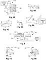
- Fig. 4B shows a simple one-dimensional network model for an infinite planar heat source whose power output is Q, which transfers heat to a node whose thermal capacitance is CW, and to an infinite sink at the duct air 420 temperature TD through a thermal resistance equal to that of the deposit RC and the film resistance RF on the duct air side 420.
- the RC the quantity that is unknown, can be obtained by solving for the value of RC by fitting a plot (e.g. 430 corresponding to a high value of RC or 432 corresponding to a low value of RC) of the measured temperatures to the unsteady model (t indicating time).
- Fig. 6 shows an optical fouling detector 640 which has a plate 618 with an illumination source 606 and a light sensor 604.
- a driver/detector 600 powers the illumination source, for example a light emitting diode with a lens, such that the illumination source directs light in a direction normal to a detection surface 616 when no material is deposited on the surface.
- the illumination source for example a light emitting diode with a lens
- the illumination source directs light in a direction normal to a detection surface 616 when no material is deposited on the surface.
- light from the illumination source 606 is scattered in the material layer 612 and received by the light sensor 604 as indicated by scattered beam 610.
- the greater the thickness of the material layer 612 the greater the scattering and the more light is received by the light sensor 604.
- Figs. 7A and 7B show another type of optical fouling detector 822 in which a light source 802 directs light such that it does not fall on a detector 806 when the surface of a lens or window 804 is clean, as indicated by arrows (representing beams) 808.
- arrows depict beams
- a driver/detector (not shown) functions as in the embodiment of Fig. 6 , generating an indication of a predefined degree of fouling after the quantity of light falling on the detector 806 reaches a threshold.
- a support 814 can hold both the light source 802 and the detector 806 in position within the duct.
- the detector 822 may be constructed of low cost materials and design such that it can be replaced each time the duct is cleaned. Thus, the device 822 generates a single indication and then is replaced.
- the driver/detector associated with it may be a permanent component.
- a disposable detector may be preferable to avoid the consequences of improper cleaning or change in performance characteristics of the fouling detector over time. All of the discussed embodiments may include single-use disposable components as discussed with regard to Figs. 7A and 7B .
- a light intensity curve can be obtained and memorized over time and compared with a representative profile for a detection surface that has become fouled.
- a representative profile may be one where the light intensity on the detector reaches a peak at a certain point in time and then decays due to further blocking by the deposited material.
- the fouling detection indication may be generated by detecting the peak or, in addition, after a drop in the light intensity that follows it of a certain amount.
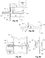
- Fig. 10a shows an example of a fouling detector 1000 employing a lever 1004 with a sensor 1008 that can indicate the accumulation of grease on a detection surface 1018 by deflection of the free end 1020.
- the lever 1004 is rotatably fixed at pivot point 1012.
- a spring 1010 is provided about pivot point 1012 and adjusted to hold the lever in a parallel orientation when no grease has accumulated on the lever.
- Support 1014 holds the lever 1004 via pivot point 1012 and spring 1010 at a fixed position with respect to duct wall 1002.
- the increased mass of the lever 1004 causes the lever to rotate about pivot 1012 in a counter-clockwise manner.
- a sensor 1008 may be provided in contact with the lever 1004 at a position outside of duct wall 1002.
- the sensor 1008 may be a strain gauge.
- sensor 1008 may be a force sensor.
- sensor 1008 may be a displacement sensor, such as a capacitive sensor.
- the sensor 1008 generates a signal indicative of movement of the lever due to the additional mass of the accumulated grease on the detection surface 1018.
- the controller 1016 may then use the signal to determine a fouling condition of the duct, such as the amount of grease accumulated on the detection surface.
- the strain gauge 1054 thus generates a signal indicative of the degree of bending of the cantilever due to the additional mass of the accumulated grease on the detection surface 1060.
- a controller 1058 may then use the signal to determine a fouling condition of the duct, such as the amount of grease accumulated on the detection surface.
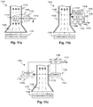
- Fig. 11a shows a generalized schematic 1100 of a fouling detector arrangement 1108.
- An air conveyance 1102 such as an exhaust duct, is used to carry an exhaust stream 1106 from a source of contamination 1104, such as a cooking appliance.
- Exhaust stream 1106 may carry aerosols, such as grease aerosols, which may be deposited on interior surfaces of the air conveyance 1102.
- a fouling detector arrangement 1108 may be provided to detect the deposition of aerosols or other pollutants.
- fouling detector arrangement 1108 may include a sensing element 1110 and a controller 1112.
- Sensing element 1110 may be disposed within the exhaust stream 1106 in air conveyance 1102 to allow aerosols or pollutants to interact therewith.
- sensing element 1110 may have a detection surface exposed to the exhaust stream 1106 which accumulates aerosols and/or pollutants resulting in a change in a property of the detection surface.
- Controller 1112 may be functionally connected to the sensing element 1110.
- the controller 1112 may interrogate the sensing element 1110 to obtain a measurement indicative of the level of accumulated aerosol and/or pollutants within the duct.
- controller 1112 may interrogate sensing element 1110 to determine a change in mass of the detection surface.
- Controller 1112 may also be configured to provide a subsequent output 1114 based on the interrogation.
- controller 1112 may activate an alarm system if the amount of accumulated contamination exceeds a predetermined threshold.
- Controller 1112 may also display a level of accumulated contamination to a user.
- Controller 1112 may also provide an output 1114 to other systems, such as an automatic air conveyance cleaning system to provide for cleaning of the air conveyance 1102 when accumulated contamination levels reach a predetermined threshold.
- the source 1134 interrogates the surface of the air conveyance 1102 by generating a signal 1136 and the sensing element 1138 measures the result 1140 of the interrogation to determine the amount of contaminant accumulated on the surface of the air conveyance 1102.
- source 1134 may be a source of acoustic or electromagnetic radiation.
- the radiation is modified in some form and measured by the sensing element 1138.
- both the source 1134 and sensing element 1138 may be located on the same side of the air conveyance 1102 and preferably oriented such that radiation emanating from the source 1134 and modified by the air conveyance 1102 can be received by sensing element 1138.
- Controller 1142 may be functionally connected to the sensing element 1138 and may use the measurement of the sensing element to determine a level of accumulated contaminants within the air conveyance 1106. Similar to controller 1112 in Fig. 11a , controller 1142 may also be configured to provide a subsequent output 1144 based on the determination of the level of accumulated contaminants.
- the source 1134 may be an electromagnetic radiation source, such as an infrared (IR) transmitter, and the sensing element 1138 may be an electromagnetic radiation sensor.
- the IR transmitter may generate an IR signal.
- the IR signal interacts with the air conveyance and is reflected and/or absorbed by the materials it encounters. A first reflection occurs at the external surface of the air conveyance. A second reflection occurs at the internal surface of the air conveyance. A third reflection occurs at the surface of the contamination layer accumulated on the internal surface of the air conveyance.
- the reflected signals are received by the electromagnetic radiation sensor. The controller may then use the received reflected signals to calculate the thickness of the deposited layer.
- the source 1166 interrogates the surfaces of the air conveyance 1102 by generating a signal 1170 and the sensing element 1164 measures the signal 1170, as modified by the air conveyance 1102, to determine the amount of contaminant accumulated on the surface of the air conveyance 1102.
- source 1166 may be a source of acoustic or electromagnetic radiation. The radiation is modified in some form and measured by the sensing element 1164. Note that both the source 1166 and sensing element 1164 are located opposite each other and preferably oriented such that radiation emanating from the source 1166 and modified by the air conveyance 1102 can be received by sensing element 1164.
Claims (4)
- Détecteur d'encrassement destiné à détecter un encrassement dû à la graisse déposé sur une surface intérieure d'un conduit d'évacuation qui évacue les vapeurs de cuisson d'une cuisine, comprenant :un élément destiné à être placé sur une surface dans un flux d'évacuation,la surface de l'élément présentant, ou étant, un miroir (958) ou un réflecteur diffus ;une source de lumière (960) configurée pour diriger une lumière vers la surface de l'élément ; etun détecteur (962) configuré pour recevoir la lumière réfléchie par la surface de l'élément,caractérisé en ce quel'élément est accouplé à la source de lumière et au détecteur par un bras qui présente un profil bas (959), de telle sorte que l'évacuation puisse s'écouler autour de l'élément en provoquant facilement un dépôt de matériau dans l'évacuation sur la surface de l'élément,où le détecteur d'encrassement est configuré afin d'être placé dans une seule ouverture d'accès d'une paroi du conduit (966).
- Détecteur d'encrassement selon la revendication 1, caractérisé par un dispositif de génération de signal configuré pour indiquer un état encrassé de la surface suite à un changement d'une propriété de la surface indicative d'un encrassement, dans lequel la propriété est une réflectivité.
- Détecteur d'encrassement selon l'une quelconque des revendications précédentes, comprenant en outre un mécanisme de refroidissement actif (956).
- Détecteur d'encrassement selon l'une quelconque des revendications précédentes, comprenant en outre un contrôleur, et dans lequel le contrôleur est configuré de façon à pouvoir être utilisé pour prendre une mesure d'échantillon quand un système d'évacuation ne fonctionne pas.
Priority Applications (1)
| Application Number | Priority Date | Filing Date | Title |
|---|---|---|---|
| PL13177388T PL2669651T3 (pl) | 2007-06-13 | 2008-06-13 | Detektor zanieczyszczeń do wykrywania zanieczyszczeń tłuszczem w przewodzie |
Applications Claiming Priority (3)
| Application Number | Priority Date | Filing Date | Title |
|---|---|---|---|
| US94362607P | 2007-06-13 | 2007-06-13 | |
| EP08771092.7A EP2165172B1 (fr) | 2007-06-13 | 2008-06-13 | Dispositifs de détection de dépôt de graisse dans une canalisation, systèmes et procédés |
| PCT/US2008/067000 WO2008157418A1 (fr) | 2007-06-13 | 2008-06-13 | Dispositifs de détection de dépôt de graisse dans une canalisation, systèmes et procédés |
Related Parent Applications (3)
| Application Number | Title | Priority Date | Filing Date |
|---|---|---|---|
| EP08771092.7 Division | 2008-06-13 | ||
| EP08771092.7A Division-Into EP2165172B1 (fr) | 2007-06-13 | 2008-06-13 | Dispositifs de détection de dépôt de graisse dans une canalisation, systèmes et procédés |
| EP08771092.7A Division EP2165172B1 (fr) | 2007-06-13 | 2008-06-13 | Dispositifs de détection de dépôt de graisse dans une canalisation, systèmes et procédés |
Publications (3)
| Publication Number | Publication Date |
|---|---|
| EP2669651A2 EP2669651A2 (fr) | 2013-12-04 |
| EP2669651A3 EP2669651A3 (fr) | 2013-12-11 |
| EP2669651B1 true EP2669651B1 (fr) | 2020-12-09 |
Family
ID=40156640
Family Applications (2)
| Application Number | Title | Priority Date | Filing Date |
|---|---|---|---|
| EP13177388.9A Active EP2669651B1 (fr) | 2007-06-13 | 2008-06-13 | Dispositif de détection d'encrassement pour la détection de dépôts de graisse dans une canalisation |
| EP08771092.7A Active EP2165172B1 (fr) | 2007-06-13 | 2008-06-13 | Dispositifs de détection de dépôt de graisse dans une canalisation, systèmes et procédés |
Family Applications After (1)
| Application Number | Title | Priority Date | Filing Date |
|---|---|---|---|
| EP08771092.7A Active EP2165172B1 (fr) | 2007-06-13 | 2008-06-13 | Dispositifs de détection de dépôt de graisse dans une canalisation, systèmes et procédés |
Country Status (11)
| Country | Link |
|---|---|
| US (3) | US8487776B2 (fr) |
| EP (2) | EP2669651B1 (fr) |
| JP (3) | JP2010530964A (fr) |
| AU (1) | AU2008265939C1 (fr) |
| BR (1) | BRPI0812733B1 (fr) |
| CA (1) | CA2690615C (fr) |
| DK (2) | DK2165172T3 (fr) |
| MX (1) | MX2009013598A (fr) |
| PL (2) | PL2165172T3 (fr) |
| WO (1) | WO2008157418A1 (fr) |
| ZA (1) | ZA201000103B (fr) |
Families Citing this family (55)
| Publication number | Priority date | Publication date | Assignee | Title |
|---|---|---|---|---|
| CA2571268C (fr) | 2004-06-22 | 2010-05-18 | Oy Halton Group Ltd. | Controleur d'expulsion a pose facile |
| WO2006012628A2 (fr) | 2004-07-23 | 2006-02-02 | Halton Company | Regulation amelioree de systemes d'echappement |
| CA2793796C (fr) | 2006-04-18 | 2016-07-05 | Oy Halton Group, Ltd. | Unite murale modulaire comportant une petite hotte d'evacuation |
| US20080274683A1 (en) | 2007-05-04 | 2008-11-06 | Current Energy Controls, Lp | Autonomous Ventilation System |
| US20090061752A1 (en) | 2007-08-28 | 2009-03-05 | Current Energy Controls, Lp | Autonomous Ventilation System |
| GB0724779D0 (en) * | 2007-12-20 | 2008-01-30 | Vanguard Sensor Technologies L | Monitoring system |
| BRPI0910709B1 (pt) | 2008-04-18 | 2020-10-27 | Oy Halton Group Ltd | dispositivo de exaustão |
| DE102008048090B3 (de) * | 2008-09-19 | 2010-02-04 | Kornack-Cielewicz, Katja | Kanalsystem für Küchenabluft |
| MX2011005770A (es) | 2008-12-03 | 2011-08-15 | Halton Group Ltd Oy | Sistemas y metodo para el control del flujo de evacuacion. |
| US20120055275A1 (en) * | 2010-09-02 | 2012-03-08 | Streivor Air Systems, Inc. | System and Method for Smart Operation of an Exhaust Hood Using a Protected Monitoring Device |
| US9414024B2 (en) * | 2010-10-12 | 2016-08-09 | Enertechnix, Inc. | Terahertz imaging |
| MX2013006280A (es) | 2010-12-05 | 2013-08-01 | Halton Group Ltd Oy | Sistemas, metodos y dispositivos de monitoreo de luz ultravioleta. |
| GB2493354A (en) * | 2011-07-29 | 2013-02-06 | Prevent Systems Ltd | Detecting deposits build-up in a ventilation duct |
| BR112014015326B1 (pt) * | 2011-12-22 | 2020-12-15 | Solenis Technologies Cayman, L.P | Dispositivo e método para a detecção de depósitos |
| DE102012213692A1 (de) * | 2012-08-02 | 2014-02-06 | BSH Bosch und Siemens Hausgeräte GmbH | Dunstabzugsvorrichtung und Verfahren zum Ansteuerung eines Lüftermotors eines Lüfters und zur Luftreinigungswirkungsermittlung |
| FI124057B (fi) | 2012-12-05 | 2014-02-28 | Metso Power Oy | Järjestely termisessä prosessissa ja menetelmä likakerroksen paksuuden mittaamiseksi |
| US9151722B2 (en) * | 2014-01-15 | 2015-10-06 | King Abdulaziz University | Systems for determining and imaging wax deposition and simultaneous corrosion and wax deposit determination in pipelines |
| WO2015127547A1 (fr) * | 2014-02-27 | 2015-09-03 | Walter Surface Technologies Inc. | Méthodologie de mesure de la propreté industrielle |
| KR101679231B1 (ko) * | 2014-07-02 | 2016-12-06 | 주식회사 지오시스 | 상업용 주방화재 소화시스템 |
| WO2016089688A1 (fr) | 2014-12-01 | 2016-06-09 | 3M Innovative Properties Company | Systèmes et procédés de prédiction de changement de filtre hvac |
| JP6581855B2 (ja) * | 2015-09-08 | 2019-09-25 | 三菱日立パワーシステムズ株式会社 | 異物検査方法及び異物検査用治具 |
| CN105091059B (zh) * | 2015-09-12 | 2018-01-26 | 徐建立 | 油烟机清洗装置及其控制方法 |
| CN106051857A (zh) * | 2016-06-15 | 2016-10-26 | 广东美的厨房电器制造有限公司 | 油烟机及油烟机的清洗方法 |
| CN106111593A (zh) * | 2016-07-14 | 2016-11-16 | 广东美的厨房电器制造有限公司 | 控制进行污垢清洗的方法和装置 |
| KR101985531B1 (ko) * | 2016-08-01 | 2019-06-03 | 엘지전자 주식회사 | 필터 어셈블리, 이를 포함하는 공기 정화장치 및 그 제어방법 |
| WO2018156149A1 (fr) * | 2017-02-24 | 2018-08-30 | Ecolab Usa Inc. | Moniteur de dépôt thermoélectrique |
| JP6842955B2 (ja) * | 2017-03-13 | 2021-03-17 | 三菱電機株式会社 | 加熱調理器 |
| WO2018175495A1 (fr) * | 2017-03-20 | 2018-09-27 | Oy Halton Group Ltd. | Procédés et systèmes pour dispositifs de sécurité contre l'incendie |
| US20180304316A1 (en) * | 2017-04-21 | 2018-10-25 | Sebastien Khandjian | Systems and methods to clean ducts |
| CN107121302B (zh) * | 2017-06-12 | 2023-09-15 | 武汉黎赛科技有限责任公司 | 一种轮轨润滑综合检测装置及方法 |
| CN107366938B (zh) * | 2017-07-19 | 2019-01-18 | 珠海格力电器股份有限公司 | 一种空气净化设备及其控制方法和装置 |
| CN109916855B (zh) * | 2017-12-13 | 2021-08-20 | 宁波方太厨具有限公司 | 油烟传感器的数据处理方法 |
| CN108119985A (zh) * | 2017-12-21 | 2018-06-05 | 珠海格力电器股份有限公司 | 风道清洁方法、装置及空调 |
| KR102498059B1 (ko) * | 2017-12-28 | 2023-02-10 | (주)보부하이테크 | 배기관 내 부산물 측정 장치 모듈 및 부산물 측정 방법 |
| JP7155525B2 (ja) * | 2018-01-15 | 2022-10-19 | 日新電機株式会社 | 塵埃堆積検知装置 |
| CN111121115A (zh) * | 2018-10-30 | 2020-05-08 | 宁波方太厨具有限公司 | 一种蜗壳积油检测提醒方法 |
| US11953458B2 (en) * | 2019-03-14 | 2024-04-09 | Ecolab Usa Inc. | Systems and methods utilizing sensor surface functionalization |
| US11114286B2 (en) * | 2019-04-08 | 2021-09-07 | Applied Materials, Inc. | In-situ optical chamber surface and process sensor |
| CN110030722B (zh) * | 2019-04-23 | 2020-09-18 | 江苏华舜环境工程有限公司 | 一种节能环保的自清洁烟囱 |
| CN110131768A (zh) * | 2019-05-22 | 2019-08-16 | 张玉波 | 一种节能环保的螺旋式自清洁烟囱 |
| SE544067C2 (en) | 2019-06-26 | 2021-11-30 | Bioteria Tech Ab | Methods, system and device for controlling biological treatment processes and systems |
| US11320363B2 (en) | 2019-09-03 | 2022-05-03 | Halliburton Energy Services, Inc. | Treatment of pipeline deposits |
| CN110617526B (zh) * | 2019-09-25 | 2021-03-19 | 佛山市顺德区美的洗涤电器制造有限公司 | 厨房装置 |
| CN110617535B (zh) * | 2019-09-25 | 2021-03-19 | 佛山市顺德区美的洗涤电器制造有限公司 | 厨房装置 |
| CN110988972B (zh) * | 2019-10-12 | 2022-10-21 | 中国辐射防护研究院 | 高精度三维便携式表面污染仪检定装置 |
| US11499869B2 (en) * | 2019-11-13 | 2022-11-15 | Applied Materials, Inc. | Optical wall and process sensor with plasma facing sensor |
| JP2022023372A (ja) * | 2020-07-27 | 2022-02-08 | 株式会社アガタ | 閉空間監視装置 |
| CN112147030A (zh) * | 2020-09-26 | 2020-12-29 | 国网山东省电力公司电力科学研究院 | 外绝缘部件污秽沉积量检测装置及方法 |
| CN114017397A (zh) * | 2021-11-29 | 2022-02-08 | 广东万和电气有限公司 | 风机组件的清洗方法以及烟机 |
| CN114234251B (zh) * | 2021-12-17 | 2023-07-25 | 杭州老板电器股份有限公司 | 烟机的烟道状态识别方法和装置 |
| CN114543687A (zh) * | 2022-01-07 | 2022-05-27 | 山东山消智慧安全科技有限公司 | 一种烟道油垢厚度监测系统和方法 |
| CN115032123A (zh) * | 2022-03-21 | 2022-09-09 | 哈尔滨工程大学 | 一种研究不同热工条件下管道内气溶胶沉积特性的实验装置 |
| CN115541438B (zh) * | 2022-12-02 | 2023-05-02 | 山东理工职业学院 | 一种便携式多环境大气环境污染检测仪及其使用方法 |
| CN116592774B (zh) * | 2023-07-18 | 2023-09-19 | 成都洋湃科技有限公司 | 管壁污垢检测方法、装置、存储介质及电子设备 |
| CN116753873B (zh) * | 2023-08-14 | 2023-10-27 | 成都顿威新型金属材料有限公司 | 一种复合锂带厚度检测装置及方法 |
Citations (3)
| Publication number | Priority date | Publication date | Assignee | Title |
|---|---|---|---|---|
| JPS60140037A (ja) * | 1983-12-27 | 1985-07-24 | Matsushita Electric Ind Co Ltd | 排煙装置 |
| JPH0979979A (ja) * | 1995-09-13 | 1997-03-28 | Toyota Motor Corp | 内燃機関のスモーク濃度検出装置 |
| JPH10170438A (ja) * | 1996-12-13 | 1998-06-26 | Nippon Winton Kk | 空調ダクト内の粉塵検知装置及び汚染度判別方法 |
Family Cites Families (52)
| Publication number | Priority date | Publication date | Assignee | Title |
|---|---|---|---|---|
| GB815347A (en) | 1957-02-22 | 1959-06-24 | Plinio Piacentini | Improvements in traffic signals |
| GB815366A (en) | 1955-09-14 | 1959-06-24 | British Thomson Houston Co Ltd | Improvements in and relating to electrical control systems |
| GB724779A (en) | 1953-01-14 | 1955-02-23 | John Tomkins | An apparatus for sealing envelopes |
| US3023312A (en) * | 1957-10-03 | 1962-02-27 | Tuboscope Company | Radioactive pipe thickness measurement |
| US3810009A (en) * | 1971-10-06 | 1974-05-07 | Universal Oil Prod Co | Apparatus for measuring material fouling of a test specimen |
| US3890827A (en) * | 1973-08-23 | 1975-06-24 | Cylpik Inc | Method and apparatus for monitoring grease buildup within an exhaust system |
| JPS5373168A (en) * | 1976-12-13 | 1978-06-29 | Hokushin Gohan Kk | Measuring method and apparatus for weight of powdered articles in wind sending process |
| GB2077426B (en) | 1980-05-30 | 1983-12-14 | Fuji Electric Co Ltd | Apparatus for measuring film thickness |
| DE3030499C2 (de) * | 1980-08-12 | 1982-05-27 | Siemens AG, 1000 Berlin und 8000 München | Anordnung zur Feststellung von Partikeln in einer Gasströmung |
| US4524835A (en) | 1981-01-30 | 1985-06-25 | Mingrone Frank V | Fire suppression systems |
| JPS6033143U (ja) | 1983-08-11 | 1985-03-06 | 株式会社長谷工コーポレーション | 換気扇 |
| JPS6325359U (fr) * | 1986-08-04 | 1988-02-19 | ||
| US4912332A (en) * | 1988-06-03 | 1990-03-27 | Research And Development Institute, Inc. At Montana State University | Non-destructive methods for detecting organic deposits and removing them |
| IE70325B1 (en) * | 1989-05-15 | 1996-11-13 | Akzo Nv | Apparatus for detection of microorganisms |
| US5112642A (en) * | 1990-03-30 | 1992-05-12 | Leybold Inficon, Inc. | Measuring and controlling deposition on a piezoelectric monitor crystal |
| US5096502A (en) * | 1990-12-03 | 1992-03-17 | The Babcock & Wilcox Company | Advanced water lance control system based on peak furnace wall emissivity |
| JP3399040B2 (ja) | 1993-09-20 | 2003-04-21 | 株式会社日立製作所 | 半導体製造装置及び半導体製造方法 |
| JPH07134089A (ja) * | 1993-11-09 | 1995-05-23 | Toyota Motor Corp | 塗料ミスト検知方法 |
| ES2124011T3 (es) * | 1994-08-23 | 1999-01-16 | Foster Wheeler Energia Oy | Procedimiento de funcionamiento de un sistema reactor de lecho fluidizado y sistema asociado. |
| GB9419886D0 (en) | 1994-10-03 | 1994-11-16 | Boc Group Plc | 0 161194 GB 9419886A 031094 GB 9419886A 031094Device for monitoring deposits in a pipe or vessel |
| DE19510304C1 (de) | 1995-03-22 | 1996-02-01 | Leuze Electronic Gmbh & Co | Lichtschrankengitter |
| US5985032A (en) * | 1995-05-17 | 1999-11-16 | Matsushita Electric Industrial Co., Ltd. | Semiconductor manufacturing apparatus |
| US5843232A (en) * | 1995-11-02 | 1998-12-01 | General Electric Company | Measuring deposit thickness in composite materials production |
| US5661233A (en) * | 1996-03-26 | 1997-08-26 | Sandia Corporation | Acoustic-wave sensor apparatus for analyzing a petroleum-based composition and sensing solidification of constituents therein |
| US5666394A (en) * | 1996-04-23 | 1997-09-09 | Northrop Grumman Corporation | Thickness measurement gauge |
| US6025916A (en) * | 1997-02-27 | 2000-02-15 | Wisconsin Alumni Research Foundation | Wall deposition thickness sensor for plasma processing chamber |
| FR2760531B1 (fr) * | 1997-03-07 | 1999-04-16 | Inst Francais Du Petrole | Dispositif destine a detecter l'encrassement et a chauffer localement un milieu isolant |
| JP3525033B2 (ja) * | 1997-07-07 | 2004-05-10 | シャープ株式会社 | 自動換気機能付空気調和装置 |
| US6170480B1 (en) * | 1999-01-22 | 2001-01-09 | Melink Corporation | Commercial kitchen exhaust system |
| US6124927A (en) * | 1999-05-19 | 2000-09-26 | Chartered Semiconductor Manufacturing Ltd. | Method to protect chamber wall from etching by endpoint plasma clean |
| GB9925373D0 (en) * | 1999-10-27 | 1999-12-29 | Schlumberger Ltd | Downhole instrumentation and cleaning system |
| US6536649B1 (en) * | 2000-07-28 | 2003-03-25 | Advanced Micro Devices, Inc. | Method of preventing residue contamination of semiconductor devices during furnace processing |
| JP2002286636A (ja) * | 2001-01-19 | 2002-10-03 | Advantest Corp | 化学物質検出方法及び装置 |
| US6513385B1 (en) * | 2001-05-08 | 2003-02-04 | Halliburton Energy Services, Inc. | Acoustic sensor for pipeline deposition characterization and monitoring |
| TW552188B (en) * | 2001-11-16 | 2003-09-11 | Towa Corp | Apparatus and method for evaluating degree of adhesion of adherents to mold surface, apparatus and method for surface treatment of mold surface and method and apparatus for cleaning mold used for molding resin |
| JP3735293B2 (ja) * | 2001-11-21 | 2006-01-18 | 三菱重工業株式会社 | 海塩粒子モニタリング方法、海塩粒子洗浄モニタリング方法、および海塩粒子洗浄モニタリング装置 |
| GB0128704D0 (en) * | 2001-11-30 | 2002-01-23 | Univ Manchester | Remote pipeline inspection |
| EP1318211B1 (fr) | 2001-12-07 | 2008-08-27 | Infineon Technologies SC300 GmbH & Co. KG | Système de surveillance de l'épaisseur d'une couche se déposant sur les parois d'une chambre de traitement |
| US7354429B2 (en) * | 2003-05-27 | 2008-04-08 | Integrated Sensing Systems, Inc. | Device and method for detecting and treating chemical and biological agents |
| US20040231400A1 (en) * | 2003-05-19 | 2004-11-25 | Bradenbaugh Kenneth A. | Method and apparatus for detecting accumulation of particulate matter from a flowing air stream |
| DE10351254A1 (de) * | 2003-11-03 | 2005-06-02 | Adc Automotive Distance Control Systems Gmbh | Vorrichtung zur Erfassung von Verschmutzungen auf einer lichtdurchlässigen Abdeckscheibe vor einem optischen Einheit |
| US7178410B2 (en) * | 2004-03-22 | 2007-02-20 | Cleanalert, Llc | Clogging detector for air filter |
| JP4025308B2 (ja) * | 2004-03-31 | 2007-12-19 | 株式会社山武 | 鏡面冷却式センサ |
| DE102004029524B4 (de) * | 2004-06-18 | 2007-12-06 | Robert Bosch Gmbh | Verfahren und Vorrichtung zur definierten Regeneration von rußbehafteten Oberflächen |
| US7866211B2 (en) * | 2004-07-16 | 2011-01-11 | Rosemount Inc. | Fouling and corrosion detector for process control industries |
| US7741108B2 (en) * | 2005-01-14 | 2010-06-22 | Optech Ventures, Llc | Bacteria sensor and method |
| DE102005041004A1 (de) * | 2005-08-29 | 2007-03-01 | Cmv Systems Gmbh & Co.Kg | Verfahren und Vorrichtung zur Überwachung der Bildung von Ansätzen in Feuerräumen |
| EP1987319B1 (fr) | 2006-02-13 | 2018-04-11 | Solenis Technologies Cayman, L.P. | Systeme de mesure pour l'acquisition de l'epaisseur de couche d'un depot |
| US20070189356A1 (en) * | 2006-02-13 | 2007-08-16 | Jonathan Pettit | Exhaust buildup monitoring in semiconductor processing |
| US7465332B2 (en) * | 2006-04-21 | 2008-12-16 | Gemchar, Llc | Disposable grease filter for air filtration system and method of manufacturing same |
| US20080100826A1 (en) * | 2006-10-26 | 2008-05-01 | Richard Sharpe | Devices For Monitoring Particulate Accumulation On A Filter And Related Methods |
| GB0724779D0 (en) | 2007-12-20 | 2008-01-30 | Vanguard Sensor Technologies L | Monitoring system |
-
2008
- 2008-06-13 EP EP13177388.9A patent/EP2669651B1/fr active Active
- 2008-06-13 WO PCT/US2008/067000 patent/WO2008157418A1/fr active Application Filing
- 2008-06-13 PL PL08771092T patent/PL2165172T3/pl unknown
- 2008-06-13 JP JP2010512404A patent/JP2010530964A/ja active Pending
- 2008-06-13 AU AU2008265939A patent/AU2008265939C1/en active Active
- 2008-06-13 DK DK08771092.7T patent/DK2165172T3/en active
- 2008-06-13 US US12/664,369 patent/US8487776B2/en active Active
- 2008-06-13 EP EP08771092.7A patent/EP2165172B1/fr active Active
- 2008-06-13 BR BRPI0812733A patent/BRPI0812733B1/pt active IP Right Grant
- 2008-06-13 CA CA2690615A patent/CA2690615C/fr active Active
- 2008-06-13 DK DK13177388.9T patent/DK2669651T3/da active
- 2008-06-13 PL PL13177388T patent/PL2669651T3/pl unknown
- 2008-06-13 MX MX2009013598A patent/MX2009013598A/es active IP Right Grant
-
2010
- 2010-01-06 ZA ZA2010/00103A patent/ZA201000103B/en unknown
-
2012
- 2012-11-12 JP JP2012248262A patent/JP5868307B2/ja active Active
-
2013
- 2013-06-09 US US13/913,484 patent/US20130271748A1/en not_active Abandoned
-
2014
- 2014-07-07 US US14/324,981 patent/US20140318284A1/en not_active Abandoned
- 2014-09-30 JP JP2014201251A patent/JP2014240750A/ja active Pending
Patent Citations (3)
| Publication number | Priority date | Publication date | Assignee | Title |
|---|---|---|---|---|
| JPS60140037A (ja) * | 1983-12-27 | 1985-07-24 | Matsushita Electric Ind Co Ltd | 排煙装置 |
| JPH0979979A (ja) * | 1995-09-13 | 1997-03-28 | Toyota Motor Corp | 内燃機関のスモーク濃度検出装置 |
| JPH10170438A (ja) * | 1996-12-13 | 1998-06-26 | Nippon Winton Kk | 空調ダクト内の粉塵検知装置及び汚染度判別方法 |
Also Published As
| Publication number | Publication date |
|---|---|
| PL2669651T3 (pl) | 2021-10-25 |
| AU2008265939C1 (en) | 2013-11-21 |
| EP2165172B1 (fr) | 2017-04-19 |
| US20100225477A1 (en) | 2010-09-09 |
| CA2690615C (fr) | 2017-07-18 |
| DK2669651T3 (da) | 2021-02-22 |
| US20140318284A1 (en) | 2014-10-30 |
| BRPI0812733A2 (pt) | 2014-12-23 |
| CA2690615A1 (fr) | 2008-12-24 |
| AU2008265939B2 (en) | 2013-05-23 |
| EP2669651A3 (fr) | 2013-12-11 |
| JP2013083654A (ja) | 2013-05-09 |
| EP2165172A4 (fr) | 2010-07-21 |
| WO2008157418A1 (fr) | 2008-12-24 |
| AU2008265939A1 (en) | 2008-12-24 |
| JP5868307B2 (ja) | 2016-02-24 |
| PL2165172T3 (pl) | 2017-09-29 |
| EP2669651A2 (fr) | 2013-12-04 |
| JP2014240750A (ja) | 2014-12-25 |
| JP2010530964A (ja) | 2010-09-16 |
| US20130271748A1 (en) | 2013-10-17 |
| MX2009013598A (es) | 2010-01-26 |
| BRPI0812733B1 (pt) | 2019-01-29 |
| DK2165172T3 (en) | 2017-07-17 |
| EP2165172A1 (fr) | 2010-03-24 |
| ZA201000103B (en) | 2015-08-26 |
| US8487776B2 (en) | 2013-07-16 |
Similar Documents
| Publication | Publication Date | Title |
|---|---|---|
| EP2669651B1 (fr) | Dispositif de détection d'encrassement pour la détection de dépôts de graisse dans une canalisation | |
| US10083589B2 (en) | Method and device for monitoring a protective glass | |
| US20070147467A1 (en) | Apparatus and Method for Measuring a Condensable Component of a Gas Sample | |
| CN112638480A (zh) | 支持传感器的抽油烟机 | |
| EP3511914A1 (fr) | Moniteurs de qualité de l'air sans chambre avec détection de température | |
| WO2018076405A1 (fr) | Dispositif de mesure de poussière | |
| JP5852834B2 (ja) | 微粒子検出装置の評価システム及び微粒子検出装置の評価方法 | |
| CN106442249B (zh) | 粉尘检测装置 | |
| EP3907714B1 (fr) | Prévention contre la condensation dans un système de détection de fumée aspirée | |
| JP5875823B2 (ja) | 環境提供装置、環境提供方法、及び微粒子検出装置の評価方法 | |
| JPH05231683A (ja) | レンジフード及び換気装置 | |
| CN106290098B (zh) | 粉尘检测装置 | |
| JP6829784B2 (ja) | 煙感知器、及び煙濃度推定方法 | |
| EP3658890B1 (fr) | Système de contrôle de la qualité de l'air dans des conduites d'air | |
| Ghaderi et al. | Self-Cleaning Micro-Windows for In-Tailpipe Optical Exhaust Gas Measurements | |
| JP2010025886A (ja) | すす濃度測定装置 | |
| Golinelli et al. | Diffraction based optical particle sizer for on-line monitoring in hostile environments of low concentration particle laden flows | |
| Kuhn | An instrument for monitoring number and mass of ambient particles in coarse, fine and ultrafine size ranges | |
| JPS62225927A (ja) | 粒子計測方法 |
Legal Events
| Date | Code | Title | Description |
|---|---|---|---|
| PUAL | Search report despatched |
Free format text: ORIGINAL CODE: 0009013 |
|
| PUAI | Public reference made under article 153(3) epc to a published international application that has entered the european phase |
Free format text: ORIGINAL CODE: 0009012 |
|
| AC | Divisional application: reference to earlier application |
Ref document number: 2165172 Country of ref document: EP Kind code of ref document: P |
|
| AK | Designated contracting states |
Kind code of ref document: A2 Designated state(s): AT BE BG CH CY CZ DE DK EE ES FI FR GB GR HR HU IE IS IT LI LT LU LV MC MT NL NO PL PT RO SE SI SK TR |
|
| AK | Designated contracting states |
Kind code of ref document: A3 Designated state(s): AT BE BG CH CY CZ DE DK EE ES FI FR GB GR HR HU IE IS IT LI LT LU LV MC MT NL NO PL PT RO SE SI SK TR |
|
| RIC1 | Information provided on ipc code assigned before grant |
Ipc: F23J 3/02 20060101ALI20131106BHEP Ipc: G01N 1/00 20060101AFI20131106BHEP Ipc: F24C 15/20 20060101ALI20131106BHEP Ipc: G01N 21/55 20060101ALI20131106BHEP Ipc: F23N 5/24 20060101ALI20131106BHEP |
|
| 17P | Request for examination filed |
Effective date: 20140611 |
|
| RBV | Designated contracting states (corrected) |
Designated state(s): AT BE BG CH CY CZ DE DK EE ES FI FR GB GR HR HU IE IS IT LI LT LU LV MC MT NL NO PL PT RO SE SI SK TR |
|
| REG | Reference to a national code |
Ref country code: HK Ref legal event code: DE Ref document number: 1192777 Country of ref document: HK |
|
| STAA | Information on the status of an ep patent application or granted ep patent |
Free format text: STATUS: EXAMINATION IS IN PROGRESS |
|
| 17Q | First examination report despatched |
Effective date: 20180727 |
|
| GRAP | Despatch of communication of intention to grant a patent |
Free format text: ORIGINAL CODE: EPIDOSNIGR1 |
|
| STAA | Information on the status of an ep patent application or granted ep patent |
Free format text: STATUS: GRANT OF PATENT IS INTENDED |
|
| INTG | Intention to grant announced |
Effective date: 20200605 |
|
| GRAJ | Information related to disapproval of communication of intention to grant by the applicant or resumption of examination proceedings by the epo deleted |
Free format text: ORIGINAL CODE: EPIDOSDIGR1 |
|
| STAA | Information on the status of an ep patent application or granted ep patent |
Free format text: STATUS: EXAMINATION IS IN PROGRESS |
|
| GRAR | Information related to intention to grant a patent recorded |
Free format text: ORIGINAL CODE: EPIDOSNIGR71 |
|
| GRAS | Grant fee paid |
Free format text: ORIGINAL CODE: EPIDOSNIGR3 |
|
| STAA | Information on the status of an ep patent application or granted ep patent |
Free format text: STATUS: GRANT OF PATENT IS INTENDED |
|
| GRAA | (expected) grant |
Free format text: ORIGINAL CODE: 0009210 |
|
| STAA | Information on the status of an ep patent application or granted ep patent |
Free format text: STATUS: THE PATENT HAS BEEN GRANTED |
|
| INTC | Intention to grant announced (deleted) | ||
| AC | Divisional application: reference to earlier application |
Ref document number: 2165172 Country of ref document: EP Kind code of ref document: P |
|
| AK | Designated contracting states |
Kind code of ref document: B1 Designated state(s): AT BE BG CH CY CZ DE DK EE ES FI FR GB GR HR HU IE IS IT LI LT LU LV MC MT NL NO PL PT RO SE SI SK TR |
|
| INTG | Intention to grant announced |
Effective date: 20201102 |
|
| RAP1 | Party data changed (applicant data changed or rights of an application transferred) |
Owner name: OY HALTON GROUP, LTD. |
|
| REG | Reference to a national code |
Ref country code: GB Ref legal event code: FG4D |
|
| REG | Reference to a national code |
Ref country code: AT Ref legal event code: REF Ref document number: 1343922 Country of ref document: AT Kind code of ref document: T Effective date: 20201215 Ref country code: CH Ref legal event code: EP |
|
| REG | Reference to a national code |
Ref country code: DE Ref legal event code: R096 Ref document number: 602008063562 Country of ref document: DE |
|
| REG | Reference to a national code |
Ref country code: IE Ref legal event code: FG4D |
|
| REG | Reference to a national code |
Ref country code: CH Ref legal event code: NV Representative=s name: E. BLUM AND CO. AG PATENT- UND MARKENANWAELTE , CH |
|
| REG | Reference to a national code |
Ref country code: DK Ref legal event code: T3 Effective date: 20210217 Ref country code: FI Ref legal event code: FGE |
|
| REG | Reference to a national code |
Ref country code: SE Ref legal event code: TRGR |
|
| REG | Reference to a national code |
Ref country code: NL Ref legal event code: FP |
|
| PG25 | Lapsed in a contracting state [announced via postgrant information from national office to epo] |
Ref country code: GR Free format text: LAPSE BECAUSE OF FAILURE TO SUBMIT A TRANSLATION OF THE DESCRIPTION OR TO PAY THE FEE WITHIN THE PRESCRIBED TIME-LIMIT Effective date: 20210310 |
|
| REG | Reference to a national code |
Ref country code: NO Ref legal event code: T2 Effective date: 20201209 |
|
| PG25 | Lapsed in a contracting state [announced via postgrant information from national office to epo] |
Ref country code: LV Free format text: LAPSE BECAUSE OF FAILURE TO SUBMIT A TRANSLATION OF THE DESCRIPTION OR TO PAY THE FEE WITHIN THE PRESCRIBED TIME-LIMIT Effective date: 20201209 Ref country code: BG Free format text: LAPSE BECAUSE OF FAILURE TO SUBMIT A TRANSLATION OF THE DESCRIPTION OR TO PAY THE FEE WITHIN THE PRESCRIBED TIME-LIMIT Effective date: 20210309 |
|
| PG25 | Lapsed in a contracting state [announced via postgrant information from national office to epo] |
Ref country code: HR Free format text: LAPSE BECAUSE OF FAILURE TO SUBMIT A TRANSLATION OF THE DESCRIPTION OR TO PAY THE FEE WITHIN THE PRESCRIBED TIME-LIMIT Effective date: 20201209 |
|
| REG | Reference to a national code |
Ref country code: LT Ref legal event code: MG9D |
|
| PG25 | Lapsed in a contracting state [announced via postgrant information from national office to epo] |
Ref country code: PT Free format text: LAPSE BECAUSE OF FAILURE TO SUBMIT A TRANSLATION OF THE DESCRIPTION OR TO PAY THE FEE WITHIN THE PRESCRIBED TIME-LIMIT Effective date: 20210409 Ref country code: SK Free format text: LAPSE BECAUSE OF FAILURE TO SUBMIT A TRANSLATION OF THE DESCRIPTION OR TO PAY THE FEE WITHIN THE PRESCRIBED TIME-LIMIT Effective date: 20201209 Ref country code: RO Free format text: LAPSE BECAUSE OF FAILURE TO SUBMIT A TRANSLATION OF THE DESCRIPTION OR TO PAY THE FEE WITHIN THE PRESCRIBED TIME-LIMIT Effective date: 20201209 Ref country code: LT Free format text: LAPSE BECAUSE OF FAILURE TO SUBMIT A TRANSLATION OF THE DESCRIPTION OR TO PAY THE FEE WITHIN THE PRESCRIBED TIME-LIMIT Effective date: 20201209 Ref country code: EE Free format text: LAPSE BECAUSE OF FAILURE TO SUBMIT A TRANSLATION OF THE DESCRIPTION OR TO PAY THE FEE WITHIN THE PRESCRIBED TIME-LIMIT Effective date: 20201209 Ref country code: CZ Free format text: LAPSE BECAUSE OF FAILURE TO SUBMIT A TRANSLATION OF THE DESCRIPTION OR TO PAY THE FEE WITHIN THE PRESCRIBED TIME-LIMIT Effective date: 20201209 |
|
| REG | Reference to a national code |
Ref country code: DE Ref legal event code: R097 Ref document number: 602008063562 Country of ref document: DE |
|
| PG25 | Lapsed in a contracting state [announced via postgrant information from national office to epo] |
Ref country code: IS Free format text: LAPSE BECAUSE OF FAILURE TO SUBMIT A TRANSLATION OF THE DESCRIPTION OR TO PAY THE FEE WITHIN THE PRESCRIBED TIME-LIMIT Effective date: 20210409 |
|
| PLBE | No opposition filed within time limit |
Free format text: ORIGINAL CODE: 0009261 |
|
| STAA | Information on the status of an ep patent application or granted ep patent |
Free format text: STATUS: NO OPPOSITION FILED WITHIN TIME LIMIT |
|
| 26N | No opposition filed |
Effective date: 20210910 |
|
| PG25 | Lapsed in a contracting state [announced via postgrant information from national office to epo] |
Ref country code: ES Free format text: LAPSE BECAUSE OF FAILURE TO SUBMIT A TRANSLATION OF THE DESCRIPTION OR TO PAY THE FEE WITHIN THE PRESCRIBED TIME-LIMIT Effective date: 20201209 Ref country code: SI Free format text: LAPSE BECAUSE OF FAILURE TO SUBMIT A TRANSLATION OF THE DESCRIPTION OR TO PAY THE FEE WITHIN THE PRESCRIBED TIME-LIMIT Effective date: 20201209 |
|
| PG25 | Lapsed in a contracting state [announced via postgrant information from national office to epo] |
Ref country code: MC Free format text: LAPSE BECAUSE OF FAILURE TO SUBMIT A TRANSLATION OF THE DESCRIPTION OR TO PAY THE FEE WITHIN THE PRESCRIBED TIME-LIMIT Effective date: 20201209 |
|
| REG | Reference to a national code |
Ref country code: BE Ref legal event code: MM Effective date: 20210630 |
|
| PG25 | Lapsed in a contracting state [announced via postgrant information from national office to epo] |
Ref country code: LU Free format text: LAPSE BECAUSE OF NON-PAYMENT OF DUE FEES Effective date: 20210613 |
|
| PG25 | Lapsed in a contracting state [announced via postgrant information from national office to epo] |
Ref country code: IE Free format text: LAPSE BECAUSE OF NON-PAYMENT OF DUE FEES Effective date: 20210613 |
|
| PG25 | Lapsed in a contracting state [announced via postgrant information from national office to epo] |
Ref country code: IS Free format text: LAPSE BECAUSE OF FAILURE TO SUBMIT A TRANSLATION OF THE DESCRIPTION OR TO PAY THE FEE WITHIN THE PRESCRIBED TIME-LIMIT Effective date: 20210409 |
|
| PG25 | Lapsed in a contracting state [announced via postgrant information from national office to epo] |
Ref country code: BE Free format text: LAPSE BECAUSE OF NON-PAYMENT OF DUE FEES Effective date: 20210630 |
|
| REG | Reference to a national code |
Ref country code: HK Ref legal event code: WD Ref document number: 1192777 Country of ref document: HK |
|
| REG | Reference to a national code |
Ref country code: AT Ref legal event code: UEP Ref document number: 1343922 Country of ref document: AT Kind code of ref document: T Effective date: 20201209 |
|
| PG25 | Lapsed in a contracting state [announced via postgrant information from national office to epo] |
Ref country code: HU Free format text: LAPSE BECAUSE OF FAILURE TO SUBMIT A TRANSLATION OF THE DESCRIPTION OR TO PAY THE FEE WITHIN THE PRESCRIBED TIME-LIMIT; INVALID AB INITIO Effective date: 20080613 Ref country code: CY Free format text: LAPSE BECAUSE OF FAILURE TO SUBMIT A TRANSLATION OF THE DESCRIPTION OR TO PAY THE FEE WITHIN THE PRESCRIBED TIME-LIMIT Effective date: 20201209 |
|
| P01 | Opt-out of the competence of the unified patent court (upc) registered |
Effective date: 20230505 |
|
| PGFP | Annual fee paid to national office [announced via postgrant information from national office to epo] |
Ref country code: NO Payment date: 20230628 Year of fee payment: 16 Ref country code: NL Payment date: 20230626 Year of fee payment: 16 Ref country code: FR Payment date: 20230626 Year of fee payment: 16 Ref country code: DK Payment date: 20230628 Year of fee payment: 16 Ref country code: DE Payment date: 20230626 Year of fee payment: 16 |
|
| PGFP | Annual fee paid to national office [announced via postgrant information from national office to epo] |
Ref country code: SE Payment date: 20230627 Year of fee payment: 16 Ref country code: PL Payment date: 20230519 Year of fee payment: 16 Ref country code: FI Payment date: 20230626 Year of fee payment: 16 Ref country code: AT Payment date: 20230519 Year of fee payment: 16 |
|
| PGFP | Annual fee paid to national office [announced via postgrant information from national office to epo] |
Ref country code: IT Payment date: 20230620 Year of fee payment: 16 Ref country code: GB Payment date: 20230627 Year of fee payment: 16 Ref country code: CH Payment date: 20230702 Year of fee payment: 16 |