EP2669651B1 - Fouling detector for detecting grease fouling in a duct - Google Patents
Fouling detector for detecting grease fouling in a duct Download PDFInfo
- Publication number
- EP2669651B1 EP2669651B1 EP13177388.9A EP13177388A EP2669651B1 EP 2669651 B1 EP2669651 B1 EP 2669651B1 EP 13177388 A EP13177388 A EP 13177388A EP 2669651 B1 EP2669651 B1 EP 2669651B1
- Authority
- EP
- European Patent Office
- Prior art keywords
- detector
- fouling
- duct
- exhaust
- grease
- Prior art date
- Legal status (The legal status is an assumption and is not a legal conclusion. Google has not performed a legal analysis and makes no representation as to the accuracy of the status listed.)
- Active
Links
Images


Classifications
-
- G—PHYSICS
- G01—MEASURING; TESTING
- G01N—INVESTIGATING OR ANALYSING MATERIALS BY DETERMINING THEIR CHEMICAL OR PHYSICAL PROPERTIES
- G01N21/00—Investigating or analysing materials by the use of optical means, i.e. using sub-millimetre waves, infrared, visible or ultraviolet light
- G01N21/84—Systems specially adapted for particular applications
- G01N21/88—Investigating the presence of flaws or contamination
- G01N21/94—Investigating contamination, e.g. dust
-
- G—PHYSICS
- G01—MEASURING; TESTING
- G01N—INVESTIGATING OR ANALYSING MATERIALS BY DETERMINING THEIR CHEMICAL OR PHYSICAL PROPERTIES
- G01N17/00—Investigating resistance of materials to the weather, to corrosion, or to light
- G01N17/008—Monitoring fouling
-
- F—MECHANICAL ENGINEERING; LIGHTING; HEATING; WEAPONS; BLASTING
- F23—COMBUSTION APPARATUS; COMBUSTION PROCESSES
- F23J—REMOVAL OR TREATMENT OF COMBUSTION PRODUCTS OR COMBUSTION RESIDUES; FLUES
- F23J3/00—Removing solid residues from passages or chambers beyond the fire, e.g. from flues by soot blowers
- F23J3/02—Cleaning furnace tubes; Cleaning flues or chimneys
- F23J3/026—Cleaning furnace tubes; Cleaning flues or chimneys cleaning the chimneys
-
- F—MECHANICAL ENGINEERING; LIGHTING; HEATING; WEAPONS; BLASTING
- F23—COMBUSTION APPARATUS; COMBUSTION PROCESSES
- F23N—REGULATING OR CONTROLLING COMBUSTION
- F23N5/00—Systems for controlling combustion
- F23N5/24—Preventing development of abnormal or undesired conditions, i.e. safety arrangements
- F23N5/245—Preventing development of abnormal or undesired conditions, i.e. safety arrangements using electrical or electromechanical means
-
- F—MECHANICAL ENGINEERING; LIGHTING; HEATING; WEAPONS; BLASTING
- F24—HEATING; RANGES; VENTILATING
- F24C—DOMESTIC STOVES OR RANGES ; DETAILS OF DOMESTIC STOVES OR RANGES, OF GENERAL APPLICATION
- F24C15/00—Details
- F24C15/20—Removing cooking fumes
- F24C15/2021—Arrangement or mounting of control or safety systems
-
- G—PHYSICS
- G01—MEASURING; TESTING
- G01G—WEIGHING
- G01G19/00—Weighing apparatus or methods adapted for special purposes not provided for in the preceding groups
- G01G19/52—Weighing apparatus combined with other objects, e.g. furniture
-
- G—PHYSICS
- G01—MEASURING; TESTING
- G01G—WEIGHING
- G01G3/00—Weighing apparatus characterised by the use of elastically-deformable members, e.g. spring balances
- G01G3/12—Weighing apparatus characterised by the use of elastically-deformable members, e.g. spring balances wherein the weighing element is in the form of a solid body stressed by pressure or tension during weighing
- G01G3/16—Weighing apparatus characterised by the use of elastically-deformable members, e.g. spring balances wherein the weighing element is in the form of a solid body stressed by pressure or tension during weighing measuring variations of frequency of oscillations of the body
-
- G—PHYSICS
- G01—MEASURING; TESTING
- G01N—INVESTIGATING OR ANALYSING MATERIALS BY DETERMINING THEIR CHEMICAL OR PHYSICAL PROPERTIES
- G01N21/00—Investigating or analysing materials by the use of optical means, i.e. using sub-millimetre waves, infrared, visible or ultraviolet light
- G01N21/17—Systems in which incident light is modified in accordance with the properties of the material investigated
- G01N21/55—Specular reflectivity
-
- F—MECHANICAL ENGINEERING; LIGHTING; HEATING; WEAPONS; BLASTING
- F23—COMBUSTION APPARATUS; COMBUSTION PROCESSES
- F23J—REMOVAL OR TREATMENT OF COMBUSTION PRODUCTS OR COMBUSTION RESIDUES; FLUES
- F23J2213/00—Chimneys or flues
- F23J2213/70—Safety arrangements
-
- F—MECHANICAL ENGINEERING; LIGHTING; HEATING; WEAPONS; BLASTING
- F23—COMBUSTION APPARATUS; COMBUSTION PROCESSES
- F23N—REGULATING OR CONTROLLING COMBUSTION
- F23N2231/00—Fail safe
- F23N2231/26—Fail safe for clogging air inlet
-
- G—PHYSICS
- G01—MEASURING; TESTING
- G01N—INVESTIGATING OR ANALYSING MATERIALS BY DETERMINING THEIR CHEMICAL OR PHYSICAL PROPERTIES
- G01N25/00—Investigating or analyzing materials by the use of thermal means
- G01N25/72—Investigating presence of flaws
Landscapes
- Engineering & Computer Science (AREA)
- Chemical & Material Sciences (AREA)
- General Physics & Mathematics (AREA)
- Physics & Mathematics (AREA)
- General Engineering & Computer Science (AREA)
- Mechanical Engineering (AREA)
- Life Sciences & Earth Sciences (AREA)
- General Health & Medical Sciences (AREA)
- Immunology (AREA)
- Pathology (AREA)
- Biochemistry (AREA)
- Analytical Chemistry (AREA)
- Health & Medical Sciences (AREA)
- Combustion & Propulsion (AREA)
- Environmental & Geological Engineering (AREA)
- Ecology (AREA)
- Biodiversity & Conservation Biology (AREA)
- Environmental Sciences (AREA)
- Investigating Or Analysing Materials By Optical Means (AREA)
- Ventilation (AREA)
- Duct Arrangements (AREA)
- Investigating Materials By The Use Of Optical Means Adapted For Particular Applications (AREA)
- Investigating Or Analyzing Materials Using Thermal Means (AREA)
- Air Conditioning Control Device (AREA)
Description
- The present invention relates to exhaust ventilation systems and, in particular, to a fouling detector for detecting grease fouling in a duct that removes cooking fumes from a kitchen, in which duct material can accumulate, causing potential problems, such as fire hazards.
- Exhaust systems are often used to remove pollutants from a conditioned space. Many of these systems handle aerosols that are imperfectly removed from exhausted air streams permitting the deposit, and accumulation, of materials in exhaust ducting and hoods. For example, kitchen range hoods remove cooking fumes from kitchens. Such fumes often contain grease aerosols that are imperfectly filtered using grease filters. After a long period of operation, some grease inevitably coats the inside of exhaust ductwork. This can pose a fire hazard and have other undesirable consequences.
- There are many devices that have been designed and manufactured for removal of fumes from a kitchen. Canopy and backshelf hoods are common types. These are typically situated above a cooking appliance or appliances and connected through an exhaust duct to a roof-mounted fan that draws air through the hood and discharges to the outside ambient air. Removable cartridge grease filters are usually mounted in the hood just preceding the ductwork. These are normally removed periodically from the hood and washed to remove accumulated grease. Such filters are imperfect in that they are effective for removing the largest particulates, but they tend to leave a substantial amount of grease in the exhausted stream. Grease passing the filters accumulates in the ductwork from the hood and can accumulate on the fan and discharge of the exhaust system as well.
- Once grease builds up in a duct, it is possible to clean the duct.
Various systems for doing this are known. Visual inspection is one means of determining whether a duct is in need of cleaning. Another method of detecting buildup is described inU.S. Patent No. 3890827 for "Method and apparatus for monitoring grease buildup within an exhaust system" which describes removable patches that can be installed in a duct and removed for close inspection to determine how much grease has accumulated on the surface. Multiple patches are mounted as a set and one patch is removed at a time to determine the grease accumulation. Also,US 6,025,916 A discloses a device for measuring polymer build-up on plasma chamber walls. Further,JP H10 170438 A JP H09 79979 A JP S60 140037 A - Fire detection and elimination is a well-known solution for exhaust hoods and ducts. Conventional fire detection and suppression systems may be in installed in kitchen exhaust hoods and ductwork. Fire can be suppressed using water or chemical extinguishers. For example,
U.S. Patent No. 4524835 for "Fire suppression system" describes a chemical fire suppression system. - There is a need in the art for convenient and reliable mechanisms for detecting the buildup of grease and other contaminants in ductwork. The known methods relying on visual inspection are tedious and unreliable and also difficult to enforce.
- The present invention provides a fouling detector according to claim 1. Some exemplary embodiments are described in the dependent claims.
- Objects, advantages and features of the present invention will become apparent from the following detailed description of the invention when considered in conjunction with the accompanying drawings.
- The accompanying drawings, which are incorporated herein and constitute part of this specification, serve to explain the features of the invention. Throughout the figures, like reference numerals denote like elements.
-
Fig. 1 shows a microscale mounted in a duct with a sensor/driver to detect the accumulation of grease on a detector surface by oscillating the detector surface and determining a change in resonant frequency thereof. -
Fig. 2 shows an array of detectors mounted at various angles and positions to mimic multiple duct surfaces on which pollutants may accumulate. -
Fig. 3A shows a detector with an active cooling device. -
Fig. 3B shows a detector with a passive cooling device. -
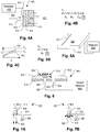
Fig. 4A shows a detector which uses a change in thermal properties of a detector surface to identify an accumulation of deposits on the surface. -
Fig. 4B shows a network model that may be used to model the response of the detector ofFig. 4A . -
Fig. 4C shows a plot of temperature samples for illustrating the operation of the detector ofFig. 4A . -
Fig. 5A shows another type of detector which uses a change in thermal properties of a detector surface to identify an accumulation of deposits on the surface. -
Fig. 5B shows a network model that may be used to model the response of the detector ofFig. 5A . -
Fig. 6 shows an optical detector which relies on scattering within a deposit film to detect the accumulation of a specified amount of material. -
Figs. 7A and 7B show a detector that detects scattering of light caused by accumulation of grease deposits on a detector. -
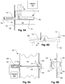
Figs. 8A and 8B show a passively cooled mechanical balance that can indicate the accumulation of grease on a detection surface by tilting. -
Figs. 9A and 9B shows other types of optical devices that indicates the accumulation of material by detecting a change in opacity. In particular,Fig. 9B shows an optical device that indicates the accumulation of material by detecting a change in opacity according to the invention. -
Fig. 10a shows a lever with a strain gauge that can indicate the accumulation of grease on a detection surface by deflection of the free end. -
Fig. 10b shows a cantilevered beam with a strain gauge that can indicate accumulation of grease on a detection surface by deflection of the free end. -
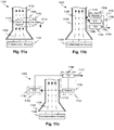
Fig. 11a shows a schematic of a generalized detector arrangement having a sensing element within the duct for determining the accumulation of fouling material in the duct. -
Fig. 11b shows a schematic of a generalized detector arrangement having a source and sensing element collocated external to the duct for determining an accumulation of fouling material in the duct. -
Fig. 11c shows a schematic of a generalized detector arrangement having a source on an opposite side of the duct from the sensing element for determining an accumulation of fouling material in the duct. - Referring now to
Fig. 1 , aduct 112 has anopening 116 through which is inserted a foulingdetector 125. The fouling detector has aplate 108 with adetection surface 109 protected by aremovable protector sheet 102. Anoscillator actuator 104, such as a piezoelectric crystal, causes theplate 108 to vibrate relative to a mountingsupport 106 attached to theduct 112. Agas stream 120, which contains suspended contaminant particles such as grease droplets, passes around thedetection surface 109 causing the suspended particles to impinge on the surface. Over time, a coating grows on thedetection surface 109. The coating increases the mass of theplate 108 such that the change in mass can be detected by a change in the resonance frequency of the plate. A sensor/drive 110 provides the driving signal to oscillate theplate 108 and to detect the resonant frequency. - Suitable detection devices are known in the art and are frequently used for deposition detection where high sensitivity to low deposition rates are required. One name for such devices is microscales. Examples of the applicable technologies are shown in the following patents :
U.S. Patent No. 6880402 for "Deposition monitoring system,"U.S. Patent No. 6124927 for "Method to protect chamber wall from etching by endpoint plasma clean,"U.S. Patent No. 5985032 for "Semiconductor manufacturing apparatus,"U.S. Patent No. 5897378 for "Method of monitoring deposit in chamber, method of plasma processing, method of dry-cleaning chamber, and semiconductor manufacturing apparatus,"U.S. Patent No. 5843232 for "Measuring deposit thickness in composite materials production,"U.S. Patent No. 5661233 for "Acoustic-wave sensor apparatus for analyzing a petroleum-based composition and sensing solidification of constituents therein,"U.S. Patent No. 5536359 for "Semiconductor device manufacturing apparatus and method with optical monitoring of state of processing chamber,"U.S. Patent No. 5112642 for "Measuring and controlling deposition on a piezoelectric monitor crystal,"U.S. Patent No. 5666394 for "Thickness measurement gauge,"U.S. Patent No. 6701787 for "Acoustic sensor for pipeline deposition characterization and monitoring of pipeline deposits,"U.S. Patent No. 5618992 for "Device and method for monitoring deposits in a pipe or vessel,"U.S. Patent No. 3023312 for "Radioactive pipe thickness measurement," andU.S. Patent No. 4429225 for "Infrared thickness measuring device." - The mass measurements required for detecting deposition films for the present purposes need not be as precise as required in some industries, such as those discussed in the above patents. In addition, substantial masses of material can provide suitable indications of deposit formation such that oscillating systems other than piezoelectric can be made using, for example, speaker coils and spring or other devices.
- The
protector sheet 102 may be, for example, a plastic sheet with an adhesive backing. By providing theprotector sheet 102, the fouling detector can be protected from being permanently coated with material accumulated from the gas stream. The foulingdetector 125 may be removed from the duct and theprotection sheet 102 replaced at a time after an indication has been generated by the sensor/driver 110. Preferably, the sensor/driver 110 is configured to run a test on a schedule, such as once per day or once every few days. Thus, the sensor/driver 110 can be provided with an alarm or it may be connected to a computer network to signal one or more remote terminals. -
Fig. 2 shows asupport 206 holdingmultiple fouling detectors surface detector portion Fig. 1 which measures the mass accumulated onplates Fig 2 illustrates that various mounting configurations for fouling detectors, as exemplified by foulingdetectors Fig. 2 illustrates that multiple fouling detectors may be combined when it is difficult to predict the configuration corresponding to the worst-case propensity for fouling. For example, foulingdetector 225A is partially "shaded" from the gas flow by foulingdetector 225B. This may induce eddies and stagnation regions which may cause worst-case deposition rates of fumes. The properties of turbulent flow are difficult to predict so that it may not be possible to determine in a real configuration which orientation would produce the worst-case result. Therefore, multiple detectors, each with a different orientation or configuration (for example "shaded") may be employed in a single device. Note that if foulingdetector 225A were used alone, a shading member could be used instead. - Other configuration parameters that may be varied include the distance the detector is located downstream of a shading member, the size of the shading member relative to the detector, and the orientation of the shading member (e.g., oblique). Other orientations are also possible such as angled non-rectilinearly and/or non-orthogonally.
- Referring to
Fig. 3A , preferably a detector of any given configuration has a deposition surface that models the worst-case characteristics of the duct other than just the orientation of the surface relative to the flow and the type of flow impinging thereon. For example, grease aerosols often deposit when the temperature of the particles reaches a condensation point. Ducting surfaces which are subject to fouling may be cooler than the flue stream and therefore may cause precipitation of material that is in a vapor phase while in the flue stream. To ensure that a detector collects material at least as effectively as the worst-case duct portion, a mechanism for cooling the deposition surface of the detector may be employed.Fig. 3A shows a foulingdetector 325 with anactive cooling mechanism 332, for example, a thermoelectric cooler. Asensor driver 110 anddetector portion 304 serve to measure the mass of accumulated material on adetection surface 302. A thermocouple or thermistor or othersuitable temperature sensor 330 may be provided as well as atemperature sensor T 336 for a space surrounding the ductwork. - A
controller 340 may, according to known feedback control, regulate a temperature of thedetection surface 302 so that its temperature corresponds closely to the worst-case ductwork surface portion, or slightly worse. For example, the temperature may be maintained at the temperature of the lowest air temperature to which the ductwork is exposed. Such temperature, mostly because of film resistance on either side of the duct surface and due to the resistance of insulation, if present, will be lower than any interior duct surface, at least during steady operation. Thus, it may be more representative to use an intermediate temperature between the duct interior (indicated by atemperature sensor 334 for the exhaust flow) and the ambient. - Preferably, the target temperature may be varied in time according to a model of the duct wall, the temperature of the exhaust flow, and/or the ambient temperature such that a real-time worst-case surface temperature is achieved. Such a real-time model may be implemented readily using a programmable processor and based on the indicated temperature inputs as well as the properties of a suitable duct wall model. For example, a one-dimensional thermal model of the duct wall may be derived using known equations for conductive, convective, and radiative heat transfer. For a given exhaust flow rate, measured exhaust flow temperature and ambient temperature may thus be used with the thermal model to derive the temperature of the surface of the duct. Changes in the measured temperatures can then be correlated to changes in the duct surface temperature. This calculated duct surface temperature may then be used as a target temperature for the cooling of the detection surface. The active cooling mechanism may be applied to any of the foregoing or yet-to-be-discussed fouling detector embodiments, or others.
-
Fig. 3B shows a passively cooled foulingdetector device 375. Asupport 354 supports a foulingdetector 350 in aduct interior 378. Achannel 352 conveysambient air 380 through it into theduct interior 352, which may be at a negative pressure relative to the ambient. The flow ofambient air 380 through thechannel 352, which is in contact with the foulingdetector 350, cools the foulingdetector 350 relative to theduct interior 378 temperature. Anadjustable damper blade 358 blocks theflow 356 through thechannel 352 to permit it to be regulated. A sensor/driver 310 controls the fouling detector and also may detect a temperature indicated by atemperature sensor 362 to permit an operator to adjust thedamper blade 358 based on the foulingdetector 350 temperature. Anair pump 366 may be used, with achannel extension 364, to force air into thechannel 352 if theduct interior 378 is under low negative or positive pressure. The passive cooling mechanism may be applied to any of the foregoing or yet-to-be-discussed fouling detector embodiments, or others. -
Fig. 4 shows a fouling detector that employs a thermal effect to determine the quantity of material deposited on adetection surface 412 of aplate 414. Adetector 400 monitors one or more temperatures by receiving corresponding signals from temperature sensors, forexample sensors plate 414 and the temperature on a heated side of theplate 414. A heater 410 (under control of the detector 400) heats theplate 412 as the temperature of the plate is monitored.Insulation 434 may be provided to reduce cooling of theplate 414 byambient air 422. As the temperature of theplate 414 rises, it tracks a time vs. temperature profile which corresponds to the insulation generated by a layer ofdeposit 419 on thedetection surface 412. Thedetector 400 may be configured to perform a test when the exhaust system is powered off, for example, to run the test according to a clock indication that off-operating hours are current or by detecting the status of the exhaust system. Preferably, the test is done when the temperature of the duct-side ambient gas (air) 420 is constant and there is no flow, so that the insulation provided by the layer ofdeposit 419 can be determined. -
Fig. 4B shows a simple one-dimensional network model for an infinite planar heat source whose power output is Q, which transfers heat to a node whose thermal capacitance is CW, and to an infinite sink at theduct air 420 temperature TD through a thermal resistance equal to that of the deposit RC and the film resistance RF on theduct air side 420. Referring also toFig. 4C , the RC, the quantity that is unknown, can be obtained by solving for the value of RC by fitting a plot (e.g. 430 corresponding to a high value of RC or 432 corresponding to a low value of RC) of the measured temperatures to the unsteady model (t indicating time). Equivalently, a steady state temperature (e.g., T1, T2) derived from an interpolation and used in the steady state model. Note that the model may take into account of the change in film coefficient with temperature due to thermal convection, so RF may be a function of temperature and time. For RF, the thickness of the deposited layer may be obtained from calibration data obtained using samples of deposited material. -
Fig. 5A shows a thermal fouling detector that corresponds to a simpler model than the one ofFig. 4A . It uses aheated wire 510 whose surface serves as the detection surface. The network model shown inFig. 5B is one-dimensional as in the previous embodiment (and there is a planar equivalent, which is an alternative embodiment). Here, the heat source may be a conducting film over an electrical and thermal insulator. A material with known variation of electrical resistance with temperature may be used, for example platinum. By measuring the voltage and current using adetector 500, the power dissipation rate and temperature may be obtained and measured over time from a starting time. As in the previous example, by fitting the temperature measurements to a suitable model of the system, the unknown value of RF may be derived and, from that, the thickness of the deposited layer. -
Fig. 6 shows anoptical fouling detector 640 which has aplate 618 with anillumination source 606 and alight sensor 604. A driver/detector 600 powers the illumination source, for example a light emitting diode with a lens, such that the illumination source directs light in a direction normal to adetection surface 616 when no material is deposited on the surface. When material accumulates on the surface as indicated at 612, light from theillumination source 606 is scattered in thematerial layer 612 and received by thelight sensor 604 as indicated byscattered beam 610. The greater the thickness of thematerial layer 612, the greater the scattering and the more light is received by thelight sensor 604. The driver/detector 600 may be configured to generate an indication of a specified degree of fouling when a threshold quantity of scattered light is detected thereby. Theillumination source 606 andlight sensor 604 may be complete devices that generate electrical signals throughlines 622 or they may be terminals of fiber optic channels also represented by 622. In the latter case, they may be located very close together. In addition,illumination source 606 andlight sensor 604 constitute one pair or there may be more than one of either or both. -
Figs. 7A and 7B show another type ofoptical fouling detector 822 in which alight source 802 directs light such that it does not fall on adetector 806 when the surface of a lens orwindow 804 is clean, as indicated by arrows (representing beams) 808. When the surface of the lens orwindow 804 becomes coated with deposited material, the light from thelight source 802 scatters as indicated byarrows 810. Some of the scattered light falls on thedetector 806. A driver/detector (not shown) functions as in the embodiment ofFig. 6 , generating an indication of a predefined degree of fouling after the quantity of light falling on thedetector 806 reaches a threshold. Asupport 814 can hold both thelight source 802 and thedetector 806 in position within the duct. - Note that the
detector 822 may be constructed of low cost materials and design such that it can be replaced each time the duct is cleaned. Thus, thedevice 822 generates a single indication and then is replaced. The driver/detector associated with it may be a permanent component. A disposable detector may be preferable to avoid the consequences of improper cleaning or change in performance characteristics of the fouling detector over time. All of the discussed embodiments may include single-use disposable components as discussed with regard toFigs. 7A and 7B . - Note that in both of the embodiments of
Fig. 6 and 7A, 7B , rather than triggering an indication of fouling based solely on total amount of light falling on the detector due to scattering, a light intensity curve can be obtained and memorized over time and compared with a representative profile for a detection surface that has become fouled. This may be preferable where the deposited material is not highly transmissive in its dried form, for example, if grease particles contained soot. In such a case, a representative profile may be one where the light intensity on the detector reaches a peak at a certain point in time and then decays due to further blocking by the deposited material. The fouling detection indication may be generated by detecting the peak or, in addition, after a drop in the light intensity that follows it of a certain amount. -
Figs 8A and 8B show a balance device in which abalance 750 has adetection surface 724 exposed tofumes 728 in aduct 726 and aportion 702 outside or shielded from thefumes 728 in theduct 726. The balance has a rectangular channel shape (but could be other shapes as well) such that awall 732 projects into a recess defining aflow path 728 between thewall 732 and thebalance 750. Air from outside the duct flows through theflow path 728 to cool thedetection surface 724 when fumes flow through theduct 726. Thebalance 750 pivots on aknife 714 which is located by anotch 716 defined by anopening 708 such that when thedetection surface 724 is clean, thedetection surface 724 is horizontal due to a balanced state. Since the pivot point coinciding with thenotch 716 is above the center of gravity, thebalance 750 will come to equilibrium at different angles depending on how much mass accumulates on thedetection surface 724. Thewall 732 prevents thebalance 750 from pivoting too far due to dynamic pressure from thefumes 728 during operation of the exhaust system such that thedetection surface 724 always remains substantially level as indicated by theoutline 704 inFig. 8B . When a certain amount of material is deposited on foulingsurface 724, thebalance 750 is tipped until contact between it and acontact 710 is made, completing a circuit and triggering an indication of a fouled condition. As in previous embodiments, the test may be performed only when the exhaust system is not operating according to a clock or a detector of the exhaust system state. Thedetector 700 may be configured such that a constant closed circuit for a minimum period of time must be maintained in order to generate an indication of a fouled condition. Thewall 732 and/orknife 714 may include one or more electrical insulators depending on how the electrical circuit is defined by the structure. As in previous embodiments, the balance may be a disposable component which is replaced after a fouled state is indicated. -
Fig. 9A shows another optical type of fouling detector in which opacity caused by a deposited film is detected and a degree of occultation used as a basis for indicating a fouled condition. Alight source 918 shines a light through awindow 914 toward adetector 901 located in awell 902.Air 905 is drawn through the well 902 to keep material from fouling thedetector 901. Light is projected as indicated byarrows 912 toward thedetector 901 generating a signal indicative of the amount of light which is received by adetector control 908, which generates a fouled condition indication when the amount of light received falls below a threshold level. Thewindow 914 may be cooled by a flow of air as indicated byarrow 917 by providing appropriate openings in thehousing 919. Thedetector 901 and thelight source 918 are located on opposite sides of aduct 900 so that fumes are deposited on thewindow 914.Fig. 9B shows foulingdetector 952 according to the invention, which does not require that portions of the detector be located on opposite sides of the duct. Alight source 960 directs light toward amirror 958 which is reflected back to adetector 962. Themirror 958 is supported by alow profile arm 958 so that exhaust can flow around it easily causing material in the exhaust to be deposited on themirror 958. The foulingdetector 952 can be placed in a single access opening of aduct wall 966. Anactive cooling mechanism 956 may be provided. The foulingdetector 952 can be configured such that the mirror is located at nearly any desirable angle or positioning thelight source 960 and the detector. The angle of the mirror can be non-critical if replaced by a diffuse reflector material (typically a bed of spherical particles that return light to the source irrespective of the orientation of the bed). -
Fig. 10a shows an example of afouling detector 1000 employing alever 1004 with asensor 1008 that can indicate the accumulation of grease on adetection surface 1018 by deflection of thefree end 1020. Thelever 1004 is rotatably fixed atpivot point 1012. Aspring 1010 is provided aboutpivot point 1012 and adjusted to hold the lever in a parallel orientation when no grease has accumulated on the lever.Support 1014 holds thelever 1004 viapivot point 1012 andspring 1010 at a fixed position with respect toduct wall 1002. As grease inflow 1006 within the duct accumulates on thedetection surface 1018, the increased mass of thelever 1004 causes the lever to rotate aboutpivot 1012 in a counter-clockwise manner. Asensor 1008 may be provided in contact with thelever 1004 at a position outside ofduct wall 1002. For example, thesensor 1008 may be a strain gauge. In another example,sensor 1008 may be a force sensor. In yet another example,sensor 1008 may be a displacement sensor, such as a capacitive sensor. Thesensor 1008 generates a signal indicative of movement of the lever due to the additional mass of the accumulated grease on thedetection surface 1018. Thecontroller 1016 may then use the signal to determine a fouling condition of the duct, such as the amount of grease accumulated on the detection surface. -
Fig. 10b shows another example of afouling detector 1050 employing acantilevered beam 1052 with astrain gauge 1054 that can indicate the accumulation of grease on adetection surface 1060 by deflection of thefree end 1062.Support 1056 rigidly fixes thecantilever 1052 adjacent to theduct wall 1002. As grease inflow 1006 within the duct accumulates on thedetection surface 1060, the increased mass of thecantilever 1052 causes the cantilever to bend. Astrain gauge 1054 is provided on a top (or bottom) surface of the cantilever to determine the amount of bending. Calibration of the strain gauge measurement would be necessary to compensate for the natural bending of the cantilever due to its own weight. Thestrain gauge 1054 thus generates a signal indicative of the degree of bending of the cantilever due to the additional mass of the accumulated grease on thedetection surface 1060. Acontroller 1058 may then use the signal to determine a fouling condition of the duct, such as the amount of grease accumulated on the detection surface. -
Fig. 11a shows a generalized schematic 1100 of a foulingdetector arrangement 1108. Anair conveyance 1102, such as an exhaust duct, is used to carry anexhaust stream 1106 from a source ofcontamination 1104, such as a cooking appliance.Exhaust stream 1106 may carry aerosols, such as grease aerosols, which may be deposited on interior surfaces of theair conveyance 1102. A foulingdetector arrangement 1108 may be provided to detect the deposition of aerosols or other pollutants. In particular, foulingdetector arrangement 1108 may include asensing element 1110 and acontroller 1112. -
Sensing element 1110 may be disposed within theexhaust stream 1106 inair conveyance 1102 to allow aerosols or pollutants to interact therewith. For example,sensing element 1110 may have a detection surface exposed to theexhaust stream 1106 which accumulates aerosols and/or pollutants resulting in a change in a property of the detection surface. -
Controller 1112 may be functionally connected to thesensing element 1110. Thecontroller 1112 may interrogate thesensing element 1110 to obtain a measurement indicative of the level of accumulated aerosol and/or pollutants within the duct. For example,controller 1112 may interrogatesensing element 1110 to determine a change in mass of the detection surface.Controller 1112 may also be configured to provide asubsequent output 1114 based on the interrogation. For example,controller 1112 may activate an alarm system if the amount of accumulated contamination exceeds a predetermined threshold.Controller 1112 may also display a level of accumulated contamination to a user. Such display may take the form of a number or a color-coded display indicating a relative safety level (e.g., green may indicate safe to operate, yellow may indicate clean air conveyance soon, and red may indicate unsafe to operate).Controller 1112 may also provide anoutput 1114 to other systems, such as an automatic air conveyance cleaning system to provide for cleaning of theair conveyance 1102 when accumulated contamination levels reach a predetermined threshold. -
Fig. 11b shows a generalized schematic 1130 of a foulingdetector arrangement 1132. Anair conveyance 1102, such as an exhaust duct, is used to carry anexhaust stream 1106 from a source ofcontamination 1104, such as a cooking appliance. In contrast to the schematic ofFig. 11a , the foulingdetector arrangement 1132 ofFig. 11b may be provided external to theair conveyance 1102 to detect deposition of aerosol or other pollutants on the air conveyance walls. In particular, foulingdetector arrangement 1132 may include asource 1134, asensing element 1138, and acontroller 1142. Thus, the foulingdetector arrangement 1132 is isolated from the contaminants in theexhaust stream 1106. Thesource 1134 interrogates the surface of theair conveyance 1102 by generating asignal 1136 and thesensing element 1138 measures theresult 1140 of the interrogation to determine the amount of contaminant accumulated on the surface of theair conveyance 1102. For example,source 1134 may be a source of acoustic or electromagnetic radiation. The radiation is modified in some form and measured by thesensing element 1138. Note that both thesource 1134 andsensing element 1138 may be located on the same side of theair conveyance 1102 and preferably oriented such that radiation emanating from thesource 1134 and modified by theair conveyance 1102 can be received bysensing element 1138.Controller 1142 may be functionally connected to thesensing element 1138 and may use the measurement of the sensing element to determine a level of accumulated contaminants within theair conveyance 1106. Similar tocontroller 1112 inFig. 11a ,controller 1142 may also be configured to provide asubsequent output 1144 based on the determination of the level of accumulated contaminants. - In a particular example, the
source 1134 may be an acoustic transmitter and thesensing element 1138 may be an acoustic sensor. The acoustic transmitter may generate an acoustic signal. The acoustic signal interacts with the air conveyance and is reflected. A first reflection occurs at the external surface of the air conveyance. A second reflection occurs at the internal surface of the air conveyance. A third reflection occurs at the surface of the contamination layer accumulated on the internal surface of the air conveyance. The reflected signals are received by the acoustic sensor. The controller may then use the received reflected signals to calculate acoustic impedance, as discussed, for example, inU.S. Patent No. 6701787 . The acoustic impedance may then be correlated to the thickness of the deposited layer. - In yet another example, the
source 1134 may be a radioactive source and thesensing element 1138 may be a slow neutron detector. For example, neutrons from a radioactive source may be allowed to interact with a wall of the duct having an accumulated contamination on an interior surface thereof. Fast moving neutrons penetrate the pipe wall without significant interaction and may be elastically scattered by hydrogen or carbon atoms in the contamination. The scattering slows the neutrons, causing some neutrons to be reflected and/or diffuse back towards the radioactive source. A detector, such as a BF3 slow neutron detector, may be placed in proximity to the radioactive source in a position to measure the reflected and/or diffused slow neutrons. The detected slows neutrons thus provide an indication of the thickness of the accumulated contamination. - In yet another example, the
source 1134 may be an electromagnetic radiation source, such as an infrared (IR) transmitter, and thesensing element 1138 may be an electromagnetic radiation sensor. The IR transmitter may generate an IR signal. The IR signal interacts with the air conveyance and is reflected and/or absorbed by the materials it encounters. A first reflection occurs at the external surface of the air conveyance. A second reflection occurs at the internal surface of the air conveyance. A third reflection occurs at the surface of the contamination layer accumulated on the internal surface of the air conveyance. The reflected signals are received by the electromagnetic radiation sensor. The controller may then use the received reflected signals to calculate the thickness of the deposited layer. -
Fig. 11c shows a generalized schematic 1160 of a foulingdetector arrangement 1162. Anair conveyance 1102, such as an exhaust duct, is used to carry anexhaust stream 1106 from a source ofcontamination 1104, such as a cooking appliance. Foulingdetector arrangement 1162 may include asource 1166, asensing element 1164, and acontroller 1168 external to theair conveyance 1102. Thus, the foulingdetector arrangement 1162 is isolated from the contaminants in theexhaust stream 1106. In contrast to the schematic ofFig. 11b , the foulingdetector arrangement 1162 ofFig. 11c may be provided withsource 1166 located at an opposite side of theair conveyance 1102 with respect to thesensing element 1164. - The
source 1166 interrogates the surfaces of theair conveyance 1102 by generating asignal 1170 and thesensing element 1164 measures thesignal 1170, as modified by theair conveyance 1102, to determine the amount of contaminant accumulated on the surface of theair conveyance 1102. For example,source 1166 may be a source of acoustic or electromagnetic radiation. The radiation is modified in some form and measured by thesensing element 1164. Note that both thesource 1166 andsensing element 1164 are located opposite each other and preferably oriented such that radiation emanating from thesource 1166 and modified by theair conveyance 1102 can be received bysensing element 1164.Controller 1168 may be functionally connected to thesensing element 1164 and may use the measurement of the sensing element to determine a level of accumulated contaminants within theair conveyance 1102. Similar tocontroller 1112 inFig. 11a ,controller 1168 may also be configured to provide asubsequent output 1172 based on the determination of the level of accumulated contaminants. - In a particular example, the
source 1166 may be an acoustic transmitter and thesensing element 1164 may be an acoustic sensor. The acoustic transmitter may generate an acoustic signal. The acoustic signal interacts with the air conveyance and is reflected. The transmitted signal through theair conveyance 1102 is received by the acoustic sensor. The controller may then use the received transmitted signal to calculate the thickness of the deposited layer. - In yet another example, the
source 1166 may be an electromagnetic radiation source, such as an infrared (IR) transmitter, and thesensing element 1164 may be an electromagnetic radiation sensor. The IR transmitter may generate an IR signal. The IR signal interacts with the air conveyance and is selectively absorbed by the materials encountered in traversing the air conveyance. The attenuated transmitted signal is received by the electromagnetic radiation sensor. The controller may then use the received attenuated signals to calculate the thickness of the deposited layer. - Any of the foregoing examples may employ an active or passive cooling mechanism as described with reference to certain examples. Any of the above examples may take samples during periods of non-operation of the exhaust system based on indications of a clock, an exhaust system state detection (fan power signal, for example), and/or manually. Any of the above examples may sample the detected property at intervals and store the values to obtain a trend and use the trend pattern to identify the fouled condition, rather than an instantaneous state. The trend may be derived by studying the properties of the indicator signal compared to the fouling status of the detection surface and providing an appropriate reference to the control. Fouling by different kinds of uses of the exhaust system, which may not be known in advance, may produce different types of results, each associated with a corresponding response by the fouling detector so preferably these variations are taken into account to improve upon the accuracy of the fouled condition indication.
Claims (4)
- A fouling detector for detecting grease fouling deposited on an internal surface of an exhaust duct that removes cooking fumes from a kitchen, comprising:a member for being placed with a surface in an exhaust stream,the member surface having or being a mirror (958) or a diffuse reflector;a light source (960) configured to direct light toward the member surface; anda detector (962) configured to receive light reflected from the member surface,characterized in that the member is coupled to the light source and the detector by a low profile arm (959) such that exhaust can flow around the member easily causing material in the exhaust to be deposited on the member surface,wherein the fouling detector is configured to be placed in a single access opening of a duct wall (966).
- The fouling detector of claim 1, characterized by a signal generation device configured to indicate a fouled condition of the surface due to a change in a property of the surface indicative of fouling wherein the property is reflectivity.
- The fouling detector of any one of the preceding claims, further comprising an active cooling mechanism (956).
- The fouling detector of any one of the preceding claims, further comprising a controller and wherein the controller is configured to be usable to take a sample measurement when an exhaust system is not operating.
Priority Applications (1)
| Application Number | Priority Date | Filing Date | Title |
|---|---|---|---|
| PL13177388T PL2669651T3 (en) | 2007-06-13 | 2008-06-13 | Fouling detector for detecting grease fouling in a duct |
Applications Claiming Priority (3)
| Application Number | Priority Date | Filing Date | Title |
|---|---|---|---|
| US94362607P | 2007-06-13 | 2007-06-13 | |
| EP08771092.7A EP2165172B1 (en) | 2007-06-13 | 2008-06-13 | Duct grease deposit detection devices, systems, and methods |
| PCT/US2008/067000 WO2008157418A1 (en) | 2007-06-13 | 2008-06-13 | Duct grease deposit detection devices, systems, and methods |
Related Parent Applications (3)
| Application Number | Title | Priority Date | Filing Date |
|---|---|---|---|
| EP08771092.7 Division | 2008-06-13 | ||
| EP08771092.7A Division-Into EP2165172B1 (en) | 2007-06-13 | 2008-06-13 | Duct grease deposit detection devices, systems, and methods |
| EP08771092.7A Division EP2165172B1 (en) | 2007-06-13 | 2008-06-13 | Duct grease deposit detection devices, systems, and methods |
Publications (3)
| Publication Number | Publication Date |
|---|---|
| EP2669651A2 EP2669651A2 (en) | 2013-12-04 |
| EP2669651A3 EP2669651A3 (en) | 2013-12-11 |
| EP2669651B1 true EP2669651B1 (en) | 2020-12-09 |
Family
ID=40156640
Family Applications (2)
| Application Number | Title | Priority Date | Filing Date |
|---|---|---|---|
| EP13177388.9A Active EP2669651B1 (en) | 2007-06-13 | 2008-06-13 | Fouling detector for detecting grease fouling in a duct |
| EP08771092.7A Active EP2165172B1 (en) | 2007-06-13 | 2008-06-13 | Duct grease deposit detection devices, systems, and methods |
Family Applications After (1)
| Application Number | Title | Priority Date | Filing Date |
|---|---|---|---|
| EP08771092.7A Active EP2165172B1 (en) | 2007-06-13 | 2008-06-13 | Duct grease deposit detection devices, systems, and methods |
Country Status (11)
| Country | Link |
|---|---|
| US (3) | US8487776B2 (en) |
| EP (2) | EP2669651B1 (en) |
| JP (3) | JP2010530964A (en) |
| AU (1) | AU2008265939C1 (en) |
| BR (1) | BRPI0812733B1 (en) |
| CA (1) | CA2690615C (en) |
| DK (2) | DK2165172T3 (en) |
| MX (1) | MX2009013598A (en) |
| PL (2) | PL2165172T3 (en) |
| WO (1) | WO2008157418A1 (en) |
| ZA (1) | ZA201000103B (en) |
Families Citing this family (55)
| Publication number | Priority date | Publication date | Assignee | Title |
|---|---|---|---|---|
| CA2571268C (en) | 2004-06-22 | 2010-05-18 | Oy Halton Group Ltd. | Set and forget exhaust controller |
| WO2006012628A2 (en) | 2004-07-23 | 2006-02-02 | Halton Company | Improvements for control of exhaust systems |
| CA2793796C (en) | 2006-04-18 | 2016-07-05 | Oy Halton Group, Ltd. | Modular wall unit with mini exhaust hood |
| US20080274683A1 (en) | 2007-05-04 | 2008-11-06 | Current Energy Controls, Lp | Autonomous Ventilation System |
| US20090061752A1 (en) | 2007-08-28 | 2009-03-05 | Current Energy Controls, Lp | Autonomous Ventilation System |
| GB0724779D0 (en) * | 2007-12-20 | 2008-01-30 | Vanguard Sensor Technologies L | Monitoring system |
| BRPI0910709B1 (en) | 2008-04-18 | 2020-10-27 | Oy Halton Group Ltd | exhaust device |
| DE102008048090B3 (en) * | 2008-09-19 | 2010-02-04 | Kornack-Cielewicz, Katja | Duct system for kitchen exhaust |
| MX2011005770A (en) | 2008-12-03 | 2011-08-15 | Halton Group Ltd Oy | Exhaust flow control system and method. |
| US20120055275A1 (en) * | 2010-09-02 | 2012-03-08 | Streivor Air Systems, Inc. | System and Method for Smart Operation of an Exhaust Hood Using a Protected Monitoring Device |
| US9414024B2 (en) * | 2010-10-12 | 2016-08-09 | Enertechnix, Inc. | Terahertz imaging |
| MX2013006280A (en) | 2010-12-05 | 2013-08-01 | Halton Group Ltd Oy | Ultraviolet monitoring systems, methods, and devices. |
| GB2493354A (en) * | 2011-07-29 | 2013-02-06 | Prevent Systems Ltd | Detecting deposits build-up in a ventilation duct |
| BR112014015326B1 (en) * | 2011-12-22 | 2020-12-15 | Solenis Technologies Cayman, L.P | DEVICE AND METHOD FOR DETECTION OF DEPOSITS |
| DE102012213692A1 (en) * | 2012-08-02 | 2014-02-06 | BSH Bosch und Siemens Hausgeräte GmbH | Vapor extraction device and method for controlling a fan motor of a fan and for air cleaning effect determination |
| FI124057B (en) | 2012-12-05 | 2014-02-28 | Metso Power Oy | Arrangements in a thermal process and method for measuring the thickness of a soil layer |
| US9151722B2 (en) * | 2014-01-15 | 2015-10-06 | King Abdulaziz University | Systems for determining and imaging wax deposition and simultaneous corrosion and wax deposit determination in pipelines |
| WO2015127547A1 (en) * | 2014-02-27 | 2015-09-03 | Walter Surface Technologies Inc. | Industrial cleanliness measurement methodology |
| KR101679231B1 (en) * | 2014-07-02 | 2016-12-06 | 주식회사 지오시스 | Fire extinguishing system for commercial kitchen |
| WO2016089688A1 (en) | 2014-12-01 | 2016-06-09 | 3M Innovative Properties Company | Systems and methods for predicting hvac filter change |
| JP6581855B2 (en) * | 2015-09-08 | 2019-09-25 | 三菱日立パワーシステムズ株式会社 | Foreign matter inspection method and foreign matter inspection jig |
| CN105091059B (en) * | 2015-09-12 | 2018-01-26 | 徐建立 | Cleaning device for cooking fume exhauster and its control method |
| CN106051857A (en) * | 2016-06-15 | 2016-10-26 | 广东美的厨房电器制造有限公司 | Range hood and cleaning method thereof |
| CN106111593A (en) * | 2016-07-14 | 2016-11-16 | 广东美的厨房电器制造有限公司 | Control the method and apparatus carrying out Fouling Cleaning |
| KR101985531B1 (en) * | 2016-08-01 | 2019-06-03 | 엘지전자 주식회사 | Filter assembly, air cleaning apparatus including the same and a method for controlling the air cleaning apparatus |
| WO2018156149A1 (en) * | 2017-02-24 | 2018-08-30 | Ecolab Usa Inc. | Thermoelectric deposit monitor |
| JP6842955B2 (en) * | 2017-03-13 | 2021-03-17 | 三菱電機株式会社 | Cooker |
| WO2018175495A1 (en) * | 2017-03-20 | 2018-09-27 | Oy Halton Group Ltd. | Fire safety devices methods and systems |
| US20180304316A1 (en) * | 2017-04-21 | 2018-10-25 | Sebastien Khandjian | Systems and methods to clean ducts |
| CN107121302B (en) * | 2017-06-12 | 2023-09-15 | 武汉黎赛科技有限责任公司 | Comprehensive detection device and method for wheel rail lubrication |
| CN107366938B (en) * | 2017-07-19 | 2019-01-18 | 珠海格力电器股份有限公司 | A kind of air cleaning facility and its control method and device |
| CN109916855B (en) * | 2017-12-13 | 2021-08-20 | 宁波方太厨具有限公司 | Data processing method of oil smoke sensor |
| CN108119985A (en) * | 2017-12-21 | 2018-06-05 | 珠海格力电器股份有限公司 | Method for cleaning air duct, device and air-conditioning |
| KR102498059B1 (en) * | 2017-12-28 | 2023-02-10 | (주)보부하이테크 | Device module and method for measuring semiconductor residual production in exhaust pipe |
| JP7155525B2 (en) * | 2018-01-15 | 2022-10-19 | 日新電機株式会社 | Dust accumulation detector |
| CN111121115A (en) * | 2018-10-30 | 2020-05-08 | 宁波方太厨具有限公司 | Volute oil accumulation detection reminding method |
| US11953458B2 (en) * | 2019-03-14 | 2024-04-09 | Ecolab Usa Inc. | Systems and methods utilizing sensor surface functionalization |
| US11114286B2 (en) * | 2019-04-08 | 2021-09-07 | Applied Materials, Inc. | In-situ optical chamber surface and process sensor |
| CN110030722B (en) * | 2019-04-23 | 2020-09-18 | 江苏华舜环境工程有限公司 | Energy-concerving and environment-protective automatically cleaning chimney |
| CN110131768A (en) * | 2019-05-22 | 2019-08-16 | 张玉波 | A kind of energy-saving and environment-friendly spiral automatically cleaning chimney |
| SE544067C2 (en) | 2019-06-26 | 2021-11-30 | Bioteria Tech Ab | Methods, system and device for controlling biological treatment processes and systems |
| US11320363B2 (en) | 2019-09-03 | 2022-05-03 | Halliburton Energy Services, Inc. | Treatment of pipeline deposits |
| CN110617526B (en) * | 2019-09-25 | 2021-03-19 | 佛山市顺德区美的洗涤电器制造有限公司 | Kitchen device |
| CN110617535B (en) * | 2019-09-25 | 2021-03-19 | 佛山市顺德区美的洗涤电器制造有限公司 | Kitchen device |
| CN110988972B (en) * | 2019-10-12 | 2022-10-21 | 中国辐射防护研究院 | High-precision three-dimensional portable surface pollution instrument calibrating device |
| US11499869B2 (en) * | 2019-11-13 | 2022-11-15 | Applied Materials, Inc. | Optical wall and process sensor with plasma facing sensor |
| JP2022023372A (en) * | 2020-07-27 | 2022-02-08 | 株式会社アガタ | Closing space monitoring device |
| CN112147030A (en) * | 2020-09-26 | 2020-12-29 | 国网山东省电力公司电力科学研究院 | Device and method for detecting dirt deposition amount of external insulation part |
| CN114017397A (en) * | 2021-11-29 | 2022-02-08 | 广东万和电气有限公司 | Cleaning method of fan assembly and range hood |
| CN114234251B (en) * | 2021-12-17 | 2023-07-25 | 杭州老板电器股份有限公司 | Flue state identification method and device of smoke machine |
| CN114543687A (en) * | 2022-01-07 | 2022-05-27 | 山东山消智慧安全科技有限公司 | System and method for monitoring thickness of flue oil dirt |
| CN115032123A (en) * | 2022-03-21 | 2022-09-09 | 哈尔滨工程大学 | Experimental device for studying aerosol deposition characteristics in pipelines under different thermal conditions |
| CN115541438B (en) * | 2022-12-02 | 2023-05-02 | 山东理工职业学院 | Portable multi-environment atmospheric environmental pollution detector and use method thereof |
| CN116592774B (en) * | 2023-07-18 | 2023-09-19 | 成都洋湃科技有限公司 | Pipe wall dirt detection method and device, storage medium and electronic equipment |
| CN116753873B (en) * | 2023-08-14 | 2023-10-27 | 成都顿威新型金属材料有限公司 | Device and method for detecting thickness of composite lithium belt |
Citations (3)
| Publication number | Priority date | Publication date | Assignee | Title |
|---|---|---|---|---|
| JPS60140037A (en) * | 1983-12-27 | 1985-07-24 | Matsushita Electric Ind Co Ltd | Smoke exhauster |
| JPH0979979A (en) * | 1995-09-13 | 1997-03-28 | Toyota Motor Corp | Smoke concentration detector for internal combustion engine |
| JPH10170438A (en) * | 1996-12-13 | 1998-06-26 | Nippon Winton Kk | Dust detecting device in air-conditioning duct, and method for discriminating contamination degree |
Family Cites Families (52)
| Publication number | Priority date | Publication date | Assignee | Title |
|---|---|---|---|---|
| GB815347A (en) | 1957-02-22 | 1959-06-24 | Plinio Piacentini | Improvements in traffic signals |
| GB815366A (en) | 1955-09-14 | 1959-06-24 | British Thomson Houston Co Ltd | Improvements in and relating to electrical control systems |
| GB724779A (en) | 1953-01-14 | 1955-02-23 | John Tomkins | An apparatus for sealing envelopes |
| US3023312A (en) * | 1957-10-03 | 1962-02-27 | Tuboscope Company | Radioactive pipe thickness measurement |
| US3810009A (en) * | 1971-10-06 | 1974-05-07 | Universal Oil Prod Co | Apparatus for measuring material fouling of a test specimen |
| US3890827A (en) * | 1973-08-23 | 1975-06-24 | Cylpik Inc | Method and apparatus for monitoring grease buildup within an exhaust system |
| JPS5373168A (en) * | 1976-12-13 | 1978-06-29 | Hokushin Gohan Kk | Measuring method and apparatus for weight of powdered articles in wind sending process |
| GB2077426B (en) | 1980-05-30 | 1983-12-14 | Fuji Electric Co Ltd | Apparatus for measuring film thickness |
| DE3030499C2 (en) * | 1980-08-12 | 1982-05-27 | Siemens AG, 1000 Berlin und 8000 München | Arrangement for the detection of particles in a gas flow |
| US4524835A (en) | 1981-01-30 | 1985-06-25 | Mingrone Frank V | Fire suppression systems |
| JPS6033143U (en) | 1983-08-11 | 1985-03-06 | 株式会社長谷工コーポレーション | ventilation fan |
| JPS6325359U (en) * | 1986-08-04 | 1988-02-19 | ||
| US4912332A (en) * | 1988-06-03 | 1990-03-27 | Research And Development Institute, Inc. At Montana State University | Non-destructive methods for detecting organic deposits and removing them |
| IE70325B1 (en) * | 1989-05-15 | 1996-11-13 | Akzo Nv | Apparatus for detection of microorganisms |
| US5112642A (en) * | 1990-03-30 | 1992-05-12 | Leybold Inficon, Inc. | Measuring and controlling deposition on a piezoelectric monitor crystal |
| US5096502A (en) * | 1990-12-03 | 1992-03-17 | The Babcock & Wilcox Company | Advanced water lance control system based on peak furnace wall emissivity |
| JP3399040B2 (en) | 1993-09-20 | 2003-04-21 | 株式会社日立製作所 | Semiconductor manufacturing apparatus and semiconductor manufacturing method |
| JPH07134089A (en) * | 1993-11-09 | 1995-05-23 | Toyota Motor Corp | Paint mist detection method |
| ES2124011T3 (en) * | 1994-08-23 | 1999-01-16 | Foster Wheeler Energia Oy | OPERATING PROCEDURE OF A FLUIDIZED BED REACTOR SYSTEM AND ASSOCIATED SYSTEM. |
| GB9419886D0 (en) | 1994-10-03 | 1994-11-16 | Boc Group Plc | 0 161194 GB 9419886A 031094 GB 9419886A 031094Device for monitoring deposits in a pipe or vessel |
| DE19510304C1 (en) | 1995-03-22 | 1996-02-01 | Leuze Electronic Gmbh & Co | Light barrier grid |
| US5985032A (en) * | 1995-05-17 | 1999-11-16 | Matsushita Electric Industrial Co., Ltd. | Semiconductor manufacturing apparatus |
| US5843232A (en) * | 1995-11-02 | 1998-12-01 | General Electric Company | Measuring deposit thickness in composite materials production |
| US5661233A (en) * | 1996-03-26 | 1997-08-26 | Sandia Corporation | Acoustic-wave sensor apparatus for analyzing a petroleum-based composition and sensing solidification of constituents therein |
| US5666394A (en) * | 1996-04-23 | 1997-09-09 | Northrop Grumman Corporation | Thickness measurement gauge |
| US6025916A (en) * | 1997-02-27 | 2000-02-15 | Wisconsin Alumni Research Foundation | Wall deposition thickness sensor for plasma processing chamber |
| FR2760531B1 (en) * | 1997-03-07 | 1999-04-16 | Inst Francais Du Petrole | DEVICE FOR DETECTING FOULING AND LOCALLY HEATING AN INSULATING MEDIUM |
| JP3525033B2 (en) * | 1997-07-07 | 2004-05-10 | シャープ株式会社 | Air conditioner with automatic ventilation function |
| US6170480B1 (en) * | 1999-01-22 | 2001-01-09 | Melink Corporation | Commercial kitchen exhaust system |
| US6124927A (en) * | 1999-05-19 | 2000-09-26 | Chartered Semiconductor Manufacturing Ltd. | Method to protect chamber wall from etching by endpoint plasma clean |
| GB9925373D0 (en) * | 1999-10-27 | 1999-12-29 | Schlumberger Ltd | Downhole instrumentation and cleaning system |
| US6536649B1 (en) * | 2000-07-28 | 2003-03-25 | Advanced Micro Devices, Inc. | Method of preventing residue contamination of semiconductor devices during furnace processing |
| JP2002286636A (en) * | 2001-01-19 | 2002-10-03 | Advantest Corp | Chemical substance detecting method and device |
| US6513385B1 (en) * | 2001-05-08 | 2003-02-04 | Halliburton Energy Services, Inc. | Acoustic sensor for pipeline deposition characterization and monitoring |
| TW552188B (en) * | 2001-11-16 | 2003-09-11 | Towa Corp | Apparatus and method for evaluating degree of adhesion of adherents to mold surface, apparatus and method for surface treatment of mold surface and method and apparatus for cleaning mold used for molding resin |
| JP3735293B2 (en) * | 2001-11-21 | 2006-01-18 | 三菱重工業株式会社 | Sea salt particle monitoring method, sea salt particle cleaning monitoring method, and sea salt particle cleaning monitoring device |
| GB0128704D0 (en) * | 2001-11-30 | 2002-01-23 | Univ Manchester | Remote pipeline inspection |
| EP1318211B1 (en) | 2001-12-07 | 2008-08-27 | Infineon Technologies SC300 GmbH & Co. KG | Arrangement for monitoring a thickness of a layer depositing on a sidewall of a processing chamber |
| US7354429B2 (en) * | 2003-05-27 | 2008-04-08 | Integrated Sensing Systems, Inc. | Device and method for detecting and treating chemical and biological agents |
| US20040231400A1 (en) * | 2003-05-19 | 2004-11-25 | Bradenbaugh Kenneth A. | Method and apparatus for detecting accumulation of particulate matter from a flowing air stream |
| DE10351254A1 (en) * | 2003-11-03 | 2005-06-02 | Adc Automotive Distance Control Systems Gmbh | Apparatus for detecting soiling on a translucent cover in front of an optical unit |
| US7178410B2 (en) * | 2004-03-22 | 2007-02-20 | Cleanalert, Llc | Clogging detector for air filter |
| JP4025308B2 (en) * | 2004-03-31 | 2007-12-19 | 株式会社山武 | Mirror surface cooling type sensor |
| DE102004029524B4 (en) * | 2004-06-18 | 2007-12-06 | Robert Bosch Gmbh | Method and device for the defined regeneration of sooty surfaces |
| US7866211B2 (en) * | 2004-07-16 | 2011-01-11 | Rosemount Inc. | Fouling and corrosion detector for process control industries |
| US7741108B2 (en) * | 2005-01-14 | 2010-06-22 | Optech Ventures, Llc | Bacteria sensor and method |
| DE102005041004A1 (en) * | 2005-08-29 | 2007-03-01 | Cmv Systems Gmbh & Co.Kg | Monitoring procedure for formation of deposits in combustion chamber, involves comparing predetermined surface temperature and thickness of combustion chamber walls with wall surface temperature and thickness measured using infrared cameras |
| EP1987319B1 (en) | 2006-02-13 | 2018-04-11 | Solenis Technologies Cayman, L.P. | Measuring system for the acquisition of the layer thickness of a deposit |
| US20070189356A1 (en) * | 2006-02-13 | 2007-08-16 | Jonathan Pettit | Exhaust buildup monitoring in semiconductor processing |
| US7465332B2 (en) * | 2006-04-21 | 2008-12-16 | Gemchar, Llc | Disposable grease filter for air filtration system and method of manufacturing same |
| US20080100826A1 (en) * | 2006-10-26 | 2008-05-01 | Richard Sharpe | Devices For Monitoring Particulate Accumulation On A Filter And Related Methods |
| GB0724779D0 (en) | 2007-12-20 | 2008-01-30 | Vanguard Sensor Technologies L | Monitoring system |
-
2008
- 2008-06-13 EP EP13177388.9A patent/EP2669651B1/en active Active
- 2008-06-13 WO PCT/US2008/067000 patent/WO2008157418A1/en active Application Filing
- 2008-06-13 PL PL08771092T patent/PL2165172T3/en unknown
- 2008-06-13 JP JP2010512404A patent/JP2010530964A/en active Pending
- 2008-06-13 AU AU2008265939A patent/AU2008265939C1/en active Active
- 2008-06-13 DK DK08771092.7T patent/DK2165172T3/en active
- 2008-06-13 US US12/664,369 patent/US8487776B2/en active Active
- 2008-06-13 EP EP08771092.7A patent/EP2165172B1/en active Active
- 2008-06-13 BR BRPI0812733A patent/BRPI0812733B1/en active IP Right Grant
- 2008-06-13 CA CA2690615A patent/CA2690615C/en active Active
- 2008-06-13 DK DK13177388.9T patent/DK2669651T3/en active
- 2008-06-13 PL PL13177388T patent/PL2669651T3/en unknown
- 2008-06-13 MX MX2009013598A patent/MX2009013598A/en active IP Right Grant
-
2010
- 2010-01-06 ZA ZA2010/00103A patent/ZA201000103B/en unknown
-
2012
- 2012-11-12 JP JP2012248262A patent/JP5868307B2/en active Active
-
2013
- 2013-06-09 US US13/913,484 patent/US20130271748A1/en not_active Abandoned
-
2014
- 2014-07-07 US US14/324,981 patent/US20140318284A1/en not_active Abandoned
- 2014-09-30 JP JP2014201251A patent/JP2014240750A/en active Pending
Patent Citations (3)
| Publication number | Priority date | Publication date | Assignee | Title |
|---|---|---|---|---|
| JPS60140037A (en) * | 1983-12-27 | 1985-07-24 | Matsushita Electric Ind Co Ltd | Smoke exhauster |
| JPH0979979A (en) * | 1995-09-13 | 1997-03-28 | Toyota Motor Corp | Smoke concentration detector for internal combustion engine |
| JPH10170438A (en) * | 1996-12-13 | 1998-06-26 | Nippon Winton Kk | Dust detecting device in air-conditioning duct, and method for discriminating contamination degree |
Also Published As
| Publication number | Publication date |
|---|---|
| PL2669651T3 (en) | 2021-10-25 |
| AU2008265939C1 (en) | 2013-11-21 |
| EP2165172B1 (en) | 2017-04-19 |
| US20100225477A1 (en) | 2010-09-09 |
| CA2690615C (en) | 2017-07-18 |
| DK2669651T3 (en) | 2021-02-22 |
| US20140318284A1 (en) | 2014-10-30 |
| BRPI0812733A2 (en) | 2014-12-23 |
| CA2690615A1 (en) | 2008-12-24 |
| AU2008265939B2 (en) | 2013-05-23 |
| EP2669651A3 (en) | 2013-12-11 |
| JP2013083654A (en) | 2013-05-09 |
| EP2165172A4 (en) | 2010-07-21 |
| WO2008157418A1 (en) | 2008-12-24 |
| AU2008265939A1 (en) | 2008-12-24 |
| JP5868307B2 (en) | 2016-02-24 |
| PL2165172T3 (en) | 2017-09-29 |
| EP2669651A2 (en) | 2013-12-04 |
| JP2014240750A (en) | 2014-12-25 |
| JP2010530964A (en) | 2010-09-16 |
| US20130271748A1 (en) | 2013-10-17 |
| MX2009013598A (en) | 2010-01-26 |
| BRPI0812733B1 (en) | 2019-01-29 |
| DK2165172T3 (en) | 2017-07-17 |
| EP2165172A1 (en) | 2010-03-24 |
| ZA201000103B (en) | 2015-08-26 |
| US8487776B2 (en) | 2013-07-16 |
Similar Documents
| Publication | Publication Date | Title |
|---|---|---|
| EP2669651B1 (en) | Fouling detector for detecting grease fouling in a duct | |
| US10083589B2 (en) | Method and device for monitoring a protective glass | |
| US20070147467A1 (en) | Apparatus and Method for Measuring a Condensable Component of a Gas Sample | |
| CN112638480A (en) | Range hood supporting sensor | |
| EP3511914A1 (en) | Chamberless air quality monitors with temperature sensing | |
| WO2018076405A1 (en) | Dust measurement device | |
| JP5852834B2 (en) | Evaluation system for particle detector and evaluation method for particle detector | |
| CN106442249B (en) | Dust detection device | |
| EP3907714B1 (en) | Condensation prevention in an aspirating smoke detection system | |
| JP5875823B2 (en) | ENVIRONMENT PROVIDING DEVICE, ENVIRONMENT PROVIDING METHOD, AND PARTICLE DETECTING DEVICE EVALUATION METHOD | |
| JPH05231683A (en) | Range hood and ventilator | |
| CN106290098B (en) | Dust detection device | |
| JP6829784B2 (en) | Smoke detector and smoke concentration estimation method | |
| EP3658890B1 (en) | System for monitoring the quality of the air in air ducts | |
| Ghaderi et al. | Self-Cleaning Micro-Windows for In-Tailpipe Optical Exhaust Gas Measurements | |
| JP2010025886A (en) | Soot concentration measuring device | |
| Golinelli et al. | Diffraction based optical particle sizer for on-line monitoring in hostile environments of low concentration particle laden flows | |
| Kuhn | An instrument for monitoring number and mass of ambient particles in coarse, fine and ultrafine size ranges | |
| JPS62225927A (en) | Method for measuring particle size |
Legal Events
| Date | Code | Title | Description |
|---|---|---|---|
| PUAL | Search report despatched |
Free format text: ORIGINAL CODE: 0009013 |
|
| PUAI | Public reference made under article 153(3) epc to a published international application that has entered the european phase |
Free format text: ORIGINAL CODE: 0009012 |
|
| AC | Divisional application: reference to earlier application |
Ref document number: 2165172 Country of ref document: EP Kind code of ref document: P |
|
| AK | Designated contracting states |
Kind code of ref document: A2 Designated state(s): AT BE BG CH CY CZ DE DK EE ES FI FR GB GR HR HU IE IS IT LI LT LU LV MC MT NL NO PL PT RO SE SI SK TR |
|
| AK | Designated contracting states |
Kind code of ref document: A3 Designated state(s): AT BE BG CH CY CZ DE DK EE ES FI FR GB GR HR HU IE IS IT LI LT LU LV MC MT NL NO PL PT RO SE SI SK TR |
|
| RIC1 | Information provided on ipc code assigned before grant |
Ipc: F23J 3/02 20060101ALI20131106BHEP Ipc: G01N 1/00 20060101AFI20131106BHEP Ipc: F24C 15/20 20060101ALI20131106BHEP Ipc: G01N 21/55 20060101ALI20131106BHEP Ipc: F23N 5/24 20060101ALI20131106BHEP |
|
| 17P | Request for examination filed |
Effective date: 20140611 |
|
| RBV | Designated contracting states (corrected) |
Designated state(s): AT BE BG CH CY CZ DE DK EE ES FI FR GB GR HR HU IE IS IT LI LT LU LV MC MT NL NO PL PT RO SE SI SK TR |
|
| REG | Reference to a national code |
Ref country code: HK Ref legal event code: DE Ref document number: 1192777 Country of ref document: HK |
|
| STAA | Information on the status of an ep patent application or granted ep patent |
Free format text: STATUS: EXAMINATION IS IN PROGRESS |
|
| 17Q | First examination report despatched |
Effective date: 20180727 |
|
| GRAP | Despatch of communication of intention to grant a patent |
Free format text: ORIGINAL CODE: EPIDOSNIGR1 |
|
| STAA | Information on the status of an ep patent application or granted ep patent |
Free format text: STATUS: GRANT OF PATENT IS INTENDED |
|
| INTG | Intention to grant announced |
Effective date: 20200605 |
|
| GRAJ | Information related to disapproval of communication of intention to grant by the applicant or resumption of examination proceedings by the epo deleted |
Free format text: ORIGINAL CODE: EPIDOSDIGR1 |
|
| STAA | Information on the status of an ep patent application or granted ep patent |
Free format text: STATUS: EXAMINATION IS IN PROGRESS |
|
| GRAR | Information related to intention to grant a patent recorded |
Free format text: ORIGINAL CODE: EPIDOSNIGR71 |
|
| GRAS | Grant fee paid |
Free format text: ORIGINAL CODE: EPIDOSNIGR3 |
|
| STAA | Information on the status of an ep patent application or granted ep patent |
Free format text: STATUS: GRANT OF PATENT IS INTENDED |
|
| GRAA | (expected) grant |
Free format text: ORIGINAL CODE: 0009210 |
|
| STAA | Information on the status of an ep patent application or granted ep patent |
Free format text: STATUS: THE PATENT HAS BEEN GRANTED |
|
| INTC | Intention to grant announced (deleted) | ||
| AC | Divisional application: reference to earlier application |
Ref document number: 2165172 Country of ref document: EP Kind code of ref document: P |
|
| AK | Designated contracting states |
Kind code of ref document: B1 Designated state(s): AT BE BG CH CY CZ DE DK EE ES FI FR GB GR HR HU IE IS IT LI LT LU LV MC MT NL NO PL PT RO SE SI SK TR |
|
| INTG | Intention to grant announced |
Effective date: 20201102 |
|
| RAP1 | Party data changed (applicant data changed or rights of an application transferred) |
Owner name: OY HALTON GROUP, LTD. |
|
| REG | Reference to a national code |
Ref country code: GB Ref legal event code: FG4D |
|
| REG | Reference to a national code |
Ref country code: AT Ref legal event code: REF Ref document number: 1343922 Country of ref document: AT Kind code of ref document: T Effective date: 20201215 Ref country code: CH Ref legal event code: EP |
|
| REG | Reference to a national code |
Ref country code: DE Ref legal event code: R096 Ref document number: 602008063562 Country of ref document: DE |
|
| REG | Reference to a national code |
Ref country code: IE Ref legal event code: FG4D |
|
| REG | Reference to a national code |
Ref country code: CH Ref legal event code: NV Representative=s name: E. BLUM AND CO. AG PATENT- UND MARKENANWAELTE , CH |
|
| REG | Reference to a national code |
Ref country code: DK Ref legal event code: T3 Effective date: 20210217 Ref country code: FI Ref legal event code: FGE |
|
| REG | Reference to a national code |
Ref country code: SE Ref legal event code: TRGR |
|
| REG | Reference to a national code |
Ref country code: NL Ref legal event code: FP |
|
| PG25 | Lapsed in a contracting state [announced via postgrant information from national office to epo] |
Ref country code: GR Free format text: LAPSE BECAUSE OF FAILURE TO SUBMIT A TRANSLATION OF THE DESCRIPTION OR TO PAY THE FEE WITHIN THE PRESCRIBED TIME-LIMIT Effective date: 20210310 |
|
| REG | Reference to a national code |
Ref country code: NO Ref legal event code: T2 Effective date: 20201209 |
|
| PG25 | Lapsed in a contracting state [announced via postgrant information from national office to epo] |
Ref country code: LV Free format text: LAPSE BECAUSE OF FAILURE TO SUBMIT A TRANSLATION OF THE DESCRIPTION OR TO PAY THE FEE WITHIN THE PRESCRIBED TIME-LIMIT Effective date: 20201209 Ref country code: BG Free format text: LAPSE BECAUSE OF FAILURE TO SUBMIT A TRANSLATION OF THE DESCRIPTION OR TO PAY THE FEE WITHIN THE PRESCRIBED TIME-LIMIT Effective date: 20210309 |
|
| PG25 | Lapsed in a contracting state [announced via postgrant information from national office to epo] |
Ref country code: HR Free format text: LAPSE BECAUSE OF FAILURE TO SUBMIT A TRANSLATION OF THE DESCRIPTION OR TO PAY THE FEE WITHIN THE PRESCRIBED TIME-LIMIT Effective date: 20201209 |
|
| REG | Reference to a national code |
Ref country code: LT Ref legal event code: MG9D |
|
| PG25 | Lapsed in a contracting state [announced via postgrant information from national office to epo] |
Ref country code: PT Free format text: LAPSE BECAUSE OF FAILURE TO SUBMIT A TRANSLATION OF THE DESCRIPTION OR TO PAY THE FEE WITHIN THE PRESCRIBED TIME-LIMIT Effective date: 20210409 Ref country code: SK Free format text: LAPSE BECAUSE OF FAILURE TO SUBMIT A TRANSLATION OF THE DESCRIPTION OR TO PAY THE FEE WITHIN THE PRESCRIBED TIME-LIMIT Effective date: 20201209 Ref country code: RO Free format text: LAPSE BECAUSE OF FAILURE TO SUBMIT A TRANSLATION OF THE DESCRIPTION OR TO PAY THE FEE WITHIN THE PRESCRIBED TIME-LIMIT Effective date: 20201209 Ref country code: LT Free format text: LAPSE BECAUSE OF FAILURE TO SUBMIT A TRANSLATION OF THE DESCRIPTION OR TO PAY THE FEE WITHIN THE PRESCRIBED TIME-LIMIT Effective date: 20201209 Ref country code: EE Free format text: LAPSE BECAUSE OF FAILURE TO SUBMIT A TRANSLATION OF THE DESCRIPTION OR TO PAY THE FEE WITHIN THE PRESCRIBED TIME-LIMIT Effective date: 20201209 Ref country code: CZ Free format text: LAPSE BECAUSE OF FAILURE TO SUBMIT A TRANSLATION OF THE DESCRIPTION OR TO PAY THE FEE WITHIN THE PRESCRIBED TIME-LIMIT Effective date: 20201209 |
|
| REG | Reference to a national code |
Ref country code: DE Ref legal event code: R097 Ref document number: 602008063562 Country of ref document: DE |
|
| PG25 | Lapsed in a contracting state [announced via postgrant information from national office to epo] |
Ref country code: IS Free format text: LAPSE BECAUSE OF FAILURE TO SUBMIT A TRANSLATION OF THE DESCRIPTION OR TO PAY THE FEE WITHIN THE PRESCRIBED TIME-LIMIT Effective date: 20210409 |
|
| PLBE | No opposition filed within time limit |
Free format text: ORIGINAL CODE: 0009261 |
|
| STAA | Information on the status of an ep patent application or granted ep patent |
Free format text: STATUS: NO OPPOSITION FILED WITHIN TIME LIMIT |
|
| 26N | No opposition filed |
Effective date: 20210910 |
|
| PG25 | Lapsed in a contracting state [announced via postgrant information from national office to epo] |
Ref country code: ES Free format text: LAPSE BECAUSE OF FAILURE TO SUBMIT A TRANSLATION OF THE DESCRIPTION OR TO PAY THE FEE WITHIN THE PRESCRIBED TIME-LIMIT Effective date: 20201209 Ref country code: SI Free format text: LAPSE BECAUSE OF FAILURE TO SUBMIT A TRANSLATION OF THE DESCRIPTION OR TO PAY THE FEE WITHIN THE PRESCRIBED TIME-LIMIT Effective date: 20201209 |
|
| PG25 | Lapsed in a contracting state [announced via postgrant information from national office to epo] |
Ref country code: MC Free format text: LAPSE BECAUSE OF FAILURE TO SUBMIT A TRANSLATION OF THE DESCRIPTION OR TO PAY THE FEE WITHIN THE PRESCRIBED TIME-LIMIT Effective date: 20201209 |
|
| REG | Reference to a national code |
Ref country code: BE Ref legal event code: MM Effective date: 20210630 |
|
| PG25 | Lapsed in a contracting state [announced via postgrant information from national office to epo] |
Ref country code: LU Free format text: LAPSE BECAUSE OF NON-PAYMENT OF DUE FEES Effective date: 20210613 |
|
| PG25 | Lapsed in a contracting state [announced via postgrant information from national office to epo] |
Ref country code: IE Free format text: LAPSE BECAUSE OF NON-PAYMENT OF DUE FEES Effective date: 20210613 |
|
| PG25 | Lapsed in a contracting state [announced via postgrant information from national office to epo] |
Ref country code: IS Free format text: LAPSE BECAUSE OF FAILURE TO SUBMIT A TRANSLATION OF THE DESCRIPTION OR TO PAY THE FEE WITHIN THE PRESCRIBED TIME-LIMIT Effective date: 20210409 |
|
| PG25 | Lapsed in a contracting state [announced via postgrant information from national office to epo] |
Ref country code: BE Free format text: LAPSE BECAUSE OF NON-PAYMENT OF DUE FEES Effective date: 20210630 |
|
| REG | Reference to a national code |
Ref country code: HK Ref legal event code: WD Ref document number: 1192777 Country of ref document: HK |
|
| REG | Reference to a national code |
Ref country code: AT Ref legal event code: UEP Ref document number: 1343922 Country of ref document: AT Kind code of ref document: T Effective date: 20201209 |
|
| PG25 | Lapsed in a contracting state [announced via postgrant information from national office to epo] |
Ref country code: HU Free format text: LAPSE BECAUSE OF FAILURE TO SUBMIT A TRANSLATION OF THE DESCRIPTION OR TO PAY THE FEE WITHIN THE PRESCRIBED TIME-LIMIT; INVALID AB INITIO Effective date: 20080613 Ref country code: CY Free format text: LAPSE BECAUSE OF FAILURE TO SUBMIT A TRANSLATION OF THE DESCRIPTION OR TO PAY THE FEE WITHIN THE PRESCRIBED TIME-LIMIT Effective date: 20201209 |
|
| P01 | Opt-out of the competence of the unified patent court (upc) registered |
Effective date: 20230505 |
|
| PGFP | Annual fee paid to national office [announced via postgrant information from national office to epo] |
Ref country code: NO Payment date: 20230628 Year of fee payment: 16 Ref country code: NL Payment date: 20230626 Year of fee payment: 16 Ref country code: FR Payment date: 20230626 Year of fee payment: 16 Ref country code: DK Payment date: 20230628 Year of fee payment: 16 Ref country code: DE Payment date: 20230626 Year of fee payment: 16 |
|
| PGFP | Annual fee paid to national office [announced via postgrant information from national office to epo] |
Ref country code: SE Payment date: 20230627 Year of fee payment: 16 Ref country code: PL Payment date: 20230519 Year of fee payment: 16 Ref country code: FI Payment date: 20230626 Year of fee payment: 16 Ref country code: AT Payment date: 20230519 Year of fee payment: 16 |
|
| PGFP | Annual fee paid to national office [announced via postgrant information from national office to epo] |
Ref country code: IT Payment date: 20230620 Year of fee payment: 16 Ref country code: GB Payment date: 20230627 Year of fee payment: 16 Ref country code: CH Payment date: 20230702 Year of fee payment: 16 |