EP2662949A1 - Ladesteuervorrichtung, ladesteuerverfahren und programm dafür - Google Patents
Ladesteuervorrichtung, ladesteuerverfahren und programm dafür Download PDFInfo
- Publication number
- EP2662949A1 EP2662949A1 EP11855005.2A EP11855005A EP2662949A1 EP 2662949 A1 EP2662949 A1 EP 2662949A1 EP 11855005 A EP11855005 A EP 11855005A EP 2662949 A1 EP2662949 A1 EP 2662949A1
- Authority
- EP
- European Patent Office
- Prior art keywords
- charging
- rechargeable battery
- remaining charge
- plan
- deterioration
- Prior art date
- Legal status (The legal status is an assumption and is not a legal conclusion. Google has not performed a legal analysis and makes no representation as to the accuracy of the status listed.)
- Withdrawn
Links
Images


Classifications
-
- B—PERFORMING OPERATIONS; TRANSPORTING
- B60—VEHICLES IN GENERAL
- B60L—PROPULSION OF ELECTRICALLY-PROPELLED VEHICLES; SUPPLYING ELECTRIC POWER FOR AUXILIARY EQUIPMENT OF ELECTRICALLY-PROPELLED VEHICLES; ELECTRODYNAMIC BRAKE SYSTEMS FOR VEHICLES IN GENERAL; MAGNETIC SUSPENSION OR LEVITATION FOR VEHICLES; MONITORING OPERATING VARIABLES OF ELECTRICALLY-PROPELLED VEHICLES; ELECTRIC SAFETY DEVICES FOR ELECTRICALLY-PROPELLED VEHICLES
- B60L3/00—Electric devices on electrically-propelled vehicles for safety purposes; Monitoring operating variables, e.g. speed, deceleration or energy consumption
- B60L3/12—Recording operating variables ; Monitoring of operating variables
-
- B—PERFORMING OPERATIONS; TRANSPORTING
- B60—VEHICLES IN GENERAL
- B60L—PROPULSION OF ELECTRICALLY-PROPELLED VEHICLES; SUPPLYING ELECTRIC POWER FOR AUXILIARY EQUIPMENT OF ELECTRICALLY-PROPELLED VEHICLES; ELECTRODYNAMIC BRAKE SYSTEMS FOR VEHICLES IN GENERAL; MAGNETIC SUSPENSION OR LEVITATION FOR VEHICLES; MONITORING OPERATING VARIABLES OF ELECTRICALLY-PROPELLED VEHICLES; ELECTRIC SAFETY DEVICES FOR ELECTRICALLY-PROPELLED VEHICLES
- B60L58/00—Methods or circuit arrangements for monitoring or controlling batteries or fuel cells, specially adapted for electric vehicles
- B60L58/10—Methods or circuit arrangements for monitoring or controlling batteries or fuel cells, specially adapted for electric vehicles for monitoring or controlling batteries
- B60L58/16—Methods or circuit arrangements for monitoring or controlling batteries or fuel cells, specially adapted for electric vehicles for monitoring or controlling batteries responding to battery ageing, e.g. to the number of charging cycles or the state of health [SoH]
-
- B—PERFORMING OPERATIONS; TRANSPORTING
- B60—VEHICLES IN GENERAL
- B60L—PROPULSION OF ELECTRICALLY-PROPELLED VEHICLES; SUPPLYING ELECTRIC POWER FOR AUXILIARY EQUIPMENT OF ELECTRICALLY-PROPELLED VEHICLES; ELECTRODYNAMIC BRAKE SYSTEMS FOR VEHICLES IN GENERAL; MAGNETIC SUSPENSION OR LEVITATION FOR VEHICLES; MONITORING OPERATING VARIABLES OF ELECTRICALLY-PROPELLED VEHICLES; ELECTRIC SAFETY DEVICES FOR ELECTRICALLY-PROPELLED VEHICLES
- B60L3/00—Electric devices on electrically-propelled vehicles for safety purposes; Monitoring operating variables, e.g. speed, deceleration or energy consumption
- B60L3/0023—Detecting, eliminating, remedying or compensating for drive train abnormalities, e.g. failures within the drive train
- B60L3/0046—Detecting, eliminating, remedying or compensating for drive train abnormalities, e.g. failures within the drive train relating to electric energy storage systems, e.g. batteries or capacitors
-
- B—PERFORMING OPERATIONS; TRANSPORTING
- B60—VEHICLES IN GENERAL
- B60L—PROPULSION OF ELECTRICALLY-PROPELLED VEHICLES; SUPPLYING ELECTRIC POWER FOR AUXILIARY EQUIPMENT OF ELECTRICALLY-PROPELLED VEHICLES; ELECTRODYNAMIC BRAKE SYSTEMS FOR VEHICLES IN GENERAL; MAGNETIC SUSPENSION OR LEVITATION FOR VEHICLES; MONITORING OPERATING VARIABLES OF ELECTRICALLY-PROPELLED VEHICLES; ELECTRIC SAFETY DEVICES FOR ELECTRICALLY-PROPELLED VEHICLES
- B60L53/00—Methods of charging batteries, specially adapted for electric vehicles; Charging stations or on-board charging equipment therefor; Exchange of energy storage elements in electric vehicles
- B60L53/30—Constructional details of charging stations
- B60L53/305—Communication interfaces
-
- B—PERFORMING OPERATIONS; TRANSPORTING
- B60—VEHICLES IN GENERAL
- B60L—PROPULSION OF ELECTRICALLY-PROPELLED VEHICLES; SUPPLYING ELECTRIC POWER FOR AUXILIARY EQUIPMENT OF ELECTRICALLY-PROPELLED VEHICLES; ELECTRODYNAMIC BRAKE SYSTEMS FOR VEHICLES IN GENERAL; MAGNETIC SUSPENSION OR LEVITATION FOR VEHICLES; MONITORING OPERATING VARIABLES OF ELECTRICALLY-PROPELLED VEHICLES; ELECTRIC SAFETY DEVICES FOR ELECTRICALLY-PROPELLED VEHICLES
- B60L53/00—Methods of charging batteries, specially adapted for electric vehicles; Charging stations or on-board charging equipment therefor; Exchange of energy storage elements in electric vehicles
- B60L53/60—Monitoring or controlling charging stations
- B60L53/62—Monitoring or controlling charging stations in response to charging parameters, e.g. current, voltage or electrical charge
-
- B—PERFORMING OPERATIONS; TRANSPORTING
- B60—VEHICLES IN GENERAL
- B60L—PROPULSION OF ELECTRICALLY-PROPELLED VEHICLES; SUPPLYING ELECTRIC POWER FOR AUXILIARY EQUIPMENT OF ELECTRICALLY-PROPELLED VEHICLES; ELECTRODYNAMIC BRAKE SYSTEMS FOR VEHICLES IN GENERAL; MAGNETIC SUSPENSION OR LEVITATION FOR VEHICLES; MONITORING OPERATING VARIABLES OF ELECTRICALLY-PROPELLED VEHICLES; ELECTRIC SAFETY DEVICES FOR ELECTRICALLY-PROPELLED VEHICLES
- B60L53/00—Methods of charging batteries, specially adapted for electric vehicles; Charging stations or on-board charging equipment therefor; Exchange of energy storage elements in electric vehicles
- B60L53/60—Monitoring or controlling charging stations
- B60L53/66—Data transfer between charging stations and vehicles
-
- B—PERFORMING OPERATIONS; TRANSPORTING
- B60—VEHICLES IN GENERAL
- B60L—PROPULSION OF ELECTRICALLY-PROPELLED VEHICLES; SUPPLYING ELECTRIC POWER FOR AUXILIARY EQUIPMENT OF ELECTRICALLY-PROPELLED VEHICLES; ELECTRODYNAMIC BRAKE SYSTEMS FOR VEHICLES IN GENERAL; MAGNETIC SUSPENSION OR LEVITATION FOR VEHICLES; MONITORING OPERATING VARIABLES OF ELECTRICALLY-PROPELLED VEHICLES; ELECTRIC SAFETY DEVICES FOR ELECTRICALLY-PROPELLED VEHICLES
- B60L53/00—Methods of charging batteries, specially adapted for electric vehicles; Charging stations or on-board charging equipment therefor; Exchange of energy storage elements in electric vehicles
- B60L53/60—Monitoring or controlling charging stations
- B60L53/67—Controlling two or more charging stations
-
- B—PERFORMING OPERATIONS; TRANSPORTING
- B60—VEHICLES IN GENERAL
- B60L—PROPULSION OF ELECTRICALLY-PROPELLED VEHICLES; SUPPLYING ELECTRIC POWER FOR AUXILIARY EQUIPMENT OF ELECTRICALLY-PROPELLED VEHICLES; ELECTRODYNAMIC BRAKE SYSTEMS FOR VEHICLES IN GENERAL; MAGNETIC SUSPENSION OR LEVITATION FOR VEHICLES; MONITORING OPERATING VARIABLES OF ELECTRICALLY-PROPELLED VEHICLES; ELECTRIC SAFETY DEVICES FOR ELECTRICALLY-PROPELLED VEHICLES
- B60L53/00—Methods of charging batteries, specially adapted for electric vehicles; Charging stations or on-board charging equipment therefor; Exchange of energy storage elements in electric vehicles
- B60L53/80—Exchanging energy storage elements, e.g. removable batteries
-
- B—PERFORMING OPERATIONS; TRANSPORTING
- B60—VEHICLES IN GENERAL
- B60L—PROPULSION OF ELECTRICALLY-PROPELLED VEHICLES; SUPPLYING ELECTRIC POWER FOR AUXILIARY EQUIPMENT OF ELECTRICALLY-PROPELLED VEHICLES; ELECTRODYNAMIC BRAKE SYSTEMS FOR VEHICLES IN GENERAL; MAGNETIC SUSPENSION OR LEVITATION FOR VEHICLES; MONITORING OPERATING VARIABLES OF ELECTRICALLY-PROPELLED VEHICLES; ELECTRIC SAFETY DEVICES FOR ELECTRICALLY-PROPELLED VEHICLES
- B60L58/00—Methods or circuit arrangements for monitoring or controlling batteries or fuel cells, specially adapted for electric vehicles
- B60L58/10—Methods or circuit arrangements for monitoring or controlling batteries or fuel cells, specially adapted for electric vehicles for monitoring or controlling batteries
- B60L58/12—Methods or circuit arrangements for monitoring or controlling batteries or fuel cells, specially adapted for electric vehicles for monitoring or controlling batteries responding to state of charge [SoC]
- B60L58/15—Preventing overcharging
-
- H—ELECTRICITY
- H01—ELECTRIC ELEMENTS
- H01M—PROCESSES OR MEANS, e.g. BATTERIES, FOR THE DIRECT CONVERSION OF CHEMICAL ENERGY INTO ELECTRICAL ENERGY
- H01M10/00—Secondary cells; Manufacture thereof
- H01M10/42—Methods or arrangements for servicing or maintenance of secondary cells or secondary half-cells
- H01M10/44—Methods for charging or discharging
- H01M10/443—Methods for charging or discharging in response to temperature
-
- H—ELECTRICITY
- H01—ELECTRIC ELEMENTS
- H01M—PROCESSES OR MEANS, e.g. BATTERIES, FOR THE DIRECT CONVERSION OF CHEMICAL ENERGY INTO ELECTRICAL ENERGY
- H01M10/00—Secondary cells; Manufacture thereof
- H01M10/42—Methods or arrangements for servicing or maintenance of secondary cells or secondary half-cells
- H01M10/48—Accumulators combined with arrangements for measuring, testing or indicating the condition of cells, e.g. the level or density of the electrolyte
- H01M10/486—Accumulators combined with arrangements for measuring, testing or indicating the condition of cells, e.g. the level or density of the electrolyte for measuring temperature
-
- H—ELECTRICITY
- H02—GENERATION; CONVERSION OR DISTRIBUTION OF ELECTRIC POWER
- H02J—CIRCUIT ARRANGEMENTS OR SYSTEMS FOR SUPPLYING OR DISTRIBUTING ELECTRIC POWER; SYSTEMS FOR STORING ELECTRIC ENERGY
- H02J7/00—Circuit arrangements for charging or depolarising batteries or for supplying loads from batteries
- H02J7/02—Circuit arrangements for charging or depolarising batteries or for supplying loads from batteries for charging batteries from ac mains by converters
-
- B—PERFORMING OPERATIONS; TRANSPORTING
- B60—VEHICLES IN GENERAL
- B60L—PROPULSION OF ELECTRICALLY-PROPELLED VEHICLES; SUPPLYING ELECTRIC POWER FOR AUXILIARY EQUIPMENT OF ELECTRICALLY-PROPELLED VEHICLES; ELECTRODYNAMIC BRAKE SYSTEMS FOR VEHICLES IN GENERAL; MAGNETIC SUSPENSION OR LEVITATION FOR VEHICLES; MONITORING OPERATING VARIABLES OF ELECTRICALLY-PROPELLED VEHICLES; ELECTRIC SAFETY DEVICES FOR ELECTRICALLY-PROPELLED VEHICLES
- B60L2240/00—Control parameters of input or output; Target parameters
- B60L2240/10—Vehicle control parameters
- B60L2240/12—Speed
-
- B—PERFORMING OPERATIONS; TRANSPORTING
- B60—VEHICLES IN GENERAL
- B60L—PROPULSION OF ELECTRICALLY-PROPELLED VEHICLES; SUPPLYING ELECTRIC POWER FOR AUXILIARY EQUIPMENT OF ELECTRICALLY-PROPELLED VEHICLES; ELECTRODYNAMIC BRAKE SYSTEMS FOR VEHICLES IN GENERAL; MAGNETIC SUSPENSION OR LEVITATION FOR VEHICLES; MONITORING OPERATING VARIABLES OF ELECTRICALLY-PROPELLED VEHICLES; ELECTRIC SAFETY DEVICES FOR ELECTRICALLY-PROPELLED VEHICLES
- B60L2240/00—Control parameters of input or output; Target parameters
- B60L2240/40—Drive Train control parameters
- B60L2240/54—Drive Train control parameters related to batteries
- B60L2240/545—Temperature
-
- B—PERFORMING OPERATIONS; TRANSPORTING
- B60—VEHICLES IN GENERAL
- B60L—PROPULSION OF ELECTRICALLY-PROPELLED VEHICLES; SUPPLYING ELECTRIC POWER FOR AUXILIARY EQUIPMENT OF ELECTRICALLY-PROPELLED VEHICLES; ELECTRODYNAMIC BRAKE SYSTEMS FOR VEHICLES IN GENERAL; MAGNETIC SUSPENSION OR LEVITATION FOR VEHICLES; MONITORING OPERATING VARIABLES OF ELECTRICALLY-PROPELLED VEHICLES; ELECTRIC SAFETY DEVICES FOR ELECTRICALLY-PROPELLED VEHICLES
- B60L2240/00—Control parameters of input or output; Target parameters
- B60L2240/40—Drive Train control parameters
- B60L2240/54—Drive Train control parameters related to batteries
- B60L2240/547—Voltage
-
- B—PERFORMING OPERATIONS; TRANSPORTING
- B60—VEHICLES IN GENERAL
- B60L—PROPULSION OF ELECTRICALLY-PROPELLED VEHICLES; SUPPLYING ELECTRIC POWER FOR AUXILIARY EQUIPMENT OF ELECTRICALLY-PROPELLED VEHICLES; ELECTRODYNAMIC BRAKE SYSTEMS FOR VEHICLES IN GENERAL; MAGNETIC SUSPENSION OR LEVITATION FOR VEHICLES; MONITORING OPERATING VARIABLES OF ELECTRICALLY-PROPELLED VEHICLES; ELECTRIC SAFETY DEVICES FOR ELECTRICALLY-PROPELLED VEHICLES
- B60L2240/00—Control parameters of input or output; Target parameters
- B60L2240/40—Drive Train control parameters
- B60L2240/54—Drive Train control parameters related to batteries
- B60L2240/549—Current
-
- B—PERFORMING OPERATIONS; TRANSPORTING
- B60—VEHICLES IN GENERAL
- B60L—PROPULSION OF ELECTRICALLY-PROPELLED VEHICLES; SUPPLYING ELECTRIC POWER FOR AUXILIARY EQUIPMENT OF ELECTRICALLY-PROPELLED VEHICLES; ELECTRODYNAMIC BRAKE SYSTEMS FOR VEHICLES IN GENERAL; MAGNETIC SUSPENSION OR LEVITATION FOR VEHICLES; MONITORING OPERATING VARIABLES OF ELECTRICALLY-PROPELLED VEHICLES; ELECTRIC SAFETY DEVICES FOR ELECTRICALLY-PROPELLED VEHICLES
- B60L2240/00—Control parameters of input or output; Target parameters
- B60L2240/60—Navigation input
- B60L2240/66—Ambient conditions
- B60L2240/662—Temperature
-
- B—PERFORMING OPERATIONS; TRANSPORTING
- B60—VEHICLES IN GENERAL
- B60L—PROPULSION OF ELECTRICALLY-PROPELLED VEHICLES; SUPPLYING ELECTRIC POWER FOR AUXILIARY EQUIPMENT OF ELECTRICALLY-PROPELLED VEHICLES; ELECTRODYNAMIC BRAKE SYSTEMS FOR VEHICLES IN GENERAL; MAGNETIC SUSPENSION OR LEVITATION FOR VEHICLES; MONITORING OPERATING VARIABLES OF ELECTRICALLY-PROPELLED VEHICLES; ELECTRIC SAFETY DEVICES FOR ELECTRICALLY-PROPELLED VEHICLES
- B60L2240/00—Control parameters of input or output; Target parameters
- B60L2240/60—Navigation input
- B60L2240/66—Ambient conditions
- B60L2240/667—Precipitation
-
- B—PERFORMING OPERATIONS; TRANSPORTING
- B60—VEHICLES IN GENERAL
- B60L—PROPULSION OF ELECTRICALLY-PROPELLED VEHICLES; SUPPLYING ELECTRIC POWER FOR AUXILIARY EQUIPMENT OF ELECTRICALLY-PROPELLED VEHICLES; ELECTRODYNAMIC BRAKE SYSTEMS FOR VEHICLES IN GENERAL; MAGNETIC SUSPENSION OR LEVITATION FOR VEHICLES; MONITORING OPERATING VARIABLES OF ELECTRICALLY-PROPELLED VEHICLES; ELECTRIC SAFETY DEVICES FOR ELECTRICALLY-PROPELLED VEHICLES
- B60L2240/00—Control parameters of input or output; Target parameters
- B60L2240/70—Interactions with external data bases, e.g. traffic centres
- B60L2240/72—Charging station selection relying on external data
-
- B—PERFORMING OPERATIONS; TRANSPORTING
- B60—VEHICLES IN GENERAL
- B60L—PROPULSION OF ELECTRICALLY-PROPELLED VEHICLES; SUPPLYING ELECTRIC POWER FOR AUXILIARY EQUIPMENT OF ELECTRICALLY-PROPELLED VEHICLES; ELECTRODYNAMIC BRAKE SYSTEMS FOR VEHICLES IN GENERAL; MAGNETIC SUSPENSION OR LEVITATION FOR VEHICLES; MONITORING OPERATING VARIABLES OF ELECTRICALLY-PROPELLED VEHICLES; ELECTRIC SAFETY DEVICES FOR ELECTRICALLY-PROPELLED VEHICLES
- B60L2240/00—Control parameters of input or output; Target parameters
- B60L2240/80—Time limits
-
- B—PERFORMING OPERATIONS; TRANSPORTING
- B60—VEHICLES IN GENERAL
- B60L—PROPULSION OF ELECTRICALLY-PROPELLED VEHICLES; SUPPLYING ELECTRIC POWER FOR AUXILIARY EQUIPMENT OF ELECTRICALLY-PROPELLED VEHICLES; ELECTRODYNAMIC BRAKE SYSTEMS FOR VEHICLES IN GENERAL; MAGNETIC SUSPENSION OR LEVITATION FOR VEHICLES; MONITORING OPERATING VARIABLES OF ELECTRICALLY-PROPELLED VEHICLES; ELECTRIC SAFETY DEVICES FOR ELECTRICALLY-PROPELLED VEHICLES
- B60L2250/00—Driver interactions
- B60L2250/12—Driver interactions by confirmation, e.g. of the input
-
- B—PERFORMING OPERATIONS; TRANSPORTING
- B60—VEHICLES IN GENERAL
- B60L—PROPULSION OF ELECTRICALLY-PROPELLED VEHICLES; SUPPLYING ELECTRIC POWER FOR AUXILIARY EQUIPMENT OF ELECTRICALLY-PROPELLED VEHICLES; ELECTRODYNAMIC BRAKE SYSTEMS FOR VEHICLES IN GENERAL; MAGNETIC SUSPENSION OR LEVITATION FOR VEHICLES; MONITORING OPERATING VARIABLES OF ELECTRICALLY-PROPELLED VEHICLES; ELECTRIC SAFETY DEVICES FOR ELECTRICALLY-PROPELLED VEHICLES
- B60L2250/00—Driver interactions
- B60L2250/14—Driver interactions by input of vehicle departure time
-
- B—PERFORMING OPERATIONS; TRANSPORTING
- B60—VEHICLES IN GENERAL
- B60L—PROPULSION OF ELECTRICALLY-PROPELLED VEHICLES; SUPPLYING ELECTRIC POWER FOR AUXILIARY EQUIPMENT OF ELECTRICALLY-PROPELLED VEHICLES; ELECTRODYNAMIC BRAKE SYSTEMS FOR VEHICLES IN GENERAL; MAGNETIC SUSPENSION OR LEVITATION FOR VEHICLES; MONITORING OPERATING VARIABLES OF ELECTRICALLY-PROPELLED VEHICLES; ELECTRIC SAFETY DEVICES FOR ELECTRICALLY-PROPELLED VEHICLES
- B60L2260/00—Operating Modes
- B60L2260/40—Control modes
- B60L2260/42—Control modes by adaptive correction
-
- B—PERFORMING OPERATIONS; TRANSPORTING
- B60—VEHICLES IN GENERAL
- B60L—PROPULSION OF ELECTRICALLY-PROPELLED VEHICLES; SUPPLYING ELECTRIC POWER FOR AUXILIARY EQUIPMENT OF ELECTRICALLY-PROPELLED VEHICLES; ELECTRODYNAMIC BRAKE SYSTEMS FOR VEHICLES IN GENERAL; MAGNETIC SUSPENSION OR LEVITATION FOR VEHICLES; MONITORING OPERATING VARIABLES OF ELECTRICALLY-PROPELLED VEHICLES; ELECTRIC SAFETY DEVICES FOR ELECTRICALLY-PROPELLED VEHICLES
- B60L2260/00—Operating Modes
- B60L2260/40—Control modes
- B60L2260/50—Control modes by future state prediction
- B60L2260/52—Control modes by future state prediction drive range estimation, e.g. of estimation of available travel distance
-
- B—PERFORMING OPERATIONS; TRANSPORTING
- B60—VEHICLES IN GENERAL
- B60L—PROPULSION OF ELECTRICALLY-PROPELLED VEHICLES; SUPPLYING ELECTRIC POWER FOR AUXILIARY EQUIPMENT OF ELECTRICALLY-PROPELLED VEHICLES; ELECTRODYNAMIC BRAKE SYSTEMS FOR VEHICLES IN GENERAL; MAGNETIC SUSPENSION OR LEVITATION FOR VEHICLES; MONITORING OPERATING VARIABLES OF ELECTRICALLY-PROPELLED VEHICLES; ELECTRIC SAFETY DEVICES FOR ELECTRICALLY-PROPELLED VEHICLES
- B60L2260/00—Operating Modes
- B60L2260/40—Control modes
- B60L2260/50—Control modes by future state prediction
- B60L2260/54—Energy consumption estimation
-
- B—PERFORMING OPERATIONS; TRANSPORTING
- B60—VEHICLES IN GENERAL
- B60L—PROPULSION OF ELECTRICALLY-PROPELLED VEHICLES; SUPPLYING ELECTRIC POWER FOR AUXILIARY EQUIPMENT OF ELECTRICALLY-PROPELLED VEHICLES; ELECTRODYNAMIC BRAKE SYSTEMS FOR VEHICLES IN GENERAL; MAGNETIC SUSPENSION OR LEVITATION FOR VEHICLES; MONITORING OPERATING VARIABLES OF ELECTRICALLY-PROPELLED VEHICLES; ELECTRIC SAFETY DEVICES FOR ELECTRICALLY-PROPELLED VEHICLES
- B60L2260/00—Operating Modes
- B60L2260/40—Control modes
- B60L2260/50—Control modes by future state prediction
- B60L2260/58—Departure time prediction
-
- H—ELECTRICITY
- H01—ELECTRIC ELEMENTS
- H01M—PROCESSES OR MEANS, e.g. BATTERIES, FOR THE DIRECT CONVERSION OF CHEMICAL ENERGY INTO ELECTRICAL ENERGY
- H01M10/00—Secondary cells; Manufacture thereof
- H01M10/05—Accumulators with non-aqueous electrolyte
- H01M10/052—Li-accumulators
- H01M10/0525—Rocking-chair batteries, i.e. batteries with lithium insertion or intercalation in both electrodes; Lithium-ion batteries
-
- H—ELECTRICITY
- H01—ELECTRIC ELEMENTS
- H01M—PROCESSES OR MEANS, e.g. BATTERIES, FOR THE DIRECT CONVERSION OF CHEMICAL ENERGY INTO ELECTRICAL ENERGY
- H01M2220/00—Batteries for particular applications
- H01M2220/20—Batteries in motive systems, e.g. vehicle, ship, plane
-
- H—ELECTRICITY
- H02—GENERATION; CONVERSION OR DISTRIBUTION OF ELECTRIC POWER
- H02J—CIRCUIT ARRANGEMENTS OR SYSTEMS FOR SUPPLYING OR DISTRIBUTING ELECTRIC POWER; SYSTEMS FOR STORING ELECTRIC ENERGY
- H02J2310/00—The network for supplying or distributing electric power characterised by its spatial reach or by the load
- H02J2310/40—The network being an on-board power network, i.e. within a vehicle
- H02J2310/48—The network being an on-board power network, i.e. within a vehicle for electric vehicles [EV] or hybrid vehicles [HEV]
-
- Y—GENERAL TAGGING OF NEW TECHNOLOGICAL DEVELOPMENTS; GENERAL TAGGING OF CROSS-SECTIONAL TECHNOLOGIES SPANNING OVER SEVERAL SECTIONS OF THE IPC; TECHNICAL SUBJECTS COVERED BY FORMER USPC CROSS-REFERENCE ART COLLECTIONS [XRACs] AND DIGESTS
- Y02—TECHNOLOGIES OR APPLICATIONS FOR MITIGATION OR ADAPTATION AGAINST CLIMATE CHANGE
- Y02E—REDUCTION OF GREENHOUSE GAS [GHG] EMISSIONS, RELATED TO ENERGY GENERATION, TRANSMISSION OR DISTRIBUTION
- Y02E60/00—Enabling technologies; Technologies with a potential or indirect contribution to GHG emissions mitigation
- Y02E60/10—Energy storage using batteries
-
- Y—GENERAL TAGGING OF NEW TECHNOLOGICAL DEVELOPMENTS; GENERAL TAGGING OF CROSS-SECTIONAL TECHNOLOGIES SPANNING OVER SEVERAL SECTIONS OF THE IPC; TECHNICAL SUBJECTS COVERED BY FORMER USPC CROSS-REFERENCE ART COLLECTIONS [XRACs] AND DIGESTS
- Y02—TECHNOLOGIES OR APPLICATIONS FOR MITIGATION OR ADAPTATION AGAINST CLIMATE CHANGE
- Y02T—CLIMATE CHANGE MITIGATION TECHNOLOGIES RELATED TO TRANSPORTATION
- Y02T10/00—Road transport of goods or passengers
- Y02T10/60—Other road transportation technologies with climate change mitigation effect
- Y02T10/70—Energy storage systems for electromobility, e.g. batteries
-
- Y—GENERAL TAGGING OF NEW TECHNOLOGICAL DEVELOPMENTS; GENERAL TAGGING OF CROSS-SECTIONAL TECHNOLOGIES SPANNING OVER SEVERAL SECTIONS OF THE IPC; TECHNICAL SUBJECTS COVERED BY FORMER USPC CROSS-REFERENCE ART COLLECTIONS [XRACs] AND DIGESTS
- Y02—TECHNOLOGIES OR APPLICATIONS FOR MITIGATION OR ADAPTATION AGAINST CLIMATE CHANGE
- Y02T—CLIMATE CHANGE MITIGATION TECHNOLOGIES RELATED TO TRANSPORTATION
- Y02T10/00—Road transport of goods or passengers
- Y02T10/60—Other road transportation technologies with climate change mitigation effect
- Y02T10/7072—Electromobility specific charging systems or methods for batteries, ultracapacitors, supercapacitors or double-layer capacitors
-
- Y—GENERAL TAGGING OF NEW TECHNOLOGICAL DEVELOPMENTS; GENERAL TAGGING OF CROSS-SECTIONAL TECHNOLOGIES SPANNING OVER SEVERAL SECTIONS OF THE IPC; TECHNICAL SUBJECTS COVERED BY FORMER USPC CROSS-REFERENCE ART COLLECTIONS [XRACs] AND DIGESTS
- Y02—TECHNOLOGIES OR APPLICATIONS FOR MITIGATION OR ADAPTATION AGAINST CLIMATE CHANGE
- Y02T—CLIMATE CHANGE MITIGATION TECHNOLOGIES RELATED TO TRANSPORTATION
- Y02T10/00—Road transport of goods or passengers
- Y02T10/60—Other road transportation technologies with climate change mitigation effect
- Y02T10/72—Electric energy management in electromobility
-
- Y—GENERAL TAGGING OF NEW TECHNOLOGICAL DEVELOPMENTS; GENERAL TAGGING OF CROSS-SECTIONAL TECHNOLOGIES SPANNING OVER SEVERAL SECTIONS OF THE IPC; TECHNICAL SUBJECTS COVERED BY FORMER USPC CROSS-REFERENCE ART COLLECTIONS [XRACs] AND DIGESTS
- Y02—TECHNOLOGIES OR APPLICATIONS FOR MITIGATION OR ADAPTATION AGAINST CLIMATE CHANGE
- Y02T—CLIMATE CHANGE MITIGATION TECHNOLOGIES RELATED TO TRANSPORTATION
- Y02T90/00—Enabling technologies or technologies with a potential or indirect contribution to GHG emissions mitigation
- Y02T90/10—Technologies relating to charging of electric vehicles
- Y02T90/12—Electric charging stations
-
- Y—GENERAL TAGGING OF NEW TECHNOLOGICAL DEVELOPMENTS; GENERAL TAGGING OF CROSS-SECTIONAL TECHNOLOGIES SPANNING OVER SEVERAL SECTIONS OF THE IPC; TECHNICAL SUBJECTS COVERED BY FORMER USPC CROSS-REFERENCE ART COLLECTIONS [XRACs] AND DIGESTS
- Y02—TECHNOLOGIES OR APPLICATIONS FOR MITIGATION OR ADAPTATION AGAINST CLIMATE CHANGE
- Y02T—CLIMATE CHANGE MITIGATION TECHNOLOGIES RELATED TO TRANSPORTATION
- Y02T90/00—Enabling technologies or technologies with a potential or indirect contribution to GHG emissions mitigation
- Y02T90/10—Technologies relating to charging of electric vehicles
- Y02T90/14—Plug-in electric vehicles
-
- Y—GENERAL TAGGING OF NEW TECHNOLOGICAL DEVELOPMENTS; GENERAL TAGGING OF CROSS-SECTIONAL TECHNOLOGIES SPANNING OVER SEVERAL SECTIONS OF THE IPC; TECHNICAL SUBJECTS COVERED BY FORMER USPC CROSS-REFERENCE ART COLLECTIONS [XRACs] AND DIGESTS
- Y02—TECHNOLOGIES OR APPLICATIONS FOR MITIGATION OR ADAPTATION AGAINST CLIMATE CHANGE
- Y02T—CLIMATE CHANGE MITIGATION TECHNOLOGIES RELATED TO TRANSPORTATION
- Y02T90/00—Enabling technologies or technologies with a potential or indirect contribution to GHG emissions mitigation
- Y02T90/10—Technologies relating to charging of electric vehicles
- Y02T90/16—Information or communication technologies improving the operation of electric vehicles
Definitions
- the present invention relates to a charging control device, a charging control method, and a program.
- Patent Document 1 describes a charging control device that controls charging of storage devices installed respectively in a plurality of vehicles from an external power supply individually, wherein a main control ECU detects a storage condition of each storage device when a vehicle installed with the storage device is connected to the external power supply, detects a predicted power consumption of each of the plurality of vehicles, calculates a required amount of charged power for each vehicle on the basis of the detected storage condition and the predicted power consumption, detects a use start time of each vehicle, determines a charging schedule relating to a charging time and the amount of charged power of each vehicle from the required charging amount and the use start time, and controls charging of the storage device installed in the vehicle on the basis of the charging schedule.
- Patent Document 1 Patent Publication JP-A-2009-136109
- Patent Document 1 does not describe a charging plan that takes into consideration the prevention of deterioration of the rechargeable battery.
- a charging control device includes: a remaining charge acquisition unit that obtains a remaining charge of a rechargeable battery for an electric vehicle; a lifespan information acquisition unit that obtains lifespan information expressing a degree of deterioration of the rechargeable battery; an environmental information acquisition unit that obtains information indicating a peripheral temperature of the electric vehicle; and a charging plan updating unit that creates a charging plan including a target remaining charge of the rechargeable battery and a charging process up to achievement of the target remaining charge, wherein the charging plan updating unit determines whether or not to create the charging plan in consideration of the deterioration of the rechargeable battery on the basis of the lifespan information, and after determining to take the deterioration of the rechargeable battery into consideration, creates the charging plan such that when the temperature is equal to or higher than a predetermined value, the remaining charge of the rechargeable battery is maintained at or below a predetermined value for as long as possible during a charging period.
- a rechargeable battery can be charged while taking into consideration the prevention of deterioration of the rechargeable battery.
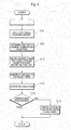
- Fig. 1 is a block diagram showing a configuration of a charging system employing a charging control device 1 according to an embodiment of the present invention.
- the charging control device 1 is connected to chargers 2 and a server 3 via a communication line.
- Rechargeable batteries 4 are connected respectively to the chargers 2 so as to be charged thereby.
- three rechargeable batteries 4 can be charged simultaneously.
- the charging control device 1 supplies power to the respective rechargeable batteries 2 within a range that does not exceed a maximum power supply from a system power network on the basis of information obtained from the chargers 2 and the server 3.
- the charger 2 charges the rechargeable battery 4 connected thereto using the power supplied from the charging control device 1. Further, the charger 2 obtains information such as a remaining charge of the rechargeable battery 4 connected thereto, and transmits the obtained information to the charging control device 1. Furthermore, a sensor or the like for obtaining environment-related information such as a peripheral temperature of the rechargeable battery 4 is provided in the interior of the charger 2, and the charger 2 also transmits this information to the charging control device 1.
- the server 3 provides the charging control device 1 with information required to predict a power consumption of the rechargeable battery 4, information required to predict a time at which use of an electric vehicle currently being charged will begin, and information relating to a lifespan of the battery.
- Fig. 2 is a block diagram showing a functional configuration of the charging control device 1.
- the charging control device 1 includes a remaining charge acquisition unit 101, a use start time prediction unit 102, a power consumption prediction unit 103 , a lifespan information acquisition unit 104, an environmental information acquisition unit 105, a charging plan updating unit 106, a resource plan storage unit 107, a charging plan storage unit 108, and a power adjustment unit 109.
- a specialized or general-purpose computer including a CPU, memory such as a ROM and a RAM, an external storage device for storing various types of information, an input interface, an output interface, a communication interface, and a bus connecting these components may be used as the charging control device 1.
- the charging control device 1 may be constituted by a single computer or a plurality of computers connected to each other via a communication line.
- the remaining charge acquisition unit 101, the use start time prediction unit 102, the power consumption prediction unit 103, the lifespan information acquisition unit 104, the environmental information acquisition unit 105, the charging plan updating unit 106, and the power adjustment unit 109 correspond to functional modules realized by having the CPU execute a predetermined program stored in the ROM or the like.
- the resource plan storage unit 107 and the charging plan storage unit 108 are packaged in the external storage device.
- the remaining charge acquisition unit 101 obtains a remaining charge of the rechargeable battery 4 connected to the charger 2.
- the remaining charge acquisition unit 101 obtains the remaining charge of the rechargeable battery 4 after receiving notification from the charger 2 that the rechargeable battery 4 has been connected, and transmits the obtained remaining charge to the charging plan updating unit 106.
- the remaining charge acquisition unit 101 may also obtain the remaining charge of the rechargeable battery 4 at fixed time intervals. Further, in a case where information indicating the remaining charge is stored in the rechargeable battery 4 itself, the remaining charge acquisition unit 101 may obtain the remaining charge directly from the rechargeable battery 4.
- the use start time prediction unit 102 predicts a time at which use of the electric vehicle currently being charged will next start.
- the use start time prediction unit 102 obtains information relating to a user of the vehicle from the server 3, and predicts the time at which the user will next start to use the electric vehicle on the basis of this information. More specifically, for example, the use start time prediction unit 102 may obtain history information indicating past use start times and positions of the vehicle, and determine an average use start time. Alternatively, the use start time prediction unit 102 may obtain schedule information input by the user him/herself, and retrieve a time of a following journey from this information. The time at which the user will start to use the electric vehicle may also be predicted by applying another preferred method to the information relating to the user of the vehicle. A prediction result is transmitted to the charging plan updating unit 106.
- the power consumption prediction unit 103 predicts an amount of power to be consumed by the electric vehicle during the following journey, or in other words up to a following charging operation.
- the power consumption prediction unit 103 obtains information relating to a use plan and a use history of the electric vehicle from the server 3, and predicts the amount of power to be consumed by the user during the next use of the electric vehicle on the basis of this information.
- a prediction result is transmitted to the charging plan updating unit 106.
- the power consumption prediction unit 103 may obtain a history of GPS information generated by the user during a past use of the electric vehicle, and predict the amount of power to be consumed from a total traveled distance at that time.
- the power consumption prediction unit 103 may obtain the schedule information input by the user him/herself, retrieve a planned journey from this information, calculate a travel distance required to reach a destination, and predict the power consumption from the calculated travel distance. Further, a travel log of the electric vehicle may be used. The travel log includes information such as a speed and a traveled distance during use of the vehicle, a time of vehicle use, and height differences along a traveled route. By taking into consideration the height differences along the traveled route in addition to the speed and traveled distance information, the power consumption can be predicted more accurately.
- the lifespan information acquisition unit 104 obtains lifespan information relating to the rechargeable battery 4 connected to the charger 2.
- the lifespan information is information expressing a degree of deterioration of the rechargeable battery 4. More specifically, an internal resistance value of the rechargeable battery 4, a number of past charging operations performed on the rechargeable battery 4, a log of voltage variation during previous uses, and so on may be used as the lifespan information.
- the lifespan information acquisition unit 104 obtains statistical information and the like relating to the remaining charge of the rechargeable battery during charging from the server 3, generates the lifespan information of the rechargeable battery 4 from this information, and transmits the lifespan information to the charging plan updating unit 106. Note that when lifespan information such as an upper limit number of charging operations is stored in the rechargeable battery 4 itself, the lifespan information may be obtained from the rechargeable battery 4 directly rather than via the server 3.
- the environmental information acquisition unit 105 obtains information relating to the environment of the battery, such as a peripheral temperature of the rechargeable battery 4, from the charger 2, and transmits the information to the charging plan updating unit 106. More specifically, information such as air temperature, humidity, and weather conditions at a charging location is obtained. Information such as an amount of sunlight, a wind direction, and an amount of rainfall may also be obtained.
- the charging plan updating unit 106 creates a charging plan for each charger 2, and updates the resource plan storage unit 107 and the charging plan storage unit 108.
- the charging plan updating unit 106 creates the charging plan on the basis of the remaining charge of the rechargeable battery 4 obtained from the remaining charge acquisition unit 101, the use start time of the electric vehicle obtained from the use start time prediction unit 102, the power consumption obtained from the power consumption prediction unit 103, the lifespan information of the rechargeable battery 4 obtained from the lifespan information acquisition unit 104, and the environmental information obtained by the environmental information acquisition unit 105 so that the rechargeable battery 4 reaches a target remaining charge before the use start time of the electric vehicle.
- the resource plan storage unit 107 stores a resource plan indicating a relationship between a total amount of power to be used by all of the chargers 2 connected to the charging control device 1 and time.
- the resource plan is created by the charging plan updating unit 106, and may take the form of graph data such as those shown in Figs. 8 to 13 , for example.
- the charging plan storage unit 108 stores the charging plans of the rechargeable batteries 4 connected to the chargers 2.
- the charging plan includes a post-charging target remaining charge of the rechargeable battery 4 and a charging process up to achievement of the target remaining charge.
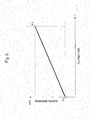
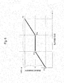
- the charging plan may take the form of graph data such as those shown in Figs. 5 to 7 , for example.
- the charging plan is created by the charging plan updating unit 106 for each charger and transmitted to the power adjustment unit 109.
- the power adjustment unit 109 distributes the power supplied from the power network to the respective chargers 2 in accordance with the charging plans of the respective chargers 2.
- Step S1 the charging control device 1 performs monitoring to determine whether a rechargeable battery 4 has been connected to or detached from the charger 2. When a rechargeable battery 4 has been attached or detached (Yes), the processing advances to Step S2.
- Step S2 the charging control device 1 obtains the remaining charge, use start time, power consumption, and lifespan information of all of the rechargeable batteries 4 connected to the chargers 2.
- Step S3 the charging control device 1 creates the charging plans. Further, in Step S4, the charging control device 1 distributes power to the respective chargers 2 in accordance with the created charging plans.
- the target remaining charge of the rechargeable battery 4 is calculated on the basis of the remaining charge and the predicted power consumption of the rechargeable battery 4.
- the target remaining charge may be obtained by adding a remaining charge corresponding to the predicted power consumption to a current remaining charge of the rechargeable battery 4.
- the target remaining charge may be set at a larger value, taking into account self-discharge of the rechargeable battery 4. Note that when the calculated target remaining charge is larger than a chargeable capacity of the rechargeable battery 4, the capacity of the rechargeable battery 4 is set as the target remaining charge.
- Step S12 a determination is made on the basis of the lifespan information of the rechargeable battery 4 as to whether or not to perform charging while taking the deterioration of the rechargeable battery 4 into account. More specifically, it may be determined that charging is to be performed while taking the deterioration into account when the internal resistance of the rechargeable battery 4 equals or exceeds a fixed value. Alternatively, whether or not the number of charging operations of the rechargeable battery 4 equals or exceeds a fixed number, whether or not a voltage reduction speed during a previous use equals or exceeds a fixed value, and so on may be used as a determination reference.
- the determination as to whether or not to perform charging while taking the deterioration of the rechargeable battery 4 into account may be made in consideration of information other than the lifespan information of the rechargeable battery 4 itself. For example, it may be determined that charging is to be performed while taking the deterioration of the rechargeable battery 4 into account when a period from a current time to the use start time equals or exceeds a fixed period, or when the peripheral temperature of the charger 2 equals or exceeds a fixed temperature. The determination as to whether or not to perform charging while taking the deterioration of the rechargeable battery 4 into account may also be made using other factors linked to deterioration of the rechargeable battery 4. Furthermore, the user may choose whether or not to perform charging while taking the deterioration of the rechargeable battery 4 into account.
- Step S13 a charging plan with which the target remaining charge is reached before the use start time of the electric vehicle is created.
- the charging plan updating unit 106 creates the charging plan such that when the peripheral temperature of the electric vehicle, obtained via the environmental information acquisition unit 105, equals or exceeds a predetermined value, the remaining charge of the rechargeable battery 4 is maintained at or below a predetermined value for as long as possible during the charging period.
- Figs. 5 to 7 are graphs showing an elapsed time on the abscissa and the remaining charge of the rechargeable battery on the ordinate.
- P1 represents a condition of the rechargeable battery at the start of charging
- P2 represents a condition of the rechargeable battery at the use start time of the electric vehicle (when charging is complete).
- a coordinate of P1 on the ordinate corresponds to the current remaining charge of the battery, obtained by the remaining charge acquisition unit 101.
- a coordinate of P2 on the abscissa corresponds to the use start time of the electric vehicle, obtained from the use start time prediction unit 102, while a coordinate of P2 on the ordinate corresponds to the post-charging target remaining charge.
- P1 and P2 are linked by a straight line.
- charging is performed continuously at a constant fixed charging speed up to the use start time.
- the line linking P1 and P2 may be a monotonically increasing curve rather than a straight line.
- a period (P3-P4) in which charging is not performed is provided between P1 and P2.
- intersections between a straight line bisecting P1-P2 in an ordinate direction and two straight lines trisecting P1 and P2 in an abscissa direction are set respectively as P3 and P4, and P1, P3, P4, P2 are joined by line segments. Note that a number of periods in which charging is not performed may be increased. Further, during the charging periods, charging need not be performed at a fixed charging speed.
- a charging start time (P5) is calculated from the charging time required for the rechargeable battery to reach the target remaining charge so that charging is completed exactly at the use start time, and charging is not performed until the charging start time.
- P5 a straight line expressing a relationship between the elapsed time and the remaining charge of the rechargeable battery 4 when the charger 2 outputs a maximum amount of power that can be output thereby is drawn so as to pass through P2, a point at which the remaining charge of the rechargeable battery becomes equal to P1 is set as P5, and P1, P5, P2 are joined by a straight line serving as the charging start time.
- the charging start time may be determined on the assumption that charging will be performed using a smaller amount of power than the maximum output of the charger 2.
- the remaining charge of the rechargeable battery 4 is not increased during the period up to P5, and therefore, in comparison with the examples shown in Figs. 5 and 6 , a condition in which the remaining charge of the rechargeable battery 4 is equal to P1 is maintained for a maximum length of the charging period.
- a condition in which the remaining charge is small can be maintained for a long time, and therefore this example corresponds to a suitable charging plan for a case in which the peripheral temperature is high.
- the charging plan updating unit 106 preferably creates a charging plan such as that shown in Fig. 7 .
- a time average of the remaining charge of the rechargeable battery 4 during the charging period is smaller in the example of Fig. 7 than in the examples of Figs. 5 and 6 . Therefore, by determining a predetermined remaining charge threshold on the basis of the peripheral temperature of the electric vehicle and creating the charging plan so that the time average of the remaining charge of the rechargeable battery 4 during the charging period does not exceed the remaining charge threshold, for example, deterioration of the rechargeable battery can be prevented from advancing even under a different charging plan to the charging plan shown in Fig. 7 . For example, as long as the time average of the remaining charge does not exceed the remaining charge threshold, a continuous charging plan such as that shown in Fig. 5 or an intermittent charging plan such as that shown in Fig. 6 may be used.
- the charging plan updating unit 106 may recreate the charging plan such that the charging start time of P5 is brought forward.
- the remaining charge may be varied less rapidly by providing a period in which charging is not performed, as in the charging plan shown in Fig. 6 .
- the threshold may be determined on the basis of the lifespan information of the rechargeable battery.
- Step S11 to Step S13 The processing of Step S11 to Step S13 is performed on all of the rechargeable batteries 4 connected to the chargers 2.
- the charging plan updating unit 106 creates the resource plan in Step S14 on the basis of all of the created charging plans.
- a rechargeable battery 4 is connected only to a first charger 2, and that the charging plan for the first charger 2 is that shown in Fig. 5 .
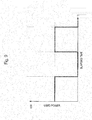
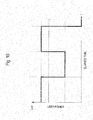
- a relationship between the elapsed time and a used power for executing the charging plan of Fig. 5 is expressed in the form of a graph shown in Fig. 8 .
- the abscissa on Fig. 8 shows the elapsed time, and the ordinate shows the power used by the charger.
- the resource plan in a case where a rechargeable battery 4 is connected only to the first charger 2 is as shown in Fig. 8 .
- a new rechargeable battery 4 is connected to a second charger 2, and that the charging plan for the second charger 2 is that shown in Fig. 6 .
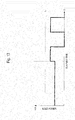
- the relationship between the elapsed time and the used power for executing the charging plan of Fig. 6 is expressed in the form of a graph shown in Fig. 9 .
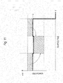
- the used power is a total amount of power used by the two chargers 2, and therefore this resource plan takes a form shown in Fig. 10 .
- the charging plan updating unit 106 determines whether or not the created resource plan satisfies a usable power amount condition.
- the usable power amount is an agreed power amount or an amount of power that can be supplied by the power network, for example.
- the usable power amount may be obtained by subtracting an amount of power used by devices other than the chargers 2 from the amount of power that can be supplied by the power network.
- the charging plan updating unit 106 determines that the created resource plan does not satisfy the usable power amount condition (No), and then advances to Step S16.
- the charging plan updating unit 106 determines that the created resource plan satisfies the usable power amount condition (Yes), updates the charging plan storage unit 108 and the resource plan storage unit 107, and then transmits the charging plans to the power adjustment unit 109, whereupon the processing is terminated.
- Step S16 the charging plan updating unit 106 modifies the resource plan so that the resource plan satisfies the usable power amount condition, and then recreates charging plans in accordance with the modified resource plan.
- the part of the power that exceeds L on the resource plan of Fig. 10 may be shifted to another period having leeway in the power amount.
- the charging plan updating unit 106 recreates the charging plan for the first charger 2 on the basis of the modified resource plan.
- the charging plan is modified from the graph shown in Fig. 5 to a graph shown by a solid line in Fig. 12 .
- the resource plan may also be modified as shown in Fig. 13 .
- the second rechargeable battery 4 is charged when charging of the first rechargeable battery 4 is complete. In so doing, the charging plan for the first charger does not have to be modified and only the charging start time is modified on the charging plan for the second charger.
- the charging plan updating unit 106 updates the charging plan storage unit 108 and the resource plan storage unit 107 and then transmits the charging plans of the respective chargers 2 to the power adjustment unit 109, whereupon the processing is terminated.
- the power adjustment unit 109 distributes the power supplied from the power network to the respective chargers 2 in accordance with the received charging plans of the respective chargers 2.
- the charging plan can be created while taking into consideration the prevention of deterioration of the rechargeable battery for the electric vehicle.
- a situation in which the rechargeable battery is left for a long time in a high-temperature location when the remaining charge thereof is high can be avoided.
- the charging plan can be created on the basis of the resource plan that takes into account the usable power amount, and therefore a plurality of rechargeable batteries can be charged simultaneously.
- the present invention may be used to perform charging while taking into consideration the prevention of deterioration of a rechargeable battery for an electric vehicle in a household having an electric automobile charger, a commercial establishment such as a shopping center, a gas station, or a convenience store, a community center or an administrative institution, or a public facility such as a hospital.
- the present invention may also be used in a case where power not exceeding an agreed power amount is supplied to a plurality of chargers. Further, the present invention may be used as means for supplying power not exceeding an agreed power amount to chargers for electric automobiles located in various locations from an identical power supply source by remotely controlling the respective chargers.
- a charging control device including:
- the charging control device further including a use start time prediction unit that predicts a use start time of the electric vehicle, wherein, when the charging plan updating unit determines to take the deterioration of the rechargeable battery into consideration and the temperature is equal to or higher than the predetermined value, the charging plan updating unit calculates a charging start time from a charging time required for the rechargeable battery to reach the target remaining charge so that charging is completed exactly at the use start time, and creates the charging plan such that charging is not performed until the charging start time.
- the charging plan updating unit creates the charging plan so that variation in the remaining charge per unit time during the charging period does not exceed a predetermined threshold.
- the charging control device further including a power consumption prediction unit that predicts a power amount to be consumed by the electric vehicle during a following journey, wherein the charging plan updating unit determines the target remaining charge on the basis of the predicted power amount.
- the charging control device according to any of Notes 1 to 4, wherein the charging plan updating unit creates charging plans for a plurality of rechargeable batteries, creates a resource plan including a relationship between time and a power amount required to execute the charging plans of the respective rechargeable batteries, and when the created resource plan exceeds a usable power amount, corrects the resource plan and recreates charging plans of the respective rechargeable batteries in accordance with the corrected resource plan.
- a charging control method including the steps of:
- the present invention is suitable for performing charging while taking into consideration the prevention of deterioration of a rechargeable battery.
Landscapes
- Engineering & Computer Science (AREA)
- Power Engineering (AREA)
- Mechanical Engineering (AREA)
- Transportation (AREA)
- General Chemical & Material Sciences (AREA)
- Electrochemistry (AREA)
- Chemical Kinetics & Catalysis (AREA)
- Chemical & Material Sciences (AREA)
- Manufacturing & Machinery (AREA)
- Life Sciences & Earth Sciences (AREA)
- Sustainable Development (AREA)
- Sustainable Energy (AREA)
- Charge And Discharge Circuits For Batteries Or The Like (AREA)
Applications Claiming Priority (2)
| Application Number | Priority Date | Filing Date | Title |
|---|---|---|---|
| JP2011001303 | 2011-01-06 | ||
| PCT/JP2011/080426 WO2012093638A1 (ja) | 2011-01-06 | 2011-12-28 | 充電制御装置、充電制御方法、及びプログラム |
Publications (2)
| Publication Number | Publication Date |
|---|---|
| EP2662949A1 true EP2662949A1 (de) | 2013-11-13 |
| EP2662949A4 EP2662949A4 (de) | 2017-04-19 |
Family
ID=46457495
Family Applications (1)
| Application Number | Title | Priority Date | Filing Date |
|---|---|---|---|
| EP11855005.2A Withdrawn EP2662949A4 (de) | 2011-01-06 | 2011-12-28 | Ladesteuervorrichtung, ladesteuerverfahren und programm dafür |
Country Status (4)
| Country | Link |
|---|---|
| US (1) | US20130285608A1 (de) |
| EP (1) | EP2662949A4 (de) |
| JP (1) | JP5854287B2 (de) |
| WO (1) | WO2012093638A1 (de) |
Cited By (12)
| Publication number | Priority date | Publication date | Assignee | Title |
|---|---|---|---|---|
| WO2015036827A1 (en) * | 2013-09-11 | 2015-03-19 | Toyota Jidosha Kabushiki Kaisha | Charging system of in-vehicle battery and charging method of in-vehicle battery |
| CN106323331A (zh) * | 2016-08-22 | 2017-01-11 | 乐视控股(北京)有限公司 | 预测车辆行驶里程的方法及装置 |
| EP3386061A4 (de) * | 2015-12-01 | 2019-01-16 | Omron Corporation | Batterieladevorrichtung, batterieladesystem und batterieladeverfahren |
| WO2020144007A1 (fr) * | 2019-01-10 | 2020-07-16 | Renault S.A.S | Méthode de charge d'une batterie d'accumulateurs par une borne de charge |
| WO2020167324A1 (en) | 2019-02-15 | 2020-08-20 | Cora Aero Llc | Desired departure temperature for a battery in a vehicle |
| CN111845451A (zh) * | 2019-04-29 | 2020-10-30 | 大众汽车有限公司 | 用于给电驱动机动车的牵引电池组充电的方法 |
| EP3767782A1 (de) * | 2014-11-13 | 2021-01-20 | Samsung Electronics Co., Ltd. | Elektronische vorrichtung und batterieladungs-/-entladungssteuerungsverfahren dafür |
| US10913373B2 (en) | 2016-04-20 | 2021-02-09 | Innogy Se | Charging system and method for operating a charging system |
| WO2021126280A1 (en) * | 2019-12-18 | 2021-06-24 | Gm Cruise Holdings Llc | Dynamic state-of-charge bounds for vehicle battery management |
| CN113507159A (zh) * | 2021-09-10 | 2021-10-15 | 南通明诺电动科技股份有限公司 | 一种基于电动汽车的充电控制系统及方法 |
| EP4091869A1 (de) * | 2021-05-18 | 2022-11-23 | Volkswagen Ag | Verfahren und anordnung zur lade-/entladesteuerung eines hochvolt-batteriesystems |
| WO2023105095A3 (de) * | 2021-12-12 | 2024-01-11 | eClever Entwicklungs OHG | Fahrzeug- und fahrzeugführerspezifisches routing |
Families Citing this family (28)
| Publication number | Priority date | Publication date | Assignee | Title |
|---|---|---|---|---|
| DE102011082623B3 (de) * | 2011-09-13 | 2013-02-07 | Continental Automotive Gmbh | Verfahren zum Laden eines in ein Elektrokraftfahrzeug eingebauten Akkumulators |
| JP6280687B2 (ja) * | 2012-09-05 | 2018-02-14 | 株式会社日立製作所 | 充放電システム、および充放電装置 |
| JP6096447B2 (ja) * | 2012-09-13 | 2017-03-15 | 株式会社東芝 | 蓄電池管理装置および蓄電池管理システム |
| WO2014050735A1 (ja) * | 2012-09-27 | 2014-04-03 | 日本電気株式会社 | 情報処理装置、電力需要体、情報処理方法、及びプログラム |
| JP6081817B2 (ja) | 2013-02-26 | 2017-02-15 | 三菱重工業株式会社 | 車載器およびev管理システム |
| US20140266039A1 (en) * | 2013-03-14 | 2014-09-18 | General Electric Company | Systems and Methods for Controlling a Charging Device |
| US9906076B2 (en) * | 2013-11-11 | 2018-02-27 | Samsung Electro-Mechanics Co., Ltd. | Non-contact type power transmitting coil and non-contact type power supplying apparatus |
| EP3608867A1 (de) * | 2014-03-19 | 2020-02-12 | Nissan Motor Co., Ltd. | Bedienerverwaltungsvorrichtung, bedienerverwaltungssystem und bedienerverwaltungsverfahren |
| JP6582737B2 (ja) * | 2015-08-25 | 2019-10-02 | 住友電気工業株式会社 | 充放電制御装置及び制御プログラム |
| JP6254139B2 (ja) * | 2015-11-28 | 2017-12-27 | 本田技研工業株式会社 | 電力供給システム及び輸送機器、並びに、電力伝送方法 |
| US9931515B2 (en) * | 2015-12-17 | 2018-04-03 | Novartis Ag | Powered case for electro-active medical device battery management |
| TW201742350A (zh) * | 2016-05-30 | 2017-12-01 | 微星科技股份有限公司 | 可充電的電池及其充電方法 |
| US11336107B2 (en) * | 2016-07-13 | 2022-05-17 | Sony Corporation | Information processing device, information processing system, and charging method |
| JP2018102084A (ja) * | 2016-12-21 | 2018-06-28 | トヨタ自動車株式会社 | 充電制御装置 |
| WO2019030985A1 (ja) * | 2017-08-10 | 2019-02-14 | 住友電気工業株式会社 | 制御装置、制御方法、およびコンピュータプログラム |
| JP2019118219A (ja) * | 2017-12-27 | 2019-07-18 | トヨタ自動車株式会社 | 走行エネルギー分配システム、走行エネルギー分配方法および走行エネルギー分配プログラム |
| KR102544462B1 (ko) * | 2018-01-25 | 2023-06-19 | 삼성전자 주식회사 | 배터리를 포함하는 전자 장치 및 이의 충전구간을 제어하는 방법 |
| JP7060486B2 (ja) * | 2018-10-10 | 2022-04-26 | 本田技研工業株式会社 | 充電制御装置 |
| JP7273492B2 (ja) * | 2018-12-10 | 2023-05-15 | 株式会社Subaru | 車両支援システム |
| CN112740507A (zh) * | 2019-03-04 | 2021-04-30 | 松下知识产权经营株式会社 | 信息处理方法及信息处理系统 |
| JP7251459B2 (ja) | 2019-12-09 | 2023-04-04 | トヨタ自動車株式会社 | 電力管理システム、及びサーバ |
| JP7264032B2 (ja) | 2019-12-10 | 2023-04-25 | トヨタ自動車株式会社 | サーバ、及び電力管理システム |
| DE102020133254A1 (de) | 2020-12-14 | 2022-06-15 | Audi Aktiengesellschaft | Verfahren zum Betreiben einer Ladeinfrastrukturanordnung sowie entsprechende Ladeinfrastrukturanordnung |
| US20220285970A1 (en) * | 2021-03-05 | 2022-09-08 | RHiot, Inc. | Managing power between wearable devices |
| CN113625712B (zh) * | 2021-08-04 | 2023-10-31 | 国网浙江省电力有限公司嘉兴供电公司 | 一种基于回归分析算法的巡检机器人工作调整方法 |
| CN114368312A (zh) * | 2022-01-11 | 2022-04-19 | 青岛特来电新能源科技有限公司 | 车辆信息的处理方法、装置、电子设备及介质 |
| CN114597992A (zh) * | 2022-02-23 | 2022-06-07 | 深圳市道通合创新能源有限公司 | 一种充电截止电量的获取和设置方法、充电管理系统 |
| CN117141293B (zh) * | 2023-11-01 | 2024-04-30 | 深圳市安德普电源科技有限公司 | 充电桩的智能控制方法及系统 |
Family Cites Families (27)
| Publication number | Priority date | Publication date | Assignee | Title |
|---|---|---|---|---|
| US4424476A (en) * | 1981-01-16 | 1984-01-03 | General Electric Company | Controlled fast charger |
| US4553081A (en) * | 1982-06-07 | 1985-11-12 | Norand Corporation | Portable battery powered system |
| US4845419A (en) * | 1985-11-12 | 1989-07-04 | Norand Corporation | Automatic control means providing a low-power responsive signal, particularly for initiating data preservation operation |
| EP0539640A1 (de) * | 1991-10-30 | 1993-05-05 | Texas Instruments Limited | Batterieverbesserungen |
| JPH0630532A (ja) * | 1992-07-08 | 1994-02-04 | Toyota Autom Loom Works Ltd | 充電装置 |
| JPH0714615A (ja) * | 1993-06-28 | 1995-01-17 | Minolta Co Ltd | カメラの電源システム |
| JPH07250437A (ja) * | 1994-03-09 | 1995-09-26 | Canon Inc | 太陽電池を用いた電源装置 |
| JP3554057B2 (ja) * | 1995-02-06 | 2004-08-11 | 本田技研工業株式会社 | 電気自動車用蓄電池充電制御装置 |
| US5712795A (en) * | 1995-10-02 | 1998-01-27 | Alaris Medical Systems, Inc. | Power management system |
| CN1055574C (zh) * | 1996-03-06 | 2000-08-16 | 杨泰和 | 自动监控运转之引擎驱动式蓄电瓶辅助充电系统 |
| JPH09259935A (ja) * | 1996-03-19 | 1997-10-03 | Toshiba Corp | 2次電池充放電回数検出装置 |
| JP3415740B2 (ja) * | 1997-04-14 | 2003-06-09 | 本田技研工業株式会社 | バッテリ充電装置 |
| JPH11185825A (ja) * | 1997-12-25 | 1999-07-09 | Hitachi Koki Co Ltd | 電池の充電法 |
| JP2000253596A (ja) * | 1999-02-26 | 2000-09-14 | Matsushita Electric Ind Co Ltd | 2次電池充電装置と充電方法 |
| JP2000287378A (ja) * | 1999-03-29 | 2000-10-13 | Sony Corp | 充電装置、充電方法および電子機器 |
| JP2001292533A (ja) * | 2000-04-04 | 2001-10-19 | Japan Storage Battery Co Ltd | 電気自動車の電池管理装置 |
| US6707273B1 (en) * | 2002-07-18 | 2004-03-16 | Electronic Design & Sales, Inc. | Temperature/voltage controlled battery charging circuit |
| US7429849B2 (en) * | 2003-11-26 | 2008-09-30 | Toyo System Co., Ltd. | Method and apparatus for confirming the charge amount and degradation state of a battery, a storage medium, an information processing apparatus, and an electronic apparatus |
| JP4207984B2 (ja) * | 2006-06-19 | 2009-01-14 | 東京電力株式会社 | 充電システム及びその制御方法 |
| JP4946749B2 (ja) * | 2007-09-14 | 2012-06-06 | 三菱自動車工業株式会社 | 車両のバッテリ制御装置 |
| JP4333798B2 (ja) * | 2007-11-30 | 2009-09-16 | トヨタ自動車株式会社 | 充電制御装置および充電制御方法 |
| JP4715881B2 (ja) * | 2008-07-25 | 2011-07-06 | トヨタ自動車株式会社 | 電源システムおよびそれを備えた車両 |
| US8255176B2 (en) * | 2008-08-07 | 2012-08-28 | Research In Motion Limited | Systems and methods for monitoring deterioration of a rechargeable battery |
| WO2010084599A1 (ja) * | 2009-01-23 | 2010-07-29 | トヨタ自動車株式会社 | 充電制御装置 |
| JP2011001303A (ja) | 2009-06-19 | 2011-01-06 | Mandom Corp | リップグロス製品 |
| US20120256752A1 (en) * | 2011-04-06 | 2012-10-11 | James William Musser | System and method to extend operating life of rechargable batteries using battery charge management |
| CN103635350A (zh) * | 2011-06-17 | 2014-03-12 | 丰田自动车株式会社 | 电动车辆以及电动车辆的控制方法 |
-
2011
- 2011-12-28 US US13/977,813 patent/US20130285608A1/en not_active Abandoned
- 2011-12-28 JP JP2012551848A patent/JP5854287B2/ja not_active Expired - Fee Related
- 2011-12-28 EP EP11855005.2A patent/EP2662949A4/de not_active Withdrawn
- 2011-12-28 WO PCT/JP2011/080426 patent/WO2012093638A1/ja active Application Filing
Cited By (19)
| Publication number | Priority date | Publication date | Assignee | Title |
|---|---|---|---|---|
| WO2015036827A1 (en) * | 2013-09-11 | 2015-03-19 | Toyota Jidosha Kabushiki Kaisha | Charging system of in-vehicle battery and charging method of in-vehicle battery |
| EP3767782A1 (de) * | 2014-11-13 | 2021-01-20 | Samsung Electronics Co., Ltd. | Elektronische vorrichtung und batterieladungs-/-entladungssteuerungsverfahren dafür |
| EP3386061A4 (de) * | 2015-12-01 | 2019-01-16 | Omron Corporation | Batterieladevorrichtung, batterieladesystem und batterieladeverfahren |
| US10688876B2 (en) | 2015-12-01 | 2020-06-23 | Omron Corporation | Battery charging device, battery charging system, and battery charging method |
| EP3445607B1 (de) * | 2016-04-20 | 2021-03-03 | innogy SE | Ladesystem und verfahren zum betreiben eines ladesystems |
| US10913373B2 (en) | 2016-04-20 | 2021-02-09 | Innogy Se | Charging system and method for operating a charging system |
| CN106323331A (zh) * | 2016-08-22 | 2017-01-11 | 乐视控股(北京)有限公司 | 预测车辆行驶里程的方法及装置 |
| WO2020144007A1 (fr) * | 2019-01-10 | 2020-07-16 | Renault S.A.S | Méthode de charge d'une batterie d'accumulateurs par une borne de charge |
| FR3091788A1 (fr) * | 2019-01-10 | 2020-07-17 | Renault S.A.S. | Méthode de charge d’une batterie d’accumulateurs par une borne de charge |
| WO2020167324A1 (en) | 2019-02-15 | 2020-08-20 | Cora Aero Llc | Desired departure temperature for a battery in a vehicle |
| EP3924210A4 (de) * | 2019-02-15 | 2022-11-09 | Wisk Aero LLC | Erwünschte ausgangstemperatur für eine batterie in einem fahrzeug |
| EP3733444A1 (de) * | 2019-04-29 | 2020-11-04 | Volkswagen Ag | Verfahren zum laden einer traktionsbatterie eines elektrisch angetriebenen kraftfahrzeugs |
| CN111845451A (zh) * | 2019-04-29 | 2020-10-30 | 大众汽车有限公司 | 用于给电驱动机动车的牵引电池组充电的方法 |
| WO2021126280A1 (en) * | 2019-12-18 | 2021-06-24 | Gm Cruise Holdings Llc | Dynamic state-of-charge bounds for vehicle battery management |
| US11390184B2 (en) | 2019-12-18 | 2022-07-19 | Gm Cruise Holdings Llc | Dynamic state-of-charge bounds for vehicle battery management |
| EP4091869A1 (de) * | 2021-05-18 | 2022-11-23 | Volkswagen Ag | Verfahren und anordnung zur lade-/entladesteuerung eines hochvolt-batteriesystems |
| CN113507159A (zh) * | 2021-09-10 | 2021-10-15 | 南通明诺电动科技股份有限公司 | 一种基于电动汽车的充电控制系统及方法 |
| CN113507159B (zh) * | 2021-09-10 | 2021-12-28 | 南通明诺电动科技股份有限公司 | 一种基于电动汽车的充电控制系统及方法 |
| WO2023105095A3 (de) * | 2021-12-12 | 2024-01-11 | eClever Entwicklungs OHG | Fahrzeug- und fahrzeugführerspezifisches routing |
Also Published As
| Publication number | Publication date |
|---|---|
| US20130285608A1 (en) | 2013-10-31 |
| JP5854287B2 (ja) | 2016-02-09 |
| JPWO2012093638A1 (ja) | 2014-06-09 |
| WO2012093638A1 (ja) | 2012-07-12 |
| EP2662949A4 (de) | 2017-04-19 |
Similar Documents
| Publication | Publication Date | Title |
|---|---|---|
| EP2662949A1 (de) | Ladesteuervorrichtung, ladesteuerverfahren und programm dafür | |
| US10882411B2 (en) | Smart charging schedules for battery systems and associated methods for electrified vehicles | |
| US10464547B2 (en) | Vehicle with model-based route energy prediction, correction, and optimization | |
| JP5837129B2 (ja) | スマートグリッドシステム | |
| JP5372987B2 (ja) | 電力マネジメントシステム | |
| US20150165915A1 (en) | Vehicle charging system | |
| JP5776017B2 (ja) | 蓄電池充電計画支援システム | |
| US20140336965A1 (en) | Charge/discharge assist device | |
| US10776168B2 (en) | Vehicle and computing system | |
| JP2000209707A (ja) | 電気自動車の充電計画装置 | |
| JP2010280250A (ja) | 動力発生源制御装置 | |
| CN103608992A (zh) | 充电系统、电力管理服务器、车辆管理服务器和电力管理程序 | |
| US20230066396A1 (en) | Method of providing guidance for use of electric power of electric vehicle | |
| US20120150378A1 (en) | Determination and Usage of Reserve Energy in Stored Energy Systems | |
| CN111204257A (zh) | 用于电蓄能器的充电方法 | |
| JP2014207814A (ja) | 電源装置および電源装置の制御方法 | |
| EP2951048B1 (de) | Batterieinstandhaltungssystem | |
| JP5533725B2 (ja) | 車両の充電装置 | |
| US20180375344A1 (en) | Situational battery charging | |
| CN115071490A (zh) | 控制系统和能量管理方法 | |
| CN112018794A (zh) | 管理装置、管理方法及存储介质 | |
| JP2022123329A (ja) | 充電制御装置、移動体、充電制御システム及び充電制御方法 | |
| JP2020077026A (ja) | 位置情報提供システム | |
| CN111016736A (zh) | 充电控制装置 | |
| JP2021058006A (ja) | 蓄電装置の充放電制御装置 |
Legal Events
| Date | Code | Title | Description |
|---|---|---|---|
| PUAI | Public reference made under article 153(3) epc to a published international application that has entered the european phase |
Free format text: ORIGINAL CODE: 0009012 |
|
| 17P | Request for examination filed |
Effective date: 20130806 |
|
| AK | Designated contracting states |
Kind code of ref document: A1 Designated state(s): AL AT BE BG CH CY CZ DE DK EE ES FI FR GB GR HR HU IE IS IT LI LT LU LV MC MK MT NL NO PL PT RO RS SE SI SK SM TR |
|
| DAX | Request for extension of the european patent (deleted) | ||
| RA4 | Supplementary search report drawn up and despatched (corrected) |
Effective date: 20170317 |
|
| RIC1 | Information provided on ipc code assigned before grant |
Ipc: B60L 3/00 20060101ALI20170311BHEP Ipc: H01M 10/44 20060101ALI20170311BHEP Ipc: H01M 10/42 20060101ALI20170311BHEP Ipc: H01M 10/0525 20100101ALI20170311BHEP Ipc: H02J 7/00 20060101ALI20170311BHEP Ipc: B60L 3/12 20060101ALI20170311BHEP Ipc: H01M 10/48 20060101ALI20170311BHEP Ipc: B60L 11/18 20060101ALI20170311BHEP Ipc: H02J 7/02 20160101AFI20170311BHEP |
|
| STAA | Information on the status of an ep patent application or granted ep patent |
Free format text: STATUS: THE APPLICATION IS DEEMED TO BE WITHDRAWN |
|
| 18D | Application deemed to be withdrawn |
Effective date: 20171017 |