EP2657779B1 - Bilderzeugungsvorrichtung - Google Patents
Bilderzeugungsvorrichtung Download PDFInfo
- Publication number
- EP2657779B1 EP2657779B1 EP13163263.0A EP13163263A EP2657779B1 EP 2657779 B1 EP2657779 B1 EP 2657779B1 EP 13163263 A EP13163263 A EP 13163263A EP 2657779 B1 EP2657779 B1 EP 2657779B1
- Authority
- EP
- European Patent Office
- Prior art keywords
- paper
- bias
- unit
- photosensitive drum
- image forming
- Prior art date
- Legal status (The legal status is an assumption and is not a legal conclusion. Google has not performed a legal analysis and makes no representation as to the accuracy of the status listed.)
- Not-in-force
Links
- 239000004020 conductor Substances 0.000 claims description 15
- 238000007599 discharging Methods 0.000 description 22
- 238000006386 neutralization reaction Methods 0.000 description 13
- 238000010586 diagram Methods 0.000 description 10
- 230000010287 polarization Effects 0.000 description 7
- 238000012545 processing Methods 0.000 description 7
- 238000004140 cleaning Methods 0.000 description 5
- 238000011144 upstream manufacturing Methods 0.000 description 5
- 238000010438 heat treatment Methods 0.000 description 4
- 230000002093 peripheral effect Effects 0.000 description 3
- 230000015572 biosynthetic process Effects 0.000 description 2
- 238000013019 agitation Methods 0.000 description 1
- 239000000969 carrier Substances 0.000 description 1
- 230000007423 decrease Effects 0.000 description 1
- 230000000994 depressogenic effect Effects 0.000 description 1
- 238000001514 detection method Methods 0.000 description 1
- 230000000694 effects Effects 0.000 description 1
- 229920001971 elastomer Polymers 0.000 description 1
- 230000005611 electricity Effects 0.000 description 1
- 229920005558 epichlorohydrin rubber Polymers 0.000 description 1
- 238000002844 melting Methods 0.000 description 1
- 230000008018 melting Effects 0.000 description 1
- 238000012805 post-processing Methods 0.000 description 1
- 230000002265 prevention Effects 0.000 description 1
- 230000003068 static effect Effects 0.000 description 1
Images


Classifications
-
- G—PHYSICS
- G03—PHOTOGRAPHY; CINEMATOGRAPHY; ANALOGOUS TECHNIQUES USING WAVES OTHER THAN OPTICAL WAVES; ELECTROGRAPHY; HOLOGRAPHY
- G03G—ELECTROGRAPHY; ELECTROPHOTOGRAPHY; MAGNETOGRAPHY
- G03G15/00—Apparatus for electrographic processes using a charge pattern
- G03G15/22—Apparatus for electrographic processes using a charge pattern involving the combination of more than one step according to groups G03G13/02 - G03G13/20
- G03G15/24—Apparatus for electrographic processes using a charge pattern involving the combination of more than one step according to groups G03G13/02 - G03G13/20 whereby at least two steps are performed simultaneously
-
- G—PHYSICS
- G03—PHOTOGRAPHY; CINEMATOGRAPHY; ANALOGOUS TECHNIQUES USING WAVES OTHER THAN OPTICAL WAVES; ELECTROGRAPHY; HOLOGRAPHY
- G03G—ELECTROGRAPHY; ELECTROPHOTOGRAPHY; MAGNETOGRAPHY
- G03G15/00—Apparatus for electrographic processes using a charge pattern
- G03G15/02—Apparatus for electrographic processes using a charge pattern for laying down a uniform charge, e.g. for sensitising; Corona discharge devices
- G03G15/0266—Arrangements for controlling the amount of charge
-
- G—PHYSICS
- G03—PHOTOGRAPHY; CINEMATOGRAPHY; ANALOGOUS TECHNIQUES USING WAVES OTHER THAN OPTICAL WAVES; ELECTROGRAPHY; HOLOGRAPHY
- G03G—ELECTROGRAPHY; ELECTROPHOTOGRAPHY; MAGNETOGRAPHY
- G03G15/00—Apparatus for electrographic processes using a charge pattern
- G03G15/14—Apparatus for electrographic processes using a charge pattern for transferring a pattern to a second base
- G03G15/16—Apparatus for electrographic processes using a charge pattern for transferring a pattern to a second base of a toner pattern, e.g. a powder pattern, e.g. magnetic transfer
- G03G15/1665—Apparatus for electrographic processes using a charge pattern for transferring a pattern to a second base of a toner pattern, e.g. a powder pattern, e.g. magnetic transfer by introducing the second base in the nip formed by the recording member and at least one transfer member, e.g. in combination with bias or heat
- G03G15/167—Apparatus for electrographic processes using a charge pattern for transferring a pattern to a second base of a toner pattern, e.g. a powder pattern, e.g. magnetic transfer by introducing the second base in the nip formed by the recording member and at least one transfer member, e.g. in combination with bias or heat at least one of the recording member or the transfer member being rotatable during the transfer
- G03G15/1675—Apparatus for electrographic processes using a charge pattern for transferring a pattern to a second base of a toner pattern, e.g. a powder pattern, e.g. magnetic transfer by introducing the second base in the nip formed by the recording member and at least one transfer member, e.g. in combination with bias or heat at least one of the recording member or the transfer member being rotatable during the transfer with means for controlling the bias applied in the transfer nip
Definitions
- the present disclosure relates to an image forming apparatus that can form an image on a transfer object using a toner.
- a type of image forming apparatus has been known that forms an image on a sheet of paper by first forming a toner image on a surface of a photosensitive drum and then transferring the toner image to a sheet of paper (transfer object).
- Such an image forming apparatus is provided with a charging roller (charging member) that electrically charges the surface of the photosensitive drum.
- the charging roller must be electrically conductive and therefore includes an ion conductive material.
- charging devices have been proposed by JP-A-H10-048914 and JP-AH10-228158 that alleviate polarization of the ion conductive material by applying to the charging roller a reversed polarity bias to that charged on the photosensitive drum when no image is formed on the paper.
- JP-A-2003/091146 an image forming apparatus with an electrical charging roller is known.
- EP 0 563 478 A2 an electrophotographic copying machine is known.
- the present disclosure relates to an image forming apparatus that includes an image carrier, a charging member, a developing unit, a transfer member, a first bias application unit, a second bias application unit, and a control unit.
- the charging member contains an ion conductive material and is arranged in contact with or in proximity to the image carrier to electrically charge a surface of the image car rier.
- the developing unit forms a toner image on the surface of the image carrier.
- the transfer member transfers the toner image formed on the surface of the image carrier to a transfer object.
- the first bias application unit applies a first bias to the charging member.
- the second bias application unit applies a predetermined bias to the transfer member.
- the control unit controls the first bias application unit and the second bias application unit.
- the control unit controls the first bias application unit not to apply the first bias to the charging member in a non-image forming period in which a toner image is not formed on the image carrier.
- the control unit controls the second bias application unit to apply to the transfer member a second bias, which is a bias that can electrically charge the surface of the image carrier, in the non-image forming period.
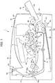
- FIG. 1 is a diagram illustrating arrangement of components of the printer 1 according to the embodiment.
- the printer 1 as the image forming apparatus includes: an apparatus main body M; an image forming unit GK that forms a predetermined toner image on paper T as a sheet-shaped image transfer object based on predetermined image information; and a paper feeding/discharging part KH that feeds the paper T to the image forming unit GK and discharges the paper T on which the toner image is formed.
- An external shape of the apparatus main body M is composed of a casing body BD as a housing.
- the image forming unit GK includes a photosensitive drum 2 as an image carrier (photosensitive body), a charging unit 10, a laser scanner unit 4 as an exposure unit, a developing unit 16, a toner cartridge 5, a toner supply unit 6, a drum-cleaning unit 11, a neutralization unit 12, a transfer roller 8, and a fuser 9.
- the paper feeding/discharging part KH includes a paper feeding cassette 52, a manual feeding portion 64, a paper path L for the paper T, a pair of registration rollers 80, and a paper discharging unit 50.
- Charging by the charging unit 10, exposure by the laser scanner unit 4, development by the developing unit 16, transfer by the transfer roller 8, neutralization by the neutralization unit 12, and cleaning by the drum cleaning unit 11 are sequentially performed in order, from an upstream side to a downstream side along a surface of the photosensitive drum 2 in the image forming unit GK.
- the photosensitive drum 2 consists of a cylindrical member, and functions as a photosensitive body or an image carrier.
- the photosensitive drum 2 is disposed to be rotatable in a direction indicated by an arrow about a rotational shaft extending in a direction orthogonal to a direction in which the paper T is conveyed through the paper path L.
- An electrostatic latent image may be formed on the surface of the photosensitive drum 2.
- the charging unit 10 is arranged opposite to the surface of the photosensitive drum 2. Details of the charging unit 10 are described later.
- the laser scanner unit 4 functions as an exposure unit, and is disposed to be spaced apart from the surface of the photosensitive drum 2.
- the laser scanner unit 4 is configured with a laser light source, a polygonal mirror, a polygonal-mirror-driving motor and the like, none of which are illustrated in the drawings.
- the laser scanner unit 4 scans and exposes the surface of the photosensitive drum 2 based on image information that is input from an external device such as a PC (personal computer). By being scanned and exposed by the laser scanner unit 4, an electric charge in the exposed portion on the surface of the photosensitive drum 2 is removed. In this way, an electrostatic latent image is formed on a surface of the photosensitive drum 2.
- the developing unit 16 (developing portion) is provided in correspondence with the photosensitive drum 2, and is arranged opposite to the surface of the photosensitive drum 2.
- the developing unit 16 causes single color toner (usually black toner) to adhere to an electrostatic latent image formed on the photosensitive drum 2, thereby forming a single color toner image on the surface of the photosensitive drum 2.
- the developing unit 16 is configured with a developing roller 17 arranged opposite to the surface of the photosensitive drum 2, an agitation roller 18 for agitating toner, and the like.
- the toner cartridge 5 is provided in correspondence with the developing unit 16, and stores toner to be supplied to the developing unit 16.
- the toner supply unit 6 is provided in correspondence with the toner cartridge 5 and the developing unit 16, and supplies toner stored in the toner cartridge 5 to the developing unit 16.
- the toner supply unit 6 and the developing unit 16 are connected with each other via a toner feed passage that is not illustrated in the drawings.
- the transfer roller 8 transfers a toner image, which has been developed on the surface of the photosensitive drum 2, onto the paper T.
- a transfer bias application unit (not shown) applies a transfer bias to the transfer roller 8 for transferring a toner image formed on the photosensitive drum 2 onto the paper T.
- the transfer roller 8 is configured to be rotatable in contact with the photosensitive drum 2.
- the paper T conveyed through the paper path L is interposed between the photosensitive drum 2 and the transfer roller 8.
- the interposed paper T is pressed against the surface of the photosensitive drum 2.
- a transfer nip N is formed between the photosensitive drum 2 and the transfer roller 8. In the transfer nip N, a toner image developed on the photosensitive drum 2 is transferred onto the paper T.
- the neutralization unit 12 is arranged opposite to the surface of the photosensitive drum 2. By radiating light on the surface of the photosensitive drum 2, the neutralization unit 12 removes static electricity (neutralizes electrical charge) on the surface of the photosensitive drum 2, onto which the transfer has been performed.
- the drum-cleaning unit 11 is arranged opposite to the surface of the photosensitive drum 2.
- the drum-cleaning unit 11 removes toner and attached matter remaining on the surface of the photosensitive drum 2, and conveys the toner and the like thus removed to a predetermined collecting mechanism for collection thereof.
- the fusing unit 9 fixes the toner on the paper T.
- the fusing unit 9 includes a heating rotator 9a that is heated by a heater, and a pressurizing rotator 9b that is brought into pressure-contact with the heat rotator 9a.
- the heating rotor 9a and the pressing rotor 9b interpose, press and convey the paper T with the toner image transferred thereon.
- the paper T is conveyed in a state of being sandwiched between the heating rotator 9a and the pressurizing rotator 9b, whereby the toner transferred to the paper T is fused and compressed and fixed to the paper T.
- one paper feeding cassette 52 for storing paper T is disposed in a lower portion of the apparatus main body M.
- the paper feeding cassette 52 is configured to be capable of being horizontally withdrawn from a right side (right side in FIG. 1 ) of the apparatus main body M.
- the paper feeding cassette 52 includes a paper tray 60 on which the sheets of paper T are placed.
- the paper feeding cassette 52 stores the sheets of paper T stacked on the sheet of paper Tray 60.
- a sheet of paper T placed on the sheet of paper tray 60 is fed to the paper feed path L by a cassette feeding unit 51 disposed in an end part of the paper feeding cassette 52 on a side of feeding the sheet of paper (at a right end portion of FIG. 1 ).
- the cassette feeding unit 51 includes a double feed prevention mechanism consisting of: a forward feed roller 61 for picking up the paper T on the paper tray 60; and a pair of paper feeding rollers 63 for feeding the sheet of paper T one by one to the paper path L.
- a manual paper feed unit 64 is provided on the right side (right side in FIG. 1 ) in the apparatus main body M.
- the manual feeding portion 64 is provided primarily for the purpose of feeding paper T that is different in size and type from the paper T stored in the paper feeding cassette 52 to the apparatus main body M.
- the manual paper feed unit 64 includes a manual feeding tray 65 and a paper feeding roller 66 configuring a part of the front face of the apparatus main body M in a closed state.
- a lower end of the manual feeding tray 65 is rotatably attached to the apparatus main body M in the vicinity of the paper feeding roller 66 (openable and closable).
- a sheet of paper T is placed on the manual feeding tray 65 while it is open.
- the paper feeding roller 66 feeds a sheet of paper T placed on the manual feeding tray 65 while it is open to the manual feeding path La.
- a paper discharging unit 50 is provided to an upper side of the apparatus main body M.
- the paper discharging unit 50 discharges the paper T to the outside of the device main body M by way of a third pair of rollers 53. Details of the paper discharging unit 50 are described later.
- the paper path L which conveys paper T includes: a first paper path L1 from the cassette feeding unit 51 to the transfer nip N; a second paper path L2 from the transfer nip N to the fusing unit 9; a third paper path L3 from the fusing unit 9 to the paper discharging unit 50; the manual feeding path La that guides paper fed from the manual feeding unit 64 to the first paper path L1; and a reverse paper path Lb that reverses and returns the paper that is fed from a downstream side to an upstream side in the third paper feed path L3 to the first paper path L1.
- first junction P1 and a second junction P2 are provided in the route of the first paper path L1.
- a first branch portion Q1 is provided in the route of the third paper path L3.
- the first junction P1 is a junction where the manual feeding path La joins the first paper feed path L1.
- the second junction P2 is a junction where the reverse paper path Lb joins the first paper path L1. In the first branch portion Q1, the reverse paper path Lb branches off the third paper path L3.
- the first branch portion Q1 has a first pair of rollers 54a and a second pair of rollers 54b.
- the same roller concurrently serves as one of the first pair of rollers 54a and one of the second pair of rollers 54b.
- a sensor for detecting the paper T and a pair of registration rollers 80 for skew (oblique feeding) compensation of the paper T and timing adjustment between formation of the toner image in the image forming unit GK and feed of the paper T are disposed in the route of the first paper path L1 (more specifically, between the second junction P2 and the transfer roller 8).
- the sensor is disposed immediately before the pair of registration rollers 80 in the conveyance direction of the paper T (on the upstream side in the conveyance direction).
- the pair of registration rollers 80 conveys the paper T by performing the aforementioned compensation and timing adjustment based on detection signal information from the sensor.
- the reverse paper path Lb is a paper path provided for the purpose of making a surface (unprinted surface), which is opposite to a surface that has already been printed, face the photosensitive drum 2 when performing duplex printing on the paper T.
- the paper T conveyed from the first branch portion Q1 to the paper discharging unit 50 side by way of the first pair of rollers 54a can be reversed and then returned to the first paper path L1 by way of the second pair of rollers 54b, and the paper T can be conveyed to the upstream side of the pair of registration rollers 80 disposed on the upstream side of the transfer roller 8.
- a predetermined toner image is transferred to the unprinted surface of the sheet of paper T that has been reversed by the reverse paper path Lb.
- the paper discharging unit 50 is formed in an end portion of the third paper path L3.
- the paper discharging unit 50 is disposed in an upper portion of the apparatus main body M.
- the paper discharging unit 50 is open toward the right side (right side in FIG. 1 , and the manual paper feed unit 64 side) of the apparatus main body M.
- the paper discharging unit 50 discharges the paper T conveyed from the third paper path L3 to the outside of the apparatus main body M by way of the third pair of rollers 53.
- a discharged paper collection part M1 is formed in the vicinity of the opening of the paper discharging unit 50.
- the discharged paper collection part M1 is formed on an upper face (outer face) of the apparatus main body M.
- the discharged paper collection part M1 is a portion of the upper face of the apparatus main body M formed to be depressed downward.
- the bottom face of the discharged paper collection part M1 constitutes a part of the upper face of the apparatus main body M.
- the paper T on which a predetermined toner image is formed and which is discharged from the paper discharging unit 50, is stacked and collected in the discharged paper collection part M1.
- a sensor for detecting paper is disposed in a predetermined position on each paper path.
- the charging unit 10 uniformly charges the surface of the photosensitive drum 2. More specifically, the charging unit 10 includes a charging roller 10a (charging member). The charging roller 10a is arranged in contact with or in proximity to the photosensitive drum 2. In a case in which the charging roller 10a is arranged in proximity to the photosensitive drum 2, a distance between the charging roller 10a and the photosensitive drum 2 is approximately 50 to 100 um.
- the charging roller 10a includes an ion conductive material for electrically charging the surface of the photosensitive drum 2.
- the charging roller 10a includes a cylindrical ion conductive material (not illustrated) provided with a metallic shaft (not illustrated) as a central shaft.
- the ion conductive material is, for example, conductive rubber such as epichlorohydrin rubber.
- FIG. 2 is a diagram illustrating the photosensitive drum 2, the charging roller 10a, the transfer roller 8, the first bias application unit 101, the second bias application unit 102, and the control unit 103.
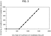
- FIG. 3 is a diagram showing an example of a relationship between the potential of the surface of the photosensitive drum 2 and a voltage of the surface of the charging roller 10a.
- FIG. 4 is a diagram showing an example of a relationship between the potential of the surface of the photosensitive drum 2 and a rotation time of the photosensitive drum 2.
- the above described printer 1 further includes the first bias application unit 101, the second bias application unit 102, and the control unit 103.
- the first bias application unit 101 applies a first bias to the charging roller 10a, under control of the control unit 103.
- the second bias application unit 102 applies a predetermined bias to the transfer roller 8, under control of the control unit 103.
- the control unit 103 controls the first bias application unit 101 and the second bias application unit 102. More specifically, the control unit 103 controls the first bias application unit 101 not to apply the first bias to the charging roller 10a in a non-image forming period. In addition, the control unit 103 controls the second bias application unit 102 to apply the second bias, which is a bias that can electrically charge the surface of the photosensitive drum 2, to the transfer roller 8 in the non-image forming period.
- the non-image forming period is a time period in which a toner image is not formed on the photosensitive drum 2 after completion of a job as an instruction for forming an image on the paper T. In other words, the non-image forming period is a time period in which post processing is performed after the completion of the job (approximately 10 seconds, for example).
- a potential difference between the photosensitive drum 2 and the charging roller 10a is greater than a voltage at which electrical discharge starts between the photosensitive drum 2 and the charging roller 10a.
- a potential at a surface of the photosensitive drum 2 at the contact part or the proximity part of the photosensitive drum 2 and the charging roller 10a is greater than a voltage at which electrical discharge starts between the photosensitive drum 2 and the charging roller 10a.
- the contact part is a position at which the photosensitive drum 2 and the charging roller 10a contacts each other, and a peripheral position at a periphery of this contact position, in a case in which the photosensitive drum 2 and the charging roller 10a are arranged in contact with each other.
- the proximity part is a closest proximity position at which the photosensitive drum 2 and the charging roller 10a are closest to each other, and a proximity position at a periphery of this closest proximity position, in a case in which the photosensitive drum 2 and the charging roller 10a are arranged in proximity to each other.
- the surface of the photosensitive drum 2 is electrically charged.
- a potential difference between the surface of the photosensitive drum 2 and the surface of the charging roller 10a is greater than 600 V, electrical discharge occurs between the photosensitive drum 2 and the charging roller 10a.
- the second bias application unit 102 applies the second bias to the transfer roller 8
- the surface of the photosensitive drum 2 is electrically charged.
- the potential of the surface of the photosensitive drum 2 decreases due to dark decay.
- an external diameter of the photosensitive drum 2 is ⁇ 30 mm
- processing speed is 200 mm/sec
- an angle between the contact position between the transfer roller 8 and the photosensitive drum 2 (first position A1) and the contact part (proximity part) between the charging roller 10a and the photosensitive drum 2 (second position A2) is 192.6°
- an amount of time required for the photosensitive drum 2 to rotate from the first position A1 to the second position A2 is 252 msec.
- the surface of the photosensitive drum 2 is electrically charged to +800 V at the first position A1.
- the potential of the surface of the photosensitive drum 2 (+700 V) at the second position A2 is greater than the voltage at which electrical discharge starts between the photosensitive drum 2 and the charging roller 10a (600 V).
- an upper limit of the second bias is a value smaller than a withstand voltage of the photosensitive drum 2.
- the neutralization unit 12 does not neutralize the photosensitive drum 2. In other words, the neutralization unit 12 does not irradiate the surface of the photosensitive drum 2 with light.
- control unit 103 controls the first bias application unit 101 to apply the first bias to the charging roller 10a in the image forming period.
- the first bias application unit 101 applies +1100 V as the first bias to the charging roller 10a. This charges the surface of the photosensitive drum 2 to +500 V.
- control unit 103 controls the second bias application unit 102 to apply a third bias, which is of a reversed polarity to the second bias, to the transfer roller 8 in the image forming period.
- the third bias is a bias for transferring the toner image, which has been formed on the surface of the photosensitive drum 2, onto the paper T.
- the third bias is approximately -1000 to - 1200 V.
- the image forming period is a period in which a toner image is formed on the photosensitive drum 2 by the charging unit 10, the developing unit 16 and the like and the toner image is then transferred onto the paper T by the transfer roller 8 based on a job as an instruction for forming an image on the paper T.
- the second bias application unit 102 applies a bias of a reversed polarty to the third bias (as a specific example, +500 V) to the transfer roller 8 in order to return the toner adhering to the transfer roller 8 to the photosensitive drum 2.
- a bias of a reversed polarty to the third bias (as a specific example, +500 V) to the transfer roller 8 in order to return the toner adhering to the transfer roller 8 to the photosensitive drum 2.
- FIG. 5 is a diagram showing a relationship between resistance and charging time of the charging roller 10a in a case of the present embodiment and in a case without employing the present embodiment.
- the present embodiment provides a smaller resistance value than in a case without performing the control of the present embodiment (in a case of not applying the second bias to the transfer roller 8 in the non-image forming period).
- FIG. 5 shows that the present embodiment alleviates polarization of the ion conductive material included in the charging roller 10a.
- the paper T stored in the paper feeding cassette 52 is fed to the first paper path L1 by way of the forward feed roller 61 and the pair of feed rollers 63, and is subsequently conveyed through the first junction P1 and the first paper path L1 to the pair of registration rollers 80.
- the pair of registration rollers 80 performs skew compensation of the paper T and timing adjustment with respect to the toner image.
- the paper T discharged from the pair of registration rollers 80 is introduced between the photosensitive drum 2 and the transfer roller 8 (i.e. in the transfer nip N) through the first paper path L1. Then, a toner image is transferred onto the paper T between the photosensitive drum 2 and the transfer roller 8.
- the paper T is discharged from between the photosensitive drum 2 and the transfer roller 8, and is introduced to a fusing nip between the heating rotor 9a and the pressing rotor 9b in the fusing unit 9 through the second paper path L2.
- the toner TN is then fused in the fusing nip and the toner TN is fixed onto the paper T.
- the paper T is conveyed through the third paper path L3 to the paper discharging unit 50 by way of the first pair of rollers 54a, and is discharged from the paper discharging unit 50 to the discharged paper collection part M1 by way of the third pair of rollers 53.
- the paper T placed on the manual feeding tray 65 is dispatched to the manual feeding path La by the paper feeding roller 66, and then conveyed to the pair of registration rollers 80 via the first junction P1 and the first paper path L1. Operations thereafter are the same as in the case of single-side printing on the paper T housed in the paper feeding cassette 52 described above, and therefore descriptions thereof are omitted.
- printing is completed by discharging the paper T printed on one side from the paper discharging unit 50 to the discharged paper collection part M1.
- the paper T printed on one side is reversed compared to the single-side printing and reconveyed to the pair of registration rollers 80 via the reverse paper path Lb to thereby perform printing on both faces of the paper T.
- the operations are similar to the operations of single-sided printing as described above, until the paper T with single-sided printing performed thereon is discharged from the paper discharging unit 50 by way of the third pair of rollers 53.
- the third pair of rollers 53 stops the rotation, and is rotated in an opposite direction, in a state in which the paper T with single-sided printing performed thereon is held by the third pair of rollers 53. In this way, by rotating the third pair of rollers 53 in the opposite direction, the paper T held by the third pair of rollers 53 is conveyed to the opposite direction through the third paper path L3 (direction from the paper discharging unit 50 to the first branch portion Q1).
- the paper T when the paper T is conveyed through the third paper path L3 in the opposite direction, the paper T is introduced between the second pair of rollers 54b (instead of the first pair of rollers 54a). The paper T then joins the first paper path L1 through the reverse paper path Lb and the second junction P2. Here, the paper T is reversed from the orientation thereof in printing on the one side.
- the correction or adjustment is performed on the paper T by way of the pair of registration rollers 80, and the paper T is introduced between the photosensitive drum 2 and the transfer roller 8 via the first paper path L1.
- the paper T is introduced between the photosensitive drum 2 and the transfer roller 8 via the first paper path L1.
- a toner image is transferred to the unprinted surface and duplex printing is thus realized.
- FIG. 6 is a flow chart describing characteristic operations of the printer 1.
- Step ST1 the control unit 103 determines whether the printer 1 is in the non-image forming period or not. If the printer 1 is in the non-image forming period (YES), the control unit 103 advances the processing to Step ST2. If the printer 1 is not in the non-image forming period (NO), the control unit 103 advances the processing to Step ST5.
- Step ST1 the control unit 103 performs an operation for alleviating polarization of the ion conductive material included in the charging roller 10a. More specifically, the following processing takes place.
- Step ST2 the control unit 103 turns off the first bias.
- the control unit 103 controls the first bias application unit 101 such that the first bias is not applied to the charging roller 10a by the first bias application unit 101.
- Step ST3 the control unit 103 turns off the neutralization unit 12. In other words, the control unit 103 controls the neutralization unit 12 not to irradiate the photosensitive drum 2 with light from the neutralization unit 12.
- Step ST4 the control unit 103 controls the second bias application unit 102 such that the second bias is applied to the transfer roller 8 by the second bias application unit 102. After the Step ST4, the processing terminates.
- Step ST1 the control unit 103 forms an image on the paper T. More specifically, the general operation of the printer 1 described above takes place. In summary, the following processing takes place.
- Step ST5 the control unit 103 turns on the neutralization unit 12.
- the control unit 103 controls the neutralization unit 12 to irradiate the photosensitive drum 2 with light from the neutralization unit 12.
- Step ST6 the control unit 103 controls the first bias application unit 101 to apply the first bias to the charging roller 10a by the first bias application unit 101.
- Step ST7 the control unit 103 controls the second bias application unit 102 to apply the third bias to the transfer roller 8 by the second bias application unit 102.
- the control unit 103 makes the determination of Step ST1. In a case in which a job has been completed, the control unit 103 makes an YES determination, again in Step ST1.
- the printer 1 of the present embodiment provides the following effects.
- the printer 1 of the present embodiment includes: the control unit 103 that controls the first bias application unit 101 and the second bias application unit 102.
- the control unit 103 controls the first bias application unit 101 not to apply the first bias to the charging roller 10a in the non-image forming period.
- the control unit 103 controls the second bias application unit 102 to apply the second bias, which is a bias that can electrically charge the surface of the photosensitive drum 2, to the transfer roller 8 in the non-image forming period.
- a potential difference between the photosensitive drum 2 and the charging roller 10a is greater than a voltage at which electrical discharge starts between the photosensitive drum 2 and the charging roller 10a.
- the printer 1 can thus alleviate polarization of the ion conductive material included in the charging roller 10a.
- control unit 103 controls the first bias application unit 101 to apply the first bias to the charging roller 10a in the image forming period.
- the control unit 103 controls the second bias application unit 102 to apply the third bias, which is of a reverse polarity to the second bias, to the transfer roller 8 in the image forming period.
- the printer 1 uses the second bias application unit 102 also in the image forming period.
- the printer 1 uses the second bias application unit 102, which is already provided, to apply the second bias to the transfer roller 8 in the non-image forming period.
- a monochrome printer 1 is exemplified in the present embodiment as the image forming apparatus; however, the present disclosure is not limited thereto and the image forming apparatus can be a color printer, a copy machine, a facsimile machine, and a multi-functional peripheral having functions thereof.
Landscapes
- Physics & Mathematics (AREA)
- General Physics & Mathematics (AREA)
- Engineering & Computer Science (AREA)
- Plasma & Fusion (AREA)
- Electrostatic Charge, Transfer And Separation In Electrography (AREA)
- Control Or Security For Electrophotography (AREA)
Claims (2)
- Bilderzeugungsvorrichtung (1), die Folgendes umfasst: einen Bildträger (2);
ein Ladeelement (10a), das ein ionenleitendes Material aufweist, wobei das Ladeelement (10a) in Kontakt mit oder nahe dem Bildträger (2) angeordnet ist und eine Oberfläche des Bildträgers (2) auflädt;
eine Entwicklereinheit (16), die konfiguriert ist, um ein Tonerbild auf der Oberfläche des Bildträgers (2) zu bilden;
ein Übertragungselement (8), das konfiguriert ist, um das Tonerbild, das auf der Oberfläche des Bildträgers (2) gebildet ist, auf ein Übertragungsobjekt zu übertragen;
dadurch gekennzeichnet, dass
die Bilderzeugungsvorrichtung (1) ferner Folgendes umfasst:eine erste Vorspannungsanlegeeinheit (101), die konfiguriert ist, um eine erste Vorspannung an das Ladeelement (10a) anzulegen;eine zweite Vorspannungsanlegeeinheit (102), die konfiguriert ist, um eine vorbestimmte Vorspannung an das Übertragungselement (8) anzulegen; undeine Steuereinheit (103), die konfiguriert ist, um die erste Vorspannungsanlegeeinheit (101) und die zweite Vorspannungsanlegeeinheit (102) zu steuern,wobei während eines nicht-bildbildenden Zeitraums, in dem das Tonerbild nicht auf dem Bildträger (2) gebildet wird, die Steuereinheit (103) konfiguriert ist, um die erste Vorspannungsanlegeeinheit (101) dahingehend zu steuern, die erste Vorspannung nicht auf das Ladeelement (10a) anzuwenden, und die zweite Vorspannungsanlegeeinheit (102) dahingehend zu steuern, eine zweite Vorspannung, die eine Vorspannung ist, die die Oberfläche des Bildträgers (2) elektrisch aufladen kann, an das Übertragungselement (8) anzulegen,und wobei in dem Fall, dass die Oberfläche des Bildträgers (2) durch das Übertragungselement (8), an das die zweite Vorspannung angelegt wurde, elektrisch aufgeladen ist, ein Potenzialunterschied zwischen dem Bildträger (2) und dem Ladeelement (10a) größer als eine Spannung ist, bei der eine elektrische Entladung zwischen dem Bildträger (2) und dem Ladeelement (10a) beginnt. - Bilderzeugungsvorrichtung (1) nach Anspruch 1, wobei während eines bildbildenden Zeitraums, in dem das Tonerbild auf dem Bildträger (2) gebildet wird und das Tonerbild auf das Übertragungsobjekt übertragen wird, die Steuereinheit (103) konfiguriert ist, um die erste Vorspannungsanlegeeinheit (101) dahingehend zu steuern, die erste Vorspannung auf das Ladeelement (10a) anzulegen, und
die zweite Vorspannungsanlegeeinheit (102) dahingehend zu steuern, eine dritte Vorspannung mit einer zu der zweiten Vorspannung umgekehrten Polarität an das Übertragungselement (8) anzulegen.
Applications Claiming Priority (1)
| Application Number | Priority Date | Filing Date | Title |
|---|---|---|---|
| JP2012098932A JP5629724B2 (ja) | 2012-04-24 | 2012-04-24 | 画像形成装置 |
Publications (3)
| Publication Number | Publication Date |
|---|---|
| EP2657779A2 EP2657779A2 (de) | 2013-10-30 |
| EP2657779A3 EP2657779A3 (de) | 2016-12-21 |
| EP2657779B1 true EP2657779B1 (de) | 2018-08-01 |
Family
ID=48050576
Family Applications (1)
| Application Number | Title | Priority Date | Filing Date |
|---|---|---|---|
| EP13163263.0A Not-in-force EP2657779B1 (de) | 2012-04-24 | 2013-04-11 | Bilderzeugungsvorrichtung |
Country Status (4)
| Country | Link |
|---|---|
| US (1) | US9063496B2 (de) |
| EP (1) | EP2657779B1 (de) |
| JP (1) | JP5629724B2 (de) |
| CN (1) | CN103376699B (de) |
Families Citing this family (2)
| Publication number | Priority date | Publication date | Assignee | Title |
|---|---|---|---|---|
| JP2016057580A (ja) * | 2014-09-12 | 2016-04-21 | キヤノン株式会社 | 画像形成装置 |
| JP2017040671A (ja) * | 2015-08-17 | 2017-02-23 | 富士ゼロックス株式会社 | 転写装置及び画像形成装置 |
Family Cites Families (10)
| Publication number | Priority date | Publication date | Assignee | Title |
|---|---|---|---|---|
| JP3221045B2 (ja) * | 1992-04-03 | 2001-10-22 | キヤノン株式会社 | 画像形成装置 |
| JPH07128999A (ja) * | 1993-11-01 | 1995-05-19 | Matsushita Electric Ind Co Ltd | 画像形成装置 |
| JPH0830073A (ja) * | 1994-07-19 | 1996-02-02 | Canon Inc | 画像形成装置の制御方法 |
| JPH1048914A (ja) | 1996-08-02 | 1998-02-20 | Canon Inc | 接触帯電装置、及び画像形成装置 |
| JPH10228158A (ja) * | 1997-02-13 | 1998-08-25 | Fuji Xerox Co Ltd | 接触帯電装置 |
| JP2003076164A (ja) * | 2001-08-31 | 2003-03-14 | Canon Inc | 画像形成装置 |
| JP2003091146A (ja) * | 2001-09-19 | 2003-03-28 | Fuji Xerox Co Ltd | 画像形成装置 |
| JP2003207993A (ja) * | 2002-01-16 | 2003-07-25 | Canon Inc | 帯電部材、画像形成装置、帯電方法およびプロセスカートリッジ |
| JP2004205583A (ja) * | 2002-12-24 | 2004-07-22 | Canon Inc | 画像形成装置 |
| KR20100062120A (ko) * | 2008-12-01 | 2010-06-10 | 삼성전자주식회사 | 화상형성장치 및 그 제어방법 |
-
2012
- 2012-04-24 JP JP2012098932A patent/JP5629724B2/ja not_active Expired - Fee Related
-
2013
- 2013-03-25 CN CN201310097064.3A patent/CN103376699B/zh not_active Expired - Fee Related
- 2013-04-11 EP EP13163263.0A patent/EP2657779B1/de not_active Not-in-force
- 2013-04-22 US US13/867,459 patent/US9063496B2/en not_active Expired - Fee Related
Non-Patent Citations (1)
| Title |
|---|
| None * |
Also Published As
| Publication number | Publication date |
|---|---|
| EP2657779A3 (de) | 2016-12-21 |
| CN103376699B (zh) | 2016-01-20 |
| JP2013228470A (ja) | 2013-11-07 |
| US20130279928A1 (en) | 2013-10-24 |
| EP2657779A2 (de) | 2013-10-30 |
| JP5629724B2 (ja) | 2014-11-26 |
| CN103376699A (zh) | 2013-10-30 |
| US9063496B2 (en) | 2015-06-23 |
Similar Documents
| Publication | Publication Date | Title |
|---|---|---|
| JP6111894B2 (ja) | 画像形成装置 | |
| US20120243919A1 (en) | Fixing device and image forming apparatus provided with the same | |
| US9223260B2 (en) | Image forming apparatus and fixing device | |
| JP5339750B2 (ja) | 画像形成装置 | |
| CN103676545B (zh) | 图像形成装置 | |
| US20140130694A1 (en) | Image forming apparatus | |
| CN106483803B (zh) | 图像形成系统、图像形成装置以及转印条件改变方法 | |
| EP2657779B1 (de) | Bilderzeugungsvorrichtung | |
| JP6740730B2 (ja) | 現像装置および画像形成装置 | |
| CN101482714A (zh) | 薄片输送装置、使用其的原稿输送装置和图像形成装置 | |
| JP4266541B2 (ja) | 画像形成装置 | |
| JP2015049471A (ja) | 画像形成装置 | |
| JP2019156574A (ja) | 検知装置、画像形成装置 | |
| JP2013228471A (ja) | 画像形成装置 | |
| JP5858863B2 (ja) | 画像形成装置 | |
| US10209660B2 (en) | Image formation device with toner increase mode | |
| JP2014059471A (ja) | 画像形成装置 | |
| JP5485245B2 (ja) | 画像形成装置の入力装置、および画像形成装置 | |
| US9150370B2 (en) | Sheet feeder and image forming apparatus incorporating same | |
| JP3174584B2 (ja) | 画像入出力装置 | |
| JP5991272B2 (ja) | 定着装置 | |
| JP2005099320A (ja) | 画像形成装置 | |
| US10591857B1 (en) | Image forming apparatus and control method of image forming apparatus efficiently during decolorization | |
| US20210088940A1 (en) | Image forming apparatus | |
| JP6021709B2 (ja) | 画像形成装置 |
Legal Events
| Date | Code | Title | Description |
|---|---|---|---|
| PUAI | Public reference made under article 153(3) epc to a published international application that has entered the european phase |
Free format text: ORIGINAL CODE: 0009012 |
|
| AK | Designated contracting states |
Kind code of ref document: A2 Designated state(s): AL AT BE BG CH CY CZ DE DK EE ES FI FR GB GR HR HU IE IS IT LI LT LU LV MC MK MT NL NO PL PT RO RS SE SI SK SM TR |
|
| AX | Request for extension of the european patent |
Extension state: BA ME |
|
| PUAL | Search report despatched |
Free format text: ORIGINAL CODE: 0009013 |
|
| AK | Designated contracting states |
Kind code of ref document: A3 Designated state(s): AL AT BE BG CH CY CZ DE DK EE ES FI FR GB GR HR HU IE IS IT LI LT LU LV MC MK MT NL NO PL PT RO RS SE SI SK SM TR |
|
| AX | Request for extension of the european patent |
Extension state: BA ME |
|
| RIC1 | Information provided on ipc code assigned before grant |
Ipc: G03G 15/02 20060101AFI20161115BHEP Ipc: G03G 15/16 20060101ALI20161115BHEP |
|
| STAA | Information on the status of an ep patent application or granted ep patent |
Free format text: STATUS: REQUEST FOR EXAMINATION WAS MADE |
|
| 17P | Request for examination filed |
Effective date: 20170523 |
|
| RBV | Designated contracting states (corrected) |
Designated state(s): AL AT BE BG CH CY CZ DE DK EE ES FI FR GB GR HR HU IE IS IT LI LT LU LV MC MK MT NL NO PL PT RO RS SE SI SK SM TR |
|
| GRAP | Despatch of communication of intention to grant a patent |
Free format text: ORIGINAL CODE: EPIDOSNIGR1 |
|
| STAA | Information on the status of an ep patent application or granted ep patent |
Free format text: STATUS: GRANT OF PATENT IS INTENDED |
|
| INTG | Intention to grant announced |
Effective date: 20180320 |
|
| RIN1 | Information on inventor provided before grant (corrected) |
Inventor name: WATANABE, TAKUJI Inventor name: SAKATO, SHINGO |
|
| GRAS | Grant fee paid |
Free format text: ORIGINAL CODE: EPIDOSNIGR3 |
|
| GRAA | (expected) grant |
Free format text: ORIGINAL CODE: 0009210 |
|
| STAA | Information on the status of an ep patent application or granted ep patent |
Free format text: STATUS: THE PATENT HAS BEEN GRANTED |
|
| AK | Designated contracting states |
Kind code of ref document: B1 Designated state(s): AL AT BE BG CH CY CZ DE DK EE ES FI FR GB GR HR HU IE IS IT LI LT LU LV MC MK MT NL NO PL PT RO RS SE SI SK SM TR |
|
| REG | Reference to a national code |
Ref country code: GB Ref legal event code: FG4D |
|
| REG | Reference to a national code |
Ref country code: CH Ref legal event code: EP Ref country code: AT Ref legal event code: REF Ref document number: 1024994 Country of ref document: AT Kind code of ref document: T Effective date: 20180815 |
|
| REG | Reference to a national code |
Ref country code: IE Ref legal event code: FG4D |
|
| REG | Reference to a national code |
Ref country code: DE Ref legal event code: R096 Ref document number: 602013041065 Country of ref document: DE |
|
| REG | Reference to a national code |
Ref country code: NL Ref legal event code: MP Effective date: 20180801 |
|
| REG | Reference to a national code |
Ref country code: LT Ref legal event code: MG4D |
|
| REG | Reference to a national code |
Ref country code: AT Ref legal event code: MK05 Ref document number: 1024994 Country of ref document: AT Kind code of ref document: T Effective date: 20180801 |
|
| PG25 | Lapsed in a contracting state [announced via postgrant information from national office to epo] |
Ref country code: NO Free format text: LAPSE BECAUSE OF FAILURE TO SUBMIT A TRANSLATION OF THE DESCRIPTION OR TO PAY THE FEE WITHIN THE PRESCRIBED TIME-LIMIT Effective date: 20181101 Ref country code: GR Free format text: LAPSE BECAUSE OF FAILURE TO SUBMIT A TRANSLATION OF THE DESCRIPTION OR TO PAY THE FEE WITHIN THE PRESCRIBED TIME-LIMIT Effective date: 20181102 Ref country code: SE Free format text: LAPSE BECAUSE OF FAILURE TO SUBMIT A TRANSLATION OF THE DESCRIPTION OR TO PAY THE FEE WITHIN THE PRESCRIBED TIME-LIMIT Effective date: 20180801 Ref country code: BG Free format text: LAPSE BECAUSE OF FAILURE TO SUBMIT A TRANSLATION OF THE DESCRIPTION OR TO PAY THE FEE WITHIN THE PRESCRIBED TIME-LIMIT Effective date: 20181101 Ref country code: NL Free format text: LAPSE BECAUSE OF FAILURE TO SUBMIT A TRANSLATION OF THE DESCRIPTION OR TO PAY THE FEE WITHIN THE PRESCRIBED TIME-LIMIT Effective date: 20180801 Ref country code: LT Free format text: LAPSE BECAUSE OF FAILURE TO SUBMIT A TRANSLATION OF THE DESCRIPTION OR TO PAY THE FEE WITHIN THE PRESCRIBED TIME-LIMIT Effective date: 20180801 Ref country code: PL Free format text: LAPSE BECAUSE OF FAILURE TO SUBMIT A TRANSLATION OF THE DESCRIPTION OR TO PAY THE FEE WITHIN THE PRESCRIBED TIME-LIMIT Effective date: 20180801 Ref country code: FI Free format text: LAPSE BECAUSE OF FAILURE TO SUBMIT A TRANSLATION OF THE DESCRIPTION OR TO PAY THE FEE WITHIN THE PRESCRIBED TIME-LIMIT Effective date: 20180801 Ref country code: IS Free format text: LAPSE BECAUSE OF FAILURE TO SUBMIT A TRANSLATION OF THE DESCRIPTION OR TO PAY THE FEE WITHIN THE PRESCRIBED TIME-LIMIT Effective date: 20181201 Ref country code: RS Free format text: LAPSE BECAUSE OF FAILURE TO SUBMIT A TRANSLATION OF THE DESCRIPTION OR TO PAY THE FEE WITHIN THE PRESCRIBED TIME-LIMIT Effective date: 20180801 Ref country code: AT Free format text: LAPSE BECAUSE OF FAILURE TO SUBMIT A TRANSLATION OF THE DESCRIPTION OR TO PAY THE FEE WITHIN THE PRESCRIBED TIME-LIMIT Effective date: 20180801 |
|
| PG25 | Lapsed in a contracting state [announced via postgrant information from national office to epo] |
Ref country code: AL Free format text: LAPSE BECAUSE OF FAILURE TO SUBMIT A TRANSLATION OF THE DESCRIPTION OR TO PAY THE FEE WITHIN THE PRESCRIBED TIME-LIMIT Effective date: 20180801 Ref country code: LV Free format text: LAPSE BECAUSE OF FAILURE TO SUBMIT A TRANSLATION OF THE DESCRIPTION OR TO PAY THE FEE WITHIN THE PRESCRIBED TIME-LIMIT Effective date: 20180801 Ref country code: HR Free format text: LAPSE BECAUSE OF FAILURE TO SUBMIT A TRANSLATION OF THE DESCRIPTION OR TO PAY THE FEE WITHIN THE PRESCRIBED TIME-LIMIT Effective date: 20180801 |
|
| PG25 | Lapsed in a contracting state [announced via postgrant information from national office to epo] |
Ref country code: RO Free format text: LAPSE BECAUSE OF FAILURE TO SUBMIT A TRANSLATION OF THE DESCRIPTION OR TO PAY THE FEE WITHIN THE PRESCRIBED TIME-LIMIT Effective date: 20180801 Ref country code: IT Free format text: LAPSE BECAUSE OF FAILURE TO SUBMIT A TRANSLATION OF THE DESCRIPTION OR TO PAY THE FEE WITHIN THE PRESCRIBED TIME-LIMIT Effective date: 20180801 Ref country code: EE Free format text: LAPSE BECAUSE OF FAILURE TO SUBMIT A TRANSLATION OF THE DESCRIPTION OR TO PAY THE FEE WITHIN THE PRESCRIBED TIME-LIMIT Effective date: 20180801 Ref country code: CZ Free format text: LAPSE BECAUSE OF FAILURE TO SUBMIT A TRANSLATION OF THE DESCRIPTION OR TO PAY THE FEE WITHIN THE PRESCRIBED TIME-LIMIT Effective date: 20180801 Ref country code: ES Free format text: LAPSE BECAUSE OF FAILURE TO SUBMIT A TRANSLATION OF THE DESCRIPTION OR TO PAY THE FEE WITHIN THE PRESCRIBED TIME-LIMIT Effective date: 20180801 |
|
| REG | Reference to a national code |
Ref country code: DE Ref legal event code: R097 Ref document number: 602013041065 Country of ref document: DE |
|
| PG25 | Lapsed in a contracting state [announced via postgrant information from national office to epo] |
Ref country code: SK Free format text: LAPSE BECAUSE OF FAILURE TO SUBMIT A TRANSLATION OF THE DESCRIPTION OR TO PAY THE FEE WITHIN THE PRESCRIBED TIME-LIMIT Effective date: 20180801 Ref country code: DK Free format text: LAPSE BECAUSE OF FAILURE TO SUBMIT A TRANSLATION OF THE DESCRIPTION OR TO PAY THE FEE WITHIN THE PRESCRIBED TIME-LIMIT Effective date: 20180801 Ref country code: SM Free format text: LAPSE BECAUSE OF FAILURE TO SUBMIT A TRANSLATION OF THE DESCRIPTION OR TO PAY THE FEE WITHIN THE PRESCRIBED TIME-LIMIT Effective date: 20180801 |
|
| PLBE | No opposition filed within time limit |
Free format text: ORIGINAL CODE: 0009261 |
|
| STAA | Information on the status of an ep patent application or granted ep patent |
Free format text: STATUS: NO OPPOSITION FILED WITHIN TIME LIMIT |
|
| 26N | No opposition filed |
Effective date: 20190503 |
|
| PG25 | Lapsed in a contracting state [announced via postgrant information from national office to epo] |
Ref country code: SI Free format text: LAPSE BECAUSE OF FAILURE TO SUBMIT A TRANSLATION OF THE DESCRIPTION OR TO PAY THE FEE WITHIN THE PRESCRIBED TIME-LIMIT Effective date: 20180801 |
|
| REG | Reference to a national code |
Ref country code: CH Ref legal event code: PL |
|
| REG | Reference to a national code |
Ref country code: BE Ref legal event code: MM Effective date: 20190430 |
|
| PG25 | Lapsed in a contracting state [announced via postgrant information from national office to epo] |
Ref country code: MC Free format text: LAPSE BECAUSE OF FAILURE TO SUBMIT A TRANSLATION OF THE DESCRIPTION OR TO PAY THE FEE WITHIN THE PRESCRIBED TIME-LIMIT Effective date: 20180801 Ref country code: LU Free format text: LAPSE BECAUSE OF NON-PAYMENT OF DUE FEES Effective date: 20190411 |
|
| PG25 | Lapsed in a contracting state [announced via postgrant information from national office to epo] |
Ref country code: LI Free format text: LAPSE BECAUSE OF NON-PAYMENT OF DUE FEES Effective date: 20190430 Ref country code: CH Free format text: LAPSE BECAUSE OF NON-PAYMENT OF DUE FEES Effective date: 20190430 |
|
| PG25 | Lapsed in a contracting state [announced via postgrant information from national office to epo] |
Ref country code: BE Free format text: LAPSE BECAUSE OF NON-PAYMENT OF DUE FEES Effective date: 20190430 |
|
| PG25 | Lapsed in a contracting state [announced via postgrant information from national office to epo] |
Ref country code: TR Free format text: LAPSE BECAUSE OF FAILURE TO SUBMIT A TRANSLATION OF THE DESCRIPTION OR TO PAY THE FEE WITHIN THE PRESCRIBED TIME-LIMIT Effective date: 20180801 |
|
| PG25 | Lapsed in a contracting state [announced via postgrant information from national office to epo] |
Ref country code: IE Free format text: LAPSE BECAUSE OF NON-PAYMENT OF DUE FEES Effective date: 20190411 |
|
| PG25 | Lapsed in a contracting state [announced via postgrant information from national office to epo] |
Ref country code: PT Free format text: LAPSE BECAUSE OF FAILURE TO SUBMIT A TRANSLATION OF THE DESCRIPTION OR TO PAY THE FEE WITHIN THE PRESCRIBED TIME-LIMIT Effective date: 20181201 |
|
| PGFP | Annual fee paid to national office [announced via postgrant information from national office to epo] |
Ref country code: FR Payment date: 20200312 Year of fee payment: 8 |
|
| PGFP | Annual fee paid to national office [announced via postgrant information from national office to epo] |
Ref country code: DE Payment date: 20200331 Year of fee payment: 8 |
|
| PGFP | Annual fee paid to national office [announced via postgrant information from national office to epo] |
Ref country code: GB Payment date: 20200401 Year of fee payment: 8 |
|
| PG25 | Lapsed in a contracting state [announced via postgrant information from national office to epo] |
Ref country code: CY Free format text: LAPSE BECAUSE OF FAILURE TO SUBMIT A TRANSLATION OF THE DESCRIPTION OR TO PAY THE FEE WITHIN THE PRESCRIBED TIME-LIMIT Effective date: 20180801 |
|
| PG25 | Lapsed in a contracting state [announced via postgrant information from national office to epo] |
Ref country code: MT Free format text: LAPSE BECAUSE OF FAILURE TO SUBMIT A TRANSLATION OF THE DESCRIPTION OR TO PAY THE FEE WITHIN THE PRESCRIBED TIME-LIMIT Effective date: 20180801 Ref country code: HU Free format text: LAPSE BECAUSE OF FAILURE TO SUBMIT A TRANSLATION OF THE DESCRIPTION OR TO PAY THE FEE WITHIN THE PRESCRIBED TIME-LIMIT; INVALID AB INITIO Effective date: 20130411 |
|
| REG | Reference to a national code |
Ref country code: DE Ref legal event code: R119 Ref document number: 602013041065 Country of ref document: DE |
|
| GBPC | Gb: european patent ceased through non-payment of renewal fee |
Effective date: 20210411 |
|
| PG25 | Lapsed in a contracting state [announced via postgrant information from national office to epo] |
Ref country code: DE Free format text: LAPSE BECAUSE OF NON-PAYMENT OF DUE FEES Effective date: 20211103 Ref country code: FR Free format text: LAPSE BECAUSE OF NON-PAYMENT OF DUE FEES Effective date: 20210430 Ref country code: GB Free format text: LAPSE BECAUSE OF NON-PAYMENT OF DUE FEES Effective date: 20210411 |
|
| PG25 | Lapsed in a contracting state [announced via postgrant information from national office to epo] |
Ref country code: MK Free format text: LAPSE BECAUSE OF FAILURE TO SUBMIT A TRANSLATION OF THE DESCRIPTION OR TO PAY THE FEE WITHIN THE PRESCRIBED TIME-LIMIT Effective date: 20180801 |