EP2656383B1 - Microelectronic assembly - Google Patents
Microelectronic assembly Download PDFInfo
- Publication number
- EP2656383B1 EP2656383B1 EP11713628.3A EP11713628A EP2656383B1 EP 2656383 B1 EP2656383 B1 EP 2656383B1 EP 11713628 A EP11713628 A EP 11713628A EP 2656383 B1 EP2656383 B1 EP 2656383B1
- Authority
- EP
- European Patent Office
- Prior art keywords
- assembly
- bond pad
- metal
- microelectronic element
- dielectric layer
- Prior art date
- Legal status (The legal status is an assumption and is not a legal conclusion. Google has not performed a legal analysis and makes no representation as to the accuracy of the status listed.)
- Active
Links
Images


Classifications
-
- H—ELECTRICITY
- H10—SEMICONDUCTOR DEVICES; ELECTRIC SOLID-STATE DEVICES NOT OTHERWISE PROVIDED FOR
- H10W—GENERIC PACKAGES, INTERCONNECTIONS, CONNECTORS OR OTHER CONSTRUCTIONAL DETAILS OF DEVICES COVERED BY CLASS H10
- H10W90/00—Package configurations
-
- H—ELECTRICITY
- H10—SEMICONDUCTOR DEVICES; ELECTRIC SOLID-STATE DEVICES NOT OTHERWISE PROVIDED FOR
- H10W—GENERIC PACKAGES, INTERCONNECTIONS, CONNECTORS OR OTHER CONSTRUCTIONAL DETAILS OF DEVICES COVERED BY CLASS H10
- H10W72/00—Interconnections or connectors in packages
-
- H—ELECTRICITY
- H10—SEMICONDUCTOR DEVICES; ELECTRIC SOLID-STATE DEVICES NOT OTHERWISE PROVIDED FOR
- H10W—GENERIC PACKAGES, INTERCONNECTIONS, CONNECTORS OR OTHER CONSTRUCTIONAL DETAILS OF DEVICES COVERED BY CLASS H10
- H10W70/00—Package substrates; Interposers; Redistribution layers [RDL]
- H10W70/60—Insulating or insulated package substrates; Interposers; Redistribution layers
-
- H—ELECTRICITY
- H10—SEMICONDUCTOR DEVICES; ELECTRIC SOLID-STATE DEVICES NOT OTHERWISE PROVIDED FOR
- H10W—GENERIC PACKAGES, INTERCONNECTIONS, CONNECTORS OR OTHER CONSTRUCTIONAL DETAILS OF DEVICES COVERED BY CLASS H10
- H10W20/00—Interconnections in chips, wafers or substrates
- H10W20/20—Interconnections within wafers or substrates, e.g. through-silicon vias [TSV]
-
- H—ELECTRICITY
- H10—SEMICONDUCTOR DEVICES; ELECTRIC SOLID-STATE DEVICES NOT OTHERWISE PROVIDED FOR
- H10W—GENERIC PACKAGES, INTERCONNECTIONS, CONNECTORS OR OTHER CONSTRUCTIONAL DETAILS OF DEVICES COVERED BY CLASS H10
- H10W72/00—Interconnections or connectors in packages
- H10W72/01—Manufacture or treatment
- H10W72/012—Manufacture or treatment of bump connectors, dummy bumps or thermal bumps
- H10W72/01251—Changing the shapes of bumps
-
- H—ELECTRICITY
- H10—SEMICONDUCTOR DEVICES; ELECTRIC SOLID-STATE DEVICES NOT OTHERWISE PROVIDED FOR
- H10W—GENERIC PACKAGES, INTERCONNECTIONS, CONNECTORS OR OTHER CONSTRUCTIONAL DETAILS OF DEVICES COVERED BY CLASS H10
- H10W72/00—Interconnections or connectors in packages
- H10W72/01—Manufacture or treatment
- H10W72/013—Manufacture or treatment of die-attach connectors
- H10W72/01351—Changing the shapes of die-attach connectors
-
- H—ELECTRICITY
- H10—SEMICONDUCTOR DEVICES; ELECTRIC SOLID-STATE DEVICES NOT OTHERWISE PROVIDED FOR
- H10W—GENERIC PACKAGES, INTERCONNECTIONS, CONNECTORS OR OTHER CONSTRUCTIONAL DETAILS OF DEVICES COVERED BY CLASS H10
- H10W72/00—Interconnections or connectors in packages
- H10W72/01—Manufacture or treatment
- H10W72/0198—Manufacture or treatment batch processes
-
- H—ELECTRICITY
- H10—SEMICONDUCTOR DEVICES; ELECTRIC SOLID-STATE DEVICES NOT OTHERWISE PROVIDED FOR
- H10W—GENERIC PACKAGES, INTERCONNECTIONS, CONNECTORS OR OTHER CONSTRUCTIONAL DETAILS OF DEVICES COVERED BY CLASS H10
- H10W72/00—Interconnections or connectors in packages
- H10W72/071—Connecting or disconnecting
- H10W72/072—Connecting or disconnecting of bump connectors
- H10W72/07231—Techniques
- H10W72/07235—Applying EM radiation, e.g. induction heating or using a laser
-
- H—ELECTRICITY
- H10—SEMICONDUCTOR DEVICES; ELECTRIC SOLID-STATE DEVICES NOT OTHERWISE PROVIDED FOR
- H10W—GENERIC PACKAGES, INTERCONNECTIONS, CONNECTORS OR OTHER CONSTRUCTIONAL DETAILS OF DEVICES COVERED BY CLASS H10
- H10W72/00—Interconnections or connectors in packages
- H10W72/071—Connecting or disconnecting
- H10W72/072—Connecting or disconnecting of bump connectors
- H10W72/07231—Techniques
- H10W72/07236—Soldering or alloying
-
- H—ELECTRICITY
- H10—SEMICONDUCTOR DEVICES; ELECTRIC SOLID-STATE DEVICES NOT OTHERWISE PROVIDED FOR
- H10W—GENERIC PACKAGES, INTERCONNECTIONS, CONNECTORS OR OTHER CONSTRUCTIONAL DETAILS OF DEVICES COVERED BY CLASS H10
- H10W72/00—Interconnections or connectors in packages
- H10W72/071—Connecting or disconnecting
- H10W72/073—Connecting or disconnecting of die-attach connectors
- H10W72/07331—Connecting techniques
- H10W72/07335—Applying EM radiation, e.g. induction heating or using a laser
-
- H—ELECTRICITY
- H10—SEMICONDUCTOR DEVICES; ELECTRIC SOLID-STATE DEVICES NOT OTHERWISE PROVIDED FOR
- H10W—GENERIC PACKAGES, INTERCONNECTIONS, CONNECTORS OR OTHER CONSTRUCTIONAL DETAILS OF DEVICES COVERED BY CLASS H10
- H10W72/00—Interconnections or connectors in packages
- H10W72/071—Connecting or disconnecting
- H10W72/073—Connecting or disconnecting of die-attach connectors
- H10W72/07331—Connecting techniques
- H10W72/07336—Soldering or alloying
-
- H—ELECTRICITY
- H10—SEMICONDUCTOR DEVICES; ELECTRIC SOLID-STATE DEVICES NOT OTHERWISE PROVIDED FOR
- H10W—GENERIC PACKAGES, INTERCONNECTIONS, CONNECTORS OR OTHER CONSTRUCTIONAL DETAILS OF DEVICES COVERED BY CLASS H10
- H10W72/00—Interconnections or connectors in packages
- H10W72/20—Bump connectors, e.g. solder bumps or copper pillars; Dummy bumps; Thermal bumps
- H10W72/221—Structures or relative sizes
- H10W72/222—Multilayered bumps, e.g. a coating on top and side surfaces of a bump core
-
- H—ELECTRICITY
- H10—SEMICONDUCTOR DEVICES; ELECTRIC SOLID-STATE DEVICES NOT OTHERWISE PROVIDED FOR
- H10W—GENERIC PACKAGES, INTERCONNECTIONS, CONNECTORS OR OTHER CONSTRUCTIONAL DETAILS OF DEVICES COVERED BY CLASS H10
- H10W72/00—Interconnections or connectors in packages
- H10W72/20—Bump connectors, e.g. solder bumps or copper pillars; Dummy bumps; Thermal bumps
- H10W72/241—Dispositions, e.g. layouts
- H10W72/242—Dispositions, e.g. layouts relative to the surface, e.g. recessed, protruding
-
- H—ELECTRICITY
- H10—SEMICONDUCTOR DEVICES; ELECTRIC SOLID-STATE DEVICES NOT OTHERWISE PROVIDED FOR
- H10W—GENERIC PACKAGES, INTERCONNECTIONS, CONNECTORS OR OTHER CONSTRUCTIONAL DETAILS OF DEVICES COVERED BY CLASS H10
- H10W72/00—Interconnections or connectors in packages
- H10W72/20—Bump connectors, e.g. solder bumps or copper pillars; Dummy bumps; Thermal bumps
- H10W72/251—Materials
- H10W72/252—Materials comprising solid metals or solid metalloids, e.g. PbSn, Ag or Cu
-
- H—ELECTRICITY
- H10—SEMICONDUCTOR DEVICES; ELECTRIC SOLID-STATE DEVICES NOT OTHERWISE PROVIDED FOR
- H10W—GENERIC PACKAGES, INTERCONNECTIONS, CONNECTORS OR OTHER CONSTRUCTIONAL DETAILS OF DEVICES COVERED BY CLASS H10
- H10W72/00—Interconnections or connectors in packages
- H10W72/20—Bump connectors, e.g. solder bumps or copper pillars; Dummy bumps; Thermal bumps
- H10W72/251—Materials
- H10W72/255—Materials of outermost layers of multilayered bumps, e.g. material of a coating
-
- H—ELECTRICITY
- H10—SEMICONDUCTOR DEVICES; ELECTRIC SOLID-STATE DEVICES NOT OTHERWISE PROVIDED FOR
- H10W—GENERIC PACKAGES, INTERCONNECTIONS, CONNECTORS OR OTHER CONSTRUCTIONAL DETAILS OF DEVICES COVERED BY CLASS H10
- H10W72/00—Interconnections or connectors in packages
- H10W72/20—Bump connectors, e.g. solder bumps or copper pillars; Dummy bumps; Thermal bumps
- H10W72/29—Bond pads specially adapted therefor
-
- H—ELECTRICITY
- H10—SEMICONDUCTOR DEVICES; ELECTRIC SOLID-STATE DEVICES NOT OTHERWISE PROVIDED FOR
- H10W—GENERIC PACKAGES, INTERCONNECTIONS, CONNECTORS OR OTHER CONSTRUCTIONAL DETAILS OF DEVICES COVERED BY CLASS H10
- H10W72/00—Interconnections or connectors in packages
- H10W72/30—Die-attach connectors
- H10W72/321—Structures or relative sizes of die-attach connectors
- H10W72/322—Multilayered die-attach connectors, e.g. a coating on a top surface of a core
-
- H—ELECTRICITY
- H10—SEMICONDUCTOR DEVICES; ELECTRIC SOLID-STATE DEVICES NOT OTHERWISE PROVIDED FOR
- H10W—GENERIC PACKAGES, INTERCONNECTIONS, CONNECTORS OR OTHER CONSTRUCTIONAL DETAILS OF DEVICES COVERED BY CLASS H10
- H10W72/00—Interconnections or connectors in packages
- H10W72/30—Die-attach connectors
- H10W72/341—Dispositions of die-attach connectors, e.g. layouts
- H10W72/342—Dispositions of die-attach connectors, e.g. layouts relative to the surface, e.g. recessed, protruding
-
- H—ELECTRICITY
- H10—SEMICONDUCTOR DEVICES; ELECTRIC SOLID-STATE DEVICES NOT OTHERWISE PROVIDED FOR
- H10W—GENERIC PACKAGES, INTERCONNECTIONS, CONNECTORS OR OTHER CONSTRUCTIONAL DETAILS OF DEVICES COVERED BY CLASS H10
- H10W72/00—Interconnections or connectors in packages
- H10W72/30—Die-attach connectors
- H10W72/351—Materials of die-attach connectors
- H10W72/352—Materials of die-attach connectors comprising metals or metalloids, e.g. solders
-
- H—ELECTRICITY
- H10—SEMICONDUCTOR DEVICES; ELECTRIC SOLID-STATE DEVICES NOT OTHERWISE PROVIDED FOR
- H10W—GENERIC PACKAGES, INTERCONNECTIONS, CONNECTORS OR OTHER CONSTRUCTIONAL DETAILS OF DEVICES COVERED BY CLASS H10
- H10W72/00—Interconnections or connectors in packages
- H10W72/50—Bond wires
- H10W72/59—Bond pads specially adapted therefor
-
- H—ELECTRICITY
- H10—SEMICONDUCTOR DEVICES; ELECTRIC SOLID-STATE DEVICES NOT OTHERWISE PROVIDED FOR
- H10W—GENERIC PACKAGES, INTERCONNECTIONS, CONNECTORS OR OTHER CONSTRUCTIONAL DETAILS OF DEVICES COVERED BY CLASS H10
- H10W72/00—Interconnections or connectors in packages
- H10W72/851—Dispositions of multiple connectors or interconnections
- H10W72/853—On the same surface
- H10W72/856—Bump connectors and die-attach connectors
-
- H—ELECTRICITY
- H10—SEMICONDUCTOR DEVICES; ELECTRIC SOLID-STATE DEVICES NOT OTHERWISE PROVIDED FOR
- H10W—GENERIC PACKAGES, INTERCONNECTIONS, CONNECTORS OR OTHER CONSTRUCTIONAL DETAILS OF DEVICES COVERED BY CLASS H10
- H10W72/00—Interconnections or connectors in packages
- H10W72/90—Bond pads, in general
- H10W72/921—Structures or relative sizes of bond pads
- H10W72/923—Bond pads having multiple stacked layers
-
- H—ELECTRICITY
- H10—SEMICONDUCTOR DEVICES; ELECTRIC SOLID-STATE DEVICES NOT OTHERWISE PROVIDED FOR
- H10W—GENERIC PACKAGES, INTERCONNECTIONS, CONNECTORS OR OTHER CONSTRUCTIONAL DETAILS OF DEVICES COVERED BY CLASS H10
- H10W72/00—Interconnections or connectors in packages
- H10W72/90—Bond pads, in general
- H10W72/921—Structures or relative sizes of bond pads
- H10W72/926—Multiple bond pads having different sizes
-
- H—ELECTRICITY
- H10—SEMICONDUCTOR DEVICES; ELECTRIC SOLID-STATE DEVICES NOT OTHERWISE PROVIDED FOR
- H10W—GENERIC PACKAGES, INTERCONNECTIONS, CONNECTORS OR OTHER CONSTRUCTIONAL DETAILS OF DEVICES COVERED BY CLASS H10
- H10W72/00—Interconnections or connectors in packages
- H10W72/90—Bond pads, in general
- H10W72/941—Dispositions of bond pads
- H10W72/9415—Dispositions of bond pads relative to the surface, e.g. recessed, protruding
-
- H—ELECTRICITY
- H10—SEMICONDUCTOR DEVICES; ELECTRIC SOLID-STATE DEVICES NOT OTHERWISE PROVIDED FOR
- H10W—GENERIC PACKAGES, INTERCONNECTIONS, CONNECTORS OR OTHER CONSTRUCTIONAL DETAILS OF DEVICES COVERED BY CLASS H10
- H10W72/00—Interconnections or connectors in packages
- H10W72/90—Bond pads, in general
- H10W72/941—Dispositions of bond pads
- H10W72/944—Dispositions of multiple bond pads
- H10W72/9445—Top-view layouts, e.g. mirror arrays
-
- H—ELECTRICITY
- H10—SEMICONDUCTOR DEVICES; ELECTRIC SOLID-STATE DEVICES NOT OTHERWISE PROVIDED FOR
- H10W—GENERIC PACKAGES, INTERCONNECTIONS, CONNECTORS OR OTHER CONSTRUCTIONAL DETAILS OF DEVICES COVERED BY CLASS H10
- H10W72/00—Interconnections or connectors in packages
- H10W72/90—Bond pads, in general
- H10W72/951—Materials of bond pads
- H10W72/952—Materials of bond pads comprising metals or metalloids, e.g. PbSn, Ag or Cu
-
- H—ELECTRICITY
- H10—SEMICONDUCTOR DEVICES; ELECTRIC SOLID-STATE DEVICES NOT OTHERWISE PROVIDED FOR
- H10W—GENERIC PACKAGES, INTERCONNECTIONS, CONNECTORS OR OTHER CONSTRUCTIONAL DETAILS OF DEVICES COVERED BY CLASS H10
- H10W72/00—Interconnections or connectors in packages
- H10W72/90—Bond pads, in general
- H10W72/951—Materials of bond pads
- H10W72/957—Multiple bond pads having different materials
-
- H—ELECTRICITY
- H10—SEMICONDUCTOR DEVICES; ELECTRIC SOLID-STATE DEVICES NOT OTHERWISE PROVIDED FOR
- H10W—GENERIC PACKAGES, INTERCONNECTIONS, CONNECTORS OR OTHER CONSTRUCTIONAL DETAILS OF DEVICES COVERED BY CLASS H10
- H10W90/00—Package configurations
- H10W90/20—Configurations of stacked chips
- H10W90/26—Configurations of stacked chips the stacked chips being of the same size without any chips being laterally offset, e.g. chip stacks having a rectangular shape
-
- H—ELECTRICITY
- H10—SEMICONDUCTOR DEVICES; ELECTRIC SOLID-STATE DEVICES NOT OTHERWISE PROVIDED FOR
- H10W—GENERIC PACKAGES, INTERCONNECTIONS, CONNECTORS OR OTHER CONSTRUCTIONAL DETAILS OF DEVICES COVERED BY CLASS H10
- H10W90/00—Package configurations
- H10W90/20—Configurations of stacked chips
- H10W90/297—Configurations of stacked chips characterised by the through-semiconductor vias [TSVs] in the stacked chips
-
- H—ELECTRICITY
- H10—SEMICONDUCTOR DEVICES; ELECTRIC SOLID-STATE DEVICES NOT OTHERWISE PROVIDED FOR
- H10W—GENERIC PACKAGES, INTERCONNECTIONS, CONNECTORS OR OTHER CONSTRUCTIONAL DETAILS OF DEVICES COVERED BY CLASS H10
- H10W90/00—Package configurations
- H10W90/701—Package configurations characterised by the relative positions of pads or connectors relative to package parts
- H10W90/721—Package configurations characterised by the relative positions of pads or connectors relative to package parts of bump connectors
- H10W90/722—Package configurations characterised by the relative positions of pads or connectors relative to package parts of bump connectors between stacked chips
-
- H—ELECTRICITY
- H10—SEMICONDUCTOR DEVICES; ELECTRIC SOLID-STATE DEVICES NOT OTHERWISE PROVIDED FOR
- H10W—GENERIC PACKAGES, INTERCONNECTIONS, CONNECTORS OR OTHER CONSTRUCTIONAL DETAILS OF DEVICES COVERED BY CLASS H10
- H10W90/00—Package configurations
- H10W90/701—Package configurations characterised by the relative positions of pads or connectors relative to package parts
- H10W90/721—Package configurations characterised by the relative positions of pads or connectors relative to package parts of bump connectors
- H10W90/724—Package configurations characterised by the relative positions of pads or connectors relative to package parts of bump connectors between a chip and a stacked insulating package substrate, interposer or RDL
-
- H—ELECTRICITY
- H10—SEMICONDUCTOR DEVICES; ELECTRIC SOLID-STATE DEVICES NOT OTHERWISE PROVIDED FOR
- H10W—GENERIC PACKAGES, INTERCONNECTIONS, CONNECTORS OR OTHER CONSTRUCTIONAL DETAILS OF DEVICES COVERED BY CLASS H10
- H10W90/00—Package configurations
- H10W90/701—Package configurations characterised by the relative positions of pads or connectors relative to package parts
- H10W90/731—Package configurations characterised by the relative positions of pads or connectors relative to package parts of die-attach connectors
- H10W90/732—Package configurations characterised by the relative positions of pads or connectors relative to package parts of die-attach connectors between stacked chips
-
- H—ELECTRICITY
- H10—SEMICONDUCTOR DEVICES; ELECTRIC SOLID-STATE DEVICES NOT OTHERWISE PROVIDED FOR
- H10W—GENERIC PACKAGES, INTERCONNECTIONS, CONNECTORS OR OTHER CONSTRUCTIONAL DETAILS OF DEVICES COVERED BY CLASS H10
- H10W90/00—Package configurations
- H10W90/701—Package configurations characterised by the relative positions of pads or connectors relative to package parts
- H10W90/731—Package configurations characterised by the relative positions of pads or connectors relative to package parts of die-attach connectors
- H10W90/734—Package configurations characterised by the relative positions of pads or connectors relative to package parts of die-attach connectors between a chip and a stacked insulating package substrate, interposer or RDL
-
- H—ELECTRICITY
- H10—SEMICONDUCTOR DEVICES; ELECTRIC SOLID-STATE DEVICES NOT OTHERWISE PROVIDED FOR
- H10W—GENERIC PACKAGES, INTERCONNECTIONS, CONNECTORS OR OTHER CONSTRUCTIONAL DETAILS OF DEVICES COVERED BY CLASS H10
- H10W99/00—Subject matter not provided for in other groups of this subclass
Definitions
- the present invention relates to wafer bonding, and in particular, the bonding of wafers together, which may be accompanied by simultaneously electrically interconnecting such wafers.
- Wafer-level packaging techniques can be used in a variety of applications to simultaneously make microelectronic assemblies which include a plurality of microelectronic elements, such as semiconductor chips stacked one over another with electrical interconnections between the chips.
- wafer-level packaging techniques can be used to make microelectronic assemblies which include a microelectronic element having active circuit elements, such as a semiconductor chip, mounted with dielectric or semiconductor element as a packaging layer.
- Such techniques typically require joining a microelectronic device wafer, i.e., one having active circuit elements, with another element, which can be another device wafer or a packaging layer (e.g., cover wafer or other wafer) having the same size and shape as the device wafer.
- Size is a significant consideration in any physical arrangement of chips.
- devices commonly referred to as "smart phones” integrate the functions of a cellular telephone with powerful data processors, memory and ancillary devices such as global positioning system receivers, electronic cameras, and local area network connections along with high-resolution displays and associated image processing chips.
- Such devices can provide capabilities such as full internet connectivity, entertainment including full-resolution video, navigation, electronic banking and more, all in a pocket-size device.
- Complex portable devices require packing numerous chips into a small space.
- I/O's input and output connections
- the interconnections should be short and should have low impedance to minimize signal propagation delays.
- the components which form the interconnections should not greatly increase the size of the assembly. Similar needs arise in other applications as, for example, in data servers such as those used in internet search engines. For example, structures which provide numerous short, low-impedance interconnects between complex chips can increase the bandwidth of the search engine and reduce its power consumption.
- WO9711492 describes a semiconductor device manufactured by joining semiconductor elements to each other by solid phase welding through metallic thin films. Semiconductor elements are stacked by using this joining method.
- US 5,726,500 describes semiconductor hybrid components, especially linear infrared detectors produced by hybridization.
- a main substrate has integrated thereon active elements which cannot be produced on a silicon substrate.
- the substrate is made for example, of AsGa, InP, HgCdTe, or PbTe.
- Several silicon chips are mounted on the main substrate, by hybridization using indium balls. These chips include the read and multiplexing circuits.
- US 2003/0183945 describes a chip size stack package and a method of fabricating the same.
- Two semiconductor chips are arranged such that their bond pads-forming surfaces are opposed to each other.
- Insulating layers are applied to the bond pads-forming surfaces of the semiconductor chips, and via-holes for exposing bond pads are formed in the insulating layers.
- Metal traces which are exposed at both sides of the insulating layers are formed on the via-holes, whereby the insulating layers are bonded to each other and the metal traces are also bonded to each other.
- the present invention is a microelectronic assembly comprising a microelectronic element having a major surface, and a first dielectric layer and at least one first bond pad exposed at the major surface, the microelectronic element containing a plurality of active circuit elements, a second element having a coefficient of thermal expansion of less than 10 ppm/°C, the second element having a major surface, at least one second bond pad, and a second dielectric layer exposed at the major surface thereof, a first metal layer overlying the at least one first bond pad and the first dielectric layer of the microelectronic element, wherein a first gap exists in the first metal layer between the at least one first bond pad and the first dielectric layer and between each adjacent pair of first bond pads and first dielectric layers, a second metal layer overlying the at least one second bond pad and the second dielectric layer of the second element, wherein a second gap exists in the second metal layer between the at least one second bond pad and the second dielectric layer and between each adjacent pair of second bond pads and
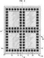
- FIGS. 1-3 depict an example of a microelectronic element 100, e.g., a device wafer embodying active circuit elements, has a major surface 102 and a second surface 104 remote from major surface 102.
- a dielectric layer 120 and at least one bond pad 110 are exposed at major surface 102.
- Dielectric layer 120 is preferably comprised of a material that may be compressible to absorb any dimensional tolerances with regard to bond pads 110 above major surface 102.
- the height of at least one of bond pads 110 above major surface 102 may differ from the height of dielectric layer 120 above major surface 102, as shown more clearly in FIG. 2 .
- Microelectronic element 100 may be a wafer or a semiconductor chip having a plurality of active circuit elements, or a portion of a wafer containing a plurality of semiconductor chips. In another example, microelectronic element 100 may be reconstituted wafer or panel including a plurality of active chips arranged in an array and held together for processing simultaneously. Shown more clearly in FIG. 3 is a portion of a wafer containing four semiconductor chips 111 attached together at dicing lanes 112. Bond pads 110 may be arranged in an array including, for example, being arranged in one or more rows. For example, bond pads 110 may be disposed in rows adjacent the dicing lanes along the periphery 125 of each chip. Dielectric layer 120 may be disposed within the peripheral bond pads to overlie a central region of major surface 102.
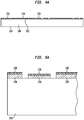
- FIGS. 4-6 depict microelectronic element 100, not falling within the scope of the claimed invention, having a metal layer 130 overlying bond pads 110 and dielectric layer 120.
- the metal layer 130 can be relatively thin.
- a joining metal such as a reflowable metal layer 150 can be deposited to overlie metal layer 130.
- the metal layer 130 may include tin, solder, indium, gold, or any combination thereof.
- the metal layer 130 is a reflowable metal
- the underlying metal layer 130 can be wettable by the reflowable metal.
- the wettable metal layer 130 can include a layer of copper or copper alloy, aluminum or aluminum alloy, or a combination thereof.
- Such layer or layers can form a base structure of the metal layer 130.
- Such metal layer 130 may further include a layer of nickel overlying the base structure.
- the metal layer 130 may include such layer of nickel, and a layer of gold overlying the nickel layer.
- Metal layer 130 may not directly overlie major surface 102, and a gap 140 may exist in metal layer 130 between bond pad 110 and dielectric layer 120. A gap 140 may exist between each adjacent pair of bond pads 110 and dielectric layers 120. Each individual bond pad 110 and dielectric layer can be isolated on major surface 102.
- FIGS. 10 and 11 depict microelectronic element 100 being assembled with another element 200, typically to form a wafer-level assembly 300, or other assembly 300 including one or more active chips bonded and electrically interconnected with another active chip or other element.
- Element 200 may be substantially similar to microelectronic element 100 having active circuit elements, or may be a passive element or wafer having passive circuit elements.
- Element 200 typically is made of semiconductor material and typically is a semiconductor device wafer embodying active circuit elements, e.g., transistors, diodes, etc. However, element 200 can be a passive or essentially blank semiconductor wafer or other element which can include a base of glass or ceramic material, or other material having a CTE less than 10 ppm/°C. Element 200 may be as shown in FIGS.
- Element 200 has a major surface 202, a second surface 204 remote from major surface 202, and a dielectric layer 220 exposed at major surface 202.
- element 200 may be a microelectronic element containing a plurality of active circuit elements and may include at least one bond pad 210.
- a thin metal layer 230 overlies dielectric layer 220, as shown in FIG. 5A , and also overlies bond pads 210, as shown in FIG. 10 .
- a reflowable metal layer 250 is deposited to overlie metal layer 230.
- the metal layers 230 and 250 can be as described above for metal layers 130, 150 of the microelectronic element or wafer 100.
- a gap 240 may exist in metal layer 250 between bond pad 210 and dielectric layer 220, or in the case of a passive element, in between adjacent portions of dielectric layer 220.
- elements 100 and 200 are provided with at least element 100 being an active microelectronic element.
- Metal layers 150 and 250 are deposited over the respective elements. This step may be carried out in different ways. For example, a metal may be deposited over substantially the entire major surface 102, 104 of the respective element 100, 200, covering any bond pads 110, 210 and/or dielectric layers 120, 220 disposed thereon. A portion of the metal may then be removed such that the metal extends to a predetermined height above major surface 102, 104. The metal directly overlying major surface 102, 104 may then be removed at gap 140, 240 between bond pads 110, 210 and dielectric layers 120, 220. Further, each step of depositing the respective metal layer 150, 250 may include depositing a first stage including a metal which can include copper or aluminum, for example.
- bond pads 110 of element 100 are juxtaposed with bond pads 210 of element 200, as shown in FIG. 10 .
- bond pads 110 and 210 may comprise a plurality of electrically isolated metal elements that are eventually disposed on their respective major surfaces 102, 202 between dielectric layers 120, 220.
- Metal layers 130, 230 above the dielectric material (or the isolated metal elements) may be electrically isolated from internal elements within the respective element 100, 200 or, alternatively, may be usable for connection to a source of power or ground.
- elements 100 and 200 are then joined to one another with metal layer 150 joined to metal layer 250 to form assembly 300, such as by heating the reflow metals to a temperature that causes them to melt and fuse together.
- At least one of metal layers 150, 250 is heated to a temperature between about 50 and 300 °C.
- joining of metal layers of solder, tin, indium or gold, or combination thereof can usually be performed at temperatures below 300 °C.
- At least one of metal layers 150 and 250 may include at least a portion which is exothermic and thermally-activated through application of heat, and the step of joining may include heating the at least a portion of the exothermic metal layer to thermally activate such layer. Any dimensional tolerances are preferably accounted for and absorbed by at least one of dielectric layers 120, 220 being compressible.
- Gaps 140 and 240 can be large enough to provide a relief volume sufficient to compensate for a sum of the total variation in co-planarity of the top surfaces of metal layers 150 and 250 overlying the respective bond pads 110 and 210 and dielectric layers 120 and 220. As can be seen in FIG. 11 , certain portions of the combined metal layers 150 and 250 may bulge out into gaps 140, 240 as seen at areas 152. Alternatively, portions of such combined metal layers can appear to have concave surfaces adjacent gaps 140, 240 as shown at areas 154. It is also possible that portions of the combined metal layers 150 and 250 have essentially straight and vertical edges as seen at 156. Thus, the joining of elements 100 and 200 is aided by the reflowable metal layers 150 and 250 being able to electrically connect while potentially overflowing into gaps 140, 240 due to any dimensional differentiation related to elements 100 and 200.
- metal layers 150 and 250 may comprise copper instead of a reflowable metal and in examples which do not fall within the scope of the claimed invention one or both metal layers 130, 230 in some cases may be omitted.
- Joining such layers includes applying heat and pressure between elements 100, 200 such that the copper layers fuse together.
- a layer of gold may overlie at least one of metal layers 150 and 250, which may be heated to a temperature at which the gold diffuses into the copper at the joining interface between the metal layers 150, 250.
- the step of depositing metal layers 150, 250 includes depositing a base metal and a layer of gold overlying the base metal. Heat and pressure are then applied to the elements until metal layers 150, 250 fuse together.
- assembly 300 may be severed along dicing lanes, one such lane being denoted by line 301, into individual microelectronic assemblies or units.
- each unit includes an active chip, i.e., a chip embodying active circuit elements, and a corresponding portion of the element 200, which may or may not include another active chip.
- Assembly 300 may be further constructed as shown in FIG. 12 such that at least one of elements 100 and 200 includes a through via 302 electrically connected with a bond pad and extending through the thickness of such element.
- a through via 302 extends through element 100 and provides an electrically conductive element therein which is electrically connected to a bond pad 110.
- an electrically conductive through via 302 can extend through element 200 and be electrically connected with bond pad 210.
- An electrically conductive through via 303 may extend through both elements 100 and 200 and be electrically connected with a bond pad 110 of element 100 and a bond pad 210 of element 200, as shown in FIG. 13 .
- metal layers 150, 250 are present prior to joining elements 100 and 200. This construction is shown in FIG. 14 , where element 1100 includes metal layer 1150 overlying metal layer 1130, and element 1200 includes as its top layer only metal layer 1230, with no other metal layer overlying same.
- an element 2200 can be an interposer, cover wafer or blank wafer, which has no exposed bond pads.
- Elements 2100, 2200 each include a dielectric layer 2120, 2220, respectively, and a metal layer 2130, 2230 overlying dielectric layers 2120, 2220, respectively.
- Bond pads 2110 overlying major surface 2102 of element 2100 are adjacent an exposed portion of major surface 2202 of element 2200.
- Metal layers 2130, 2230 which may only overlie dielectric layers 2120, 2220 and not bond pads 2110, can be electrically interconnected through the joined reflowable metal layers 2150, 2250.
- the metal layers 130 ( FIG. 11 ), or metal layers 2130 ( FIG. 15 ) on respective wafers or elements can be electrically isolated from one another, and from the wafer or element on which they are provided both before and after bonding the wafers or elements together.
- some or all of the metal layers 130 or 230 on a wafer or element can be usable for connection to a source of power or ground.
- a metal layer 130 or 230 on a wafer can extend onto or be electrically connected with ground bond pads of the same wafer which provide ground connections to the chips of such wafer.
- the metal layer 130, or 230 on a wafer can extend onto or be electrically connected with power bond pads of the same wafer which provide power source connections to the chips of such wafer.
- some portions of the metal layers 130, 230 of each microelectronic assembly can extend onto or be electrically connected with ground bond pads, and other portions of the metal layers 130, 230 of each microelectronic assembly can extend onto or be electrically connected with power bond pads.
- the metal layer of each chip of both wafers, e.g., metal layers 130, 230, and the reflowable metal 150 ( FIG. 11 ) between them in each assembly would be available for connection to a ground terminal or to a power terminal of a microelectronic assembly in which the chips are incorporated.
- the techniques provided herein typically can compensate for nonplanarity in bonding interface.
- the joining or reflowable metal layers 150, 250 can have a thickness of 1 micron on the metal layers 130, 230 and the bond pads 110, 210 of the respective wafers.
- the nominal joined thickness of the metal layer 150 e.g., FIG. 11
- the techniques provided herein can compensate for a total variation in the planarity of the bonding interface across the entire dimensions of the wafers to an extent greater than 0.5 microns.
- the techniques herein can compensate for even greater nonplanarity, such as 3 microns.
- a system 900 includes a structure 906 as described above in conjunction with other electronic components 908 and 910.
- component 908 is a semiconductor chip whereas component 910 is a display screen, but any other components can be used.
- the structure 906 as described above may be, for example, a composite chip as discussed above or a structure incorporating plural chips. In a further variant, both may be provided, and any number of such structures may be used.
- Structure 906 and components 908 and 910 are mounted in a common housing 901, schematically depicted in broken lines, and are electrically interconnected with one another as necessary to form the desired circuit.
- the system includes a circuit panel 902 such as a flexible printed circuit board, and the circuit panel includes numerous conductors 904, of which only one is depicted in FIG. 16 , interconnecting the components with one another.
- the housing 901 is depicted as a portable housing of the type usable, for example, in a cellular telephone or personal digital assistant, and screen 910 is exposed at the surface of the housing.
- structure 908 includes a light-sensitive element such as an imaging chip
- a lens 911 or other optical device also may be provided for routing light to the structure.
- the simplified system shown in FIG. 16 is merely exemplary; other systems, including systems commonly regarded as fixed structures, such as desktop computers, routers and the like can be made using the structures discussed above.
- the present invention enjoys wide industrial applicability including, but not limited to, microelectronic assemblies and methods of forming same.
Landscapes
- Internal Circuitry In Semiconductor Integrated Circuit Devices (AREA)
- Wire Bonding (AREA)
- Engineering & Computer Science (AREA)
- Physics & Mathematics (AREA)
- Condensed Matter Physics & Semiconductors (AREA)
- General Physics & Mathematics (AREA)
- Microelectronics & Electronic Packaging (AREA)
- Manufacturing & Machinery (AREA)
Applications Claiming Priority (2)
| Application Number | Priority Date | Filing Date | Title |
|---|---|---|---|
| US201061424906P | 2010-12-20 | 2010-12-20 | |
| PCT/US2011/030871 WO2012087364A1 (en) | 2010-12-20 | 2011-04-01 | Simultaneous wafer bonding and interconnect joining |
Publications (2)
| Publication Number | Publication Date |
|---|---|
| EP2656383A1 EP2656383A1 (en) | 2013-10-30 |
| EP2656383B1 true EP2656383B1 (en) | 2021-11-03 |
Family
ID=46233332
Family Applications (1)
| Application Number | Title | Priority Date | Filing Date |
|---|---|---|---|
| EP11713628.3A Active EP2656383B1 (en) | 2010-12-20 | 2011-04-01 | Microelectronic assembly |
Country Status (7)
| Country | Link |
|---|---|
| US (2) | US8486758B2 (https=) |
| EP (1) | EP2656383B1 (https=) |
| JP (1) | JP5881734B2 (https=) |
| KR (2) | KR101091551B1 (https=) |
| CN (1) | CN103370784B (https=) |
| TW (1) | TWI406383B (https=) |
| WO (1) | WO2012087364A1 (https=) |
Families Citing this family (19)
| Publication number | Priority date | Publication date | Assignee | Title |
|---|---|---|---|---|
| US9237648B2 (en) | 2013-02-25 | 2016-01-12 | Invensas Corporation | Carrier-less silicon interposer |
| US9691693B2 (en) | 2013-12-04 | 2017-06-27 | Invensas Corporation | Carrier-less silicon interposer using photo patterned polymer as substrate |
| CN104900543B (zh) * | 2014-03-06 | 2018-02-06 | 中芯国际集成电路制造(上海)有限公司 | 一种半导体器件及其制备方法 |
| US9704841B2 (en) * | 2014-03-26 | 2017-07-11 | United Microelectronics Corp. | Method of packaging stacked dies on wafer using flip-chip bonding |
| CN105023877B (zh) | 2014-04-28 | 2019-12-24 | 联华电子股份有限公司 | 半导体晶片、封装结构与其制作方法 |
| KR102258743B1 (ko) | 2014-04-30 | 2021-06-02 | 삼성전자주식회사 | 반도체 패키지의 제조 방법, 이에 의해 형성된 반도체 패키지 및 이를 포함하는 반도체 장치 |
| US9437536B1 (en) | 2015-05-08 | 2016-09-06 | Invensas Corporation | Reversed build-up substrate for 2.5D |
| TWI645479B (zh) | 2015-05-13 | 2018-12-21 | 財團法人工業技術研究院 | 貼合結構、其製造方法及晶粒結構 |
| US10211160B2 (en) | 2015-09-08 | 2019-02-19 | Invensas Corporation | Microelectronic assembly with redistribution structure formed on carrier |
| US9666560B1 (en) | 2015-11-25 | 2017-05-30 | Invensas Corporation | Multi-chip microelectronic assembly with built-up fine-patterned circuit structure |
| US9691747B1 (en) | 2015-12-21 | 2017-06-27 | International Business Machines Corporation | Manufacture of wafer—panel die package assembly technology |
| TWI607587B (zh) * | 2016-09-13 | 2017-12-01 | 台灣琭旦股份有限公司 | 固晶穩固製程 |
| US10283445B2 (en) | 2016-10-26 | 2019-05-07 | Invensas Corporation | Bonding of laminates with electrical interconnects |
| CN111115555B (zh) * | 2019-12-20 | 2023-08-29 | 北京航天控制仪器研究所 | 一种用于mems晶圆级共晶键合封装的硅槽结构及制备方法 |
| CN111179612B (zh) * | 2019-12-27 | 2021-09-07 | 讯飞智元信息科技有限公司 | 交叉口车道功能生成方法、装置和设备 |
| US11270963B2 (en) | 2020-01-14 | 2022-03-08 | Sandisk Technologies Llc | Bonding pads including interfacial electromigration barrier layers and methods of making the same |
| US20210296281A1 (en) * | 2020-03-20 | 2021-09-23 | Integrated Silicon Solution Inc. | Wafer-bonding structure and method of forming thereof |
| CN112103261A (zh) * | 2020-11-10 | 2020-12-18 | 浙江里阳半导体有限公司 | 半导体封装结构及其制作方法 |
| US12598962B2 (en) | 2023-03-14 | 2026-04-07 | Adeia Semiconductor Bonding Technologies Inc. | System and method for bonding transparent conductor substrates |
Citations (2)
| Publication number | Priority date | Publication date | Assignee | Title |
|---|---|---|---|---|
| US5726500A (en) * | 1994-04-08 | 1998-03-10 | Thomson-Csf | Semiconductor hybrid component |
| US20030183945A1 (en) * | 1999-06-28 | 2003-10-02 | Park Sang Wook | Chip size stack package and method of fabricating the same |
Family Cites Families (30)
| Publication number | Priority date | Publication date | Assignee | Title |
|---|---|---|---|---|
| JPS5965457A (ja) * | 1982-10-05 | 1984-04-13 | Mitsubishi Electric Corp | 半導体装置 |
| JPH07112041B2 (ja) * | 1986-12-03 | 1995-11-29 | シャープ株式会社 | 半導体装置の製造方法 |
| JPH0750316A (ja) | 1993-08-09 | 1995-02-21 | Fujitsu Ltd | 電子回路のフリップチップ接合方法 |
| WO1997011492A1 (en) | 1995-09-20 | 1997-03-27 | Hitachi, Ltd. | Semiconductor device and its manufacture |
| KR100438256B1 (ko) * | 1995-12-18 | 2004-08-25 | 마츠시타 덴끼 산교 가부시키가이샤 | 반도체장치 및 그 제조방법 |
| JP2007201512A (ja) * | 1996-12-02 | 2007-08-09 | Toshiba Corp | マルチチップ半導体装置、マルチチップ半導体装置用チップおよびその形成方法 |
| JPH11112150A (ja) | 1997-09-30 | 1999-04-23 | Hokuriku Electric Ind Co Ltd | 多層基板とその製造方法 |
| JP3420076B2 (ja) * | 1998-08-31 | 2003-06-23 | 新光電気工業株式会社 | フリップチップ実装基板の製造方法及びフリップチップ実装基板及びフリップチップ実装構造 |
| JP4009380B2 (ja) * | 1999-02-18 | 2007-11-14 | ローム株式会社 | 半導体チップの製造方法 |
| JP3342845B2 (ja) * | 1999-02-26 | 2002-11-11 | ローム株式会社 | 半導体装置 |
| KR100396551B1 (ko) | 2001-02-03 | 2003-09-03 | 삼성전자주식회사 | 웨이퍼 레벨 허메틱 실링 방법 |
| US6975016B2 (en) * | 2002-02-06 | 2005-12-13 | Intel Corporation | Wafer bonding using a flexible bladder press and thinned wafers for three-dimensional (3D) wafer-to-wafer vertical stack integration, and application thereof |
| DE10215654A1 (de) | 2002-04-09 | 2003-11-06 | Infineon Technologies Ag | Elektronisches Bauteil mit mindestens einem Halbleiterchip und Flip-Chip-Kontakten sowie Verfahren zu seiner Herstellung |
| US6962835B2 (en) | 2003-02-07 | 2005-11-08 | Ziptronix, Inc. | Method for room temperature metal direct bonding |
| US20050110131A1 (en) | 2003-11-24 | 2005-05-26 | Lee Kevin J. | Vertical wafer stacking using an interposer |
| KR20060011483A (ko) | 2004-07-30 | 2006-02-03 | 기아자동차주식회사 | 차량의 쿨박스 동작 장치 및 방법 |
| KR100601483B1 (ko) | 2004-12-06 | 2006-07-18 | 삼성전기주식회사 | 비아포스트에 의해 층간 전도성이 부여된 병렬적 다층인쇄회로기판 및 그 제조 방법 |
| US20060292823A1 (en) * | 2005-06-28 | 2006-12-28 | Shriram Ramanathan | Method and apparatus for bonding wafers |
| US20070080441A1 (en) | 2005-08-18 | 2007-04-12 | Scott Kirkman | Thermal expansion compensation graded IC package |
| JP2008098257A (ja) | 2006-10-09 | 2008-04-24 | Sumitomo Electric Ind Ltd | 接続構造 |
| JP4345808B2 (ja) | 2006-12-15 | 2009-10-14 | エルピーダメモリ株式会社 | 半導体装置の製造方法 |
| EP2135280A2 (en) | 2007-03-05 | 2009-12-23 | Tessera, Inc. | Chips having rear contacts connected by through vias to front contacts |
| SG152101A1 (en) | 2007-11-06 | 2009-05-29 | Agency Science Tech & Res | An interconnect structure and a method of fabricating the same |
| US7872357B2 (en) * | 2008-03-05 | 2011-01-18 | Taiwan Semiconductor Manufacturing Company, Ltd. | Protection for bonding pads and methods of formation |
| KR20090106828A (ko) | 2008-04-07 | 2009-10-12 | 삼성전자주식회사 | 웨이퍼 본딩 방법 및 그 방법에 의해 본딩된 웨이퍼 구조체 |
| KR100945800B1 (ko) | 2008-12-09 | 2010-03-05 | 김영혜 | 이종 접합 웨이퍼 제조방법 |
| US8153905B2 (en) * | 2009-02-27 | 2012-04-10 | Ibiden Co., Ltd. | Method for manufacturing printed wiring board and printed wiring board |
| JP5697898B2 (ja) * | 2009-10-09 | 2015-04-08 | ピーエスフォー ルクスコ エスエイアールエルPS4 Luxco S.a.r.l. | 半導体装置及びその製造方法 |
| US8796135B2 (en) | 2010-07-23 | 2014-08-05 | Tessera, Inc. | Microelectronic elements with rear contacts connected with via first or via middle structures |
| US8791575B2 (en) | 2010-07-23 | 2014-07-29 | Tessera, Inc. | Microelectronic elements having metallic pads overlying vias |
-
2011
- 2011-03-31 US US13/076,969 patent/US8486758B2/en active Active
- 2011-04-01 JP JP2013546103A patent/JP5881734B2/ja active Active
- 2011-04-01 WO PCT/US2011/030871 patent/WO2012087364A1/en not_active Ceased
- 2011-04-01 CN CN201180067909.3A patent/CN103370784B/zh active Active
- 2011-04-01 EP EP11713628.3A patent/EP2656383B1/en active Active
- 2011-04-07 KR KR1020110032044A patent/KR101091551B1/ko not_active Expired - Fee Related
- 2011-06-24 KR KR1020110061826A patent/KR20120069515A/ko not_active Withdrawn
- 2011-12-20 TW TW100147552A patent/TWI406383B/zh active
-
2013
- 2013-07-11 US US13/939,725 patent/US8709913B2/en active Active
Patent Citations (2)
| Publication number | Priority date | Publication date | Assignee | Title |
|---|---|---|---|---|
| US5726500A (en) * | 1994-04-08 | 1998-03-10 | Thomson-Csf | Semiconductor hybrid component |
| US20030183945A1 (en) * | 1999-06-28 | 2003-10-02 | Park Sang Wook | Chip size stack package and method of fabricating the same |
Also Published As
| Publication number | Publication date |
|---|---|
| US20130341804A1 (en) | 2013-12-26 |
| US8709913B2 (en) | 2014-04-29 |
| TW201236131A (en) | 2012-09-01 |
| US20120153488A1 (en) | 2012-06-21 |
| EP2656383A1 (en) | 2013-10-30 |
| TWI406383B (zh) | 2013-08-21 |
| US8486758B2 (en) | 2013-07-16 |
| CN103370784A (zh) | 2013-10-23 |
| CN103370784B (zh) | 2016-08-24 |
| KR101091551B1 (ko) | 2011-12-13 |
| KR20120069515A (ko) | 2012-06-28 |
| WO2012087364A1 (en) | 2012-06-28 |
| JP2014500630A (ja) | 2014-01-09 |
| JP5881734B2 (ja) | 2016-03-09 |
Similar Documents
| Publication | Publication Date | Title |
|---|---|---|
| EP2656383B1 (en) | Microelectronic assembly | |
| CN103329266B (zh) | 具有连接有源芯片的插板的堆叠微电子组件 | |
| US9368476B2 (en) | Stacked microelectronic assembly with TSVs formed in stages with plural active chips | |
| US10396114B2 (en) | Method of fabricating low CTE interposer without TSV structure | |
| US8951845B2 (en) | Methods of fabricating a flip chip package for dram with two underfill materials | |
| US9237648B2 (en) | Carrier-less silicon interposer | |
| US9859234B2 (en) | Methods and structures to repair device warpage |
Legal Events
| Date | Code | Title | Description |
|---|---|---|---|
| PUAI | Public reference made under article 153(3) epc to a published international application that has entered the european phase |
Free format text: ORIGINAL CODE: 0009012 |
|
| 17P | Request for examination filed |
Effective date: 20130708 |
|
| AK | Designated contracting states |
Kind code of ref document: A1 Designated state(s): AL AT BE BG CH CY CZ DE DK EE ES FI FR GB GR HR HU IE IS IT LI LT LU LV MC MK MT NL NO PL PT RO RS SE SI SK SM TR |
|
| DAX | Request for extension of the european patent (deleted) | ||
| STAA | Information on the status of an ep patent application or granted ep patent |
Free format text: STATUS: EXAMINATION IS IN PROGRESS |
|
| 17Q | First examination report despatched |
Effective date: 20190128 |
|
| GRAP | Despatch of communication of intention to grant a patent |
Free format text: ORIGINAL CODE: EPIDOSNIGR1 |
|
| STAA | Information on the status of an ep patent application or granted ep patent |
Free format text: STATUS: GRANT OF PATENT IS INTENDED |
|
| INTG | Intention to grant announced |
Effective date: 20210223 |
|
| GRAJ | Information related to disapproval of communication of intention to grant by the applicant or resumption of examination proceedings by the epo deleted |
Free format text: ORIGINAL CODE: EPIDOSDIGR1 |
|
| STAA | Information on the status of an ep patent application or granted ep patent |
Free format text: STATUS: EXAMINATION IS IN PROGRESS |
|
| GRAP | Despatch of communication of intention to grant a patent |
Free format text: ORIGINAL CODE: EPIDOSNIGR1 |
|
| STAA | Information on the status of an ep patent application or granted ep patent |
Free format text: STATUS: GRANT OF PATENT IS INTENDED |
|
| INTC | Intention to grant announced (deleted) | ||
| INTG | Intention to grant announced |
Effective date: 20210716 |
|
| GRAS | Grant fee paid |
Free format text: ORIGINAL CODE: EPIDOSNIGR3 |
|
| GRAA | (expected) grant |
Free format text: ORIGINAL CODE: 0009210 |
|
| STAA | Information on the status of an ep patent application or granted ep patent |
Free format text: STATUS: THE PATENT HAS BEEN GRANTED |
|
| AK | Designated contracting states |
Kind code of ref document: B1 Designated state(s): AL AT BE BG CH CY CZ DE DK EE ES FI FR GB GR HR HU IE IS IT LI LT LU LV MC MK MT NL NO PL PT RO RS SE SI SK SM TR |
|
| REG | Reference to a national code |
Ref country code: GB Ref legal event code: FG4D |
|
| REG | Reference to a national code |
Ref country code: AT Ref legal event code: REF Ref document number: 1444740 Country of ref document: AT Kind code of ref document: T Effective date: 20211115 Ref country code: CH Ref legal event code: EP |
|
| REG | Reference to a national code |
Ref country code: IE Ref legal event code: FG4D |
|
| REG | Reference to a national code |
Ref country code: DE Ref legal event code: R096 Ref document number: 602011072037 Country of ref document: DE |
|
| REG | Reference to a national code |
Ref country code: NL Ref legal event code: FP |
|
| REG | Reference to a national code |
Ref country code: LT Ref legal event code: MG9D |
|
| REG | Reference to a national code |
Ref country code: AT Ref legal event code: MK05 Ref document number: 1444740 Country of ref document: AT Kind code of ref document: T Effective date: 20211103 |
|
| PG25 | Lapsed in a contracting state [announced via postgrant information from national office to epo] |
Ref country code: RS Free format text: LAPSE BECAUSE OF FAILURE TO SUBMIT A TRANSLATION OF THE DESCRIPTION OR TO PAY THE FEE WITHIN THE PRESCRIBED TIME-LIMIT Effective date: 20211103 Ref country code: LT Free format text: LAPSE BECAUSE OF FAILURE TO SUBMIT A TRANSLATION OF THE DESCRIPTION OR TO PAY THE FEE WITHIN THE PRESCRIBED TIME-LIMIT Effective date: 20211103 Ref country code: FI Free format text: LAPSE BECAUSE OF FAILURE TO SUBMIT A TRANSLATION OF THE DESCRIPTION OR TO PAY THE FEE WITHIN THE PRESCRIBED TIME-LIMIT Effective date: 20211103 Ref country code: BG Free format text: LAPSE BECAUSE OF FAILURE TO SUBMIT A TRANSLATION OF THE DESCRIPTION OR TO PAY THE FEE WITHIN THE PRESCRIBED TIME-LIMIT Effective date: 20220203 Ref country code: AT Free format text: LAPSE BECAUSE OF FAILURE TO SUBMIT A TRANSLATION OF THE DESCRIPTION OR TO PAY THE FEE WITHIN THE PRESCRIBED TIME-LIMIT Effective date: 20211103 |
|
| PG25 | Lapsed in a contracting state [announced via postgrant information from national office to epo] |
Ref country code: IS Free format text: LAPSE BECAUSE OF FAILURE TO SUBMIT A TRANSLATION OF THE DESCRIPTION OR TO PAY THE FEE WITHIN THE PRESCRIBED TIME-LIMIT Effective date: 20220303 Ref country code: SE Free format text: LAPSE BECAUSE OF FAILURE TO SUBMIT A TRANSLATION OF THE DESCRIPTION OR TO PAY THE FEE WITHIN THE PRESCRIBED TIME-LIMIT Effective date: 20211103 Ref country code: PT Free format text: LAPSE BECAUSE OF FAILURE TO SUBMIT A TRANSLATION OF THE DESCRIPTION OR TO PAY THE FEE WITHIN THE PRESCRIBED TIME-LIMIT Effective date: 20220303 Ref country code: PL Free format text: LAPSE BECAUSE OF FAILURE TO SUBMIT A TRANSLATION OF THE DESCRIPTION OR TO PAY THE FEE WITHIN THE PRESCRIBED TIME-LIMIT Effective date: 20211103 Ref country code: NO Free format text: LAPSE BECAUSE OF FAILURE TO SUBMIT A TRANSLATION OF THE DESCRIPTION OR TO PAY THE FEE WITHIN THE PRESCRIBED TIME-LIMIT Effective date: 20220203 Ref country code: LV Free format text: LAPSE BECAUSE OF FAILURE TO SUBMIT A TRANSLATION OF THE DESCRIPTION OR TO PAY THE FEE WITHIN THE PRESCRIBED TIME-LIMIT Effective date: 20211103 Ref country code: HR Free format text: LAPSE BECAUSE OF FAILURE TO SUBMIT A TRANSLATION OF THE DESCRIPTION OR TO PAY THE FEE WITHIN THE PRESCRIBED TIME-LIMIT Effective date: 20211103 Ref country code: GR Free format text: LAPSE BECAUSE OF FAILURE TO SUBMIT A TRANSLATION OF THE DESCRIPTION OR TO PAY THE FEE WITHIN THE PRESCRIBED TIME-LIMIT Effective date: 20220204 Ref country code: ES Free format text: LAPSE BECAUSE OF FAILURE TO SUBMIT A TRANSLATION OF THE DESCRIPTION OR TO PAY THE FEE WITHIN THE PRESCRIBED TIME-LIMIT Effective date: 20211103 |
|
| PG25 | Lapsed in a contracting state [announced via postgrant information from national office to epo] |
Ref country code: SM Free format text: LAPSE BECAUSE OF FAILURE TO SUBMIT A TRANSLATION OF THE DESCRIPTION OR TO PAY THE FEE WITHIN THE PRESCRIBED TIME-LIMIT Effective date: 20211103 Ref country code: SK Free format text: LAPSE BECAUSE OF FAILURE TO SUBMIT A TRANSLATION OF THE DESCRIPTION OR TO PAY THE FEE WITHIN THE PRESCRIBED TIME-LIMIT Effective date: 20211103 Ref country code: RO Free format text: LAPSE BECAUSE OF FAILURE TO SUBMIT A TRANSLATION OF THE DESCRIPTION OR TO PAY THE FEE WITHIN THE PRESCRIBED TIME-LIMIT Effective date: 20211103 Ref country code: EE Free format text: LAPSE BECAUSE OF FAILURE TO SUBMIT A TRANSLATION OF THE DESCRIPTION OR TO PAY THE FEE WITHIN THE PRESCRIBED TIME-LIMIT Effective date: 20211103 Ref country code: DK Free format text: LAPSE BECAUSE OF FAILURE TO SUBMIT A TRANSLATION OF THE DESCRIPTION OR TO PAY THE FEE WITHIN THE PRESCRIBED TIME-LIMIT Effective date: 20211103 Ref country code: CZ Free format text: LAPSE BECAUSE OF FAILURE TO SUBMIT A TRANSLATION OF THE DESCRIPTION OR TO PAY THE FEE WITHIN THE PRESCRIBED TIME-LIMIT Effective date: 20211103 |
|
| REG | Reference to a national code |
Ref country code: DE Ref legal event code: R097 Ref document number: 602011072037 Country of ref document: DE |
|
| PLBE | No opposition filed within time limit |
Free format text: ORIGINAL CODE: 0009261 |
|
| STAA | Information on the status of an ep patent application or granted ep patent |
Free format text: STATUS: NO OPPOSITION FILED WITHIN TIME LIMIT |
|
| 26N | No opposition filed |
Effective date: 20220804 |
|
| PG25 | Lapsed in a contracting state [announced via postgrant information from national office to epo] |
Ref country code: AL Free format text: LAPSE BECAUSE OF FAILURE TO SUBMIT A TRANSLATION OF THE DESCRIPTION OR TO PAY THE FEE WITHIN THE PRESCRIBED TIME-LIMIT Effective date: 20211103 |
|
| PG25 | Lapsed in a contracting state [announced via postgrant information from national office to epo] |
Ref country code: SI Free format text: LAPSE BECAUSE OF FAILURE TO SUBMIT A TRANSLATION OF THE DESCRIPTION OR TO PAY THE FEE WITHIN THE PRESCRIBED TIME-LIMIT Effective date: 20211103 |
|
| REG | Reference to a national code |
Ref country code: CH Ref legal event code: PL |
|
| GBPC | Gb: european patent ceased through non-payment of renewal fee |
Effective date: 20220401 |
|
| REG | Reference to a national code |
Ref country code: BE Ref legal event code: MM Effective date: 20220430 |
|
| PG25 | Lapsed in a contracting state [announced via postgrant information from national office to epo] |
Ref country code: MC Free format text: LAPSE BECAUSE OF FAILURE TO SUBMIT A TRANSLATION OF THE DESCRIPTION OR TO PAY THE FEE WITHIN THE PRESCRIBED TIME-LIMIT Effective date: 20211103 Ref country code: LU Free format text: LAPSE BECAUSE OF NON-PAYMENT OF DUE FEES Effective date: 20220401 Ref country code: LI Free format text: LAPSE BECAUSE OF NON-PAYMENT OF DUE FEES Effective date: 20220430 Ref country code: GB Free format text: LAPSE BECAUSE OF NON-PAYMENT OF DUE FEES Effective date: 20220401 Ref country code: FR Free format text: LAPSE BECAUSE OF NON-PAYMENT OF DUE FEES Effective date: 20220430 Ref country code: CH Free format text: LAPSE BECAUSE OF NON-PAYMENT OF DUE FEES Effective date: 20220430 |
|
| PG25 | Lapsed in a contracting state [announced via postgrant information from national office to epo] |
Ref country code: BE Free format text: LAPSE BECAUSE OF NON-PAYMENT OF DUE FEES Effective date: 20220430 |
|
| PG25 | Lapsed in a contracting state [announced via postgrant information from national office to epo] |
Ref country code: IE Free format text: LAPSE BECAUSE OF NON-PAYMENT OF DUE FEES Effective date: 20220401 |
|
| PG25 | Lapsed in a contracting state [announced via postgrant information from national office to epo] |
Ref country code: IT Free format text: LAPSE BECAUSE OF FAILURE TO SUBMIT A TRANSLATION OF THE DESCRIPTION OR TO PAY THE FEE WITHIN THE PRESCRIBED TIME-LIMIT Effective date: 20211103 |
|
| P01 | Opt-out of the competence of the unified patent court (upc) registered |
Effective date: 20230524 |
|
| PG25 | Lapsed in a contracting state [announced via postgrant information from national office to epo] |
Ref country code: HU Free format text: LAPSE BECAUSE OF FAILURE TO SUBMIT A TRANSLATION OF THE DESCRIPTION OR TO PAY THE FEE WITHIN THE PRESCRIBED TIME-LIMIT; INVALID AB INITIO Effective date: 20110401 |
|
| PG25 | Lapsed in a contracting state [announced via postgrant information from national office to epo] |
Ref country code: MK Free format text: LAPSE BECAUSE OF FAILURE TO SUBMIT A TRANSLATION OF THE DESCRIPTION OR TO PAY THE FEE WITHIN THE PRESCRIBED TIME-LIMIT Effective date: 20211103 Ref country code: CY Free format text: LAPSE BECAUSE OF FAILURE TO SUBMIT A TRANSLATION OF THE DESCRIPTION OR TO PAY THE FEE WITHIN THE PRESCRIBED TIME-LIMIT Effective date: 20211103 |
|
| PG25 | Lapsed in a contracting state [announced via postgrant information from national office to epo] |
Ref country code: TR Free format text: LAPSE BECAUSE OF FAILURE TO SUBMIT A TRANSLATION OF THE DESCRIPTION OR TO PAY THE FEE WITHIN THE PRESCRIBED TIME-LIMIT Effective date: 20211103 |
|
| P02 | Opt-out of the competence of the unified patent court (upc) changed |
Free format text: CASE NUMBER: APP_46435/2024 Effective date: 20240809 |
|
| PG25 | Lapsed in a contracting state [announced via postgrant information from national office to epo] |
Ref country code: MT Free format text: LAPSE BECAUSE OF FAILURE TO SUBMIT A TRANSLATION OF THE DESCRIPTION OR TO PAY THE FEE WITHIN THE PRESCRIBED TIME-LIMIT Effective date: 20211103 |
|
| PGFP | Annual fee paid to national office [announced via postgrant information from national office to epo] |
Ref country code: NL Payment date: 20250424 Year of fee payment: 15 |
|
| PGFP | Annual fee paid to national office [announced via postgrant information from national office to epo] |
Ref country code: DE Payment date: 20250428 Year of fee payment: 15 |
|
| REG | Reference to a national code |
Ref country code: DE Ref legal event code: R079 Ref document number: 602011072037 Country of ref document: DE Free format text: PREVIOUS MAIN CLASS: H01L0021980000 Ipc: H10W0090240000 |
|
| REG | Reference to a national code |
Ref country code: NL Ref legal event code: HC Owner name: ADEIA SEMICONDUCTOR SOLUTIONS LLC; US Free format text: DETAILS ASSIGNMENT: CHANGE OF OWNER(S), CHANGE OF OWNER(S) NAME; FORMER OWNER NAME: TESSERA LLC Effective date: 20260212 Ref country code: NL Ref legal event code: PD Owner name: TESSERA LLC; US Free format text: DETAILS ASSIGNMENT: CHANGE OF OWNER(S), CHANGE OF LEGAL ENTITY; FORMER OWNER NAME: TESSERA, INC. Effective date: 20260212 |