EP2652207B1 - Schalungselement - Google Patents
Schalungselement Download PDFInfo
- Publication number
- EP2652207B1 EP2652207B1 EP20110797008 EP11797008A EP2652207B1 EP 2652207 B1 EP2652207 B1 EP 2652207B1 EP 20110797008 EP20110797008 EP 20110797008 EP 11797008 A EP11797008 A EP 11797008A EP 2652207 B1 EP2652207 B1 EP 2652207B1
- Authority
- EP
- European Patent Office
- Prior art keywords
- hollow
- formwork element
- body formwork
- pile
- layer
- Prior art date
- Legal status (The legal status is an assumption and is not a legal conclusion. Google has not performed a legal analysis and makes no representation as to the accuracy of the status listed.)
- Not-in-force
Links
Images


Classifications
-
- E—FIXED CONSTRUCTIONS
- E02—HYDRAULIC ENGINEERING; FOUNDATIONS; SOIL SHIFTING
- E02D—FOUNDATIONS; EXCAVATIONS; EMBANKMENTS; UNDERGROUND OR UNDERWATER STRUCTURES
- E02D31/00—Protective arrangements for foundations or foundation structures; Ground foundation measures for protecting the soil or the subsoil water, e.g. preventing or counteracting oil pollution
- E02D31/02—Protective arrangements for foundations or foundation structures; Ground foundation measures for protecting the soil or the subsoil water, e.g. preventing or counteracting oil pollution against ground humidity or ground water
-
- E—FIXED CONSTRUCTIONS
- E02—HYDRAULIC ENGINEERING; FOUNDATIONS; SOIL SHIFTING
- E02D—FOUNDATIONS; EXCAVATIONS; EMBANKMENTS; UNDERGROUND OR UNDERWATER STRUCTURES
- E02D29/00—Independent underground or underwater structures; Retaining walls
- E02D29/16—Arrangement or construction of joints in foundation structures
-
- E—FIXED CONSTRUCTIONS
- E02—HYDRAULIC ENGINEERING; FOUNDATIONS; SOIL SHIFTING
- E02D—FOUNDATIONS; EXCAVATIONS; EMBANKMENTS; UNDERGROUND OR UNDERWATER STRUCTURES
- E02D31/00—Protective arrangements for foundations or foundation structures; Ground foundation measures for protecting the soil or the subsoil water, e.g. preventing or counteracting oil pollution
- E02D31/02—Protective arrangements for foundations or foundation structures; Ground foundation measures for protecting the soil or the subsoil water, e.g. preventing or counteracting oil pollution against ground humidity or ground water
- E02D31/04—Watertight packings for use under hydraulic pressure
Definitions
- the present invention relates to a method for sealing a pile associated with a breakthrough in a geomembrane in the construction sector.
- Bored piles are used, for example, for foundation foundations, especially in soft substrates. For their production, a hole is made with the desired depth and introduced a bored pile in the well or the bored pile immediately driven directly into the ground.
- the substrate When building a concrete structure, the substrate is typically covered with a geomembrane to prevent ingress of water from the subsoil into the structure.
- the bored piles are directly or indirectly connected to the structure, for which the sealing sheet must be pierced. This creates an area in the area of the penetration between the geomembrane and the bored pile, through which moisture from the substrate can enter the building, as can the one out WO 2010/028766 A1 comes out.
- Object of the present invention is therefore to improve a method of the type mentioned in that moisture from the ground is unable to penetrate in the region of the penetration between geomembrane and bored pile.
- the hollow body-shaped formwork element has on the side facing the pile to a contact layer, which has a composite layer of a porous material and / or a sealant.
- FIGS. 1a, 1b and 1c are shown a lateral cross section through a sealed pile according to the inventive method.
- the pile 1 is a pile in the construction area, which is embedded in a substrate 2.
- length, diameter, material, design of the piles can vary.
- the pile is made of materials selected from the group consisting of wood, metal and hardened mineral binders, preferably hardened mineral binders, most preferably concrete.
- Such a pole preferably has a length of 5-25 meters and preferably a diameter of 0.3-2 meters, in particular 0.6-1.2 meters.
- the pile 1 is a bored pile.
- the pile 1 can continue on its the Schott layer 4 facing end support elements 11th have, which, for example, to a wide distribution of the load, respectively anchoring load required.
- the method according to the invention comprises the step 1) of applying a bulkhead layer 4 to the substrate 2.
- the substrate 2 is typically the soil, the substrate may or may not be horizontal, preferably the substrate is substantially horizontal.
- the Schott layer 4 is typically a waterproofing membrane which is suitable for sealing a structure against moisture from the substrate.
- the Schott layer can consist of all materials which ensure sufficient tightness even at high liquid pressures.
- the scotch layer has a high resistance to water pressure, as well as good values in tear propagation and perforation tests.
- the Schott layer is a thermoplastic layer, preferably the Schott layer is selected from the group consisting of high density polyethylene (HDPE), medium density polyethylene (MDPE), low density polyethylene (LDPE), polyethylene (PE), polyethylene terephthalate ( PET), polystyrene (PS), polyvinyl chloride (PVC), polyamides (PA), ethylene-vinyl acetate (EVA), chlorosulfonated polyethylene, thermoplastic polyolefins (TPO), ethylene-propylene-diene rubber (EPDM), and mixtures thereof.
- HDPE high density polyethylene
- MDPE medium density polyethylene
- LDPE low density polyethylene
- PE polyethylene
- PET polyethylene terephthalate
- PS polystyrene
- PVC polyvinyl chloride
- PA polyamides
- EVA ethylene-vinyl acetate
- TPO thermoplastic polyolefins
- EPDM ethylene-propylene-diene rubber
- the Schott layer may have a thickness of 0.1-5 mm, in particular 0.5-3.5 mm, preferably 1.5-2.5 mm.
- the inventive method further comprises the step 2) of the introduction of the pile 1 in the substrate 2. This can be done before or after the step 1).
- the introduction is typically introduced by drilling or piling in the underground. Such methods are known to the person skilled in the art.
- the pile 1 is arranged so as to penetrate the bulkhead layer 4. This can be achieved by piercing the bulkhead layer 4 from the pile when introducing the pile 1 into the substrate 2. However, it can also be achieved that after the introduction of the pile into the ground, the Schott layer is attached to the substrate and the area of the substrate in which the pile is embedded, is left free of Schott layer. This can be achieved, for example, by cutting recesses from the Schott layer in these areas and placing the Schott layer on the substrate in such a way that said recesses come to lie above the pile ends.
- the inventive method comprises the step 3) of attaching a hollow body-shaped shuttering element 3 along the longitudinal center axis of the pile 1, wherein the hollow body-shaped shuttering element surrounds the pile.
- the portion of the pole that is out of the ground will typically be along substantially the entire length, as in FIG. 1 a or 1 c, or only part of its length, as shown in FIG. 1b shown surrounded by the hollow body-shaped shuttering element, preferably along the substantially entire length.
- essentially the entire length is meant in the present case that near the substrate a region of a few centimeters or millimeters along the longitudinal axis of the pile can not be surrounded by the hollow body-shaped shuttering element, for example, when the hollow body-shaped shuttering element is arranged on the Schott layer, as in FIG. 1 a, where in FIG. 1a the pile in the area corresponding to the thickness of the Schott layer is not surrounded by the hollow body-shaped shuttering element.
- the pile can be completely filled with mineral by introducing mineral binder 5 into the intermediate region 12 between the pile and hollow body-shaped formwork element Binder are covered. This is conducive to preventing hindlimbing.
- step 4) the end of the pile 1 facing the Schott layer 4 is substantially completely, in particular completely, covered with mineral binder 5. Furthermore, it may be advantageous to subsequently coat the hardened mineral binder with a layer of epoxy resin and thus to seal it, typically with a layer thickness of 0.5 to 5 cm, preferably 1 to 2 cm. This sealing is suitable both for the case in which the part of the pile, which is located outside the ground, is surrounded substantially along the entire length of the hollow body-shaped shuttering element, as well as for embodiments where this is the case only on a part of its length is.
- the inventive method further comprises the step 4) of introducing mineral binder 5 into the intermediate region 12 between the pile 1 and the hollow body-shaped shuttering element 3.
- the mineral binders are hydraulic binders and / or latently hydraulic binders and / or pozzolanic binders.
- hydraulic binders is understood to mean binders which harden or harden under water, such as, for example, hydraulic lime or cement.
- latent hydraulic binders is understood to mean binders which only set or harden by the action of additives (exciters), such as, for example, granulated blastfurnace slag.
- pozzolanic binders in the present document means binders which do not self-set but after moisture storage by binding of calcium hydroxide provide strength-forming reaction products, such as fly ash, silica fume, and natural pozzolans, such as. B. Trass.
- the mineral binders are typically cement based binders, preferably high strength Grout.
- the introduction is typically done by casting. Such methods are known to the person skilled in the art.
- step 4 in the intermediate region 12 mineral binder remains therein and hardens therein.
- the mineral binder 5 introduced in step 4) essentially bonds firmly to the contact layer 6 and in particular hinders the hollow-body-shaped shuttering element 3 from being traversed by pressurized water 10 of the substrate.
- the contact layer 6 has a composite layer 7 of a porous material and / or a sealant 8.
- the composite layer may consist of all materials, in particular of those which are well penetrated by liquid mineral binders, in particular concrete, and form a good bond with the hardened mineral binder.
- composite layer is understood in this document to mean a layer which can ensure the bond to the applied mineral binder.
- the composite layer may form a substantially solid compound with mineral binders when said mineral binders are contacted with the composite layer prior to their cure.
- the composite layer is made of a porous material.
- a porous structure is conducive to the elasticity of the composite layer, it can better withstand tensile and shear forces. On the other hand, it leads to a good absorption of liquid mineral binders and thus to a good bond with the liquid and the cured mineral binder.
- the composite layer is a fiber material.
- the fibers comprise or consist of organic or synthetic material. In particular, it is cellulose, cotton fibers, protein fibers or synthetic fibers. Fibers made of polyester or of a homo- or copolymers of ethylene and / or propylene or of viscose may be mentioned as synthetic fibers.
- the fibers may here be short fibers or long fibers, spun, woven or non-woven fibers or filaments.
- the fibers may be directional or stretched fibers.
- the fiber material comprises cavities. These cavities are constructed by suitable manufacturing methods. Preferably, the cavities are at least partially open and allow the penetration of liquid mineral binders.
- the body constructed of fibers can be prepared by a variety of methods known to those skilled in the art.
- bodies are used which are a fabric, scrim or knitted fabric.
- a fiber material is a felt or fleece.
- the composite layer is a thermoplastic material and the material is selected from the group comprising high density polyethylene (HDPE), polyethylene terephthalate (PET), polystyrene (PS), polypropylene (PP), polyvinyl chloride (PVC), polyamide (PA) and combinations from that.
- HDPE high density polyethylene
- PET polyethylene terephthalate
- PS polystyrene
- PP polypropylene
- PVC polyvinyl chloride
- PA polyamide
- the composite layer 7 may have a thickness of 0.5 to 30 mm, preferably 2 to 10 mm.
- the sealant is a thermoplastic or a thermoplastic elastomer.
- Thermoplastic elastomers have the advantage that the sealant thereby has a good elasticity against horizontal and vertical displacements, in particular displacements due to mechanical stresses in the structure. A good elasticity of the sealant prevents cracking or detachment of the sealant and thus a failure of the seal.
- thermoplastic elastomers in this document are understood as meaning plastics which combine the mechanical properties of vulcanized elastomers with the processability of thermoplastics.
- thermoplastic elastomers are block copolymers with hard and soft segments or so-called polymer alloys with correspondingly thermoplastic and elastomeric constituents.
- sealants which are selected from the group consisting of acrylate compounds, polyurethane polymers, silane-terminated polymers and polyolefins.
- the sealant 8 is a pressure-sensitive adhesive and / or a hotmelt adhesive. This ensures a good bond and good adhesion between the mineral binder and the hollow body formwork element and thus reduces the detachment of the sealant and thus a failure of the seal.
- Pressure-sensitive adhesives and hot melt adhesives are generally known to the person skilled in the art and are described in CD Römpp Chemie Lexikon, Version 1.0, Georg Thieme Verlag, Stuttgart.
- the sealant contains swelling agents which upon contact with water increase their volume to a multiple, typically between 200-1000% of the original volume.
- certain swelling substances can also react chemically with water.
- swelling agents are polyurethane-based bulking agents, in particular silane-modified polymers which cure by moisture to give an elastic product.
- swelling substances are bentonite-butyl rubbers.
- the swellable substances are swelling substances which react with water in a time-delayed manner by coating, so that the swelling substances do not swell or only swell during contact with moist mineral binders and are swellable in the event of running behind the hollow body-shaped sealing element with pressing water stay.
- the sealant may have a thickness of 0.5 to 30 mm, preferably 2 to 10 mm.
- the hollow body-shaped shuttering element 3 has at least one injection hose which is arranged on the side of the hollow body-shaped shuttering element 3 facing the pile 1.
- suitable injection materials such as acrylate compounds, polyurethane polymers or cement after the hardening of the mineral binder can be subsequently introduced by the injection hose and thus limit hindrance, especially prevent.
- the hollow body-shaped shuttering element 3 may further comprise a support layer 9 made of metal, in particular steel, or a plastic, in particular a thermoplastic material, which is selected from the group consisting of high density polyethylene (HDPE), medium density polyethylene (MDPE), polyethylene low density (LDPE), polyethylene (PE), polyethylene terephthalate (PET), polystyrene (PS), polyvinyl chloride (PVC), polyamides (PA), ethylene-vinyl acetate (EVA), chlorosulfonated polyethylene, thermoplastic polyolefins (TPO) and ethylene Propylene-diene rubber (EPDM).
- HDPE high density polyethylene
- MDPE medium density polyethylene
- LDPE polyethylene low density
- PE polyethylene
- PET polyethylene terephthalate
- PS polystyrene
- PVC polyvinyl chloride
- PA polyamides
- EVA ethylene-vinyl acetate
- TPO thermoplastic polyolefins
- the support layer 9 has a thickness of 0.2 - 5 mm, in the case that it is a metal support layer in particular of 0.6 - 2 mm, in the case that it is a plastic support layer is in particular from 0.5 to 5 mm ,
- the hollow body-shaped shuttering element 3 is not substantially bulged or bent, in particular not bulged or bent. This is to the advantage of advantage, because a controlled filling level and dimension of filled with mineral binder formwork element can be ensured. Further damage to the formwork element is prevented by the forces resulting from the weight of the binder forces.
- the hollow body-shaped shuttering element 3 has a height of 2 to 50 cm, in particular 5 to 30 cm.
- the hollow body-shaped shuttering element 3 can be arranged substantially on the side facing away from the substrate 2 side of the Schott layer 4, as shown in the FIGS. 1a and 1b is apparent or not.
- the hollow body-shaped shuttering element can also be arranged on the side facing away from the substrate 2 and facing side of the Schott layer 4, as shown in the Figure 1c will be shown.
- the hollow body-shaped shuttering element 3 is arranged substantially on the side facing away from the substrate 2 side of the Schott layer 4.
- substantially on the side facing away from the substrate side of the Schott layer is understood in the present case that more than 80%, preferably more than 90%, particularly preferably more than 95%, of the height of the hollow body-shaped shuttering element on the side facing away from the substrate 2 the Schott layer 4 is arranged. It is further preferred if the hollow body-shaped shuttering element 3 is arranged completely on the side facing away from the substrate 2 side of the Schott layer 4.
- the method according to the invention comprises the step 5) of connecting the Schott layer 4 and the hollow-body-shaped shuttering element 3.
- the connection can be made in any manner which has an in the Ensures substantially watertight connection between the Schott layer 4 and hollow body-shaped shuttering element 3.
- the connection is effected by welding and / or gluing and / or mechanical connection.
- Step 5) may be performed before or after step 4).
- step 5) is performed after step 4).
- the hollow body-shaped shuttering element has at least one connecting element 13, which connects the hollow body-shaped shuttering element 3 with the Schott layer 4, as shown in FIGS FIGS. 1 a and 1 b is shown.
- the connecting element is preferably a band which surrounds the hollow body-shaped formwork element and which is attached radially outward.
- the tape typically has a width of 2 - 50 cm, in particular 5 - 30 cm, and a thickness of 0.2 - 5 mm.
- step 5 the bonding of the Schott layer 4 and the hollow body-shaped shuttering element 3 is carried out by welding and / or gluing and / or mechanically connecting the connecting element 13 and the Schott layer 4.
- bonding results in an overlap area of connector and bulkhead of 2-15 cm.
- the connecting element is arranged on the side facing the Schott layer edge of the hollow body-shaped shuttering element, as for example in the FIGS. 1 a and 1 b can be seen.
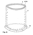
- the hollow body-shaped shuttering element 3 is preferably a hollow body with two openings, in particular a cylindrical hollow body, in particular preferably a substantially circular-cylindrical hollow body, most preferably a circular-cylindrical hollow body.
- the hollow body-shaped shuttering element 3 is a hollow body produced by deep-drawing or extrusion, as shown in FIG. 2 is shown, or a curved planar body which overlaps in its longitudinal direction.
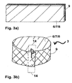
- FIG. 3a shows a possible flat body, or FIG. 3b after molding to a hollow body-shaped shuttering element lateral overlap with itself.
- the flat body can be connected to itself in various ways in the overlapping region 14 to form a hollow body, for example by gluing or mechanical connection means.
- the overlapping area is secured with at least one clip-shaped holding element, as shown in FIG FIG. 3b is shown.
- the overlapping area 14 is 2 - 30 cm, measured from the axial longitudinal edges in the longitudinal direction along the flat body.
Description
- Die vorliegende Erfindung bezieht sich auf ein Verfahren zum Abdichten eines einem Pfahl zugeordneten Durchbruchs in einer Dichtungsbahn im Baubereich.
- Obwohl auf beliebige Baubereiche anwendbar, werden die vorliegende Erfindung sowie die ihr zugrunde liegende Problematik nachfolgend mit Bezug auf einen Bohrpfahl näher erläutert.
- Bohrpfähle werden beispielsweise für Fundamentgründungen eingesetzt, insbesondere in weichen Untergründen. Zu ihrer Herstellung wird ein Bohrloch mit der gewünschten Tiefe hergestellt und ein Bohrpfahl in das Bohrloch eingebracht oder der Bohrpfahl gleich direkt in den Untergrund getrieben.
- Beim Bau eines Betonbauwerks wird der Untergrund typischerweise mit einer Dichtungsbahn abgedeckt, um ein Eindringen von Wasser aus dem Untergrund in das Bauwerk zu verhindern.
- Typischerweise werden die Bohrpfähle direkt oder indirekt mit dem Bauwerk verbunden, wofür die Dichtungsbahn durchstossen werden muss. Dabei entsteht im Bereich des Durchstosses zwischen Dichtungsbahn und Bohrpfahl ein Bereich, durch welchen Feuchtigkeit aus dem Untergrund in das Bauwerk gelangen kann, so wie das aus
WO 2010/028766 A1 hervor geht. - Aufgabe der vorliegenden Erfindung ist es daher, ein Verfahren der eingangs genannten Art dahingehend zu verbessern, dass Feuchtigkeit aus dem Untergrund nicht im Bereich des Durchstosses zwischen Dichtungsbahn und Bohrpfahl einzudringen vermag.
- Erfindungsgemäss wird dies durch die Merkmale des ersten Anspruches erreicht.
- Kern der Erfindung ist also ein Verfahren zur Abdichtung von Pfählen in Untergründen im Baubereich unter Verwendung eines hohlkörperförmigen Schalungselements. Das Verfahren umfasst die Schritte:
- 1) Anbringen einer Schottschicht am Untergrund;
- 2) Einbringen eines Pfahls in den Untergrund, wobei der Pfahl die Schottschicht durchdringend angeordnet ist;
- 3) Anbringen eines hohlkörperförmigen Schalungselements entlang der Längsmittelachse des Pfahls, wobei das hohlkörperförmige Schalungselement den Pfahl umgibt;
- 4) Einbringen von mineralischem Bindemittel in den Zwischenbereich zwischen Pfahl und hohlkörperförmigem Schalungselement;
- 5) Verbinden von Schottschicht und hohlkörperförmigem Schalungselement.
- Das hohlkörperförmige Schalungselement weist auf der dem Pfahl zugewandten Seite eine Kontaktschicht auf, welche eine Verbundschicht aus einem porösen Material und/oder ein Dichtmittel aufweist.
- Dies ist dahingehend von Vorteil, dass das eingebrachte mineralische Bindemittel sich im Wesentlichen fest mit der Kontaktschicht verbindet und dadurch ein Hinterlaufen des hohlkörperförmigem Schalungselements mit Feuchtigkeit aus dem Untergrund verhindert wird.
- Weiter kann mit diesem Verfahren auf das Entfernen der Schalung und dadurch auf einen zusätzlichen Arbeitschritt verzichtet werden, da das hohlkörperförmige Schalungselement als Bestandteil im Bauwerk verbleibt und dabei eine Abdichtfunktion übernimmt.
- Weitere vorteilhafte Ausgestaltungen der Erfindung ergeben sich aus den Unteransprüchen.
- Weitere Aspekte der Erfindung sind Gegenstand weiterer unabhängiger Ansprüche.
- Im Folgenden werden anhand der Zeichnungen Ausführungsbeispiele der Erfindung näher erläutert.
- Es zeigen
Fig. 1a, 1b und1c einen seitlichen Querschnitt durch einen abgedichteten Pfahl. - Es zeigt
Fig. 2 eine seitliche Ansicht eines hohlkörperförmigen Schalungselements. - Es zeigen
Fig. 3a und 3b seitliche Ansichten eines flächiger Körpers vor (3a), bzw. nach (3b) dem Formen zu einem hohlkörperförmigen Schalungselement durch seitliches Überlappen mit sich selbst. - Es sind nur die für das unmittelbare Verständnis der Erfindung wesentlichen Elemente gezeigt.
- In den
Figuren 1a, 1b und1c sind ein seitlicher Querschnitt durch einen abgedichteten Pfahl nach dem erfindungsgemässen Verfahren gezeigt. - Typischerweise handelt es sich bei dem Pfahl 1 um einen Pfahl im Baubereich, welcher in einen Untergrund 2 eingelassen wird. Entsprechend dem Nutzungszweck können Länge, Durchmesser, Material, Ausbildung der Pfähle variieren. Typischerweise besteht der Pfahl aus Materialien ausgewählt aus der Gruppe bestehend aus Holz, Metall und erhärteten mineralischen Bindemitteln, vorzugsweise aus erhärteten mineralischen Bindemitteln, insbesondere bevorzugt aus Beton. Ein solcher Pfahl hat vorzugsweise eine Länge von 5-25 Metern und vorzugsweise einen Durchmesser von 0.3-2 Metern, insbesondere 0.6-1.2 Metern.
- Vorzugsweise handelt es sich um einen Bohrpfahl. Der Pfahl 1 kann weiter auf seinem der Schottschicht 4 zugewandten Ende Trägerelemente 11 aufweisen, welche beispielsweise zu einer breiten Verteilung der Traglast, respektive Verankerungsbelastung, benötigt werden.
- Das erfindungsgemässe Verfahren umfassend den Schritt 1) des Anbringens einer Schottschicht 4 am Untergrund 2. Bei dem Untergrund 2 handelt es sich typischerweise um das Erdreich, der Untergrund kann waagrecht sein oder auch nicht, vorzugsweise ist der Untergrund im Wesentlichen waagrecht.
- Bei der Schottschicht 4 handelt es sich typischerweise um eine Abdichtungsbahn, welche geeignet ist, ein Bauwerk gegen Feuchtigkeit aus dem Untergrund abzudichten. Die Schottschicht kann aus allen Materialien bestehen, welche auch bei hohen Flüssigkeitsdrücken eine ausreichende Dichtheit gewährleisten. Typischerweise weist die Schottschicht eine hohe Beständigkeit gegen Wasserdruck auf, sowie gute Werte in Weiterreissversuchen und Perforationsversuchen.
- Typischerweise ist die Schottschicht eine Thermoplastschicht, vorzugsweise ist die Schottschicht ausgewählt aus Materialien aus der Gruppe bestehend aus Polyethylen mit hoher Dichte (HDPE), Polyethylen mit mittlerer Dichte (MDPE), Polyethylen mit tiefer Dichte (LDPE), Polyethylen (PE), Polyethylenterephthalat (PET), Polystyrol (PS), Polyvinylchlorid (PVC), Polyamide (PA), Ethylen-Vinylacetat (EVA), chlorsulfoniertes Polyethylen, Thermoplastische Polyolefine (TPO), Ethylen-Propylen-Dien-Kautschuk (EPDM) und Mischungen davon.
- Die Schottschicht kann eine Dicke von 0.1 - 5 mm, insbesondere 0.5-3.5 mm, bevorzugt 1.5 - 2.5 mm, aufweisen.
- Das erfindungsgemässe Verfahren umfasst weiter den Schritt 2) des Einbringens des Pfahls 1 in den Untergrund 2. Dies kann vor oder nach dem Schritt 1) geschehen. Das Einbringen erfolgt typischerweise durch Bohr- oder Rammverfahren in den Untergrund eingebracht. Solche Verfahren sind dem Fachmann bekannt.
- Der Pfahl 1 wird derart angeordnet, dass er die Schottschicht 4 durchdringt. Dies kann dadurch erreicht werden, dass beim Einbringen des Pfahls 1 in den Untergrund 2 die Schottschicht 4 vom Pfahl durchstossen wird. Es kann jedoch auch dadurch erreicht werden, dass nach dem Einbringen des Pfahls in den Untergrund die Schottschicht an den Untergrund angebracht wird und der Bereich des Untergrunds, in dem der Pfahl eingelassen ist, frei von Schottschicht gelassen wird. Dies kann beispielsweise dadurch erreicht werden, dass in diesen Bereichen Aussparungen aus der Schottschicht geschnitten werden und die Schottschicht entsprechend auf dem Untergrund platziert wird, dass erwähnte Aussparungen über den Pfahlenden zu liegen kommen.
- Weiter umfasst das erfindungsgemässe Verfahren den Schritt 3) des Anbringens eines hohlkörperförmigen Schalungselements 3 entlang der Längsmittelachse des Pfahls 1, wobei das hohlkörperförmige Schalungselement den Pfahl umgibt.
- Der Teil des Pfahls, welcher sich ausserhalb des Untergrunds befindet wird typischerweise entlang der im Wesentlichen gesamten Länge, wie in
Figur 1 a oder 1 c gezeigt, oder nur einem Teil seiner Länge, wie inFigur 1b gezeigt, vom hohlkörperförmigen Schalungselement umgeben, vorzugsweise entlang der im Wesentlichen gesamten Länge. Unter "im Wesentlichen gesamten Länge" wird im vorliegenden Fall verstanden, dass nahe des Untergrunds ein Bereich von wenigen Zentimetern oder Millimetern entlang der Längsachse des Pfahls nicht vom hohlkörperförmigen Schalungselement umgeben sein kann, beispielsweise wenn das hohlkörperförmige Schalungselement auf der Schottschicht angeordnet wird, wie inFigur 1 a gezeigt, wobei inFigur 1a der Pfahl im Bereich, welcher der Dicke der Schottschicht entspricht, nicht vom hohlkörperförmigen Schalungselement umgeben ist. - Im Fall, wo der ausserhalb des Untergrunds befindliche Teil der Pfahls entlang der im Wesentlichen gesamten Länge vom hohlkörperförmigen Schalungselement umgeben ist, kann durch das Einbringen von mineralischem Bindemittel 5 in den Zwischenbereich 12 zwischen Pfahl und hohlkörperförmigem Schalungselement der Pfahl vollständig mit mineralischem Bindemittel bedeckt werden. Dies ist dem Verhindern des Hinterlaufens zuträglich.
- Es ist daher von Vorteil, dass in Schritt 4) das der Schottschicht 4 zugewandte Ende des Pfahls 1 im Wesentlichen vollständig, insbesondere vollständig, mit mineralischem Bindemittel 5 bedeckt wird. Weiter kann es vorteilhaft sein, das erhärtete mineralische Bindemittel nachträglich noch mit einer Schicht aus Epoxidharz zu überschichten und somit zu versiegeln, typischerweise mit einer Schichtdicke von 0.5 - 5cm, vorzugsweise von 1 - 2 cm. Dieses Versiegeln eignet sich sowohl für den Fall, in dem der Teil des Pfahls, welcher sich ausserhalb des Untergrunds befindet, im Wesentlichen entlang der gesamten Länge vom hohlkörperförmigen Schalungselement umgeben ist, als auch für Ausführungsformen, wo dies nur auf einem Teil seiner Länge der Fall ist.
- Das erfindungsgemässe Verfahren umfasst weiter den Schritt 4) des Einbringens von mineralischem Bindemittel 5 in den Zwischenbereich 12 zwischen Pfahl 1 und hohlkörperförmigem Schalungselement 3.
- Bei den mineralischen Bindemitteln handelt es sich um hydraulische Bindemittel und/oder latent hydraulische Bindemittel und/oder puzzolanische Bindemittel. Unter dem Begriff hydraulische Bindemittel werden im vorliegenden Dokument Bindemittel verstanden, die auch unter Wasser abbinden, respektive erhärten, wie beispielsweise hydraulischer Kalk oder Zement. Unter dem Begriff latent hydraulische Bindemittel werden im vorliegenden Dokument Bindemittel verstanden, die erst durch Einwirkung von Zusätzen (Anregern) abbinden, respektive erhärten, wie beispielsweise Hüttensand. Unter dem Begriff puzzolanische Bindemittel werden im vorliegenden Dokument Bindemittel verstanden, die nicht selbstständig abbinden sondern nach Feuchtlagerung durch Bindung von Calciumhydroxid festigkeitsbildende Reaktionsprodukte liefern, wie beispielsweise Flugasche, Silica fume, sowie natürliche Puzzolane, wie z. B. Trass.
- Bei den mineralischen Bindemitteln handelt es sich typischerweise um auf Zement basierenden Bindemitteln, vorzugsweise um hochfesten Vergussmörtel. Das Einbringen erfolgt typischerweise durch Vergiessen. Solche Verfahren sind dem Fachmann bekannt.
- Weiter ist es vorteilhaft, wenn das in Schritt 4) in den Zwischenbereich 12 eingebrachte mineralische Bindemittel darin verbleibt und darin erhärtet.
- Weiter ist es von Vorteil, dass sich das in Schritt 4) eingebrachte mineralische Bindemittel 5 im Wesentlichen fest mit der Kontaktschicht 6 verbindet und insbesondere ein Hinterlaufen des hohlkörperförmigen Schalungselements 3 durch drückendes Wasser 10 des Untergrunds verhindert.
- Wie beispielsweise in
Figur 1a, 1b und1c ersichtlich, weist das hohlkörperförmige Schalungselement auf der dem Pfahl zugewandten Seite eine Kontaktschicht 6 auf. Die Kontaktschicht 6 weist eine Verbundschicht 7 aus einem porösen Material und/oder ein Dichtmittel 8 auf. - Die Verbundschicht kann aus allen Materialien bestehen, insbesondere aus solchen, welche von flüssigen mineralischen Bindemitteln, insbesondere Beton, gut durchdrungen werden und mit dem erhärteten mineralischen Bindemittel einen guten Verbund ausbilden.
- Unter dem Begriff "Verbundschicht" wird in diesem Dokument eine Schicht verstanden, die den Verbund zu dem aufgetragenen mineralischen Bindemittel gewährleisten kann.
- Die Verbundschicht kann also eine im Wesentlichen feste Verbindung mit mineralischen Bindemitteln eingehen, wenn besagte mineralischen Bindemittel vor ihrer Aushärtung mit der Verbundschicht in Kontakt gebracht werden.
- Die Verbundschicht besteht aus einem porösen Material. Eine poröse Struktur ist der Elastizität der Verbundschicht zuträglich, sie kann dadurch besser Zug- und Scherkräfte aushalten. Andererseits führt sie zu einer guten Aufnahme von flüssigen mineralischen Bindemitteln und somit zu einem guten Verbund mit dem flüssigen sowie dem ausgehärteten mineralischen Bindemittel.
- Vorzugsweise ist die Verbundschicht ein Faserwerkstoff. Unter Faserwerkstoff ist im ganzen vorliegenden Dokument ein Werkstoff zu verstehen, welcher aus Fasern aufgebaut ist. Die Fasern umfassen oder bestehen aus organischem oder synthetischem Material. Insbesondere handelt es sich um Zellulose-, Baumwollfasern, Proteinfasern oder um synthetische Fasern. Als synthetische Fasern sind vor allem bevorzugt Fasern aus Polyester oder aus einem Homo- oder Copolymeren von Ethylen und/oder Propylen oder aus Viskose zu nennen. Die Fasern können hierbei Kurzfasern oder Langfasern, gesponnene, gewebte oder ungewebte Fasern oder Filamente sein. Weiterhin können die Fasern gerichtete oder gestreckte Fasern sein. Weiterhin kann es vorteilhaft sein, unterschiedliche Fasern, sowohl in Geometrie als auch Zusammensetzung, miteinander zu verwenden.
- Weiterhin umfasst der Faserwerkstoff Hohlräume. Diese Hohlräume werden durch geeignete Herstellverfahren aufgebaut. Vorzugsweise sind die Hohlräume zumindest teilweise offen und erlauben das Eindringen von flüssigen mineralischen Bindemitteln.
- Der aus Fasern aufgebaute Körper kann auf die verschiedensten dem Fachmann bekannten Verfahren hergestellt werden. Insbesondere kommen Körper zum Einsatz, die ein Gewebe, Gelege oder Gewirke sind.
- Besonders bevorzugt als Faserwerkstoff ist ein Filz oder Vlies.
- Vorteilhafterweise ist die Verbundschicht ein thermoplastisches Material und das Material ist ausgewählt aus der Gruppe umfassend Polyethylen mit hoher Dichte (HDPE), Polyethylenterephthalat (PET), Polystyrol (PS), Polypropylen (PP), Polyvinylchlorid (PVC), Polyamid (PA) und Kombinationen davon.
- Weiterhin kann die Verbundschicht 7 eine Dicke von 0.5 - 30 mm, bevorzugt 2 - 10 mm, aufweisen.
- Als Dichtmittel 8 kommen alle Materialien in Frage, welche geeignet sind, den Durchgang von Flüssigkeiten, insbesondere von Wasser, zwischen dem erhärteten mineralischen Bindemittel und dem hohlkörperförmigen Schalungselement zu reduzieren, respektive zu verhindern.
- Vorzugsweise ist das Dichtmittel ein Thermoplast oder ein thermoplastisches Elastomer. Thermoplastische Elastomere haben den Vorteil, dass das Dichtmittel dadurch über eine gute Elastizität gegenüber Horizontalund Vertikalverschiebungen, insbesondere Verschiebungen aufgrund von mechanischen Spannungen im Bauwerk, verfügt. Eine gute Elastizität des Dichtmittels verhindert ein Reissen oder Ablösen des Dichtmittels und somit ein Versagen der Dichtung.
- Als thermoplastische Elastomere werden in diesem Dokument Kunststoffe verstanden, welche die mechanischen Eigenschaften von vulkanisierten Elastomeren mit der Verarbeitbarkeit von Thermoplasten vereinen. Typischerweise sind derartige thermoplastische Elastomere BlockCopolymere mit Hart- und Weichsegmenten oder so genannte Polymerlegierungen mit entsprechend thermoplastischen und elastomeren Bestandteilen.
- Weitere vorteilhafte Dichtmittel sind Dichtmittel, welche ausgewählt sind aus der Gruppe bestehend aus Acrylatverbindungen, Polyurethanpolymeren, Silan-terminierten Polymeren und Polyolefinen.
- Es ist weiter von Vorteil, wenn das Dichtmittel 8 ein Haftklebstoff und/oder ein Schmelzklebstoff ist. Dies gewährleistet einen guten Verbund und eine gute Haftung zwischen mineralischem Bindemittel und dem hohlkörperförmigen Schalungselement und vermindert somit das Ablösen des Dichtmittels und somit ein Versagen der Dichtung.
- Haftklebstoffe und Schmelzklebstoff sind dem Fachmann allgemein bekannt und sind beschrieben in CD Römpp Chemie Lexikon, Version 1.0, Georg Thieme Verlag, Stuttgart.
- Es ist weiter vorteilhaft, wenn das Dichtmittel Quellstoffe enthält, welche bei Kontakt mit Wasser ihr Volumen auf ein mehrfaches vergrössern, typischerweise zwischen 200 - 1000% des ursprünglichen Volumens. Zusätzlich zur Volumenvergrösserung können gewisse Quellstoffe auch mit Wasser chemisch reagieren. Beispiele von solchen Quellstoffen sind Quellstoffe auf Polyurethanbasis, insbesondere silanmodifizierte Polymere, die durch Feuchtigkeit zu einem elastischen Produkt aushärten. Ein weiteres Beispiel für Quellstoffe sind Bentonit-Butyl-Kautschuke.
- Vorteilhafterweise handelt es sich bei den Quellstoffen um Quellstoffe, die durch eine Beschichtung zeitlich verzögert mit Wasser reagieren, damit insbesondere während dem Kontakt mit feuchtem mineralischen Bindemittel die Quellstoffe nicht oder nur wenig quellen und für den Fall des Hinterlaufens des hohlkörperförmigen Dichtungselements mit drückendem Wasser 10 quellfähig bleiben.
- Weiterhin kann das Dichtmittel eine Dicke von 0.5 - 30 mm, bevorzugt 2 - 10 mm aufweisen.
- Es kann weiter vorteilhaft sein, wenn das hohlkörperförmige Schalungselement 3 mindestens einen Injektionsschlauch aufweist, welcher auf der dem Pfahl 1 zugewandten Seite des hohlkörperförmigen Schalungselements 3 angeordnet ist. Durch den Injektionsschlauch lassen sich im Falle eines Hinterlaufens des hohlkörperförmigen Schalungselements 3 durch drückendes Wasser 10 des Untergrunds geeignete Injektionsmaterialien wie Acrylatverbindungen, Polyurethanpolymere oder Zement nach dem Erhärten des mineralischen Bindemittels nachträglich noch einbringen und somit ein Hinterlaufen einschränken, insbesondere verhindern.
- Das hohlkörperförmige Schalungselement 3 kann weiter eine Stützschicht 9 aus Metall, insbesondere aus Stahl, oder einem Kunststoff, insbesondere einem thermoplastischen Kunststoff, welcher ausgewählt ist aus der Gruppe bestehend aus Polyethylen mit hoher Dichte (HDPE), Polyethylen mit mittlerer Dichte (MDPE), Polyethylen mit tiefer Dichte (LDPE), Polyethylen (PE), Polyethylenterephthalat (PET), Polystyrol (PS), Polyvinylchlorid (PVC), Polyamide (PA), Ethylen-Vinylacetat (EVA), chlorsulfoniertes Polyethylen, Thermoplastische Polyolefine (TPO) und Ethylen-Propylen-Dien-Kautschuk (EPDM), aufweisen.
- Typischerweise hat die Stützschicht 9 eine Stärke von 0.2 - 5 mm, im Fall, dass es sich um eine Stützschicht aus Metall handelt insbesondere von 0.6 - 2 mm, im Fall, dass es sich um eine Stützschicht aus Kunststoff handelt insbesondere von 0.5 - 5 mm.
- Es ist insbesondere von Vorteil, wenn während oder nach Schritt 4) das hohlkörperförmige Schalungselement 3 im Wesentlichen nicht ausgewölbt oder verbogen, insbesondere nicht ausgewölbt oder verbogen, wird. Dies ist dahingehend von Vorteil, weil dadurch eine kontrollierte Auffüllhöhe und Abmessung des mit mineralischem Bindemittel gefüllten Schalungselement gewährleistet werden kann. Weiter wird dadurch eine Beschädigung des Schalungselements durch die durch das Gewicht des Bindemittels entstehenden Kräfte verhindert.
- Weiter ist es von Vorteil wenn das hohlkörperförmige Schalungselement 3 eine Höhe von 2 - 50 cm, insbesondere 5 - 30 cm, aufweist.
- Das hohlkörperförmige Schalungselement 3 kann im Wesentlichen auf der dem Untergrund 2 abgewandten Seite der Schottschicht 4 angeordnet sein, wie dies in den
Figuren 1a und 1b ersichtlich ist, oder auch nicht. Das hohlkörperförmige Schalungselement kann auch auf der dem Untergrund 2 abgewandten sowie zugewandten Seite der Schottschicht 4 angeordnet sein, wie dies in derFigur 1c gezeigt wird. - Weiter ist es von Vorteil wenn das hohlkörperförmige Schalungselement 3 im Wesentlichen auf der dem Untergrund 2 abgewandten Seite der Schottschicht 4 angeordnet ist. Unter "im Wesentlichen auf der dem Untergrund abgewandten Seite der Schottschicht" wird im vorliegenden Fall verstanden, dass mehr als 80%, vorzugsweise mehr als 90%, insbesondere bevorzugt mehr als 95%, der Höhe des hohlkörperförmigen Schalungselements auf der dem Untergrund 2 abgewandten Seite der Schottschicht 4 angeordnet ist. Es ist weiter bevorzugt, wenn das hohlkörperförmige Schalungselement 3 vollständig auf der dem Untergrund 2 abgewandten Seite der Schottschicht 4 angeordnet ist.
- Weiter umfasst das erfindungsgemässe Verfahren den Schritt 5) des Verbindens von Schottschicht 4 und hohlkörperförmigem Schalungselement 3. Das Verbinden kann auf jede Art und Weise geschehen, welche eine im Wesentlichen wasserdichte Verbindung zwischen Schottschicht 4 und hohlkörperförmigem Schalungselement 3 gewährleistet. Vorzugsweise erfolgt das Verbinden durch Verschweissen und/oder Verkleben und/oder mechanischem Verbinden. Schritt 5) kann vor oder nach Schritt 4) ausgeführt werden. Vorzugsweise wird Schritt 5) nach Schritt 4) ausgeführt.
- Vorzugsweise weist das hohlkörperförmige Schalungselement mindestens ein Verbindungselement 13 auf, welches das hohlkörperförmige Schalungselement 3 mit der Schottschicht 4 verbindet, wie dies in den
Figuren 1 a und 1 b gezeigt ist. Bei dem Verbindungselement handelt es sich vorzugsweise um ein das hohlkörperförmige Schalungselement umgebendes Band, welches radial nach aussen gerichtet angebracht ist. Das Band hat typischerweise eine Breite von 2 - 50 cm, insbesondere 5 - 30 cm, und eine Dicke von 0.2 - 5 mm. - Vorzugsweise wird in Schritt 5) das Verbinden von Schottschicht 4 und hohlkörperförmigem Schalungselement 3 durch Verschweissen und/oder Verkleben und/oder mechanischem Verbinden von Verbindungselement 13 und Schottschicht 4 ausgeführt. Typischerweise führt das Verbinden zu einem Überlappungsbereich von Verbindungselement und Schottschicht von 2 - 15 cm. Es ist weiter vorteilhaft, wenn das Verbindungselement an der der Schottschicht zugewandten Randkante des hohlkörperförmigen Schalungselements angeordnet ist, wie dies beispielsweise in den
Figuren 1 a und 1 b ersichtlich ist. - Bei dem hohlkörperförmigen Schalungselement 3 handelt es sich vorzugsweise um einen Hohlkörper mit zwei Öffnungen, insbesondere einen zylindrischen Hohlkörper, insbesondere bevorzugt um einen im Wesentlichen kreiszylindrischen Hohlkörper, am meisten bevorzugt um einen kreiszylindrischen Hohlkörper.
- Vorzugsweise ist das hohlkörperförmige Schalungselement 3 ein durch Tiefziehen oder Extrusion hergestellter Hohlkörper, wie dies in
Figur 2 gezeigt ist, oder ein gebogener flächiger Körper, der sich in seiner Längsrichtung überlappt.Figur 3a zeigt einen möglichen flächigen Körper vor, bzw.Figur 3b nach dem Formen zu einem hohlkörperförmigen Schalungselement durch seitliches Überlappen mit sich selbst. Der flächige Körper kann auf verschiedene Arten im Überlappungsbereich 14 mit sich selber verbunden werden, um einen Hohlkörper zu bilden, beispielsweise durch Kleben oder mechanische Verbindungsmittel. Vorzugsweise wird der Überlappungsbereich mit mindestens einem klammerförmigen Halteelement gesichert, wie dies inFigur 3b gezeigt ist. - Vorzugsweise beträgt der Überlappungsbereich 14 2 - 30 cm, gemessen von den axialen Längskanten in die Längsrichtung entlang dem flächigen Körper.
- Wird das hohlkörperförmige Schalungselement 3 nach dem Erstarren des in Schritt 4) eingebrachten mineralischen Bindemittel nicht entfernt, hat dies den grossen Vorteil, dass mit diesem Verfahren auf das Entfernen der Schalung und dadurch auf einen zusätzlichen Arbeitschritt verzichtet werden kann, da das hohlkörperförmige Schalungselement als Bestandteil im Bauwerk verbleibt und dabei eine Abdichtfunktion übernimmt.
-
- 1
- Pfahl
- 2
- Untergrund
- 3
- Hohlkörperförmiges Schalungselement
- 4
- Schottschicht
- 5
- Mineralisches Bindemittel
- 6
- Kontaktschicht
- 7
- Verbundschicht
- 8
- Dichtmittel
- 9
- Stützschicht
- 10
- Drückendes Wasser
- 11
- Trägerelement
- 12
- Zwischenbereich zwischen Pfahl und hohlkörperförmigem Schalungselement
- 13
- Verbindungselement
- 14
- Überlappungsbereich
Claims (12)
- Verfahren zur Abdichtung von Pfählen (1) in Untergründen (2) im Baubereich unter Verwendung eines hohlkörperförmigen Schalungselements (3) umfassend die Schritte:1) Anbringen einer Schottschicht (4) am Untergrund (2);2) Einbringen eines Pfahls (1) in den Untergrund (2), wobei der Pfahl (1) die Schottschicht (2) durchdringend angeordnet ist;3) Anbringen eines hohlkörperförmigen Schalungselements (3) entlang der Längsmittelachse des Pfahls (1), wobei das hohlkörperförmige Schalungselement (3) den Pfahl (1) umgibt;4) Einbringen von mineralischem Bindemittel (5) in den Zwischenbereich (12) zwischen Pfahl (1) und hohlkörperförmigem Schalungselement (3),5) Verbinden von Schottschicht (4) und hohlkörperförmigem Schalungselement (3);wobei das hohlkörperförmige Schalungselement (3) auf der dem Pfahl (1) zugewandten Seite eine Kontaktschicht (6) aufweist, welche eine Verbundschicht (7) aus einem porösen Material und/oder ein Dichtmittel (8) aufweist.
- Verfahren gemäss Anspruch 1, dadurch gekennzeichnet, dass das hohlkörperförmige Schalungselement (3) im Wesentlichen auf der dem Untergrund (2) abgewandten Seite der Schottschicht (4) angeordnet ist.
- Verfahren gemäss Anspruch 1 oder 2, dadurch gekennzeichnet, dass in Schritt 4) das der Schottschicht (4) zugewandte Ende des Pfahls (1) im Wesentlichen vollständig mit mineralischem Bindemittel (5) bedeckt wird.
- Verfahren gemäss einem der vorgehenden Ansprüche, dadurch gekennzeichnet, dass während oder nach Schritt 4) das hohlkörperförmige Schalungselement (3) im Wesentlichen nicht ausgewölbt oder verbogen wird.
- Verfahren gemäss einem der vorgehenden Ansprüche, dadurch gekennzeichnet, dass das hohlkörperförmige Schalungselement (3) eine Stützschicht (9) aus Metall oder einem Kunststoff aufweist, vorzugsweise hat die Stützschicht (9) eine Stärke von 0.2 - 5 mm.
- Verfahren gemäss einem der vorgehenden Ansprüche, dadurch gekennzeichnet, dass das hohlkörperförmige Schalungselement (3) eine Höhe von 2 - 50 cm aufweist.
- Verfahren gemäss einem der vorgehenden Ansprüche, dadurch gekennzeichnet, dass das hohlkörperförmige Schalungselement (3) nach dem Erstarren des in Schritt 4) eingebrachten mineralischen Bindemittel nicht entfernt wird.
- Verfahren gemäss einem der vorgehenden Ansprüche, dadurch gekennzeichnet, dass sich das in Schritt 4) eingebrachte mineralische Bindemittel (5) im Wesentlichen fest mit der Kontaktschicht (6) verbindet und insbesondere ein Hinterlaufen des hohlkörperförmigen Schalungselements (3) durch drückendes Wasser (10) des Untergrunds verhindert.
- Verfahren gemäss einem der vorgehenden Ansprüche, dadurch gekennzeichnet, dass das hohlkörperförmige Schalungselement (3) ein zylindrischer Hohlkörper ist.
- Verfahren gemäss einem der vorgehenden Ansprüche, dadurch gekennzeichnet, dass das hohlkörperförmige Schalungselement (3);
ein durch Tiefziehen oder Extrusion hergestellter Hohlkörper ist, oder
ein gebogener flächiger Körper, der sich in seiner Längsrichtung überlappt, wobei der Überlappungsbereich vorzugsweise mit mindestens einem klammerförmigen Halteelement gesichert ist, weiter bevorzugt beträgt der Überlappungsbereich (14) 2 - 30 cm, gemessen von den axialen Längskanten in die Längsrichtung entlang dem flächigen Körper. - Verfahren gemäss einem der vorgehenden Ansprüche, dadurch gekennzeichnet, dass das hohlkörperförmige Schalungselement (3) mindestens ein Verbindungselement (13) aufweist, welches vorzugsweise an der der Schottschicht (4) zugewandten Randkante des hohlkörperförmigen Schalungselements (3) angeordnet ist und welches das hohlkörperförmige Schalungselement (3) mit der Schottschicht (4) verbindet, vorzugsweise wird in Schritt 5) das Verbinden von Schottschicht (4) und hohlkörperförmigem Schalungselement (3) durch Verschweissen und/oder Verkleben und/oder mechanischem Verbinden von Verbindungselement (13) und Schottschicht (4) ausgeführt.
- Verfahren gemäss einem der vorgehenden Ansprüche, dadurch gekennzeichnet, dass das hohlkörperförmige Schalungselement (3) mindestens einen Injektionsschlauch aufweist, welcher auf der dem Pfahl (1) zugewandten Seite des hohlkörperförmigen Schalungselements (3) angeordnet ist.
Priority Applications (1)
| Application Number | Priority Date | Filing Date | Title |
|---|---|---|---|
| EP20110797008 EP2652207B1 (de) | 2010-12-17 | 2011-12-14 | Schalungselement |
Applications Claiming Priority (3)
| Application Number | Priority Date | Filing Date | Title |
|---|---|---|---|
| EP20100195626 EP2466013A1 (de) | 2010-12-17 | 2010-12-17 | Schalungselement |
| PCT/EP2011/072766 WO2012080341A1 (de) | 2010-12-17 | 2011-12-14 | Schalungselement |
| EP20110797008 EP2652207B1 (de) | 2010-12-17 | 2011-12-14 | Schalungselement |
Publications (2)
| Publication Number | Publication Date |
|---|---|
| EP2652207A1 EP2652207A1 (de) | 2013-10-23 |
| EP2652207B1 true EP2652207B1 (de) | 2015-04-08 |
Family
ID=43796150
Family Applications (2)
| Application Number | Title | Priority Date | Filing Date |
|---|---|---|---|
| EP20100195626 Withdrawn EP2466013A1 (de) | 2010-12-17 | 2010-12-17 | Schalungselement |
| EP20110797008 Not-in-force EP2652207B1 (de) | 2010-12-17 | 2011-12-14 | Schalungselement |
Family Applications Before (1)
| Application Number | Title | Priority Date | Filing Date |
|---|---|---|---|
| EP20100195626 Withdrawn EP2466013A1 (de) | 2010-12-17 | 2010-12-17 | Schalungselement |
Country Status (7)
| Country | Link |
|---|---|
| US (1) | US9127433B2 (de) |
| EP (2) | EP2466013A1 (de) |
| JP (1) | JP5960715B2 (de) |
| CN (1) | CN103228845B (de) |
| BR (1) | BR112013011368A2 (de) |
| RU (1) | RU2581066C2 (de) |
| WO (1) | WO2012080341A1 (de) |
Families Citing this family (6)
| Publication number | Priority date | Publication date | Assignee | Title |
|---|---|---|---|---|
| CN103821180B (zh) * | 2014-03-02 | 2015-07-29 | 山东交通学院 | 一种混凝土伸缩缝双止水结构 |
| CN104727349B (zh) * | 2014-03-02 | 2016-12-07 | 宁波市鄞州丰茂水利工程有限公司 | 一种混凝土伸缩缝双止水结构固定件 |
| AU2016376849B2 (en) * | 2015-12-23 | 2021-05-20 | Sika Technology Ag | Contact layer with a solid filler component |
| CN205742241U (zh) * | 2016-06-28 | 2016-11-30 | 广东中科华大工程技术检测有限公司 | 一种钢管灌注预应力稳压封桩装置 |
| CN108589797B (zh) * | 2018-06-06 | 2023-12-05 | 中铁第四勘察设计院集团有限公司 | 一种地下结构与墩柱分离式节点防水系统 |
| CN115369927A (zh) * | 2022-09-13 | 2022-11-22 | 中国三冶集团有限公司 | 一种垃圾坑底板桩头防渗结构施工方法 |
Family Cites Families (29)
| Publication number | Priority date | Publication date | Assignee | Title |
|---|---|---|---|---|
| US892592A (en) * | 1905-10-17 | 1908-07-07 | E G Siggers | Post and tile mold. |
| US1409422A (en) * | 1921-03-17 | 1922-03-14 | Harry E Squire | Process for producing composite piles |
| US2428070A (en) * | 1945-11-29 | 1947-09-30 | Frenkil Victor | Foundation pile |
| US3166871A (en) * | 1962-02-23 | 1965-01-26 | P L Montemurro | Apparatus for setting a fence post in concrete |
| DE2147051A1 (de) * | 1971-09-21 | 1973-04-05 | Dyckerhoff & Widmann Ag | Verfahren zum herstellen eines druckpfahles im boden |
| US4019301A (en) * | 1974-07-15 | 1977-04-26 | Fox Douglas L | Corrosion-resistant encasement for structural members |
| DE2734525A1 (de) * | 1977-07-30 | 1979-02-08 | Dynamit Nobel Ag | Randbefestigung von kunststoffdichtungsbahnen an einem bauwerk |
| JPS6030485Y2 (ja) * | 1982-08-14 | 1985-09-12 | 藤森工業株式会社 | 固定部材打込用部材 |
| JPH0126891Y2 (de) * | 1985-05-31 | 1989-08-11 | ||
| US4767095A (en) * | 1986-12-23 | 1988-08-30 | Fitzgerald John M | Concrete column form |
| US5175973A (en) * | 1988-06-14 | 1993-01-05 | Team, Inc. | Compression repair method and apparatus |
| RU2057847C1 (ru) * | 1992-09-15 | 1996-04-10 | Александр Сергеевич Петрашень | Способ усиления фундаментов |
| JP3192277B2 (ja) * | 1993-05-14 | 2001-07-23 | 新日本製鐵株式会社 | コンクリート柱 |
| US6471446B2 (en) * | 1996-12-02 | 2002-10-29 | Foundation Technologies, Inc. | Reduced skin friction bore casing |
| US5915884A (en) * | 1996-12-11 | 1999-06-29 | Surevoid Products, Inc. | Arcuate end corrugated paper form void |
| US5890844A (en) * | 1997-10-08 | 1999-04-06 | Schellhorn; Verne L. | Single engine soil processing system |
| JPH11315587A (ja) * | 1998-05-01 | 1999-11-16 | Taiheiyo Cement Corp | 構造物の防食被覆構造、防食工法および防食パネル |
| JP4063690B2 (ja) * | 2003-03-03 | 2008-03-19 | 鹿島建設株式会社 | 被覆型廃棄物最終処分場の構造物の遮水工法及びその構造 |
| JP2005194768A (ja) * | 2004-01-07 | 2005-07-21 | Murata Mach Ltd | コンクリート柱補修および/又は補強工法及び補修および/又は補強部材 |
| US7192219B2 (en) * | 2005-03-22 | 2007-03-20 | Dominick Graziosi | Pier boot and method for sealing a crawlspace |
| RU2305154C1 (ru) * | 2006-01-30 | 2007-08-27 | ГОУ ВПО "Санкт-Петербургский государственный архитектурно-строительный университет" | Способ возведения плитно-свайного фундамента |
| DE102006059044A1 (de) * | 2006-12-14 | 2008-06-19 | Fischerwerke Gmbh & Co. Kg | Verfahren und Anordnung zum Abdichten von Gebäuden |
| RU2385384C1 (ru) * | 2008-07-18 | 2010-03-27 | Общество с ограниченной ответственностью "МПО РИТА" | Способ изготовления узла сопряжения сваи с существующим фундаментом при его усилении (варианты) |
| RU2378454C1 (ru) * | 2008-08-14 | 2010-01-10 | Федеральное государственное образовательное учреждение высшего профессионального образования Кубанский государственный аграрный университет | Способ возведения свайно-плитного фундамента |
| IT1392652B1 (it) | 2008-09-11 | 2012-03-16 | Carpi Tech Bv Amsterdam Chiasso Branch | Metodo e sistema per il fissaggio di membrane impermeabili ad opere idrauliche |
| EP2177349A1 (de) | 2008-10-15 | 2010-04-21 | Sika Technology AG | Wasserdichte Membran |
| US8192111B2 (en) * | 2009-05-20 | 2012-06-05 | Gse Lining Technology, Inc. | Boot for geosynthetic layer |
| CN101691739B (zh) * | 2009-08-31 | 2011-04-20 | 天津市水利科学研究院 | 复合型自粘止水带及制作方法和施工方法 |
| CN101781885A (zh) * | 2010-03-12 | 2010-07-21 | 中国水电顾问集团中南勘测设计研究院 | 复合橡胶止水带以及贴坡式止水结构 |
-
2010
- 2010-12-17 EP EP20100195626 patent/EP2466013A1/de not_active Withdrawn
-
2011
- 2011-12-14 CN CN201180057481.4A patent/CN103228845B/zh not_active Expired - Fee Related
- 2011-12-14 RU RU2013117937/03A patent/RU2581066C2/ru not_active IP Right Cessation
- 2011-12-14 BR BR112013011368A patent/BR112013011368A2/pt not_active Application Discontinuation
- 2011-12-14 JP JP2013543760A patent/JP5960715B2/ja not_active Expired - Fee Related
- 2011-12-14 EP EP20110797008 patent/EP2652207B1/de not_active Not-in-force
- 2011-12-14 WO PCT/EP2011/072766 patent/WO2012080341A1/de active Application Filing
-
2013
- 2013-06-14 US US13/918,231 patent/US9127433B2/en not_active Expired - Fee Related
Also Published As
| Publication number | Publication date |
|---|---|
| JP2014501341A (ja) | 2014-01-20 |
| US9127433B2 (en) | 2015-09-08 |
| WO2012080341A1 (de) | 2012-06-21 |
| CN103228845A (zh) | 2013-07-31 |
| RU2581066C2 (ru) | 2016-04-10 |
| EP2466013A1 (de) | 2012-06-20 |
| RU2013117937A (ru) | 2015-01-27 |
| BR112013011368A2 (pt) | 2017-07-25 |
| CN103228845B (zh) | 2015-09-23 |
| EP2652207A1 (de) | 2013-10-23 |
| US20130279991A1 (en) | 2013-10-24 |
| JP5960715B2 (ja) | 2016-08-02 |
Similar Documents
| Publication | Publication Date | Title |
|---|---|---|
| EP2349707B1 (de) | Wasserdichte membran | |
| EP2652207B1 (de) | Schalungselement | |
| WO2011033122A1 (de) | Wasserdichte membran | |
| EP2756168A1 (de) | Tübbing mit thermoplastischer schottschicht | |
| DE102016107632A1 (de) | Platten- oder bahnförmige Dichtung für Bauwerke aus Beton sowie Verfahren zum Herstellen einer Verbundabdichtung im Wand-, Boden- und Deckenbereich von Bauwerken aus Materialien auf Zementbasis, insbesondere Beton | |
| DE4428591C2 (de) | Zwei- oder mehrlagige Kunststoffdichtungsbahn, Verfahren zum Abdichten von Bauten oder Bauwerksteilen mit einer Kunststoffdichtungsbahn sowie Verwendung derselben | |
| EP2093339B1 (de) | Vorrichtung zur halterung einer dichtung an einer abschalungsplatte | |
| DE202012102396U1 (de) | Fugenprofil und Anordnung aus mehreren Fugenprofilen für Fugen in einem Betonbelag | |
| DE2607317B2 (de) | Rohrformstück | |
| WO2006053737A1 (de) | Schichtaufbau | |
| EP2949462A1 (de) | Flächenabdichtelement für baukörper | |
| JP2015224470A (ja) | 盛土の安定化工法 | |
| EP1983157A1 (de) | Vorrichtung zum Abdichten eines einem Durchdringungselement zugeordneten Durchbruch in einer Dichtungsbahn | |
| EP3854952A1 (de) | Verfahren zum aufbau eines erdberührten bauwerks | |
| WO2011057996A1 (de) | Vorrichtung zum abdichten eines einem durchdringungselement zugeordneten durchbruchs in einer dichtungsbahn | |
| DE2233990C3 (de) | Vorrichtung zur Herstellung eines wenigstens gegen mechanische Kräfte gesicherten Anschlusses einer zur Abdichtung eines Bauwerkes verlegten Dichtungsbahn | |
| DE202021003197U1 (de) | Schwindrohrschuh zur zuverlässigen Stabilisierung und Verbindung der Ausrichtung eines Schwindrohres mit einem Fugenband | |
| DE202010006962U1 (de) | Entwässerungsrinne | |
| WO2017152890A1 (de) | Rückhaltewand | |
| DE202004020399U1 (de) | Schichtaufbau | |
| WO2014111583A1 (de) | Verfahren zur herstellung eines tübbing mit thermoplastischer schottschicht |
Legal Events
| Date | Code | Title | Description |
|---|---|---|---|
| PUAI | Public reference made under article 153(3) epc to a published international application that has entered the european phase |
Free format text: ORIGINAL CODE: 0009012 |
|
| 17P | Request for examination filed |
Effective date: 20130717 |
|
| AK | Designated contracting states |
Kind code of ref document: A1 Designated state(s): AL AT BE BG CH CY CZ DE DK EE ES FI FR GB GR HR HU IE IS IT LI LT LU LV MC MK MT NL NO PL PT RO RS SE SI SK SM TR |
|
| RIN1 | Information on inventor provided before grant (corrected) |
Inventor name: KLOSTER, MAGNUS Inventor name: MEYER, KLAUS Inventor name: WEBER, ULRICH K. |
|
| DAX | Request for extension of the european patent (deleted) | ||
| GRAP | Despatch of communication of intention to grant a patent |
Free format text: ORIGINAL CODE: EPIDOSNIGR1 |
|
| INTG | Intention to grant announced |
Effective date: 20141027 |
|
| GRAS | Grant fee paid |
Free format text: ORIGINAL CODE: EPIDOSNIGR3 |
|
| GRAA | (expected) grant |
Free format text: ORIGINAL CODE: 0009210 |
|
| AK | Designated contracting states |
Kind code of ref document: B1 Designated state(s): AL AT BE BG CH CY CZ DE DK EE ES FI FR GB GR HR HU IE IS IT LI LT LU LV MC MK MT NL NO PL PT RO RS SE SI SK SM TR |
|
| REG | Reference to a national code |
Ref country code: GB Ref legal event code: FG4D Free format text: NOT ENGLISH |
|
| REG | Reference to a national code |
Ref country code: CH Ref legal event code: EP |
|
| REG | Reference to a national code |
Ref country code: IE Ref legal event code: FG4D Free format text: LANGUAGE OF EP DOCUMENT: GERMAN |
|
| REG | Reference to a national code |
Ref country code: AT Ref legal event code: REF Ref document number: 720702 Country of ref document: AT Kind code of ref document: T Effective date: 20150515 |
|
| REG | Reference to a national code |
Ref country code: DE Ref legal event code: R096 Ref document number: 502011006555 Country of ref document: DE Effective date: 20150521 |
|
| REG | Reference to a national code |
Ref country code: NL Ref legal event code: VDEP Effective date: 20150408 |
|
| REG | Reference to a national code |
Ref country code: LT Ref legal event code: MG4D |
|
| PG25 | Lapsed in a contracting state [announced via postgrant information from national office to epo] |
Ref country code: NL Free format text: LAPSE BECAUSE OF FAILURE TO SUBMIT A TRANSLATION OF THE DESCRIPTION OR TO PAY THE FEE WITHIN THE PRESCRIBED TIME-LIMIT Effective date: 20150408 |
|
| PG25 | Lapsed in a contracting state [announced via postgrant information from national office to epo] |
Ref country code: LT Free format text: LAPSE BECAUSE OF FAILURE TO SUBMIT A TRANSLATION OF THE DESCRIPTION OR TO PAY THE FEE WITHIN THE PRESCRIBED TIME-LIMIT Effective date: 20150408 Ref country code: FI Free format text: LAPSE BECAUSE OF FAILURE TO SUBMIT A TRANSLATION OF THE DESCRIPTION OR TO PAY THE FEE WITHIN THE PRESCRIBED TIME-LIMIT Effective date: 20150408 Ref country code: HR Free format text: LAPSE BECAUSE OF FAILURE TO SUBMIT A TRANSLATION OF THE DESCRIPTION OR TO PAY THE FEE WITHIN THE PRESCRIBED TIME-LIMIT Effective date: 20150408 Ref country code: ES Free format text: LAPSE BECAUSE OF FAILURE TO SUBMIT A TRANSLATION OF THE DESCRIPTION OR TO PAY THE FEE WITHIN THE PRESCRIBED TIME-LIMIT Effective date: 20150408 Ref country code: PT Free format text: LAPSE BECAUSE OF FAILURE TO SUBMIT A TRANSLATION OF THE DESCRIPTION OR TO PAY THE FEE WITHIN THE PRESCRIBED TIME-LIMIT Effective date: 20150810 Ref country code: NO Free format text: LAPSE BECAUSE OF FAILURE TO SUBMIT A TRANSLATION OF THE DESCRIPTION OR TO PAY THE FEE WITHIN THE PRESCRIBED TIME-LIMIT Effective date: 20150708 |
|
| PG25 | Lapsed in a contracting state [announced via postgrant information from national office to epo] |
Ref country code: IS Free format text: LAPSE BECAUSE OF FAILURE TO SUBMIT A TRANSLATION OF THE DESCRIPTION OR TO PAY THE FEE WITHIN THE PRESCRIBED TIME-LIMIT Effective date: 20150808 Ref country code: GR Free format text: LAPSE BECAUSE OF FAILURE TO SUBMIT A TRANSLATION OF THE DESCRIPTION OR TO PAY THE FEE WITHIN THE PRESCRIBED TIME-LIMIT Effective date: 20150709 Ref country code: RS Free format text: LAPSE BECAUSE OF FAILURE TO SUBMIT A TRANSLATION OF THE DESCRIPTION OR TO PAY THE FEE WITHIN THE PRESCRIBED TIME-LIMIT Effective date: 20150408 Ref country code: LV Free format text: LAPSE BECAUSE OF FAILURE TO SUBMIT A TRANSLATION OF THE DESCRIPTION OR TO PAY THE FEE WITHIN THE PRESCRIBED TIME-LIMIT Effective date: 20150408 |
|
| REG | Reference to a national code |
Ref country code: DE Ref legal event code: R097 Ref document number: 502011006555 Country of ref document: DE |
|
| PG25 | Lapsed in a contracting state [announced via postgrant information from national office to epo] |
Ref country code: DK Free format text: LAPSE BECAUSE OF FAILURE TO SUBMIT A TRANSLATION OF THE DESCRIPTION OR TO PAY THE FEE WITHIN THE PRESCRIBED TIME-LIMIT Effective date: 20150408 Ref country code: EE Free format text: LAPSE BECAUSE OF FAILURE TO SUBMIT A TRANSLATION OF THE DESCRIPTION OR TO PAY THE FEE WITHIN THE PRESCRIBED TIME-LIMIT Effective date: 20150408 |
|
| PLBE | No opposition filed within time limit |
Free format text: ORIGINAL CODE: 0009261 |
|
| STAA | Information on the status of an ep patent application or granted ep patent |
Free format text: STATUS: NO OPPOSITION FILED WITHIN TIME LIMIT |
|
| PG25 | Lapsed in a contracting state [announced via postgrant information from national office to epo] |
Ref country code: CZ Free format text: LAPSE BECAUSE OF FAILURE TO SUBMIT A TRANSLATION OF THE DESCRIPTION OR TO PAY THE FEE WITHIN THE PRESCRIBED TIME-LIMIT Effective date: 20150408 Ref country code: SK Free format text: LAPSE BECAUSE OF FAILURE TO SUBMIT A TRANSLATION OF THE DESCRIPTION OR TO PAY THE FEE WITHIN THE PRESCRIBED TIME-LIMIT Effective date: 20150408 Ref country code: PL Free format text: LAPSE BECAUSE OF FAILURE TO SUBMIT A TRANSLATION OF THE DESCRIPTION OR TO PAY THE FEE WITHIN THE PRESCRIBED TIME-LIMIT Effective date: 20150408 Ref country code: RO Free format text: LAPSE BECAUSE OF NON-PAYMENT OF DUE FEES Effective date: 20150408 |
|
| 26N | No opposition filed |
Effective date: 20160111 |
|
| PG25 | Lapsed in a contracting state [announced via postgrant information from national office to epo] |
Ref country code: IT Free format text: LAPSE BECAUSE OF FAILURE TO SUBMIT A TRANSLATION OF THE DESCRIPTION OR TO PAY THE FEE WITHIN THE PRESCRIBED TIME-LIMIT Effective date: 20150408 |
|
| PG25 | Lapsed in a contracting state [announced via postgrant information from national office to epo] |
Ref country code: BE Free format text: LAPSE BECAUSE OF NON-PAYMENT OF DUE FEES Effective date: 20151231 Ref country code: SI Free format text: LAPSE BECAUSE OF FAILURE TO SUBMIT A TRANSLATION OF THE DESCRIPTION OR TO PAY THE FEE WITHIN THE PRESCRIBED TIME-LIMIT Effective date: 20150408 |
|
| PG25 | Lapsed in a contracting state [announced via postgrant information from national office to epo] |
Ref country code: MC Free format text: LAPSE BECAUSE OF FAILURE TO SUBMIT A TRANSLATION OF THE DESCRIPTION OR TO PAY THE FEE WITHIN THE PRESCRIBED TIME-LIMIT Effective date: 20150408 Ref country code: LU Free format text: LAPSE BECAUSE OF FAILURE TO SUBMIT A TRANSLATION OF THE DESCRIPTION OR TO PAY THE FEE WITHIN THE PRESCRIBED TIME-LIMIT Effective date: 20151214 |
|
| REG | Reference to a national code |
Ref country code: IE Ref legal event code: MM4A |
|
| REG | Reference to a national code |
Ref country code: FR Ref legal event code: ST Effective date: 20160831 |
|
| PG25 | Lapsed in a contracting state [announced via postgrant information from national office to epo] |
Ref country code: IE Free format text: LAPSE BECAUSE OF NON-PAYMENT OF DUE FEES Effective date: 20151214 |
|
| PG25 | Lapsed in a contracting state [announced via postgrant information from national office to epo] |
Ref country code: FR Free format text: LAPSE BECAUSE OF NON-PAYMENT OF DUE FEES Effective date: 20151231 |
|
| PG25 | Lapsed in a contracting state [announced via postgrant information from national office to epo] |
Ref country code: HU Free format text: LAPSE BECAUSE OF FAILURE TO SUBMIT A TRANSLATION OF THE DESCRIPTION OR TO PAY THE FEE WITHIN THE PRESCRIBED TIME-LIMIT; INVALID AB INITIO Effective date: 20111214 Ref country code: BG Free format text: LAPSE BECAUSE OF FAILURE TO SUBMIT A TRANSLATION OF THE DESCRIPTION OR TO PAY THE FEE WITHIN THE PRESCRIBED TIME-LIMIT Effective date: 20150408 Ref country code: SM Free format text: LAPSE BECAUSE OF FAILURE TO SUBMIT A TRANSLATION OF THE DESCRIPTION OR TO PAY THE FEE WITHIN THE PRESCRIBED TIME-LIMIT Effective date: 20150408 |
|
| PG25 | Lapsed in a contracting state [announced via postgrant information from national office to epo] |
Ref country code: SE Free format text: LAPSE BECAUSE OF FAILURE TO SUBMIT A TRANSLATION OF THE DESCRIPTION OR TO PAY THE FEE WITHIN THE PRESCRIBED TIME-LIMIT Effective date: 20150408 Ref country code: CY Free format text: LAPSE BECAUSE OF FAILURE TO SUBMIT A TRANSLATION OF THE DESCRIPTION OR TO PAY THE FEE WITHIN THE PRESCRIBED TIME-LIMIT Effective date: 20150408 |
|
| PG25 | Lapsed in a contracting state [announced via postgrant information from national office to epo] |
Ref country code: MT Free format text: LAPSE BECAUSE OF FAILURE TO SUBMIT A TRANSLATION OF THE DESCRIPTION OR TO PAY THE FEE WITHIN THE PRESCRIBED TIME-LIMIT Effective date: 20150408 |
|
| REG | Reference to a national code |
Ref country code: AT Ref legal event code: MM01 Ref document number: 720702 Country of ref document: AT Kind code of ref document: T Effective date: 20161214 |
|
| PG25 | Lapsed in a contracting state [announced via postgrant information from national office to epo] |
Ref country code: AT Free format text: LAPSE BECAUSE OF NON-PAYMENT OF DUE FEES Effective date: 20161214 |
|
| PG25 | Lapsed in a contracting state [announced via postgrant information from national office to epo] |
Ref country code: MK Free format text: LAPSE BECAUSE OF FAILURE TO SUBMIT A TRANSLATION OF THE DESCRIPTION OR TO PAY THE FEE WITHIN THE PRESCRIBED TIME-LIMIT Effective date: 20150408 Ref country code: TR Free format text: LAPSE BECAUSE OF FAILURE TO SUBMIT A TRANSLATION OF THE DESCRIPTION OR TO PAY THE FEE WITHIN THE PRESCRIBED TIME-LIMIT Effective date: 20150408 |
|
| PG25 | Lapsed in a contracting state [announced via postgrant information from national office to epo] |
Ref country code: AL Free format text: LAPSE BECAUSE OF FAILURE TO SUBMIT A TRANSLATION OF THE DESCRIPTION OR TO PAY THE FEE WITHIN THE PRESCRIBED TIME-LIMIT Effective date: 20150408 |
|
| PGFP | Annual fee paid to national office [announced via postgrant information from national office to epo] |
Ref country code: CH Payment date: 20191203 Year of fee payment: 9 |
|
| PGFP | Annual fee paid to national office [announced via postgrant information from national office to epo] |
Ref country code: DE Payment date: 20200227 Year of fee payment: 9 Ref country code: GB Payment date: 20191226 Year of fee payment: 9 |
|
| REG | Reference to a national code |
Ref country code: DE Ref legal event code: R119 Ref document number: 502011006555 Country of ref document: DE |
|
| REG | Reference to a national code |
Ref country code: CH Ref legal event code: PL |
|
| GBPC | Gb: european patent ceased through non-payment of renewal fee |
Effective date: 20201214 |
|
| PG25 | Lapsed in a contracting state [announced via postgrant information from national office to epo] |
Ref country code: LI Free format text: LAPSE BECAUSE OF NON-PAYMENT OF DUE FEES Effective date: 20201231 Ref country code: CH Free format text: LAPSE BECAUSE OF NON-PAYMENT OF DUE FEES Effective date: 20201231 Ref country code: GB Free format text: LAPSE BECAUSE OF NON-PAYMENT OF DUE FEES Effective date: 20201214 Ref country code: DE Free format text: LAPSE BECAUSE OF NON-PAYMENT OF DUE FEES Effective date: 20210701 |