EP2647558B1 - Grätschsitz-Fahrzeug - Google Patents
Grätschsitz-Fahrzeug Download PDFInfo
- Publication number
- EP2647558B1 EP2647558B1 EP13162313.4A EP13162313A EP2647558B1 EP 2647558 B1 EP2647558 B1 EP 2647558B1 EP 13162313 A EP13162313 A EP 13162313A EP 2647558 B1 EP2647558 B1 EP 2647558B1
- Authority
- EP
- European Patent Office
- Prior art keywords
- footboards
- occupant
- bag
- engagement
- engagement portions
- Prior art date
- Legal status (The legal status is an assumption and is not a legal conclusion. Google has not performed a legal analysis and makes no representation as to the accuracy of the status listed.)
- Not-in-force
Links
Images


Classifications
-
- B—PERFORMING OPERATIONS; TRANSPORTING
- B62—LAND VEHICLES FOR TRAVELLING OTHERWISE THAN ON RAILS
- B62J—CYCLE SADDLES OR SEATS; AUXILIARY DEVICES OR ACCESSORIES SPECIALLY ADAPTED TO CYCLES AND NOT OTHERWISE PROVIDED FOR, e.g. ARTICLE CARRIERS OR CYCLE PROTECTORS
- B62J25/00—Foot-rests; Knee grips; Passenger hand-grips
- B62J25/04—Floor-type foot rests
-
- B—PERFORMING OPERATIONS; TRANSPORTING
- B62—LAND VEHICLES FOR TRAVELLING OTHERWISE THAN ON RAILS
- B62J—CYCLE SADDLES OR SEATS; AUXILIARY DEVICES OR ACCESSORIES SPECIALLY ADAPTED TO CYCLES AND NOT OTHERWISE PROVIDED FOR, e.g. ARTICLE CARRIERS OR CYCLE PROTECTORS
- B62J9/00—Containers specially adapted for cycles, e.g. panniers or saddle bags
- B62J9/20—Containers specially adapted for cycles, e.g. panniers or saddle bags attached to the cycle as accessories
-
- B—PERFORMING OPERATIONS; TRANSPORTING
- B62—LAND VEHICLES FOR TRAVELLING OTHERWISE THAN ON RAILS
- B62J—CYCLE SADDLES OR SEATS; AUXILIARY DEVICES OR ACCESSORIES SPECIALLY ADAPTED TO CYCLES AND NOT OTHERWISE PROVIDED FOR, e.g. ARTICLE CARRIERS OR CYCLE PROTECTORS
- B62J9/00—Containers specially adapted for cycles, e.g. panniers or saddle bags
- B62J9/20—Containers specially adapted for cycles, e.g. panniers or saddle bags attached to the cycle as accessories
- B62J9/27—Containers specially adapted for cycles, e.g. panniers or saddle bags attached to the cycle as accessories characterised by mounting arrangements, e.g. quick release arrangements
-
- B—PERFORMING OPERATIONS; TRANSPORTING
- B62—LAND VEHICLES FOR TRAVELLING OTHERWISE THAN ON RAILS
- B62K—CYCLES; CYCLE FRAMES; CYCLE STEERING DEVICES; RIDER-OPERATED TERMINAL CONTROLS SPECIALLY ADAPTED FOR CYCLES; CYCLE AXLE SUSPENSIONS; CYCLE SIDECARS, FORECARS, OR THE LIKE
- B62K2202/00—Motorised scooters
Definitions
- the present invention relates to a straddle type vehicle such as a motorcycle and particularly relates to a technology for fixing a load on this straddle type vehicle.
- a load such as a commercially available external bag may be attached to the vehicle body.
- a load such as a commercially available external bag
- a method using a fixing band see, for example, Patent Document 1
- a method using a fastener and the like.
- Patent Document 2 discloses a structure in which an engagement portion (see “a peg 36 for tying a string") for fixing a load is provided on a side of the footboard for securely fixing a load mounted on the footboard.
- the footboard is usually disposed at a low position of the vehicle body, and when the engagement portion for fixing a load is provided on the side of the footboard as described above, the operator (for example, the occupant) who performs an operation of mounting or dismounting the load from above cannot easily see the engagement portion. Thus, there is a concern that workability in operation of mounting or dismounting a load on the vehicle body decreases.
- the present invention is made in view of the above-described situation, and has an object to increase workability in operation of mounting or dismounting a load on a vehicle body of a straddle type vehicle, by making engagement portions for fixing a load easily viewable.
- a straddle type vehicle has a seat on which an occupant can sit, a pair of right and left footboards provided diagonally below and in front of the seat in a side view of the vehicle body, and allowing the occupant to place his or her feet thereon, a projecting portion provided between the footboards and projecting upward, wherein a pair of right and left engagement portions for fixing a load mounted on the projecting portion is provided on an upper face side of the pair of footboards, a pair of right and left insertion holes in which the engagement portions are inserted is formed in a center portion in the right and left direction of the footboards, a pair of right and left insertion trenches communicating with the insertion holes and in which the engagement portions are inserted is formed in a portion from the center portion in the right and left direction to an inside portion of the upper face of the footboards, and upper edges of the engagement portions are disposed at the same height as the upper faces of the footboards.
- the engagement portions are not exposed above the footboards.
- the feet of the occupant would not be caught on the engagement portions, and the riding comfort of the straddle type vehicle improves.
- Each of the engagement portions is provided to be positioned in the vicinity of the plantar arch of a foot of the occupant in a state that the occupant places the foot on the footboard.
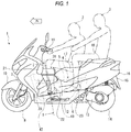
- the motorcycle 1 is what is called a scooter type, and has a body frame 4 forming the framing of the vehicle body.
- the body frame 4 has a pair of right and left upper frames 5 extending in a front and rear direction, and a pair of right and left lower frames 6 provided below the upper frames 5.
- a front fork 7 is supported on a front end portion of the body frame 4, a front wheel 8 is pivotally supported on a low end of the front fork 7, and a front fender 10 is provided so as to cover an upper side of the front wheel 8.
- a handlebar 11 is provided on an upper end of the front fork 7.
- a side stand 12 is supported on a low portion of the body frame 4.
- a front end portion of a power unit 13 is supported, a rear wheel 14 is pivotally supported on a rear end portion of the power unit 13, and a rear fender 15 is provided so as to cover an upper side of the rear wheel 14.
- the rear portion of the body frame 4 is covered with a body cover 16.
- a seat 17 on which the occupant (driver) 2 sits is provided on a rear upper side of the body frame 4, and a passenger's seat 18 on which the occupant (passenger) 3 sits is provided behind the seat 17.
- a front box 20 is provided in front of the seat 17, and a front box lid 21 is provided on a rear upper portion of the front box 20 to cover an intake port (not illustrated).
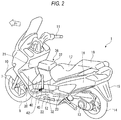
- a pair of right and left footboards 22 (only the footboard 22 on the left side is illustrated in Fig. 1 ) allowing the occupant 2 to place his or her feet is provided diagonally below and in front of the seat 17, and a pair of right and left passenger's footboards 23 (only the passenger's footboard 23 on the left side is illustrated in Fig. 1 ) allowing the occupant 3 to place his or her feet is provided behind the footboards 22.
- Each footboard 22 is inclined rearward and upward forming a low floor shape.
- Each footboard 22 is located in an intermediate portion between the seat 17 and the front box 20 in the front and rear direction, and is recessed downward in a side view with respect to the seat 17 and the front box 20.
- Each footboard 22 forms an elongated shape in the front and rear direction (see Fig. 2 ).
- each footboard 22 is constituted of a board body 24 in a plate shape and a mat 25 in a plate shape, which is overlaid on the board body 24.
- an insertion hole 26 circular in plan view is formed in a center portion in the right and left direction of the board body 24.
- an insertion trench 27 communicating with the insertion hole 26 is formed in a portion from the center portion in the right and left direction to an inside portion of the mat 25.
- the insertion trench 27 has an outside portion curved in a semicircular shape.
- a frame member 28 is provided under the board body 24, and the footboard 22 is supported on this frame member 28.
- a body side engagement member 30 is fixed detachably in an inside portion of the frame member 28.
- the body side engagement member 30 is what is called an eyebolt and has its lower portion attached to the frame member 28, and an annular engagement portion 31 is formed on its upper end.
- the engagement portion 31 is inserted in the insertion hole 26 of the board body 24 and the insertion trench 27 of the mat 25, and is located to an upper face side of the mat 25 (which also corresponds to an upper face side of the entire footboard 22).
- An upper edge of the engagement portion 31 is disposed at substantially the same height as the upper face of the mat 25 (which also corresponds to the upper face of the entire footboard 22).
- the engagement portion 31 is located in the center in the right and left direction of each footboard 22 and is located on a slightly front side of the center in the front and rear direction of each footboard 22.
- a projecting portion 32 projecting upward is provided in the center in the right and left direction of the vehicle body between the footboards 22, and the engagement portion 31 is disposed beside this projecting portion 32.
- the projecting portion 32 is supported from an under side by the pair of right and left upper frames 5, and a housing space 34 for housing a fuel tank 33 is formed below the projecting portion 32.
- a body side fastener face 35 is formed in a front portion of the projecting portion 32.
- a bag 36 as a load can be secured. This bag 36 will be described below.
- the bag 36 has a bag body 37 in which an item storage space (not illustrated) is formed, and this bag body 37 is mounted on an upper face of the projecting portion 32.
- a bag height adjusting fastener 38 is provided in an upper portion of the bag body 37.
- a pair of right and left fixing pieces 40 is attached on a front lower portion of the bag body 37.
- Each fixing piece 40 extends forward and downward, and a bag side fastener face 41 is provided on an inside face of each fixing piece 40.
- This bag side fastener face 41 is joined detachably to the body side fastener face 35 of the projecting portion 32 (see Fig. 5 ).
- Fig. 5 illustrates a state in the course of joining the bag side fastener face 41 to the body side fastener face 35.
- a fixing band 42 is attached on a front portion of each of both right and left side faces of the bag body 37.
- the fixing band 42 extends downward, and a bag side fixing member 43 is attached to a lower end of the fixing band 42.
- the bag side fixing member 43 has an attaching portion 44 clamping the lower end of the fixing band 42, a J-shaped hook portion 45 extending downward and outward from one end side of the attaching portion 44 (rear end side in this embodiment), and a fastening portion 46 having a straight bar shape provided on the other end side of the attaching portion 44 (front end side in this embodiment).
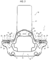
- the hook portion 45 is engaged detachably with (hooked on) the engagement portion 31 of the body side engagement member 30. As illustrated in Fig. 3 , an outside portion of the hook portion 45 is inserted in the insertion trench 27 of the mat 25. On the other hand, an inside portion of the hook portion 45 is slightly exposed to an upper side of the insertion trench 27 of the mat 25. As indicated by two-dot chain lines in Fig. 4 , the fastening portion 46 can be engaged with a free end of the hook portion 45 as necessary. That is, the bag side fixing member 43 is what is called a carabiner structure.
- the bag 36 when the bag 36 is fixed to the motorcycle 1, the bag body 37 is mounted on the projecting portion 32 of the motorcycle 1, and the hook portion 45 of each bag side fixing member 43 is engaged with (hooked on) the engagement portion 31 of each body side engagement member 30, and the bag side fastener face 41 is joined to the body side fastener face 35.
- the bag 36 is fixed at a position sandwiched by legs 49 of the occupant 2 between the seat 17 and the front box 20.
- the fixing bands 42 of the bag 36 are disposed along side faces of the projecting portion 32. Further, as illustrated in Fig. 7 , when the feet 47 of the occupant 2 are placed on the footboards 22 in a state that the bag 36 is fixed to the motorcycle 1, the engagement portions 31 and the bag side fixing members 43 are located immediately below plantar arches 48 of the feet 47 of the occupant 2 (corresponding to the vicinities of the plantar arches 48 of the feet 47 of the occupant 2). Note that if the fixing bands 42 move in this state, the hook portions 45 are locked by the feet 47 of the occupant 2 to restrict floating of the hook portions 45. Thus, a positional displacement or the like of the fixing bands 42 is difficult to occur, and the fixing state of the bag 36 can be maintained securely.
- the engagement portions 31 for fixing the bag 36 are provided on the upper face sides of the footboards 22, and thus the operator who performs an operation of mounting or dismounting the bag 36 from above can easily see the engagement portions 31, as compared to the case where the engagement portions 31 are provided on sides of the footboards 22. Thus, workability in operation of mounting or dismounting the bag 36 can be increased.
- the fixing band 42 need not be tied on the motorcycle body, and thus the operation of mounting or dismounting the bag 36 becomes much easier. Further, since the surrounding of the engagement portion 31 is guided by the board body 24, a problem of positional displacement or the like of the engagement portion 31 is difficult to occur even if the feet 47 of the occupant 2 come in contact with the engagement portion 31.
- the fixing bands 42 coupling the bag body 37 mounted on the projecting portion 32 and the bag side fixing members 43 traverse above the footboards 22. Accordingly, it is difficult for the occupant 2 to place his or her feet 47 on the footboards 22, and there is a concern that riding comfort is impaired.
- the fixing bands 42 do not traverse above the footboards 22, and there is no concern that riding comfort is impaired by the fixing bands 42.
- each engagement portions 31 be provided in a center portion in the right and left direction of the footboard 22 or provided more inside than the center portion in the right and left direction.
- each engagement portion 31 is disposed at substantially the same height as an upper face of the mat 25, and the engagement portion 31 is not exposed above the mat 25 (see Fig. 3 ). Accordingly, in the case where the engagement portions 31 are not used, or the like, the feet 47 of the occupant 2 would not be caught on the engagement portions 31, and the riding comfort of the motorcycle 1 improves. Further, since not only the engagement portion 31 but also the outside portion of the hook portion 45 of the bag side fixing member 43 is inserted in the insertion trench 27, it is difficult for the feet 47 of the occupant 2 to be caught on the bag side fixing members 43, and thus the riding comfort of the motorcycle 1 improves further.
- the engagement portions 31 are located immediately below the plantar arches 48 of the feet 47 of the occupant 2 in a state that the occupant 2 places his or her feet 47 on the footboards 22, contact of the feet 47 of the occupant 2 with the engagement portions 31 is suppressed, and it is possible to alleviate the sense of discomfort during riding. Further, in a state that the occupant 2 places his or her feet 47 on the footboards 22, not only the engagement portions 31 but also the most parts of the bag side fixing members 43 are located immediately below the plantar arches 48 of the feet 47 of the occupant 2, and hence contact of the feet 47 of the occupant 2 with the bag side fixing members 43 can be prevented. Accordingly, it is possible to further alleviate the sense of discomfort during riding.
- each engagement portion 31 is disposed in the center portion in the right and left direction of the footboard 22 has been described in this embodiment, but in another different embodiment not belonging to the invention, the engagement portion 31 may be provided in an inside end portion of each footboard 22 to make it close to the projecting portion 32, as illustrated in Fig. 8 .
- the engagement portions 31 can be made close to the projecting portion 32, and thus the fixing bands 42 run along the projecting portion 32. Accordingly, the feet 47 of the occupant 2 would not be caught on the fixing bands 42, and the bag side fixing members 43 and the engagement portions 31 are not pressed down with the feet 47, which improves the riding comfort.
- each body side engagement member 30 is fixed to the frame member 28 located under the footboard 22
- the body side engagement member 30 may be fixed to the frame member 28 located inside the projecting portion 32, thereby disposing the engagement portion 31 along the side face of the projecting portion 32. That is, "the upper face side of the footboard 22" need not always be in contact with the footboard 22 as long as it is not a lateral side or lower side of the footboard 22.
- the body side engagement member 30 is detachable from the frame member 28 in this embodiment, but in another different embodiment, the body side engagement member 30 may be non-detachable from the frame member 28.
- the case where each annular engagement portion 31 is provided on the upper end of the body side engagement member 30 to be fixed to the frame member 28 has been described in this embodiment, but in another different embodiment, the engagement portion 31 may be formed of a hook (not illustrated) to be fixed to the frame member 28, or the engagement portion 31 may be formed by deforming a part of the frame member 28.
- each footboard 22 is formed of the board body 24 and the mat 25 has been described in this embodiment, but in another different embodiment, the footboard 22 may be formed only of the board body 24. In this case, the same operation and effect as those in this embodiment can be exhibited by providing the insertion trench 27 in the upper face of the board body 24.
- the upper edge of the engagement portion 31 is disposed at substantially the same height as the upper face of the mat 25 has been described in this embodiment, but in another different embodiment not belonging to the invention, the upper edge of the engagement portion 31 may be disposed at a position lower than the upper face of the mat 25. In this case, catching of the foot 47 of the occupant 2 on the engagement portion 31 can be prevented more effectively.
- the insertion trench 27 be covered with a cover (not illustrated) which covers the engagement portion 31.
- a cover which covers the engagement portion 31.
- the engagement portion 31 can be hidden when not in use, which improves its appearance, and clogging of foreign matters such as sands or dirt in the insertion hole 26 or the insertion trench 27 is prevented, which improves component durability.
- the above-described cover be formed integrally with the mat 25, and by employing such a structure, losing of the cover can be prevented.
- a load such as a bag may be fixed to the motorcycle 1 by using only the hook mechanism.
- the structure of the present invention may be applied to another different straddle type vehicle such as an electric wheel chair, an off-road traveling vehicle, a personal water craft, or the like.
- the present invention it is possible to increase workability in operation of mounting or dismounting a load on a vehicle body of a straddle type vehicle, by making the engagement portions for fixing a load easily viewable.
Landscapes
- Engineering & Computer Science (AREA)
- Mechanical Engineering (AREA)
- Automatic Cycles, And Cycles In General (AREA)
Claims (2)
- Fahrzeug (1) vom Grätschsitztyp umfassend einen Sitz (17) auf dem ein Benutzer sitzen kann,
ein Paar rechter und linker Trittbretter (22), die in einer Seitenansicht der Karoserie diagonal unter und vordem Sitz (17) ausgebildet sind und es dem Benutzer erlauben seine oder ihre Füße darauf zu platzieren, ein vorstehender Teil (32), der zwischen den Trittbrettern (22) angeordnet ist und nach oben übersteht,
ein Paar rechter und linker Eingreifteile (31) zur Befestigung einer auf dem vorstehenden Teil (32) montierten Last (36) die auf einer Oberseite des Paars an Trittbrettern (22) angeordnet ist,
dadurch gekennzeichnet, dass
ein Paar an rechten und linken Einführlöchern (26), in welchen die Eingreifteile (31) eingeführt werden, die in einem zentralen Bereich in der Rechts-Links-Richtung der Fußtritte (22) ausgebildet sind, wobei
ein Paar rechter und linker Einführschlitze (27), die mit den Einführlöchern (26) kommunizieren und in die die Eingreifteile (31) eingeführt werden, sind in einem von dem zentralen in der Rechts-Links-Richtung zu einem inneren Bereich ausgebildeten Teil der Oberseite der Fußtritte (22) ausgebildet, und
Oberkanten der Eingreifteile (31) sind in derselben Höhe wie die Oberseiten der Fußtritte (22) angeordnet. - Fahrzeug (1) vom Grätschsitztyp nach Anspruch 1, wobei jeder der Eingreifteile (31) ausgebildet ist, um in der Umgebung des Fußsohlenbogens des Benutzers in einem Zustand, in dem der Benutzer den Fuß auf den Fußtritt (22) platziert, angeordnet zu sein.
Applications Claiming Priority (1)
| Application Number | Priority Date | Filing Date | Title |
|---|---|---|---|
| JP2012086046A JP2013216130A (ja) | 2012-04-05 | 2012-04-05 | 鞍乗型車両 |
Publications (2)
| Publication Number | Publication Date |
|---|---|
| EP2647558A1 EP2647558A1 (de) | 2013-10-09 |
| EP2647558B1 true EP2647558B1 (de) | 2017-03-15 |
Family
ID=48049838
Family Applications (1)
| Application Number | Title | Priority Date | Filing Date |
|---|---|---|---|
| EP13162313.4A Not-in-force EP2647558B1 (de) | 2012-04-05 | 2013-04-04 | Grätschsitz-Fahrzeug |
Country Status (4)
| Country | Link |
|---|---|
| US (1) | US9346506B2 (de) |
| EP (1) | EP2647558B1 (de) |
| JP (1) | JP2013216130A (de) |
| ES (1) | ES2621755T3 (de) |
Families Citing this family (6)
| Publication number | Priority date | Publication date | Assignee | Title |
|---|---|---|---|---|
| US8888162B2 (en) * | 2012-10-24 | 2014-11-18 | Vectrix International Limited | Universal accessory mounting system for two-wheeled and three-wheeled vehicles |
| JP6208698B2 (ja) * | 2015-01-23 | 2017-10-04 | 本田技研工業株式会社 | 鞍乗り型車両の収納部構造 |
| CN105599837A (zh) * | 2015-12-31 | 2016-05-25 | 天然善德(天津)科技发展有限公司 | 一种自行车 |
| JP2019026049A (ja) * | 2017-07-28 | 2019-02-21 | ヤマハ発動機株式会社 | アンダーボーン型車両 |
| JP2023051180A (ja) * | 2021-09-30 | 2023-04-11 | ヤマハ発動機株式会社 | 鞍乗型車両 |
| JP2023067220A (ja) * | 2021-10-29 | 2023-05-16 | ヤマハ発動機株式会社 | 鞍乗型車両 |
Family Cites Families (13)
| Publication number | Priority date | Publication date | Assignee | Title |
|---|---|---|---|---|
| JPS6032183U (ja) | 1983-08-11 | 1985-03-05 | 株式会社 タカイシ | タンクバッグ用マット |
| JPS645671Y2 (de) * | 1984-09-25 | 1989-02-13 | ||
| JPS6231344A (ja) | 1985-08-01 | 1987-02-10 | Matsushita Electric Ind Co Ltd | 小型モ−タ |
| US4830134A (en) * | 1986-07-29 | 1989-05-16 | Honda Giken Kogyo Kabushiki Kaisha | Motorcycle storage container mounting system |
| JPH02158468A (ja) | 1988-12-13 | 1990-06-18 | Y Ii C:Kk | スクータ形車両の物品運搬装置 |
| JP3362514B2 (ja) * | 1994-08-03 | 2003-01-07 | スズキ株式会社 | 自動二輪車の荷物搭載装置 |
| ITMI20040711A1 (it) * | 2004-04-09 | 2004-07-09 | Piaggio & C Spa | Vano portaoggetti e-o portacaschi per motoveicoli |
| JP3676798B2 (ja) * | 2004-07-12 | 2005-07-27 | 本田技研工業株式会社 | スクータ型車両の車体構造 |
| US7114739B2 (en) * | 2005-02-15 | 2006-10-03 | Colano Richard V | Adjustable passenger floorboards |
| JP4531652B2 (ja) * | 2005-07-29 | 2010-08-25 | 本田技研工業株式会社 | 低床式車両 |
| JP4566856B2 (ja) * | 2005-08-01 | 2010-10-20 | 本田技研工業株式会社 | 低床式車両の荷物固定部構造 |
| JP4939255B2 (ja) * | 2007-02-22 | 2012-05-23 | 本田技研工業株式会社 | 自動二輪車の前部車体カバー構造 |
| US7914014B1 (en) * | 2009-09-24 | 2011-03-29 | Floyd Henry Robinson | Scooter footbelt |
-
2012
- 2012-04-05 JP JP2012086046A patent/JP2013216130A/ja active Pending
-
2013
- 2013-04-04 EP EP13162313.4A patent/EP2647558B1/de not_active Not-in-force
- 2013-04-04 ES ES13162313.4T patent/ES2621755T3/es active Active
- 2013-04-05 US US13/857,350 patent/US9346506B2/en not_active Expired - Fee Related
Non-Patent Citations (1)
| Title |
|---|
| None * |
Also Published As
| Publication number | Publication date |
|---|---|
| JP2013216130A (ja) | 2013-10-24 |
| US20130264368A1 (en) | 2013-10-10 |
| US9346506B2 (en) | 2016-05-24 |
| ES2621755T3 (es) | 2017-07-05 |
| EP2647558A1 (de) | 2013-10-09 |
Similar Documents
| Publication | Publication Date | Title |
|---|---|---|
| US9346506B2 (en) | Straddle type vehicle | |
| JP5718698B2 (ja) | 鞍乗型車両のシート構造 | |
| US10131395B2 (en) | Tank cover structure for motorcycle | |
| US9434436B1 (en) | Rear structure for saddle-ride type vehicle | |
| JP5963206B2 (ja) | 鞍乗り型車両のシート支持構造 | |
| EP2447138B1 (de) | Rückseitenstruktur für Sattelfahrzeuge | |
| JP2013189171A (ja) | 鞍乗型車両の吸気構造 | |
| JP5658882B2 (ja) | 自動二輪車の後部構造 | |
| WO2015015610A1 (ja) | 自動二輪車のボディカバー構造 | |
| CN102582727B (zh) | 跨骑型车辆的踏板构造 | |
| JP2002211468A (ja) | スクータ型自動二輪車のフレーム構造 | |
| JPH11129953A (ja) | 自転車用小児同乗席 | |
| JP2006240345A (ja) | 自動二輪車のシートフレーム | |
| JP2009107566A (ja) | 自動二輪車 | |
| JP2004306750A (ja) | 鞍乗り型車両のステップボード | |
| JP4088865B2 (ja) | スクータ型自動二輪車 | |
| JP5749482B2 (ja) | 跨座式車両 | |
| JP5858369B2 (ja) | 鞍乗り型車両 | |
| JP5005591B2 (ja) | 自動二輪車におけるグラブレール構造 | |
| JP2000025671A (ja) | スクータ型車両のフロントフェンダ構造 | |
| JP6279445B2 (ja) | 鞍乗り型車両 | |
| JP6363801B2 (ja) | 自動二輪車用シート支持フレーム構造 | |
| JP6351172B2 (ja) | 車体後部構造 | |
| JP5831052B2 (ja) | 小型電動車両 | |
| JP5010942B2 (ja) | スクータ型車両 |
Legal Events
| Date | Code | Title | Description |
|---|---|---|---|
| PUAI | Public reference made under article 153(3) epc to a published international application that has entered the european phase |
Free format text: ORIGINAL CODE: 0009012 |
|
| AK | Designated contracting states |
Kind code of ref document: A1 Designated state(s): AL AT BE BG CH CY CZ DE DK EE ES FI FR GB GR HR HU IE IS IT LI LT LU LV MC MK MT NL NO PL PT RO RS SE SI SK SM TR |
|
| AX | Request for extension of the european patent |
Extension state: BA ME |
|
| 17P | Request for examination filed |
Effective date: 20140225 |
|
| RBV | Designated contracting states (corrected) |
Designated state(s): AL AT BE BG CH CY CZ DE DK EE ES FI FR GB GR HR HU IE IS IT LI LT LU LV MC MK MT NL NO PL PT RO RS SE SI SK SM TR |
|
| 17Q | First examination report despatched |
Effective date: 20150320 |
|
| GRAP | Despatch of communication of intention to grant a patent |
Free format text: ORIGINAL CODE: EPIDOSNIGR1 |
|
| INTG | Intention to grant announced |
Effective date: 20160927 |
|
| STAA | Information on the status of an ep patent application or granted ep patent |
Free format text: STATUS: GRANT OF PATENT IS INTENDED |
|
| GRAS | Grant fee paid |
Free format text: ORIGINAL CODE: EPIDOSNIGR3 |
|
| GRAA | (expected) grant |
Free format text: ORIGINAL CODE: 0009210 |
|
| STAA | Information on the status of an ep patent application or granted ep patent |
Free format text: STATUS: THE PATENT HAS BEEN GRANTED |
|
| AK | Designated contracting states |
Kind code of ref document: B1 Designated state(s): AL AT BE BG CH CY CZ DE DK EE ES FI FR GB GR HR HU IE IS IT LI LT LU LV MC MK MT NL NO PL PT RO RS SE SI SK SM TR |
|
| REG | Reference to a national code |
Ref country code: CH Ref legal event code: EP Ref country code: GB Ref legal event code: FG4D |
|
| REG | Reference to a national code |
Ref country code: IE Ref legal event code: FG4D |
|
| REG | Reference to a national code |
Ref country code: AT Ref legal event code: REF Ref document number: 875224 Country of ref document: AT Kind code of ref document: T Effective date: 20170415 |
|
| REG | Reference to a national code |
Ref country code: DE Ref legal event code: R096 Ref document number: 602013018480 Country of ref document: DE |
|
| REG | Reference to a national code |
Ref country code: ES Ref legal event code: FG2A Ref document number: 2621755 Country of ref document: ES Kind code of ref document: T3 Effective date: 20170705 |
|
| REG | Reference to a national code |
Ref country code: NL Ref legal event code: MP Effective date: 20170315 |
|
| REG | Reference to a national code |
Ref country code: LT Ref legal event code: MG4D |
|
| PG25 | Lapsed in a contracting state [announced via postgrant information from national office to epo] |
Ref country code: LT Free format text: LAPSE BECAUSE OF FAILURE TO SUBMIT A TRANSLATION OF THE DESCRIPTION OR TO PAY THE FEE WITHIN THE PRESCRIBED TIME-LIMIT Effective date: 20170315 Ref country code: HR Free format text: LAPSE BECAUSE OF FAILURE TO SUBMIT A TRANSLATION OF THE DESCRIPTION OR TO PAY THE FEE WITHIN THE PRESCRIBED TIME-LIMIT Effective date: 20170315 Ref country code: NO Free format text: LAPSE BECAUSE OF FAILURE TO SUBMIT A TRANSLATION OF THE DESCRIPTION OR TO PAY THE FEE WITHIN THE PRESCRIBED TIME-LIMIT Effective date: 20170615 Ref country code: GR Free format text: LAPSE BECAUSE OF FAILURE TO SUBMIT A TRANSLATION OF THE DESCRIPTION OR TO PAY THE FEE WITHIN THE PRESCRIBED TIME-LIMIT Effective date: 20170616 Ref country code: FI Free format text: LAPSE BECAUSE OF FAILURE TO SUBMIT A TRANSLATION OF THE DESCRIPTION OR TO PAY THE FEE WITHIN THE PRESCRIBED TIME-LIMIT Effective date: 20170315 |
|
| REG | Reference to a national code |
Ref country code: AT Ref legal event code: MK05 Ref document number: 875224 Country of ref document: AT Kind code of ref document: T Effective date: 20170315 |
|
| PG25 | Lapsed in a contracting state [announced via postgrant information from national office to epo] |
Ref country code: SE Free format text: LAPSE BECAUSE OF FAILURE TO SUBMIT A TRANSLATION OF THE DESCRIPTION OR TO PAY THE FEE WITHIN THE PRESCRIBED TIME-LIMIT Effective date: 20170315 Ref country code: LV Free format text: LAPSE BECAUSE OF FAILURE TO SUBMIT A TRANSLATION OF THE DESCRIPTION OR TO PAY THE FEE WITHIN THE PRESCRIBED TIME-LIMIT Effective date: 20170315 Ref country code: RS Free format text: LAPSE BECAUSE OF FAILURE TO SUBMIT A TRANSLATION OF THE DESCRIPTION OR TO PAY THE FEE WITHIN THE PRESCRIBED TIME-LIMIT Effective date: 20170315 Ref country code: BG Free format text: LAPSE BECAUSE OF FAILURE TO SUBMIT A TRANSLATION OF THE DESCRIPTION OR TO PAY THE FEE WITHIN THE PRESCRIBED TIME-LIMIT Effective date: 20170615 |
|
| PG25 | Lapsed in a contracting state [announced via postgrant information from national office to epo] |
Ref country code: NL Free format text: LAPSE BECAUSE OF FAILURE TO SUBMIT A TRANSLATION OF THE DESCRIPTION OR TO PAY THE FEE WITHIN THE PRESCRIBED TIME-LIMIT Effective date: 20170315 |
|
| PG25 | Lapsed in a contracting state [announced via postgrant information from national office to epo] |
Ref country code: SK Free format text: LAPSE BECAUSE OF FAILURE TO SUBMIT A TRANSLATION OF THE DESCRIPTION OR TO PAY THE FEE WITHIN THE PRESCRIBED TIME-LIMIT Effective date: 20170315 Ref country code: RO Free format text: LAPSE BECAUSE OF FAILURE TO SUBMIT A TRANSLATION OF THE DESCRIPTION OR TO PAY THE FEE WITHIN THE PRESCRIBED TIME-LIMIT Effective date: 20170315 Ref country code: CZ Free format text: LAPSE BECAUSE OF FAILURE TO SUBMIT A TRANSLATION OF THE DESCRIPTION OR TO PAY THE FEE WITHIN THE PRESCRIBED TIME-LIMIT Effective date: 20170315 Ref country code: AT Free format text: LAPSE BECAUSE OF FAILURE TO SUBMIT A TRANSLATION OF THE DESCRIPTION OR TO PAY THE FEE WITHIN THE PRESCRIBED TIME-LIMIT Effective date: 20170315 Ref country code: EE Free format text: LAPSE BECAUSE OF FAILURE TO SUBMIT A TRANSLATION OF THE DESCRIPTION OR TO PAY THE FEE WITHIN THE PRESCRIBED TIME-LIMIT Effective date: 20170315 |
|
| REG | Reference to a national code |
Ref country code: DE Ref legal event code: R119 Ref document number: 602013018480 Country of ref document: DE |
|
| PG25 | Lapsed in a contracting state [announced via postgrant information from national office to epo] |
Ref country code: PT Free format text: LAPSE BECAUSE OF FAILURE TO SUBMIT A TRANSLATION OF THE DESCRIPTION OR TO PAY THE FEE WITHIN THE PRESCRIBED TIME-LIMIT Effective date: 20170717 Ref country code: PL Free format text: LAPSE BECAUSE OF FAILURE TO SUBMIT A TRANSLATION OF THE DESCRIPTION OR TO PAY THE FEE WITHIN THE PRESCRIBED TIME-LIMIT Effective date: 20170315 Ref country code: IS Free format text: LAPSE BECAUSE OF FAILURE TO SUBMIT A TRANSLATION OF THE DESCRIPTION OR TO PAY THE FEE WITHIN THE PRESCRIBED TIME-LIMIT Effective date: 20170715 Ref country code: SM Free format text: LAPSE BECAUSE OF FAILURE TO SUBMIT A TRANSLATION OF THE DESCRIPTION OR TO PAY THE FEE WITHIN THE PRESCRIBED TIME-LIMIT Effective date: 20170315 |
|
| REG | Reference to a national code |
Ref country code: CH Ref legal event code: PL |
|
| PLBE | No opposition filed within time limit |
Free format text: ORIGINAL CODE: 0009261 |
|
| STAA | Information on the status of an ep patent application or granted ep patent |
Free format text: STATUS: NO OPPOSITION FILED WITHIN TIME LIMIT |
|
| REG | Reference to a national code |
Ref country code: IE Ref legal event code: MM4A |
|
| REG | Reference to a national code |
Ref country code: FR Ref legal event code: ST Effective date: 20171229 |
|
| PG25 | Lapsed in a contracting state [announced via postgrant information from national office to epo] |
Ref country code: MC Free format text: LAPSE BECAUSE OF FAILURE TO SUBMIT A TRANSLATION OF THE DESCRIPTION OR TO PAY THE FEE WITHIN THE PRESCRIBED TIME-LIMIT Effective date: 20170315 Ref country code: FR Free format text: LAPSE BECAUSE OF NON-PAYMENT OF DUE FEES Effective date: 20170515 Ref country code: DK Free format text: LAPSE BECAUSE OF FAILURE TO SUBMIT A TRANSLATION OF THE DESCRIPTION OR TO PAY THE FEE WITHIN THE PRESCRIBED TIME-LIMIT Effective date: 20170315 Ref country code: DE Free format text: LAPSE BECAUSE OF NON-PAYMENT OF DUE FEES Effective date: 20171103 |
|
| 26N | No opposition filed |
Effective date: 20171218 |
|
| GBPC | Gb: european patent ceased through non-payment of renewal fee |
Effective date: 20170615 |
|
| PG25 | Lapsed in a contracting state [announced via postgrant information from national office to epo] |
Ref country code: LI Free format text: LAPSE BECAUSE OF NON-PAYMENT OF DUE FEES Effective date: 20170430 Ref country code: CH Free format text: LAPSE BECAUSE OF NON-PAYMENT OF DUE FEES Effective date: 20170430 Ref country code: SI Free format text: LAPSE BECAUSE OF FAILURE TO SUBMIT A TRANSLATION OF THE DESCRIPTION OR TO PAY THE FEE WITHIN THE PRESCRIBED TIME-LIMIT Effective date: 20170315 Ref country code: LU Free format text: LAPSE BECAUSE OF NON-PAYMENT OF DUE FEES Effective date: 20170404 |
|
| REG | Reference to a national code |
Ref country code: BE Ref legal event code: MM Effective date: 20170430 |
|
| PG25 | Lapsed in a contracting state [announced via postgrant information from national office to epo] |
Ref country code: GB Free format text: LAPSE BECAUSE OF NON-PAYMENT OF DUE FEES Effective date: 20170615 Ref country code: IE Free format text: LAPSE BECAUSE OF NON-PAYMENT OF DUE FEES Effective date: 20170404 |
|
| PG25 | Lapsed in a contracting state [announced via postgrant information from national office to epo] |
Ref country code: BE Free format text: LAPSE BECAUSE OF NON-PAYMENT OF DUE FEES Effective date: 20170430 |
|
| PG25 | Lapsed in a contracting state [announced via postgrant information from national office to epo] |
Ref country code: MT Free format text: LAPSE BECAUSE OF NON-PAYMENT OF DUE FEES Effective date: 20170404 |
|
| PG25 | Lapsed in a contracting state [announced via postgrant information from national office to epo] |
Ref country code: HU Free format text: LAPSE BECAUSE OF FAILURE TO SUBMIT A TRANSLATION OF THE DESCRIPTION OR TO PAY THE FEE WITHIN THE PRESCRIBED TIME-LIMIT; INVALID AB INITIO Effective date: 20130404 |
|
| PG25 | Lapsed in a contracting state [announced via postgrant information from national office to epo] |
Ref country code: CY Free format text: LAPSE BECAUSE OF NON-PAYMENT OF DUE FEES Effective date: 20170315 |
|
| PG25 | Lapsed in a contracting state [announced via postgrant information from national office to epo] |
Ref country code: MK Free format text: LAPSE BECAUSE OF FAILURE TO SUBMIT A TRANSLATION OF THE DESCRIPTION OR TO PAY THE FEE WITHIN THE PRESCRIBED TIME-LIMIT Effective date: 20170315 |
|
| PG25 | Lapsed in a contracting state [announced via postgrant information from national office to epo] |
Ref country code: TR Free format text: LAPSE BECAUSE OF FAILURE TO SUBMIT A TRANSLATION OF THE DESCRIPTION OR TO PAY THE FEE WITHIN THE PRESCRIBED TIME-LIMIT Effective date: 20170315 |
|
| PG25 | Lapsed in a contracting state [announced via postgrant information from national office to epo] |
Ref country code: AL Free format text: LAPSE BECAUSE OF FAILURE TO SUBMIT A TRANSLATION OF THE DESCRIPTION OR TO PAY THE FEE WITHIN THE PRESCRIBED TIME-LIMIT Effective date: 20170315 |
|
| PGFP | Annual fee paid to national office [announced via postgrant information from national office to epo] |
Ref country code: IT Payment date: 20220310 Year of fee payment: 10 |
|
| PGFP | Annual fee paid to national office [announced via postgrant information from national office to epo] |
Ref country code: ES Payment date: 20220504 Year of fee payment: 10 |
|
| PG25 | Lapsed in a contracting state [announced via postgrant information from national office to epo] |
Ref country code: IT Free format text: LAPSE BECAUSE OF NON-PAYMENT OF DUE FEES Effective date: 20230404 |
|
| REG | Reference to a national code |
Ref country code: ES Ref legal event code: FD2A Effective date: 20240531 |
|
| PG25 | Lapsed in a contracting state [announced via postgrant information from national office to epo] |
Ref country code: ES Free format text: LAPSE BECAUSE OF NON-PAYMENT OF DUE FEES Effective date: 20230405 |
|
| PG25 | Lapsed in a contracting state [announced via postgrant information from national office to epo] |
Ref country code: ES Free format text: LAPSE BECAUSE OF NON-PAYMENT OF DUE FEES Effective date: 20230405 |