EP2644541A1 - Vorrichtung zum zuführen geschnittener papierbögen - Google Patents
Vorrichtung zum zuführen geschnittener papierbögen Download PDFInfo
- Publication number
- EP2644541A1 EP2644541A1 EP12742565.0A EP12742565A EP2644541A1 EP 2644541 A1 EP2644541 A1 EP 2644541A1 EP 12742565 A EP12742565 A EP 12742565A EP 2644541 A1 EP2644541 A1 EP 2644541A1
- Authority
- EP
- European Patent Office
- Prior art keywords
- cut
- belt
- contact amount
- amount adjuster
- sheet
- Prior art date
- Legal status (The legal status is an assumption and is not a legal conclusion. Google has not performed a legal analysis and makes no representation as to the accuracy of the status listed.)
- Granted
Links
Images











Classifications
-
- B—PERFORMING OPERATIONS; TRANSPORTING
- B65—CONVEYING; PACKING; STORING; HANDLING THIN OR FILAMENTARY MATERIAL
- B65H—HANDLING THIN OR FILAMENTARY MATERIAL, e.g. SHEETS, WEBS, CABLES
- B65H3/00—Separating articles from piles
- B65H3/02—Separating articles from piles using friction forces between articles and separator
- B65H3/04—Endless-belt separators
- B65H3/042—Endless-belt separators separating from the bottom of the pile
-
- B—PERFORMING OPERATIONS; TRANSPORTING
- B65—CONVEYING; PACKING; STORING; HANDLING THIN OR FILAMENTARY MATERIAL
- B65H—HANDLING THIN OR FILAMENTARY MATERIAL, e.g. SHEETS, WEBS, CABLES
- B65H1/00—Supports or magazines for piles from which articles are to be separated
- B65H1/04—Supports or magazines for piles from which articles are to be separated adapted to support articles substantially horizontally, e.g. for separation from top of pile
- B65H1/06—Supports or magazines for piles from which articles are to be separated adapted to support articles substantially horizontally, e.g. for separation from top of pile for separation from bottom of pile
-
- B—PERFORMING OPERATIONS; TRANSPORTING
- B65—CONVEYING; PACKING; STORING; HANDLING THIN OR FILAMENTARY MATERIAL
- B65H—HANDLING THIN OR FILAMENTARY MATERIAL, e.g. SHEETS, WEBS, CABLES
- B65H3/00—Separating articles from piles
- B65H3/02—Separating articles from piles using friction forces between articles and separator
- B65H3/04—Endless-belt separators
-
- B—PERFORMING OPERATIONS; TRANSPORTING
- B65—CONVEYING; PACKING; STORING; HANDLING THIN OR FILAMENTARY MATERIAL
- B65H—HANDLING THIN OR FILAMENTARY MATERIAL, e.g. SHEETS, WEBS, CABLES
- B65H3/00—Separating articles from piles
- B65H3/46—Supplementary devices or measures to assist separation or prevent double feed
- B65H3/54—Pressing or holding devices
-
- B—PERFORMING OPERATIONS; TRANSPORTING
- B65—CONVEYING; PACKING; STORING; HANDLING THIN OR FILAMENTARY MATERIAL
- B65H—HANDLING THIN OR FILAMENTARY MATERIAL, e.g. SHEETS, WEBS, CABLES
- B65H3/00—Separating articles from piles
- B65H3/46—Supplementary devices or measures to assist separation or prevent double feed
- B65H3/56—Elements, e.g. scrapers, fingers, needles, brushes, acting on separated article or on edge of the pile
-
- B—PERFORMING OPERATIONS; TRANSPORTING
- B65—CONVEYING; PACKING; STORING; HANDLING THIN OR FILAMENTARY MATERIAL
- B65H—HANDLING THIN OR FILAMENTARY MATERIAL, e.g. SHEETS, WEBS, CABLES
- B65H3/00—Separating articles from piles
- B65H3/66—Article guides or smoothers, e.g. movable in operation
- B65H3/68—Article guides or smoothers, e.g. movable in operation immovable in operation
-
- B—PERFORMING OPERATIONS; TRANSPORTING
- B65—CONVEYING; PACKING; STORING; HANDLING THIN OR FILAMENTARY MATERIAL
- B65H—HANDLING THIN OR FILAMENTARY MATERIAL, e.g. SHEETS, WEBS, CABLES
- B65H9/00—Registering, e.g. orientating, articles; Devices therefor
- B65H9/10—Pusher and like movable registers; Pusher or gripper devices which move articles into registered position
- B65H9/101—Pusher and like movable registers; Pusher or gripper devices which move articles into registered position acting on the edge of the article
-
- B—PERFORMING OPERATIONS; TRANSPORTING
- B65—CONVEYING; PACKING; STORING; HANDLING THIN OR FILAMENTARY MATERIAL
- B65H—HANDLING THIN OR FILAMENTARY MATERIAL, e.g. SHEETS, WEBS, CABLES
- B65H2405/00—Parts for holding the handled material
- B65H2405/10—Cassettes, holders, bins, decks, trays, supports or magazines for sheets stacked substantially horizontally
- B65H2405/11—Parts and details thereof
- B65H2405/111—Bottom
- B65H2405/1115—Bottom with surface inclined, e.g. in width-wise direction
- B65H2405/11152—Bottom with surface inclined, e.g. in width-wise direction with surface inclined downwardly in transport direction
-
- B—PERFORMING OPERATIONS; TRANSPORTING
- B65—CONVEYING; PACKING; STORING; HANDLING THIN OR FILAMENTARY MATERIAL
- B65H—HANDLING THIN OR FILAMENTARY MATERIAL, e.g. SHEETS, WEBS, CABLES
- B65H2405/00—Parts for holding the handled material
- B65H2405/10—Cassettes, holders, bins, decks, trays, supports or magazines for sheets stacked substantially horizontally
- B65H2405/11—Parts and details thereof
- B65H2405/112—Rear, i.e. portion opposite to the feeding / delivering side
- B65H2405/1122—Rear, i.e. portion opposite to the feeding / delivering side movable linearly, details therefor
-
- B—PERFORMING OPERATIONS; TRANSPORTING
- B65—CONVEYING; PACKING; STORING; HANDLING THIN OR FILAMENTARY MATERIAL
- B65H—HANDLING THIN OR FILAMENTARY MATERIAL, e.g. SHEETS, WEBS, CABLES
- B65H2405/00—Parts for holding the handled material
- B65H2405/10—Cassettes, holders, bins, decks, trays, supports or magazines for sheets stacked substantially horizontally
- B65H2405/11—Parts and details thereof
- B65H2405/112—Rear, i.e. portion opposite to the feeding / delivering side
- B65H2405/1124—Rear, i.e. portion opposite to the feeding / delivering side pivotable, details therefor
Definitions
- the present invention relates to a cut-sheet feeder which sequentially draws and feeds a cut sheet from a stack of cut sheets with one placed on another.
- a cut-sheet feeder of this type is one which brings a feed belt into rotational contact with the lower end of a stack of cut sheets while the rear end portion of the stack of cut sheets is being lifted up by an inclined guide member having a frontward inclined upper surface (e.g., Patent Document 1).
- the present invention was developed in view of the aforementioned problem. It is therefore an object of the invention to provide a cut-sheet feeder which is capable of reducing the occurrence of partial double feeding than the conventional ones.
- the inventor of the present application figured out the mechanism of partial double feeding which had not been clarified in the past. That is, as the lowermost cut sheet in a stack of cut sheets (hereinafter to be referred to as the "first cut sheet”) is drawn by a feed belt, the contact area between the cut sheet next to the first cut sheet (hereinafter to be referred to as the "second cut sheet”) and the feed belt increases. This causes an increase in the kinetic friction force which the second cut sheet receives from the feed belt. Then, partial double feeding occurs when the kinetic friction force acting between the second cut sheet and the feed belt becomes greater than the static friction force acting between the second cut sheet and the cut sheet next to the second cut sheet before the first cut sheet is completely drawn.
- the contact area between the second cut sheet and the feed belt is set so that the kinetic friction force acting between the second cut sheet and the feed belt becomes greater than the static friction force acting between the second cut sheet and the cut sheet next to the second cut sheet when the first cut sheet is completely drawn, it is made possible to prevent the so-called partial double feeding in which the second cut sheet starts to be fed before the first cut sheet is completely drawn, so that the cut sheets partially overlap each other when being fed.
- the inventor of the present application has reached the finding that another member can be provided separately from the inclined guide member in order to adjust the contact area between the cut sheet and the feed belt, thereby reducing the occurrence of partial double feeding or easily resolving the partial double feeding even in the case of occurrence of the partial double feeding.
- This finding has led to the inventions according to claims 1 to 10 as described below.
- the cut-sheet feeder according to the invention of claim 1 brings a feed belt into rotational contact with the lowermost cut sheet of a stack of cut sheets, one stacked on another, and draws and feeds the lowermost cut sheet sequentially from the stack of cut sheets in the forward direction of feeding of cut sheets.
- the cut-sheet feeder includes a belt contact amount adjuster disposed below the stack of cut sheets, and while a rear portion of the lowermost cut sheet of the stack of cut sheets from an intermediate position in the direction of feeding of cut sheets is lifted off the feed belt, supporting a front portion from the intermediate position rotationally contactably with the feed belt.
- the cut-sheet feeder further includes an inclined guide member disposed below the rear end portion of the stack of cut sheets and protruded above the belt contact amount adjuster.
- the inclined guide member also has a guide surface which is inclined forwardly downward and which shifts the plurality of cut sheets included in the stack of cut sheets along the guide surface in the direction of feeding of cut sheets.
- the cut-sheet feeder also includes an inclined guide member variable support mechanism capable of moving and fixing the inclined guide member at a given position in the direction of feeding of cut sheets, and a belt contact amount adjusting mechanism capable of moving separately from the inclined guide member and of fixing the belt contact amount adjuster at a given position in the direction of feeding of cut sheets.
- the invention of claim 2 is the cut-sheet feeder according to claim 1, which includes a hand-over inclined surface inclined forwardly downward and formed at the front end portion of a section of the upper surface of the belt contact amount adjuster, where the section is located above the rotational contact surface of the feed belt with the cut sheet.
- the invention of claim 3 is the cut-sheet feeder according to claim 2, which includes a cut-sheet main support surface formed on a section of the upper surface of the belt contact amount adjuster and formed at a smaller angle of inclination with respect to a horizontal plane than the hand-over inclined surface, where the section is more rearward than the hand-over inclined surface.
- the invention of claim 4 is the cut-sheet feeder according to claim 1, wherein the belt contact amount adjuster is configured such that the entirety of a section to be brought into contact with the stack of cut sheets is a flat surface which is inclined forwardly downward.
- the invention of claim 5 is the cut-sheet feeder according to any one of claims 1 to 4, which includes a hand-over projection provided on the belt contact amount adjuster and disposed to a side of the feed belt.
- the hand-over projection is inclined such that the upper surface of a front end portion is located below a rotational contact surface of the feed belt with the cut sheet and the upper surface of a rear end portion is located above the rotational contact surface.
- the cut-sheet feeder further includes a hand-over section configured to have the hand-over projection disposed between a pair of the feed belts or to have the feed belt disposed between a pair of the hand-over projections.
- the invention of claim 6 is the cut-sheet feeder according to claim 5, wherein the belt contact amount adjuster has a cover section to cover the feed belt from above and has the hand-over projection protruded from the front end of the cover section.
- the invention of claim 7 is the cut-sheet feeder according to any one of claims 1 to 6, wherein the belt contact amount adjustingmechanism includes a first guide for supporting the belt contact amount adjuster linearly movably in the direction of feeding of cut sheets, and a first fixing part capable of fixing the belt contact amount adjuster at a given position along the first guide.
- the invention of claim 8 is the cut-sheet feeder according to claim 7, wherein the first fixing part includes the following: a plurality of first locking sections formed along the longitudinal direction of the first guide; a first locking pawl provided on the belt contact amount adjuster and being capable of reciprocating between a first locking position at which the first locking pawl is locked with a given one of the first locking sections and a first release position at which the engagement with the first locking section is released; and a first spring for retaining the first locking pawl at the first locking position.
- the invention of claim 9 is the cut-sheet feeder according to any one of claims 1 to 8, wherein the inclined guide member variable support mechanism includes the following: a second guide for supporting the inclined guide member linearly movably in the direction of feeding of cut sheets; and a second fixing part capable of fixing the inclined guide member at a given position along the second guide.
- the invention of claim 10 is the cut-sheet feeder according to claim 9, wherein the second fixing part includes the following: a plurality of second locking sections formed along the longitudinal direction of the second guide; a second locking pawl provided on the inclined guide member and being capable of reciprocating between a second locking position at which the second locking pawl is locked with a given one of the second locking sections and a second release position at which the engagement with the second locking section is released; and a second spring for retaining the second locking pawl at the second locking position.
- the cut-sheet feeder according to the invention of claim 1 includes the belt contact amount adjuster which allows a rear portion of the lowermost cut sheet of the stack of cut sheets from an intermediate position in the direction of feeding of cut sheets to be lifted off the feed belt and which allows a front portion from the intermediate position to be supported in rotational contact with the feed belt. Furthermore, the belt contact amount adjusting mechanism is capable of varying the position of the belt contact amount adjuster in the direction of feeding of cut sheets so as to adjust the contact area between the feedbelt and the stack of cut sheets. This makes it possible to reduce the occurrence of partial double feeding than before.
- the inclined guide member can be varied in the direction of feeding of cut sheets, it is possible to accommodate changes in the size of the cut sheets.
- the present invention allows the positions of the belt contact amount adjuster and the inclined guide member to be varied separately, the contact area between the stack of cut sheets and the feed belt can be varied with the inclined guide member kept fixed at a position depending on the size of the cut sheets.
- the belt contact amount adjuster may also be made up of a horizontal flat plate, or alternatively, as in the invention of claim 2, may be adapted such that the hand-over inclined surface inclined forwardly downward is formed at the front end portion of a section of the upper surface of the belt contact amount adjuster, the section being located above the rotational contact surface of the feed belt with the cut sheet.
- the configuration of the invention of claim 2 when the cut sheet is drawn from the stack of cut sheets, it is possible to smoothly hand over the rear portion of the cut sheet supported by the belt contact amount adjuster to the feed belt.
- the belt contact amount adjuster may be adapted such that the upper surface of a section more rearward than the hand-over inclined surface may have a smaller angle of inclination with respect to a horizontal plane than the hand-over inclined surface (the invention of claim 3).
- the belt contact amount adjuster may also be adapted such that the upper surface of a section more rearward than the hand-over inclined surface is flush with the hand-over inclined surface, that is, the entirety of a section of the upper surface of the belt contact amount adjuster is inclined forwardly downward, the section being in contact with the stack of cut sheets (the invention of claim 4). Note that according to the configuration of the invention of claim 3, the belt contact amount adjuster is capable of supporting the stack of cut sheets with stability.
- the cut-sheet feeder may include the hand-over projection which is inclined such that the upper surface of the front end portion is located below the rotational contact surface of the feed belt with the cut sheet, and meanwhile the upper surface of the rear end portion is located above the rotational contact surface.
- a configuration with a plurality of feed belts and a plurality of hand-over projections alternately disposed is included in the configuration in which a hand-over projection is disposed between a pair of feed belts or in the configuration in which a feed belt is disposed between a pair of hand-over projections.
- the belt contact amount adjuster may be adapted to have a plurality of strip plate members spaced apart from each other and aligned side by side, the strip plate members being coupled to each other.
- the belt contact amount adjuster may also be adapted to have a cover section to cover the feed belt from above with the hand-over projection protruded from the front end of the cover section. According to the invention of claim 6, the belt contact amount adjuster serves to support the stack of cut sheets with stability.
- the belt contact amount ad justing mechanism may include a magnet for coupling between a base member for supporting the belt contact amount adjuster and the belt contact amount adj uster, or alternatively, a clamp for clamping the belt contact amount adjuster and the base member.
- the belt contact amount adjusting mechanism may also include the first guide for supporting the belt contact amount adjuster linearly movably in the direction of feeding of cut sheets, and the first fixing part capable of fixing the belt contact amount adjuster at a given position along the first guide. More specifically, the belt contact amount adjusting mechanism may include a rack and pinion mechanism with the rack as the first guide and the pinion as the first fixing part.
- the belt contact amount adjusting mechanism may also include a ball screw mechanism with the ball screw as the first guide and the ball nut as the first fixing part.
- the first fixing part may include the following: a plurality of first locking sections formed along the longitudinal direction of the first guide; a first locking pawl provided on the belt contact amount adjuster and being capable of reciprocating between a first locking position at which the first locking pawl is locked with a given one of the first locking sections and a first release position at which the engagement with the first locking section is released; and a first spring for retaining the first locking pawl at the first locking position.
- the belt contact amount adjuster can be linearly moved with stability in the direction of feeding of cut sheets.
- the inclined guide member variable support mechanism may also be configured in the same manner as the belt contact amount adjusting mechanism (the inventions of claims 9 and 10) . Note that according to the invention of claim 9, the inclined guide member can be linearly moved with stability in the direction of feeding of cut sheets.
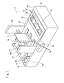
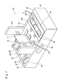
- a cut-sheet feeder 10 has various types of parts disposed on a base frame 90.
- the base frame 90 which is formed as a whole in the shape of a box, includes side plates 92 and 92 opposed to each other in the horizontal direction and an upper surface plate 93 for coupling between the rear end portions of the side plates 92. Note that the upper surface plate 93 is in parallel to the horizontal plane.
- a parts mounting unit 94 At the substantial center of the side plates 92 and 92 in the back-and-forth direction, side walls 94S and 94S stand upright. At a position sandwiched between those side walls 945 and 945, there is provided a parts mounting unit 94.
- a stock unit 70 Provided behind the parts mounting unit 94 is a stock unit 70 in which a stack of cut sheets G can be placed with a plurality of cut sheets S stacked on top of another in the up-and -down direction (see Fig. 2 ). Note that in the drawings to be herein referred to, the thickness of the cut sheet S and the gap between the cut sheets S in the stack of cut sheets G are exaggerated for the purpose of illustration.
- the stock unit 70 has a front end wall 71 in contact with the rear surface of the parts mounting unit 94.
- the front end wall 71 is substantially perpendicular to the upper surface plate 93 and has the lower end portion extending forward. Between the lower edge of the front end wall 71 and a belt feed part 60 to be discussed later, there is formed a cut-sheet ejection port 72 through which the cut sheet S can pass.
- the inclined guide member 73 is integrated with a plurality of triangular plates 74 aligned in the direction of the width of the base frame 90 (in the direction of the side plates 92 and 92 being opposed to each other) and a mounting plate 75 for fixing the triangular plates 74 to the upper surface plate 93 (see Fig. 1 ).
- the triangular plates 74 When viewed from a side, the triangular plates 74 have the shape of a right-angled triangle with a forwardly declining hypotenuse, so that the inclined surface is in contact with the rear end edge of a plurality of cut sheets S of those placed in the stock unit 70, the plurality of cut sheets S being located on the lower end side. This allows the lower cut sheets S of those stacked on top of another to be shifted forward relative to the upper cut sheets S.
- the inclined surface of the triangular plates 74 serves as a guide surface 73M of the present invention.
- the mounting plate 75 has a second elongated guide hole 75A which extends in the back-and-forth direction and penetrates therethrough.
- the upper surface plate 93 also has an elongated base hole 93A which extends in the back-and-forth direction and penetrates therethrough.
- the position of the inclined guide member 73 in the back-and-forth direction can be varied along the second elongated guide hole 75A and the elongated base hole 93A, and thus the position of the inclined guide member 73 can be selectively adjusted in the back-and-forth direction depending on the size of the cut sheet S.
- the belt feed part 60 which draws forwardly and slidingly feeds the plurality of cut sheets S placed in the stock unit 70 sequentially from the lower end side.
- feed belts 63 which are each stretched over a rear pulley 61 disposed immediately below the stock unit 70 and a front pulley 62 disposed at a forward position relative to the stock unit 70.
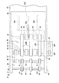
- the plurality of feed belts 63 which are identical to each other, are disposed to be in parallel to each other in the width direction of the base frame 90.
- a rear shaft 64 and a front shaft 65 are interposed which are parallel to each other and horizontally aligned.
- the rear shaft 64 and the front shaft 65 are pivotally supported at both ends thereof with bearings (not shown) in the side plates 92 and 92.
- the rear shaft 64 has the plurality of rear pulleys 61 pivotally supported so as to be spaced from each other, while the front shaft 65 has the same number of front pulleys 62 as that of the rear pulleys 61 pivotally supported so as to be spaced from each other.
- the respective feed belt 63 is stretched over the rear pulley 61 and the front pulley 62 which are aligned in the back-and-forth direction.
- the feedbelt 63 is adapted to be brought into frictional contact with the lower surface of the lowermost cut sheet S of the stack of cut sheets G placed in the stock unit 70, thereby drawing the lowermost cut sheet S through the cut-sheet ejection port 72 of the stock unit 70 so as to slidingly feed forward the cut sheet S.
- the feed belt 63 has an upwardly oriented surface which serves as a rotational contact surface 63M in contact with the cut sheet S, and the rotational contact surface 63M is disposed in parallel to the upper surface plate 93.
- the feed belt 63 is driven by a servomotor 66 disposed under the upper surface plate 93. That is, an output pulley 66P is fixed to the output shaft (not shown) coupled to a rotor of the servomotor 66, while a driving pulley 65P is fixed to one end portion of the front shaft 65 which penetrates one of the side plates 92. Moreover, a timing belt 67 is stretched over the output pulley 66P and the driving pulley 65P. Note that the tension of the timing belt 67 can be adjusted by a tension roller (not shown).
- a double-feed restrictor 30 At a position spaced apart forwardly from the cut-sheet ejection port 72 of the stock unit 70, there is provided a double-feed restrictor 30.
- the double-feed restrictor 30 is vertically movably supported by a support member 31 mounted to the front end portion of the parts mounting unit 94.
- the double-feed restrictor 30 is also biased downward by a compression coil spring (not shown).
- the cut sheet S drawn from the stock unit 70 by rotation of the feed belt 63 pushes up the double-feed restrictor 30 so as to pass through between the double-feed restrictor 30 and the feed belt 63.
- a downstream belt feed part 80 for allowing the cut sheet S discharged through the cut-sheet ejection port 72 to be fed further in the forward direction.
- the downstream feed belt part 80 is configured in the same manner as the belt feed part 60, so that a plurality of downstream feed belts 83 are each stretched over a downstream rear pulley 81 and a downstream front pulley 82.
- the downstream feedbelts 83 which are identical to each other, are disposed in parallel to each other in the width direction of the base frame 90 (see Fig. 2 ). Note that the downstream feed belt 83 is also provided with an upwardly oriented transport surface which is adapted to be flush with the upper surface of the upper surface plate 93.
- a downstream rear shaft 84 and a downstream front shaft 85 which are parallel to each other and horizontally aligned are pivotally supported.
- the plurality of downstream front pulleys 81 and the plurality of downstream rear pulleys 81 are pivotally supported on the downstream front shaft 85 and the downstream rear shaft 84, respectively, so as to be spaced from each other.
- the respective downstream feed belt 83 is stretched over the downstream rear pulley 81 and the downstream front pulley 82 aligned in the back-and-forth direction.
- the downstream rear shaft 84 is coupled to the front shaft 65 of the aforementionedbelt feedpart 60. Specifically, there is a coupling belt 87 stretched over a downstream coupling pulley 86 pivotally supported on the downstream rear shaft 84 and a coupling pulley 69 pivotally supported on the front shaft 65. This allows the downstream feed belt 83 to rotate by receiving a drive force form the servomotor 66.
- thecouplingpulley69andthedownstreamcoupling pulley 86 have the same diameter at one axial end side (the lower side in Fig. 2 ), so that when the coupling belt 87 is stretched over the coupling pulley 69 and the downstream coupling pulley 86 on the one end side, the feed speed of the downstream feed belt 83 becomes the same as the feed speed of the feed belt 63.
- the other axial end side of the coupling pulley 69 (the upper side in Fig. 2 ) is greater in diameter than the one end side and the other axial end side of the downstream coupling pulley 86 is less in diameter than the one end.
- the downstream feed belt 85 is configured to be brought into frictional contact with the lower surface of the cut sheet S discharged through the cut-sheet ejection port 72 of the stock unit 70, thereby further feeding the discharged cut sheet S in the forward direction.
- a plurality of press rollers 88 are rotatably and pivotally supported so as to press, from above, the cut sheet S being fed by the downstream feed belt 83.
- the cut-sheet feeder 10 of this embodiment is provided on the upper surface plate 93 with a belt contact amount adjuster 20 which is slidable in the back-and-forth direction.
- the belt contact amount adjuster 20 is horizontal plate-shaped and aligned in parallel to the rotational contact surface 63M of the feed belt 63.
- the belt contact amount adjuster 20 pushes up the rear portion of the lowermost cut sheet of the stack of cut sheets G off the feed belt 63, and supports the front portion of the lowermost cut sheet of the stack of cut sheets G rotationally contactably with the feed belt 63.
- the belt contact amount adjuster 20 has a first elongated guide hole 20A which extends in the back-and-forth direction and penetrates therethrough. Then, with the first elongated guide hole 20A and the elongated base hole 93A of the upper surface plate 93 overlapping each other, the nut N is fastened to the bolt B which penetrates through the first elongated guide hole 20A and the elongated base hole 93A, thereby fixing the belt contact amount adjuster 20 to the upper surface plate 93. By loosening the bolt B, the position of the belt contact amount adjuster 20 can be varied in the back-and-forth direction along the first elongated guide hole 20A and the elongated base hole 93A. Note that there is a slight gap formed between the belt contact amount adjuster 20 and the feed belt 63 so as to prevent the belt contact amount adjuster 20 from being brought into contact with the feed belt 63 (see Fig. 5C ).
- the belt contact amount adjuster 20 is sandwiched between the mounting plate 75 of the inclined guide member 73 and the upper surface plate 93.
- the belt contact amount adjuster 20 is fixed to the upper surface plate 93 by screwing the bolt B into the nut N so as to fix the mounting plate 75 and the upper surface plate 93 together, with the elongated base hole 93A of the upper surface plate 93, the first elongated guide hole 20A of the belt contact amount adjuster 20, and the second elongated guide hole 75A of the mounting plate 75 overlapping each other.
- the belt contact amount adjuster 20 is provided on the lower surface thereof with engaging projections 21 and 21 which extend in the back-and-forth direction (only one of the engagingprojections 21 is illustrated in Fig. 4 ).
- the engaging projections 21 and 21 are engaged with slits 93S and 93S which are formed rearwardly from the front end portion of the upper surface plate 93 (see Fig. 3 ) so as to restrict movement of the belt contact amount adjuster 20 in the width direction (in the vertical direction of Fig. 3 ).
- the first elongated guide hole 20A serves as the "first guide” of the present invention
- the second elongated guide hole 75A serves as the "second guide.”
- the bolt B and the nut N constitute the "first fixing part” and the "second fixing part” of the present invention.
- the second elongated guide hole 75A, the bolt B, and the nut N constitute an inclined guide member variable support mechanism 76 of the present invention
- the first elongated guide hole 20A, the bolt B, and the nut N constitute a belt contact amount adjusting mechanism 26 of the present invention.
- the back-and-forth positions of the belt contact amount adjuster 20 and the inclined guide member 73 are adjusted, and then cut sheets S to be fed are set by stacking on top of another in the stock unit 70.
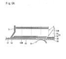
- Fig. 5A shows the case where the front end of the belt contact amount adjuster 20 is disposed near the rear end of the stack of cut sheets G.
- the rear end of the lower end portions of the stack of cut sheets G is supported on the inclined guide surface 73M of the inclined guide member 73 in a manner such that the cut sheets S located at the lower end portion of the stack of cut sheets G are shifted forward as moving downwardly.
- the section of the stack of cut sheets G more frontward than the section supported by the inclined guide member 73 is supported by the belt contact amount adjuster 20, while the section of the stack of cut sheets G more frontward than the section supported by the belt contact amount adjuster 20 is in contact with the feed belt 63.
- the belt contact amount adjuster 20 has a horizontal upper surface which enables stable supporting of the stack of cut sheets G.
- the feed belt 63 is rotationally driven and then the rotational contact surface 63M of the feed belt 63 is brought into frictional contact with the lower surface of a first cut sheet S1 located at the lowermost section of the stack of cut sheets G, so that the first cut sheet S1 moves forward from the stock unit 70 through the cut-sheet ejection port 72.
- the kinetic friction force received by the second cut sheet S2 from the feed belt 63 also becomes greater than the static friction force between the second cut sheet S2 and a third cut sheet S3 on top of the second cut sheet, allowing the second cut sheet S2 to start to be fed.
- the cut sheets S are sequentially fed forward from the lower end side of the stack of cut sheets G.
- the belt contact amount adjuster 20 disposed forward causes the contact between the rear end portion of the lower surface of the second cut sheet S2 and the feed belt 63 to be prevented by the belt contact amount adjuster 20 when the first cut sheet S1 moves forward due to the frictional contact with the feed belt 63.
- This will make the contact area between the second cut sheet S2 and the feed belt 63 less than that shown in Fig. 5B (see Fig. 5D ).
- it is made possible to reduce the kinetic friction force produced between the second cut sheet S2 and the feed belt 63, so that when the first cut sheet S1 has been completely drawn from the stack of cut sheets G, the second cut sheet S2 can start to be fed. That is, the partial double feeding of the cut sheet S can be resolved.
- the upper surface of the belt contact amount adjuster 20 is horizontal and has a smaller angle of inclination with respect to the horizontal plane than the guide surface 73M of the inclined guide member 73.
- this prevents the rear side of the stack of cut sheets G from being lifted up, so that the belt contact amount adjuster 20 can be adjusted with ease to such a position as to be capable of resolving the partial double feeding of the cut sheet S.
- the cut sheet S drawn from the stock unit 70 enters into between the double-feed restrictor 30 and the feed belt 63 and passes therethrough while pushing up the double-feed restrictor 30 so as to be further fed in the forward direction by the downstream feed belt 83.
- the feed speed of the downstream feed belt 83 can be made higher than the feed speed of the feed belt 63.
- the cut-sheet feeder 10 of this embodiment allows the plate variable support mechanism 26 to vary the position of the belt contact amount adjuster 20 in the direction of feeding of cut sheets so as to adjust the contact area between the feed belt 63 and the stack of cut sheets G.
- the partial double feeding can be prevented, or even if not, the overlap amount between the cut sheets S can be reduced to such an extent that the overlap between the cut sheets S can be resolved later in post processing. It is therefore possible to reduce the occurrence of partial double feeding when compared with before. It is also possible to allow the inclined guide member 73 to shift forward the cut sheet S located at the lower end portion of the stack of cut sheets G, thereby assisting in reducing the occurrence of partial double feeding.
- the inclined guide member 73 can vary its position in the direction of feeding of cut sheets by the inclined guide member variable support mechanism 76, changes in the size of the cut sheet S can be accommodated. Furthermore, since this embodiment allows the positions of the belt contact amount adjuster 20 and the inclined guide member 73 to be varied separately, the contact area between the cut sheet S and the feed belt 63 can be varied with the inclined guide member 73 kept fixed at a position depending on the size of the cut sheets S.
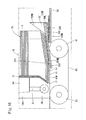
- a cut-sheet feeder 10V features that the configuration of a belt contact amount adjuster 20V is mainly different from the configuration of the belt contact amount adjuster 20 of the first embodiment.
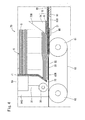
- the belt contact amount adjuster 20V has a cover section 24 with an upper surface parallel to a horizontal plane, and the cover section 24 covers the range of the rotational contact surface 63M of the feed belts 63 from the rear end to an intermediate position thereof. Note that, more specifically, the cover section 24 is horizontal plate-shaped and aligned so as to be sandwiched between an upper surface cover 93 and the mounting plate 75 of the inclined guide member 73.
- the cover section 24 has the first elongated guide hole 20A which is formed to penetrate therethrough in the same manner as with the belt contact amount adjuster 20 of the first embodiment. Then, with the first elongated guide hole 20A and the elongated base hole 93A of the upper surface plate 93 overlapping each other, the nut N is fastened to the bolt B having penetrated through the elongated holes 20A and 93A, thereby fixing the belt contact amount adjuster 20 to the upper surface plate 93. That is, the cut-sheet feeder 10V of this embodiment is configured to include the belt contact amount adjusting mechanism 26 of the first embodiment. Note that a slight gap is formed between the cover section 24 and the feed belts 63, so that the cover section 24 is not brought into contact with the feed belts 63.
- the engaging projections 21 and 21 which are the same as those of the first embodiment are provided (only one of the engaging projections is illustrated in Fig. 9 ).
- the engaging projections 21 and 21 are engaged with the slits 93S and 93S of the upper surface plate 93 (see Fig. 8 ) so as to restrict movement of the belt contact amount adjuster 20V in the width direction (in the vertical direction of Fig. 8 ).
- the belt contact amount adjuster 20V includes a plurality of hand-over projections 25 which are protruded from the front end of the cover section 24.
- the hand-over projections 25 and the feed belts 63 are disposed alternately side by side, and the front end portion of the hand-over projections 25 is disposedbelow the rotational contact surface 63M of the feed belts 63.
- the plurality of hand-over projections 25 and the plurality of feed belts 63 form a hand-over section 27 of the present invention.
- the hand-over projection 25 is constituted by an inclined section 25A which is inclined from the front end of the cover section 24 forwardly downward and a straight section 25B which forwardly extends from the front end of the inclined section 25A.
- the upper surface of the rear end portion of the inclined section 25A is located above the rotational contact surface 63M of the feed belt 63, while the upper surface of the front end portion of the inclined section 25A is located below the rotational contact surface 63M.
- a section of the upper surface of the hand-over projections 25 constitutes a hand-over inclined surface 25M of the present invention, the section being disposed above the rotational contact surface 63M of the feed belt 63, and the upper surface of the cover section 24 constitutes a cut-sheet main support surface 24M of the present invention.
- the upper surface of the inclined section 25A is curved so as to be oriented downwardly in the forward direction.
- the belt contact amount adjuster 20V has been completely described.
- Other components of the cut-sheet feeder 10V are configured in the same manner as those of the cut-sheet feeder 10 of the aforementioned first embodiment, and will be denoted with identical symbols without repeated explanations.
- the cut-sheet feeder 10V can provide the same effects as those of the cut-sheet feeder 10 of the first embodiment. Furthermore, the front end portion of a section of the hand-over projection 25, the section being located above the rotational contact surface 63M of the feed belt 63, that is, the hand-over inclined surface 25M is inclined forwardly downward. Thus, when the cut sheet S is drawn from the stack of cut sheets G, it is possible to smoothly hand over the rear portion of the cut sheet S supported by the belt contact amount adjuster 20V to the feedbelts 63. In addition, according to this embodiment, since the upper surface of the hand-over projection 25 and the rotational contact surface 63M intersect when viewed from the side, the cut sheet S can be prevented from being folded at the hand-over section.
- a cut-sheet feeder 10W of this embodiment features that the configuration of a belt contact amount adjuster 20W is mainly different from that of the belt contact amount adjuster 20V of the second embodiment. More specifically, the belt contact amount adjuster 20W has a flat surface, the upper surface of the entirety of which is inclined forwardly downward.
- the belt contact amount adjuster 20W includes a plurality of hand-over projections 25W disposed between adj acent feedbelts 63 and 63 and a cover section 24W in communication with the rear ends of the plurality of hand-over projections 25W.
- the cover section 24W is provided at the rear end portion with a plurality of slits 24WS so as to allow the triangular plates 74 of inclined guide members 73W to be movable in the back-and-forth direction in the slits 24WS.
- the upper surface of the cover section 24W serves as a main support surface 24WM for supporting a stack of cut sheets according to the present invention and is located below a guide surface 73WM of the inclined guide member 73W when viewed from the side (see Fig. 12 ).
- the hand-over projections 25W have the upper surface of the rear end portion which is located above the rotational contact surface 63M and the upper surface of the front end portion which is located below the rotational contact surface 63M.
- a section of the upper surface of the hand-over projection 25W, the section being located above the feed belt 63, serves as a hand-over inclined surface 25WM according to the present invention.
- the plurality of hand-over projections 25W and the plurality of feed belts 63 constitute a hand-over section 27W of the present invention.
- brackets 23 and 23 for fixing the belt contact amount adjuster 20W to the upper surface plate 93.
- the bracket 23 has the shape of a letter "L" when viewed in the back-and-forth direction, and a bottom plate 23T thereof, which is stacked on the mounting plate 75W of the inclined guide member 73W.
- the bottom plate 23T of the bracket 23 has a first elongated guide hole 20WA which is formed to extend in the back-and-forth direction. Furthermore, the mounting plate 75W of the inclined guide member 73W also has a second elongated guide hole 75WA which is formed to extend in the back-and-forth direction and penetrate therethrough.
- the bolt B penetrating through the first elongated guide hole 20WA and the second elongated guide hole 75WA is screwed into a spiral hole 93N formed in the upper surface plate 93, thereby allowing the belt contact amount adjuster 20W and inclined guide member 93W to be fixed to the upper surface plate 93.
- the second elongated guide hole 75WA serves as the "second guide” of the present invention
- the bolt B and the spiral hole 93N constitute the "second fixing part" of the present invention.
- the second elongated guide hole 75WA, the bolt B, and the spiral hole 93N constitute an inclined guide member variable support mechanism 76W of the present invention.
- the first elongated guide hole 20WA serves as the "first guide” of the present invention
- the bolt B and the spiral hole 93N constitute the "second fixingpart” of the present invention.
- the first elongated guide hole 20A, the bolt B, and the spiral hole 93N constitute the belt contact amount adjusting mechanism 26W of the present invention.
- the belt contact amount adjuster 20W has been completely described. Furthermore, other components of the cut-sheet feeder 10W are configured in the same manner as those of the cut-sheet feeder 10V of the aforementioned second embodiment, and will be denoted with identical symbols without repeated explanations.
- the cut-sheet feeder 10W according to this embodiment can provide the same effects as those of the second embodiment.
- a cut-sheet feeder 10X of this embodiment features that the configuration of a belt contact amount adjuster 20X is mainly different from that of the belt contact amount adjuster 20W of the third embodiment.
- the belt contact amount adjuster 20X includes a plurality of strip-shaped members 40 which are elongated in the back-and-forth direction and disposed side by side.
- the strip-shaped members 40 are coupled to each other by a coupling shaft 41 at an intermediate position in the back-and-forth direction.
- the feed belts 63 and the strip- shaped members 40 are disposed alternately.
- the cut-sheet feeder 10X has the inclined guide members 73W of the aforementioned third embodiment, so that the rear portions of the strip-shapedmembers 40 are disposedbetween the adj acent triangular plates 74 of the inclined guide member 73W.
- the inclined guide member 73W can be fixed at a given position in the back-and-forth direction by means of the inclined guide member variable support mechanism 76W as described in the third embodiment.
- the strip-shaped member 40 has a flat surface, the entire upper surface of which is inclined forwardly downward.
- the rear end of the upper surface of the strip-shaped member 40 is disposed above the rotational contact surface 63M of the feed belt 63, whereas the front end thereof is disposed below the rotational contact surface.
- the strip-shaped member 40 is configured such that the rear portion is formed of a trapezoidal block and the front portion is formed as a plate-shaped hand-over projection 25X which is inclined forwardly downward.
- a section of the upper surface of the hand-over projection 25X constitutes a hand-over inclined surface 25XM of the present invention
- a section of the upper surface of the strip-shaped member 40, the section being more rearward than the hand-over inclined surface 25XM constitutes a cut-sheet main support surface 24XM.
- a plurality of hand-over projections 25X and a plurality of feed belts 63 form the hand-over section 27X of the present invention.
- the outer strip-shaped members 40 and 40 in the width direction of the feed belts 63 include brackets 42 and 42 for fixing the strip-shaped members 40 to the upper surface plate 93.
- the bracket 42 is configured in the same manner as the bracket 23 of the aforementioned third embodiment, so that the belt contact amount adjuster 20X includes the belt contact amount adjusting mechanism 26W described in the third embodiment.
- the belt contact amount adjuster 20X has been completely described.
- Other components of the cut-sheet feeder 10X are configured in the same manner as those of the cut-sheet feeder 10W of the third embodiment, and will be denoted with identical symbols without repeated explanations.
- the cut-sheet feeder 10X according to this embodiment can provide the same effects as those of the aforementioned second and the third embodiments.
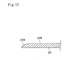
- a belt contact amount adjuster 20Y of this embodiment is a horizontal plate with a deformed front end portion, and the upper surface of the front end portion has a hand-over inclined surface 25YM which is inclined forwardly downward. Furthermore, a section of the upper surface of the belt contact amount adjuster 20Y, the sectionbeingmore rearward than the hand-over inclined surface 25YM, serves as a cut-sheet main support surface 24YM. Note that, more specifically, the hand-over inclined surface 25YM is curved in an elliptical shape so as to be oriented downwardly in the forward direction when viewed from the side.
- This embodiment can provide the same effects as those of the aforementioned first embodiment. Furthermore, the hand-over inclined surface 25YM is inclined forwardly downward. Thus, when the cut sheet S is drawn from the stack of cut sheets G, it becomes possible to smoothly hand over the rear portion of the cut sheet S supported by the belt contact amount adjuster 20Y to the feed belts 63.
- the cut-sheet main support surface 24M is horizontal; however, the surface 24Mmay also be inclined forwardly downward relative to a horizontal plane at a smaller angle than that of the hand-over inclined surface 25M with respect to the plane.
- a plurality of feed belts and hand-over projections are included and disposed alternately; however, it is also acceptable that a pair of feed belts is included and a hand-over projection is disposed between the pair of feed belts, or alternatively a pair of hand-over projections is included and a feed belt is disposed between the pair of hand-over projections.
- a plate-shaped member which is inclined forwardly downward may also be employed.
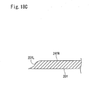
- the shape of the hand-over inclined surface 25YM of the aforementioned fifth embodiment is not limited to that shown in Fig. 17 ; for example, it may also be like a hand-over inclined surface 25YJ, 25YK, or 25YL shown in Fig. 18A to Fig. 18C .
- the feed belt 63 and the downstream feed belt 83 are driven by the same driving source; however, each may also be driven by a separate driving source.
- the upper surface plate 93 and the rotational contact surface 63M of the feed belt 63 are horizontally disposed; however, they may also be inclined so as to be forwardly lowered relative to a horizontal plane. Furthermore, at that time, the cut-sheet main support surface may be disposed in parallel to the rotational contact surface 63M.
- the belt contact amount adjusting mechanism 26 and the inclined guide member variable support mechanism 76 which are described in the aforementioned first embodiment may each be exchanged with the belt contact amount adjusting mechanism 26W and the inclined guide member variable support mechanism 76W which are described in the aforementioned second embodiment.
- the rank and pinion mechanism may be employed to constitute the "belt contact amount adjusting mechanism" of the present invention. More specifically, as shown in Fig. 19 , the belt contact amount adjuster 20 may be provided with a rack 120A which extends in the back-and-forth direction (equivalent to the "first guide” of the present invention), while a pinion 120B mating with the rack 120A (equivalent to the "first fixing part” of the present invention) maybeprovided on the upper surface plate 93.
- a ball screw mechanism may be employed to constitute the "belt contact amount adjusting mechanism" of the present invention. More specifically, as shown in Fig.
- the belt contact amount adjuster 20 may be provided with a ball screw 121A which extends in the back-and-forth direction (equivalent to the "first guide” of the present invention), and with a ball nut 121B which is screwed over the ball screw 121A (equivalent to the "first fixing part” of the present invention).
- a ball screw 121A which extends in the back-and-forth direction (equivalent to the "first guide” of the present invention)
- a ball nut 121B which is screwed over the ball screw 121A (equivalent to the "first fixing part” of the present invention).
- the rack and pinion mechanism and the ball screw mechanism may be applied to the inclined guide member variable support mechanism.
- the lower surface of the belt contact amount adjuster 20 and the upper surface plate 93 as well as the upper surface of the belt contact amount adjuster 20 and the inclined guide member 73 may be adapted to be coupled to each other by a magnet so that the belt contact amount adjuster 20 and the inclined guide member 73 can be fixed at a given position in the back-and-forth direction.
- first guide rail 122A which extends in the back-and-forth direction (equivalent to the "first guide” of the present invention) and a first slider 122B which moves integrally with the belt contact amount adjuster 20 and can be fixed at a given position along the first guide rail 122A.
- the first slider includes a first locking pawl 122C which can reciprocate between a locking position at which the first locking pawl 122C is locked in a first locking section 122E formed in the first guide rail 122A and a first release position at which the locking is released.
- the first slider also includes a first spring 122D for energizing the first locking pawl 122C to the first locking position. Furthermore, in order to constitute the "inclined guide member variable support mechanism" of the present invention, it is also acceptable to employ a second guide rail 123B (equivalent to the "second guide” of the present invention) which is formed on the upper surface of the upper surface plate 93 and extends in the back-and-forth direction, and a second slider 123B (equivalent to the "second fixing part” of the present invention) which moves integrally with the inclined guide member 73 and can be fixed at a given position along the second guide rail 123A. Note that the second guide rail 123A and the second slider 123B are configured in the same manner as the first guide rail 122A and the first slider 122B.
- the "belt contact amount adjustingmechanism" of the present invention maybe constituted by first positioning holes 125A formed on the upper surface of the upper surface plate 93 and aligned in the back-and-forth direction and first positioning pins 125B penetrating through the belt contact amount adjuster 20 and engaging with the first positioning holes 125A.
- the "inclined guide member variable support mechanism” of the present invention may be constituted by second positioning holes 126A formed on the upper surface of the upper surface plate 93 and aligned in the back-and-forth direction, and second positioning pins 12 6B which penetrate through a bracket 127 moving integrally with the inclined guide member 73 and engage with the second positioning hole 126A.
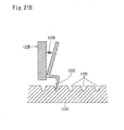
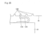
- the belt contact amount adjuster 20 may be provided with an elastic member 128C (equivalent to the "first spring" of the present invention) with the tip end being outwardly energized. Furthermore, the elastic member 128C may be provided at the tip end with a first locking pawl 128A formed to be protruded outwardly, and a plurality of first locking sections 128B which can engage with the first locking pawl 128A are provided in the upper surface plate 93 so as to be aligned in the back-and-forth direction, thereby constituting the belt contact amount adjusting mechanism. Note that the configuration of the belt contact amount adjusting mechanism may be applied to the guide variable support mechanism.
- a clamp as the "belt contact amount adjusting mechanism" and the "inclined guide member variable support mechanism” of the present invention. That is, as shown in Fig. 24 , the belt contact amount adjuster 20, the mounting plate 75 of the inclined guide member 73, and the upper surface plate 93 may be clamped with a clamp 130, thereby allowing the clamp 130 to fix the belt contact amount adjuster 20 and the inclined guide member 73 at a given position in the back-and-forth direction.
Landscapes
- Engineering & Computer Science (AREA)
- Mechanical Engineering (AREA)
- Sheets, Magazines, And Separation Thereof (AREA)
- Basic Packing Technique (AREA)
Applications Claiming Priority (2)
| Application Number | Priority Date | Filing Date | Title |
|---|---|---|---|
| JP2011018161A JP4886075B1 (ja) | 2011-01-31 | 2011-01-31 | カット紙送給装置 |
| PCT/JP2012/052035 WO2012105519A1 (ja) | 2011-01-31 | 2012-01-30 | カット紙送給装置 |
Publications (3)
| Publication Number | Publication Date |
|---|---|
| EP2644541A1 true EP2644541A1 (de) | 2013-10-02 |
| EP2644541A4 EP2644541A4 (de) | 2014-04-02 |
| EP2644541B1 EP2644541B1 (de) | 2015-01-28 |
Family
ID=45851285
Family Applications (1)
| Application Number | Title | Priority Date | Filing Date |
|---|---|---|---|
| EP12742565.0A Not-in-force EP2644541B1 (de) | 2011-01-31 | 2012-01-30 | Vorrichtung zum zuführen geschnittener papierbögen |
Country Status (7)
| Country | Link |
|---|---|
| US (1) | US8678373B2 (de) |
| EP (1) | EP2644541B1 (de) |
| JP (1) | JP4886075B1 (de) |
| KR (1) | KR101853479B1 (de) |
| CN (1) | CN103347803B (de) |
| AU (1) | AU2012211807B2 (de) |
| WO (1) | WO2012105519A1 (de) |
Families Citing this family (24)
| Publication number | Priority date | Publication date | Assignee | Title |
|---|---|---|---|---|
| JP4886075B1 (ja) | 2011-01-31 | 2012-02-29 | 江沢事務器株式会社 | カット紙送給装置 |
| JP5377677B2 (ja) * | 2012-01-30 | 2013-12-25 | 江沢事務器株式会社 | カット紙送給装置 |
| JP2014122095A (ja) * | 2012-12-21 | 2014-07-03 | Hitachi Omron Terminal Solutions Corp | 紙幣取扱装置 |
| JP2015030562A (ja) * | 2013-07-31 | 2015-02-16 | 江沢事務器株式会社 | カット紙供給機 |
| CN103693467A (zh) * | 2013-12-03 | 2014-04-02 | 无锡佳泰科技有限公司 | 一种标签纸分发装置的上料调节机构 |
| CN103693258A (zh) * | 2013-12-03 | 2014-04-02 | 无锡佳泰科技有限公司 | 一种标签纸分发装置 |
| CN103693465B (zh) * | 2013-12-04 | 2018-01-12 | 无锡佳泰科技有限公司 | 一种标签纸分发装置的改进结构 |
| JP6204824B2 (ja) * | 2013-12-26 | 2017-09-27 | 株式会社Isowa | 段ボールシートの給紙装置 |
| CN103935784B (zh) * | 2014-04-29 | 2016-08-24 | 上海美声服饰辅料有限公司 | 标签纸输送机构 |
| TWI577569B (zh) * | 2015-08-11 | 2017-04-11 | 虹光精密工業股份有限公司 | 傳動組件及包括其之事務機 |
| CN105293117A (zh) * | 2015-11-09 | 2016-02-03 | 宁波平海机械设备有限公司 | 自动送料机构及其送料方法 |
| CN105540244B (zh) * | 2016-01-28 | 2017-12-12 | 江苏新美星包装机械股份有限公司 | 纸箱裹包机中的进纸装置 |
| CN105936348A (zh) * | 2016-06-15 | 2016-09-14 | 成都精机自动化技术有限公司 | 一种新型自动上料设备 |
| CN106742252A (zh) * | 2017-01-11 | 2017-05-31 | 珠海格力智能装备技术研究院有限公司 | 进料机构及具有其的装袋机 |
| CN106742250A (zh) * | 2017-01-11 | 2017-05-31 | 珠海格力智能装备技术研究院有限公司 | 进料机构及具有其的装袋机 |
| CN106742256A (zh) * | 2017-01-11 | 2017-05-31 | 珠海格力智能装备技术研究院有限公司 | 进料机构及具有其的装袋机 |
| CN106742249A (zh) * | 2017-01-11 | 2017-05-31 | 珠海格力智能装备技术研究院有限公司 | 进料机构及具有其的装袋机 |
| CN106742255A (zh) * | 2017-01-11 | 2017-05-31 | 珠海格力智能装备技术研究院有限公司 | 进料机构及具有其的装袋机 |
| CN106742254A (zh) * | 2017-01-11 | 2017-05-31 | 珠海格力智能装备技术研究院有限公司 | 进料机构及具有其的装袋机 |
| CN106697393A (zh) * | 2017-01-11 | 2017-05-24 | 珠海格力智能装备技术研究院有限公司 | 进料机构及具有其的装袋机 |
| CN106742253A (zh) * | 2017-01-11 | 2017-05-31 | 珠海格力智能装备技术研究院有限公司 | 进料机构及具有其的装袋机 |
| US11999583B2 (en) | 2019-10-08 | 2024-06-04 | Horizon International Inc. | Sheet conveyance apparatus |
| CN114834166B (zh) * | 2022-04-24 | 2023-11-21 | 厦门汉印电子技术有限公司 | 一种卡片输送设备及证卡打印机 |
| EP4685088A1 (de) | 2024-07-24 | 2026-01-28 | Print Group Spólka z Ograniczona Odpowiedzialnoscia | Entstapel- und ausgabevorrichtung für bücher und vorgeleimte buchblöcke |
Family Cites Families (23)
| Publication number | Priority date | Publication date | Assignee | Title |
|---|---|---|---|---|
| FR2011540A1 (de) * | 1968-06-24 | 1970-03-06 | Bobst Fils Sa J | |
| US3933350A (en) * | 1974-12-09 | 1976-01-20 | Mignano Frank J | Paper insert feeder |
| JPS5623133A (en) * | 1979-07-27 | 1981-03-04 | Fuji Xerox Co Ltd | Paper feeder |
| US4557472A (en) * | 1982-09-30 | 1985-12-10 | Stepper, Inc. | Multi-purpose feeder for successively delivering single sheet or multi-leaved articles from a stack thereof |
| US4715593A (en) * | 1985-12-02 | 1987-12-29 | Godlewski Edward S | Stack-supporting bottom feed conveyor |
| JPH0610057B2 (ja) * | 1987-10-23 | 1994-02-09 | ローレルバンクマシン株式会社 | 紙幣繰出装置 |
| US4991831A (en) | 1989-08-14 | 1991-02-12 | Green Ronald J | Paper sheet feeding apparatus |
| US5143365A (en) | 1989-08-14 | 1992-09-01 | Green Ronald J | Paper sheet feeding apparatus |
| US5244198A (en) * | 1992-04-28 | 1993-09-14 | Green Ronald J | Gate forming member for sheet feeding apparatus |
| JPH08217283A (ja) * | 1995-02-08 | 1996-08-27 | Konohana:Kk | 冊子類の分離搬送装置 |
| US5601282A (en) * | 1995-09-18 | 1997-02-11 | Milo; Alfred | Shingle feeder |
| US5642877A (en) * | 1996-02-23 | 1997-07-01 | Green; Ronald J. | Paper sheet feeding apparatus and gate forming member therefor |
| US5772199A (en) * | 1996-04-18 | 1998-06-30 | Streamfeeder, Llc | Envelope feeding apparatus |
| JPH10250257A (ja) * | 1997-03-12 | 1998-09-22 | Konohana:Kk | 冊子類の背貼り装置 |
| JPH10329953A (ja) * | 1997-06-03 | 1998-12-15 | Alps Electric Co Ltd | プリンタの給紙装置 |
| JPH1111694A (ja) * | 1997-06-23 | 1999-01-19 | Dainippon Printing Co Ltd | 刷本供給装置 |
| JP4553532B2 (ja) * | 2001-09-11 | 2010-09-29 | 共同印刷株式会社 | シート送出装置 |
| JP2005298078A (ja) * | 2004-04-06 | 2005-10-27 | Sanwa Seisaku Kk | 紙葉給送方法及び装置 |
| US7748696B2 (en) * | 2005-03-16 | 2010-07-06 | Kaiping James C | Sheet feeder with feed belts and traction belt |
| US7624978B2 (en) * | 2005-03-16 | 2009-12-01 | Kaiping James C | Sheet feeder with feed belts that move toward an away from each other |
| JP2010168201A (ja) | 2009-01-26 | 2010-08-05 | Sanray International Kk | ワーク給送装置 |
| AU2010222187B2 (en) * | 2009-03-09 | 2014-05-22 | Ezawa Jimuki Co., Ltd. | Device for feeding sheets, brochures, or the like, and system for sorting documents to be dispatched |
| JP4886075B1 (ja) | 2011-01-31 | 2012-02-29 | 江沢事務器株式会社 | カット紙送給装置 |
-
2011
- 2011-01-31 JP JP2011018161A patent/JP4886075B1/ja active Active
-
2012
- 2012-01-30 AU AU2012211807A patent/AU2012211807B2/en not_active Ceased
- 2012-01-30 WO PCT/JP2012/052035 patent/WO2012105519A1/ja not_active Ceased
- 2012-01-30 US US13/995,725 patent/US8678373B2/en not_active Expired - Fee Related
- 2012-01-30 KR KR1020137017806A patent/KR101853479B1/ko not_active Expired - Fee Related
- 2012-01-30 EP EP12742565.0A patent/EP2644541B1/de not_active Not-in-force
- 2012-01-30 CN CN201280006880.2A patent/CN103347803B/zh not_active Expired - Fee Related
Also Published As
| Publication number | Publication date |
|---|---|
| AU2012211807B2 (en) | 2016-04-14 |
| KR101853479B1 (ko) | 2018-05-02 |
| CN103347803B (zh) | 2015-11-25 |
| WO2012105519A1 (ja) | 2012-08-09 |
| CN103347803A (zh) | 2013-10-09 |
| AU2012211807A1 (en) | 2013-08-01 |
| KR20140030118A (ko) | 2014-03-11 |
| US8678373B2 (en) | 2014-03-25 |
| EP2644541A4 (de) | 2014-04-02 |
| EP2644541B1 (de) | 2015-01-28 |
| JP2012158420A (ja) | 2012-08-23 |
| US20130292895A1 (en) | 2013-11-07 |
| JP4886075B1 (ja) | 2012-02-29 |
Similar Documents
| Publication | Publication Date | Title |
|---|---|---|
| EP2644541B1 (de) | Vorrichtung zum zuführen geschnittener papierbögen | |
| US7850163B2 (en) | Sheet feeder with laterally adjustable sheet separators set below feed belt | |
| US8342510B2 (en) | Apparatus for feeding sheets, booklets or the like and system for sorting forwarding documents | |
| JP4249720B2 (ja) | 板状ワークピースを加工する機械において板状ワークピースを整列させるための装置 | |
| US10800631B2 (en) | Sheet stacking apparatus and image forming system | |
| JP5377677B2 (ja) | カット紙送給装置 | |
| CA2545402C (en) | Detachable feed tray with self adjusting side guides | |
| US7748696B2 (en) | Sheet feeder with feed belts and traction belt | |
| US20150119223A1 (en) | Sheet folding apparatus and sheet post-processing apparatus | |
| RU2011146062A (ru) | Устройство для подачи одного или нескольких ценных документов | |
| US20100201062A1 (en) | Side guide assembly with vertically repositionable side guides for use with friction sheet feeding machines | |
| JP7115018B2 (ja) | シート位置合わせ装置、シート搬送装置、シート読取装置及び画像形成装置 | |
| KR200450429Y1 (ko) | 트윈스프링 체결구 | |
| JPH11100132A (ja) | 自動給紙装置 | |
| JPH0912169A (ja) | シート送り装置 | |
| JP3885517B2 (ja) | 給紙装置 | |
| JP2016037373A (ja) | 給紙装置 | |
| US20100308529A1 (en) | Apparatuses for feeding sheets and printing apparatuses | |
| WO2006102035A2 (en) | Sheet feeder | |
| GB2480310A (en) | Friction belt sheet feeder with adjustable nip and dancing roller | |
| JPS6357446A (ja) | 給紙装置 | |
| JP2013010612A (ja) | 後処理装置及び画像形成装置 | |
| JP2008110824A (ja) | 給紙装置 | |
| JP2015030576A (ja) | 用紙後処理装置 | |
| JP2007137552A (ja) | カール矯正装置及び用紙後処理装置 |
Legal Events
| Date | Code | Title | Description |
|---|---|---|---|
| PUAI | Public reference made under article 153(3) epc to a published international application that has entered the european phase |
Free format text: ORIGINAL CODE: 0009012 |
|
| 17P | Request for examination filed |
Effective date: 20130627 |
|
| AK | Designated contracting states |
Kind code of ref document: A1 Designated state(s): AL AT BE BG CH CY CZ DE DK EE ES FI FR GB GR HR HU IE IS IT LI LT LU LV MC MK MT NL NO PL PT RO RS SE SI SK SM TR |
|
| A4 | Supplementary search report drawn up and despatched |
Effective date: 20140303 |
|
| RIC1 | Information provided on ipc code assigned before grant |
Ipc: B65H 1/06 20060101AFI20140225BHEP Ipc: B65H 3/54 20060101ALI20140225BHEP Ipc: B65H 3/68 20060101ALI20140225BHEP Ipc: B65H 3/04 20060101ALI20140225BHEP |
|
| DAX | Request for extension of the european patent (deleted) | ||
| GRAP | Despatch of communication of intention to grant a patent |
Free format text: ORIGINAL CODE: EPIDOSNIGR1 |
|
| RIC1 | Information provided on ipc code assigned before grant |
Ipc: B65H 3/04 20060101ALI20140924BHEP Ipc: B65H 1/06 20060101AFI20140924BHEP Ipc: B65H 9/10 20060101ALI20140924BHEP Ipc: B65H 3/54 20060101ALI20140924BHEP Ipc: B65H 3/68 20060101ALI20140924BHEP |
|
| INTG | Intention to grant announced |
Effective date: 20141010 |
|
| GRAS | Grant fee paid |
Free format text: ORIGINAL CODE: EPIDOSNIGR3 |
|
| GRAA | (expected) grant |
Free format text: ORIGINAL CODE: 0009210 |
|
| AK | Designated contracting states |
Kind code of ref document: B1 Designated state(s): AL AT BE BG CH CY CZ DE DK EE ES FI FR GB GR HR HU IE IS IT LI LT LU LV MC MK MT NL NO PL PT RO RS SE SI SK SM TR |
|
| REG | Reference to a national code |
Ref country code: GB Ref legal event code: FG4D |
|
| REG | Reference to a national code |
Ref country code: CH Ref legal event code: EP |
|
| REG | Reference to a national code |
Ref country code: IE Ref legal event code: FG4D |
|
| REG | Reference to a national code |
Ref country code: NL Ref legal event code: T3 |
|
| REG | Reference to a national code |
Ref country code: DE Ref legal event code: R096 Ref document number: 602012005186 Country of ref document: DE Effective date: 20150312 |
|
| REG | Reference to a national code |
Ref country code: AT Ref legal event code: REF Ref document number: 708135 Country of ref document: AT Kind code of ref document: T Effective date: 20150315 |
|
| REG | Reference to a national code |
Ref country code: AT Ref legal event code: MK05 Ref document number: 708135 Country of ref document: AT Kind code of ref document: T Effective date: 20150128 |
|
| REG | Reference to a national code |
Ref country code: LT Ref legal event code: MG4D |
|
| PG25 | Lapsed in a contracting state [announced via postgrant information from national office to epo] |
Ref country code: BE Free format text: LAPSE BECAUSE OF NON-PAYMENT OF DUE FEES Effective date: 20150131 |
|
| PG25 | Lapsed in a contracting state [announced via postgrant information from national office to epo] |
Ref country code: SE Free format text: LAPSE BECAUSE OF FAILURE TO SUBMIT A TRANSLATION OF THE DESCRIPTION OR TO PAY THE FEE WITHIN THE PRESCRIBED TIME-LIMIT Effective date: 20150128 Ref country code: ES Free format text: LAPSE BECAUSE OF FAILURE TO SUBMIT A TRANSLATION OF THE DESCRIPTION OR TO PAY THE FEE WITHIN THE PRESCRIBED TIME-LIMIT Effective date: 20150128 Ref country code: BG Free format text: LAPSE BECAUSE OF FAILURE TO SUBMIT A TRANSLATION OF THE DESCRIPTION OR TO PAY THE FEE WITHIN THE PRESCRIBED TIME-LIMIT Effective date: 20150428 Ref country code: HR Free format text: LAPSE BECAUSE OF FAILURE TO SUBMIT A TRANSLATION OF THE DESCRIPTION OR TO PAY THE FEE WITHIN THE PRESCRIBED TIME-LIMIT Effective date: 20150128 Ref country code: FI Free format text: LAPSE BECAUSE OF FAILURE TO SUBMIT A TRANSLATION OF THE DESCRIPTION OR TO PAY THE FEE WITHIN THE PRESCRIBED TIME-LIMIT Effective date: 20150128 Ref country code: LT Free format text: LAPSE BECAUSE OF FAILURE TO SUBMIT A TRANSLATION OF THE DESCRIPTION OR TO PAY THE FEE WITHIN THE PRESCRIBED TIME-LIMIT Effective date: 20150128 Ref country code: NO Free format text: LAPSE BECAUSE OF FAILURE TO SUBMIT A TRANSLATION OF THE DESCRIPTION OR TO PAY THE FEE WITHIN THE PRESCRIBED TIME-LIMIT Effective date: 20150428 |
|
| REG | Reference to a national code |
Ref country code: CH Ref legal event code: PL |
|
| PG25 | Lapsed in a contracting state [announced via postgrant information from national office to epo] |
Ref country code: IS Free format text: LAPSE BECAUSE OF FAILURE TO SUBMIT A TRANSLATION OF THE DESCRIPTION OR TO PAY THE FEE WITHIN THE PRESCRIBED TIME-LIMIT Effective date: 20150528 Ref country code: LV Free format text: LAPSE BECAUSE OF FAILURE TO SUBMIT A TRANSLATION OF THE DESCRIPTION OR TO PAY THE FEE WITHIN THE PRESCRIBED TIME-LIMIT Effective date: 20150128 Ref country code: GR Free format text: LAPSE BECAUSE OF FAILURE TO SUBMIT A TRANSLATION OF THE DESCRIPTION OR TO PAY THE FEE WITHIN THE PRESCRIBED TIME-LIMIT Effective date: 20150429 Ref country code: AT Free format text: LAPSE BECAUSE OF FAILURE TO SUBMIT A TRANSLATION OF THE DESCRIPTION OR TO PAY THE FEE WITHIN THE PRESCRIBED TIME-LIMIT Effective date: 20150128 Ref country code: PL Free format text: LAPSE BECAUSE OF FAILURE TO SUBMIT A TRANSLATION OF THE DESCRIPTION OR TO PAY THE FEE WITHIN THE PRESCRIBED TIME-LIMIT Effective date: 20150128 Ref country code: RS Free format text: LAPSE BECAUSE OF FAILURE TO SUBMIT A TRANSLATION OF THE DESCRIPTION OR TO PAY THE FEE WITHIN THE PRESCRIBED TIME-LIMIT Effective date: 20150128 |
|
| REG | Reference to a national code |
Ref country code: DE Ref legal event code: R097 Ref document number: 602012005186 Country of ref document: DE |
|
| PG25 | Lapsed in a contracting state [announced via postgrant information from national office to epo] |
Ref country code: CZ Free format text: LAPSE BECAUSE OF FAILURE TO SUBMIT A TRANSLATION OF THE DESCRIPTION OR TO PAY THE FEE WITHIN THE PRESCRIBED TIME-LIMIT Effective date: 20150128 Ref country code: MC Free format text: LAPSE BECAUSE OF FAILURE TO SUBMIT A TRANSLATION OF THE DESCRIPTION OR TO PAY THE FEE WITHIN THE PRESCRIBED TIME-LIMIT Effective date: 20150128 Ref country code: SK Free format text: LAPSE BECAUSE OF FAILURE TO SUBMIT A TRANSLATION OF THE DESCRIPTION OR TO PAY THE FEE WITHIN THE PRESCRIBED TIME-LIMIT Effective date: 20150128 Ref country code: EE Free format text: LAPSE BECAUSE OF FAILURE TO SUBMIT A TRANSLATION OF THE DESCRIPTION OR TO PAY THE FEE WITHIN THE PRESCRIBED TIME-LIMIT Effective date: 20150128 Ref country code: CH Free format text: LAPSE BECAUSE OF NON-PAYMENT OF DUE FEES Effective date: 20150131 Ref country code: DK Free format text: LAPSE BECAUSE OF FAILURE TO SUBMIT A TRANSLATION OF THE DESCRIPTION OR TO PAY THE FEE WITHIN THE PRESCRIBED TIME-LIMIT Effective date: 20150128 Ref country code: LI Free format text: LAPSE BECAUSE OF NON-PAYMENT OF DUE FEES Effective date: 20150131 Ref country code: RO Free format text: LAPSE BECAUSE OF FAILURE TO SUBMIT A TRANSLATION OF THE DESCRIPTION OR TO PAY THE FEE WITHIN THE PRESCRIBED TIME-LIMIT Effective date: 20150128 |
|
| REG | Reference to a national code |
Ref country code: IE Ref legal event code: MM4A |
|
| PLBE | No opposition filed within time limit |
Free format text: ORIGINAL CODE: 0009261 |
|
| STAA | Information on the status of an ep patent application or granted ep patent |
Free format text: STATUS: NO OPPOSITION FILED WITHIN TIME LIMIT |
|
| 26N | No opposition filed |
Effective date: 20151029 |
|
| REG | Reference to a national code |
Ref country code: FR Ref legal event code: PLFP Year of fee payment: 5 |
|
| PG25 | Lapsed in a contracting state [announced via postgrant information from national office to epo] |
Ref country code: IE Free format text: LAPSE BECAUSE OF NON-PAYMENT OF DUE FEES Effective date: 20150130 |
|
| PG25 | Lapsed in a contracting state [announced via postgrant information from national office to epo] |
Ref country code: SI Free format text: LAPSE BECAUSE OF FAILURE TO SUBMIT A TRANSLATION OF THE DESCRIPTION OR TO PAY THE FEE WITHIN THE PRESCRIBED TIME-LIMIT Effective date: 20150128 |
|
| PG25 | Lapsed in a contracting state [announced via postgrant information from national office to epo] |
Ref country code: BE Free format text: LAPSE BECAUSE OF FAILURE TO SUBMIT A TRANSLATION OF THE DESCRIPTION OR TO PAY THE FEE WITHIN THE PRESCRIBED TIME-LIMIT Effective date: 20150128 |
|
| PG25 | Lapsed in a contracting state [announced via postgrant information from national office to epo] |
Ref country code: MT Free format text: LAPSE BECAUSE OF FAILURE TO SUBMIT A TRANSLATION OF THE DESCRIPTION OR TO PAY THE FEE WITHIN THE PRESCRIBED TIME-LIMIT Effective date: 20150128 |
|
| REG | Reference to a national code |
Ref country code: FR Ref legal event code: PLFP Year of fee payment: 6 |
|
| PG25 | Lapsed in a contracting state [announced via postgrant information from national office to epo] |
Ref country code: SM Free format text: LAPSE BECAUSE OF FAILURE TO SUBMIT A TRANSLATION OF THE DESCRIPTION OR TO PAY THE FEE WITHIN THE PRESCRIBED TIME-LIMIT Effective date: 20150128 Ref country code: HU Free format text: LAPSE BECAUSE OF FAILURE TO SUBMIT A TRANSLATION OF THE DESCRIPTION OR TO PAY THE FEE WITHIN THE PRESCRIBED TIME-LIMIT; INVALID AB INITIO Effective date: 20120130 |
|
| PG25 | Lapsed in a contracting state [announced via postgrant information from national office to epo] |
Ref country code: CY Free format text: LAPSE BECAUSE OF FAILURE TO SUBMIT A TRANSLATION OF THE DESCRIPTION OR TO PAY THE FEE WITHIN THE PRESCRIBED TIME-LIMIT Effective date: 20150128 |
|
| PG25 | Lapsed in a contracting state [announced via postgrant information from national office to epo] |
Ref country code: PT Free format text: LAPSE BECAUSE OF FAILURE TO SUBMIT A TRANSLATION OF THE DESCRIPTION OR TO PAY THE FEE WITHIN THE PRESCRIBED TIME-LIMIT Effective date: 20150528 |
|
| PG25 | Lapsed in a contracting state [announced via postgrant information from national office to epo] |
Ref country code: TR Free format text: LAPSE BECAUSE OF FAILURE TO SUBMIT A TRANSLATION OF THE DESCRIPTION OR TO PAY THE FEE WITHIN THE PRESCRIBED TIME-LIMIT Effective date: 20150128 |
|
| PG25 | Lapsed in a contracting state [announced via postgrant information from national office to epo] |
Ref country code: LU Free format text: LAPSE BECAUSE OF NON-PAYMENT OF DUE FEES Effective date: 20150130 |
|
| REG | Reference to a national code |
Ref country code: FR Ref legal event code: PLFP Year of fee payment: 7 |
|
| PG25 | Lapsed in a contracting state [announced via postgrant information from national office to epo] |
Ref country code: MK Free format text: LAPSE BECAUSE OF FAILURE TO SUBMIT A TRANSLATION OF THE DESCRIPTION OR TO PAY THE FEE WITHIN THE PRESCRIBED TIME-LIMIT Effective date: 20150128 |
|
| PG25 | Lapsed in a contracting state [announced via postgrant information from national office to epo] |
Ref country code: AL Free format text: LAPSE BECAUSE OF FAILURE TO SUBMIT A TRANSLATION OF THE DESCRIPTION OR TO PAY THE FEE WITHIN THE PRESCRIBED TIME-LIMIT Effective date: 20150128 |
|
| PGFP | Annual fee paid to national office [announced via postgrant information from national office to epo] |
Ref country code: DE Payment date: 20190122 Year of fee payment: 8 Ref country code: FR Payment date: 20190123 Year of fee payment: 8 Ref country code: IT Payment date: 20190121 Year of fee payment: 8 Ref country code: GB Payment date: 20190124 Year of fee payment: 8 Ref country code: NL Payment date: 20190122 Year of fee payment: 8 |
|
| REG | Reference to a national code |
Ref country code: DE Ref legal event code: R119 Ref document number: 602012005186 Country of ref document: DE |
|
| REG | Reference to a national code |
Ref country code: NL Ref legal event code: MM Effective date: 20200201 |
|
| GBPC | Gb: european patent ceased through non-payment of renewal fee |
Effective date: 20200130 |
|
| PG25 | Lapsed in a contracting state [announced via postgrant information from national office to epo] |
Ref country code: NL Free format text: LAPSE BECAUSE OF NON-PAYMENT OF DUE FEES Effective date: 20200201 Ref country code: DE Free format text: LAPSE BECAUSE OF NON-PAYMENT OF DUE FEES Effective date: 20200801 Ref country code: GB Free format text: LAPSE BECAUSE OF NON-PAYMENT OF DUE FEES Effective date: 20200130 Ref country code: FR Free format text: LAPSE BECAUSE OF NON-PAYMENT OF DUE FEES Effective date: 20200131 |
|
| PG25 | Lapsed in a contracting state [announced via postgrant information from national office to epo] |
Ref country code: IT Free format text: LAPSE BECAUSE OF NON-PAYMENT OF DUE FEES Effective date: 20200130 |