EP2642736A1 - Dispositif combiné - Google Patents
Dispositif combiné Download PDFInfo
- Publication number
- EP2642736A1 EP2642736A1 EP11840797.2A EP11840797A EP2642736A1 EP 2642736 A1 EP2642736 A1 EP 2642736A1 EP 11840797 A EP11840797 A EP 11840797A EP 2642736 A1 EP2642736 A1 EP 2642736A1
- Authority
- EP
- European Patent Office
- Prior art keywords
- image reading
- contact
- portions
- recording
- contact portion
- Prior art date
- Legal status (The legal status is an assumption and is not a legal conclusion. Google has not performed a legal analysis and makes no representation as to the accuracy of the status listed.)
- Withdrawn
Links
Images


Classifications
-
- H—ELECTRICITY
- H04—ELECTRIC COMMUNICATION TECHNIQUE
- H04N—PICTORIAL COMMUNICATION, e.g. TELEVISION
- H04N1/00—Scanning, transmission or reproduction of documents or the like, e.g. facsimile transmission; Details thereof
- H04N1/00519—Constructional details not otherwise provided for, e.g. housings, covers
- H04N1/00543—Allowing easy access, e.g. for maintenance or in case of paper jam
-
- H—ELECTRICITY
- H04—ELECTRIC COMMUNICATION TECHNIQUE
- H04N—PICTORIAL COMMUNICATION, e.g. TELEVISION
- H04N1/00—Scanning, transmission or reproduction of documents or the like, e.g. facsimile transmission; Details thereof
- H04N1/00519—Constructional details not otherwise provided for, e.g. housings, covers
- H04N1/00551—Top covers or the like
-
- H—ELECTRICITY
- H04—ELECTRIC COMMUNICATION TECHNIQUE
- H04N—PICTORIAL COMMUNICATION, e.g. TELEVISION
- H04N1/00—Scanning, transmission or reproduction of documents or the like, e.g. facsimile transmission; Details thereof
- H04N1/04—Scanning arrangements, i.e. arrangements for the displacement of active reading or reproducing elements relative to the original or reproducing medium, or vice versa
- H04N1/10—Scanning arrangements, i.e. arrangements for the displacement of active reading or reproducing elements relative to the original or reproducing medium, or vice versa using flat picture-bearing surfaces
- H04N1/1013—Scanning arrangements, i.e. arrangements for the displacement of active reading or reproducing elements relative to the original or reproducing medium, or vice versa using flat picture-bearing surfaces with sub-scanning by translatory movement of at least a part of the main-scanning components
- H04N1/1017—Scanning arrangements, i.e. arrangements for the displacement of active reading or reproducing elements relative to the original or reproducing medium, or vice versa using flat picture-bearing surfaces with sub-scanning by translatory movement of at least a part of the main-scanning components the main-scanning components remaining positionally invariant with respect to one another in the sub-scanning direction
-
- H—ELECTRICITY
- H04—ELECTRIC COMMUNICATION TECHNIQUE
- H04N—PICTORIAL COMMUNICATION, e.g. TELEVISION
- H04N1/00—Scanning, transmission or reproduction of documents or the like, e.g. facsimile transmission; Details thereof
- H04N1/04—Scanning arrangements, i.e. arrangements for the displacement of active reading or reproducing elements relative to the original or reproducing medium, or vice versa
- H04N1/10—Scanning arrangements, i.e. arrangements for the displacement of active reading or reproducing elements relative to the original or reproducing medium, or vice versa using flat picture-bearing surfaces
- H04N1/1013—Scanning arrangements, i.e. arrangements for the displacement of active reading or reproducing elements relative to the original or reproducing medium, or vice versa using flat picture-bearing surfaces with sub-scanning by translatory movement of at least a part of the main-scanning components
- H04N1/103—Scanning arrangements, i.e. arrangements for the displacement of active reading or reproducing elements relative to the original or reproducing medium, or vice versa using flat picture-bearing surfaces with sub-scanning by translatory movement of at least a part of the main-scanning components by engaging a rail
-
- H—ELECTRICITY
- H04—ELECTRIC COMMUNICATION TECHNIQUE
- H04N—PICTORIAL COMMUNICATION, e.g. TELEVISION
- H04N1/00—Scanning, transmission or reproduction of documents or the like, e.g. facsimile transmission; Details thereof
- H04N1/04—Scanning arrangements, i.e. arrangements for the displacement of active reading or reproducing elements relative to the original or reproducing medium, or vice versa
- H04N1/12—Scanning arrangements, i.e. arrangements for the displacement of active reading or reproducing elements relative to the original or reproducing medium, or vice versa using the sheet-feed movement or the medium-advance or the drum-rotation movement as the slow scanning component, e.g. arrangements for the main-scanning
- H04N1/126—Arrangements for the main scanning
- H04N1/128—Arrangements for the main scanning using a scanning head arranged for linear reciprocating motion
-
- H—ELECTRICITY
- H04—ELECTRIC COMMUNICATION TECHNIQUE
- H04N—PICTORIAL COMMUNICATION, e.g. TELEVISION
- H04N1/00—Scanning, transmission or reproduction of documents or the like, e.g. facsimile transmission; Details thereof
- H04N1/04—Scanning arrangements, i.e. arrangements for the displacement of active reading or reproducing elements relative to the original or reproducing medium, or vice versa
- H04N1/19—Scanning arrangements, i.e. arrangements for the displacement of active reading or reproducing elements relative to the original or reproducing medium, or vice versa using multi-element arrays
- H04N1/191—Scanning arrangements, i.e. arrangements for the displacement of active reading or reproducing elements relative to the original or reproducing medium, or vice versa using multi-element arrays the array comprising a one-dimensional array, or a combination of one-dimensional arrays, or a substantially one-dimensional array, e.g. an array of staggered elements
- H04N1/192—Simultaneously or substantially simultaneously scanning picture elements on one main scanning line
- H04N1/193—Simultaneously or substantially simultaneously scanning picture elements on one main scanning line using electrically scanned linear arrays, e.g. linear CCD arrays
-
- H—ELECTRICITY
- H04—ELECTRIC COMMUNICATION TECHNIQUE
- H04N—PICTORIAL COMMUNICATION, e.g. TELEVISION
- H04N2201/00—Indexing scheme relating to scanning, transmission or reproduction of documents or the like, and to details thereof
- H04N2201/0077—Types of the still picture apparatus
- H04N2201/0091—Digital copier; digital 'photocopier'
-
- H—ELECTRICITY
- H04—ELECTRIC COMMUNICATION TECHNIQUE
- H04N—PICTORIAL COMMUNICATION, e.g. TELEVISION
- H04N2201/00—Indexing scheme relating to scanning, transmission or reproduction of documents or the like, and to details thereof
- H04N2201/04—Scanning arrangements
- H04N2201/0402—Arrangements not specific to a particular one of the scanning methods covered by groups H04N1/04 - H04N1/207
- H04N2201/0464—Self-propelled scanners, e.g. robotic scanners, means for propulsion integrated in the scanner carriage
Definitions
- the present invention relates to complex apparatuses that include a first device and a second device that covers the top of the first device in an openable and closable state.
- apparatuses that include a printer and a scanner that covers the top of the printer in an openable and closable state have been known as examples of complex apparatuses (see PTL 1).
- the printer is configured by containing a printer engine within an apparatus housing that has an opening in its upper surface
- the scanner is configured by containing a scanner engine within an upper housing.
- the scanner covers the printer by covering the opening in the upper surface of the apparatus housing in an openable and closable state via a hinge portion, and when the scanner has been opened, the replacement of ink cartridges and so on can be carried out through the opening in the upper surface.
- the apparatus housing directly supports the scanner through a pair of cylinders provided in an upper plate that forms the opening in the upper surface.
- Each cylinder includes a push-pin contained within a groove portion in the upper plate and a spring that biases the push-pin in a projecting direction, and the tips of the pair of push-pins support the front area of the scanner.
- a complex apparatus includes: a recording device including a recording unit that executes recording on a medium; an image reading device, provided so as to open and close an upper portion of the recording device with a hinge portion, including an image reading unit that reads an image; a first contact portion, provided in the image reading device, that makes contact with a housing of the recording device when the image reading device is in a closed state; a second contact portion, provided in the housing of the recording device, that makes contact with the first contact portion when the image reading device is in a closed state; and a third contact portion, provided in an apparatus frame that holds the recording unit, that makes contact with the housing of the recording device at the lower area of the second contact portion.
- the load of the image reading device can be received by the frame of the recording device, which makes it possible to prevent the housing of the recording device from bending.
- the housing prefferably includes two plate portions disposed so as to be separated from each other in a width direction of the recording device; a pair of the second contact portions to be provided corresponding to the two plate portions; and a pair of the first contact portions and a pair of the third contact portions to be provided each corresponding to the pair of the second contact portions.
- the complex apparatus prefferably includes an information input unit that instructs the recording to be executed, and a pair of support portions, provided in the apparatus frame, that spans the information input unit and supports the information input unit on the apparatus frame, and for the third contact portions to be provided in areas extended from the support portions.
- the load of the image reading device can be received in a favorable manner by using the configuration that includes the support portions, which have a certain degree of height.
- a periphery of the second contact portion of the housing prefferably has a shape that surrounds the first contact portion and that makes contact therewith.
- the image reading device prefferably includes a sensor for reading an image and a carriage on which the sensor is mounted and that moves; and when the image reading device is in a closed state, for the first contact portion to be disposed below a region of movement of the carriage.
- the carriage prefferably includes a motor and a housing portion that houses the motor, and when the image reading device is in a closed state, for the first contact portion to be disposed below the housing portion.
- the area in the image reading device that is the heaviest and that requires the most rigidity is directly supported, which makes it possible to effectively prevent the unnecessary deformation of the image reading means.
- a complex apparatus includes: a recording device including a recording unit that executes recording on a medium; an image reading device, provided so as to open and close an upper portion of the recording device with a hinge portion, including an image reading unit that reads an image; an apparatus frame that holds the recording unit of the recording device; a fourth contact portion, provided in the image reading device, that makes contact with the apparatus frame when the image reading device is in a closed state; an opening, provided in a housing of the recording device, into which the fourth contact portion is inserted when the image reading device is in a closed state; and a fifth contact portion, provided in the apparatus frame, that makes contact with the fourth contact portion.
- the load of the image reading device can be received by the frame of the recording device, which makes it possible to prevent the housing of the recording device from bending.
- the housing prefferably includes two plate portions disposed so as to be separated from each other in a width direction of the recording device; a pair of the openings to be provided corresponding to the two plate portions; and a pair of the fourth contact portions and a pair of the fifth contact portions to be provided each corresponding to the pair of the openings.
- the complex apparatus prefferably includes an information input unit that instructs the recording to be executed, and a pair of support portions, provided in the apparatus frame, that spans the information input unit and supports the information input unit on the apparatus frame, and for the fifth contact portions to be provided in areas extended from the support portions.
- the load of the image reading device can be received in a favorable manner by using the configuration that includes the support portions, which have a certain degree of height.
- the fourth contact portion and the fifth contact portion are formed having complimentary shapes.
- the image reading device prefferably includes a sensor for reading an image and a carriage on which the sensor is mounted and that moves; and when the image reading device is in a closed state, for the fourth contact portion to be disposed below a region of movement of the carriage.
- the carriage prefferably includes a motor and a housing portion that houses the motor, and when the image reading device is in a closed state, for the fourth contact portion to be disposed below the housing portion.
- the area in the image reading device that is the heaviest and that requires the most rigidity is directly supported, which makes it possible to effectively prevent the unnecessary deformation of the image reading means.
- Fig. 1 is an external perspective view illustrating the complex machine 1.
- the complex machine 1 integrally includes a printer unit (image recording device; a first device) 2, which serves as a main apparatus body, and a scanner unit (image reading device; a second device) 3, which serves as an upper unit disposed above the printer unit 2.
- printer unit image recording device; a first device
- scanner unit image reading device; a second device
- the depth direction in Fig. 1 corresponds to the X axis direction
- the horizontal direction corresponds to the Y axis direction.
- Fig. 2 is a perspective view illustrating the complex machine 1 when the scanner unit 3 is in an open state.
- the scanner unit 3 is supported on the printer unit 2 through a hinge portion 4 provided at the rear end of the scanner unit 3, in a pivotable state, and covers the top of the printer unit 2 in an openable and closable state.
- an upper surface opening 10 in the printer unit 2 is exposed by raising the scanner unit 3 in a pivoting direction, and the interior of the printer unit 2 is exposed through the upper surface opening 10 (an open state; see Fig. 2 ).
- the configuration is such that an ink cartridge 84 can be replaced, paper jams can be removed, and so on, by opening the scanner unit 3.
- Fig. 3 is a cross-sectional view of the complex machine 1, seen from the side.
- the scanner unit 3 includes: an upper frame 11 serving as an enclosure, an image reading unit 12 housed within the upper frame 11 (see Fig. 4 ), and a top cover 13 supported on an upper portion of the upper frame 11 in a pivotable state.
- components of the aforementioned hinge portion 4 are provided at a side of the scanner unit 3 in a rear end portion of the upper frame 11.
- Fig. 4 is a perspective view illustrating the internal structure of the scanner unit 3.
- the upper frame 11 includes a box-shaped lower case 16 that houses the image reading unit 12, and an upper case 17 that covers the top surface of the lower case 16.
- a document placement plate (document platform) 21, configured of glass, is disposed across the upper case 17, and a medium to be read is placed thereupon with its reading surface facing downward.
- the lower case 16 is formed as a shallow box whose upper surface is open.
- the image reading unit 12 includes: the sensor unit 31, which is a line sensor; the sensor carriage 32, in which the sensor unit 31 is mounted; a guide shaft 33 that extends in the Y axis direction and supports the sensor carriage 32 in a slidable state; and a self-propelled sensor movement mechanism 34 that moves the sensor carriage 32 along the guide shaft 33.
- the sensor unit 31 has an image sensor (sensor unit) 41, which is a CCD (charge-coupled device) line sensor that extends in the X axis direction, and is moved back and forth in the Y axis direction along the guide shaft 33 by a motor-driven sensor movement mechanism 34. Through this, an image of a material to be read (a document) on the document placement plate 21 is read.
- the pair of seating projections 24 is disposed directly below the trajectory of the center of gravity of the moving sensor carriage 32, with the seating projections 24 distanced from each other in the Y axis direction.
- Fig. 5 is a bottom view of the top cover 13, looking up at the top cover 13 from below.
- a white document suppression board 56 disposed so as to oppose the document placement plate 21, and a calibration reference member 57 that is disposed adjacent to the document suppression board 56 in the Y axis direction (scanning direction) and that serves as a calibration reference for the sensor unit 31, are disposed on the top cover 13.
- white color reference calibration and positional reference calibration for the sensor unit 31 are carried out by moving the sensor unit 31 and capturing an image of the calibration reference member 57.
- the printer unit 2 includes: a transport unit 61 that sends a sheet-shaped recording medium (print paper; single sheets of paper) along a transport path R; a printing unit 62, disposed above the transport path R, that carries out an ink jet printing process on the recording medium; a panel-type operation unit 63 disposed on the front surface; an apparatus frame 64 in which the transport unit 61, the printing unit 62, and the operation unit 63 are mounted; and an apparatus housing 65 that covers the aforementioned elements.
- a USB port and a power supply port are provided in a lower area of the rear surface.
- the complex machine 1 is configured so as to be capable of connecting to a computer or the like via the USB port.
- Fig. 6 is a plan view illustrating the internal structure of the printer unit 2.
- Fig. 7 is a cross-sectional view illustrating the internal structure of the printer unit 2, seen from the side.
- the printing unit 62 includes: a guide frame 71, configured of metal plates, that is supported by the apparatus frame 64 and extends along the entire width in the Y axis direction; a carriage unit 72 supported by the guide frame 71 so as to move freely back and forth; and a carriage movement mechanism 73 (see Fig. 2 ) that moves the carriage unit 72 back and forth along the guide frame 71.
- An ink jet head 83 is mounted in the carriage unit 72.
- the guide frame 71 is formed so as to have a "C" shape when viewed cross-sectionally, and an interlocking slider portion 81a of the carriage unit 72 interlocks with the top and bottom thereof.
- the carriage unit 72 is fitted into the guide frame 71 and supported on one side so as to be capable of moving back and forth in the extension direction (the Y axis direction), or in other words, so as to be capable of sliding.
- the carriage movement mechanism 73 includes: a timing belt 76 that extends along the guide frame 71; a primary pulley (not shown) and a slave pulley 78 upon which the timing belt 76 is stretched; a linking/anchoring member (not shown) that links the timing belt 76 to the carriage unit 72 (a carriage 81); and a carriage motor (not shown) that drives the primary pulley.
- a timing belt 76 that extends along the guide frame 71
- a primary pulley (not shown) and a slave pulley 78 upon which the timing belt 76 is stretched
- a linking/anchoring member (not shown) that links the timing belt 76 to the carriage unit 72 (a carriage 81)
- a carriage motor (not shown) that drives the primary pulley.
- the main scans are carried out by driving the ink jet head 83 in the carriage unit 72 to perform ejecting operations during this back-and-forth movement.
- the carriage unit 72 includes: the box-shaped carriage 81, which is supported by the guide frame 71 via the interlocking slider portion 81a so as to be capable of moving back and forth; the ink jet head 83, which is embedded in the bottom surface of the carriage 81 in an integrated state; and four ink cartridges 84 that are housed in the carriage 81 in a detachable manner.
- the ink jet head 83 has four nozzle rows (not shown) that eject four colors of ink droplets, and the four ink cartridges 84, which hold four colors of ink, are directly connected to the upper side of the ink jet head 83 by mounting the four ink cartridges 84 in the carriage 81.
- the four nozzle rows in the ink jet head 83 extend parallel to each other in the X axis direction, and are disposed facing downward toward the recording medium that is sent with a predetermined paper gap therebetween.
- the transport unit 61 includes: a mobile paper tray 91 in which the recording medium is set aligned to the right; a separation roller 92 that separates and feeds out the recording medium from the paper tray 91 one sheet at a time; paper supply rollers 93, positioned downstream from the separation roller 92, that feed the recording medium to the printing unit 62 along the transport path R; a medium regulation member (this corresponds to a platen) 95, positioned downstream from the paper supply roller 93, that opposes the ink jet head 83; a serrated guide roller 97 positioned downstream from the medium regulation member 95; and discharge rollers 96, positioned downstream from the guide roller 97, that discharge the recording medium from a discharge port 100 (see Fig. 2 ).
- the paper supply rollers 93 are configured of nipping rollers including a lower paper supply driving roller 93a and an upper paper supply slave roller 93b; likewise, the discharge rollers 96 are configured of nipping rollers including a lower discharge driving roller 96a and an upper discharge slave roller 96b.
- the guide roller 97 and the discharge slave roller 96b are supported by a roller frame 113 that is independent from the apparatus frame 64, and configures a roller assembly 99.
- the paper supply rollers 93 function as main rollers that control the feeding (sub scanning) of the recording medium, whereas the discharge rollers 96 function as tension rollers that apply tension to the recording medium positioned above the medium regulation member 95.
- the recording medium fed from the paper tray 91 by the separation roller 92 is sent intermittently in the X axis direction toward the discharge rollers 96 along the top of the medium regulation member 95 by the paper supply rollers 93 (sub scanning).
- the carriage unit 72 selectively ejects ink while moving back and forth in the X axis direction (that is, makes main scans), thus carrying out the desired printing.
- the leading edge of the recording medium that has passed the medium regulation member 95 and reached the guide roller 97 is fed into the discharge rollers 96, with the guide roller 97 correcting upward curls. In this manner, the recording medium on which the print has been completed is discharged to the front by the discharge rollers 96, through the discharge port 100.
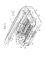
- Fig. 8 is an exploded perspective view illustrating the internal structure of the printer unit 2.
- the apparatus frame 64 is a frame that supports the various elements of the printer unit 2, and is configured of a resin that is formed as a single entity.
- the apparatus frame 64 includes: a base frame portion 64a; a pair of left and right side frame portions 64b, erected from the base frame portion 64a, that supports the various constituent elements of the transport unit 61 and the guide frame 71 with both sides; a pair of left and right front frame portions 64c that supports the front of the scanner unit 3 and supports the operation unit 63 on the front of the base frame portion 64a; and a pair of left and right rear frame portions 64d that supports the printer unit 2 in an openable and closable state via the hinge portion 4 on the rear of the base frame portion 64a.
- the front frame portions 64c each include a pair of reinforcing support portions 135 that receives the front area of the scanner unit 3 and a pair of operation support portions 136 that supports the operation unit 63 in a tiltable manner.
- Each of the reinforcing support portions 135 extends upward to reach the vicinity of the upper surface of the apparatus housing 65, and includes a seating receiving portion 155 thereupon that directly receives the corresponding seating projection 24 of the stated scanner unit 3.
- Each seating receiving portion 155 is formed as a recess, in an inverted conical trapezoidal shape that has a shape complimentary to that of the corresponding seating projection 24, and the seating projections 24 are seated thereon by fitting therewith.
- the pair of seating receiving portions 155 in the pair of reinforcing support portions 135 is formed so that one is circular when viewed from above and the other is formed as a rectangle with rounded corners that extends to the left and right (see Fig. 6 ). This allows for the error in the positional precision between the seating projections 24.
- the rear frame portions 64d include a pair of lower hinge portions 181 (first attachment portions) that configures part of the hinge portion 4, and a pair of hinge pins 183 that links the pair of lower hinge portions 181 to a pair of upper hinge portions 182, mentioned later, that is provided in the scanner unit 3.
- the apparatus housing 65 includes a pair of left and right side housings 161 that configures left and right sheathings of the printer unit 2, and a linking housing 162 that links the pair of side housings 161 at the location of the aforementioned guide frame 71.
- Each of the side housings 161 is formed of a side surface plate portion 163, having a sideways U shape when viewed from above, that covers the front, left, right, and rear surfaces, and an upper plate portion (plate portion) 164 that covers the upper surface; these portions are formed as a single entity.
- the pair of side housings 161 is configured so as to attach to the apparatus frame 64 from the left and right.
- the two upper plate portions 164 are formed in a shape of a square with one side open when viewed from above, and are disposed so as to be separated from each other in the width direction (the Y axis direction) of the complex machine 1.
- the upper surface opening 10 of the apparatus housing 65 is formed by the region enclosed by the pair of upper plate portions 164 and the linking housing 162.
- a rear opening 9 is formed on the rear of the linking housing 162.
- the rear opening 9 is configured of a paper opening with the paper tray 91 for supplying the recording medium to the interior of the apparatus, and a pair of hinge openings, which are provided on the left and right sides of the paper opening, for disposing the hinge portion 4.
- the "upper plate” referred to in the claims is configured of the two upper plate portions 164.
- Fig. 9 is a cross-sectional view of the vicinity of the hinge portion 4, seen from the side.
- Fig. 10 is a diagram illustrating the vicinity of the seating projection 24 when the scanner unit 3 is in the closed state.
- the pair of left and right upper hinge portions (second attachment portions) 182 (see Fig. 9 ) formed integrally with the upper case 17, and the pair of left and right seating projections 24 (see Fig. 10 ) projecting from the lower surface of the allowance recess 23 in the lower case 16, are provided in the upper frame 11.
- the pair of upper hinge portions 182 configures, along with the aforementioned pair of lower hinge portions 181 and the pair of hinge pins 183, the hinge portion 4 that links the printer unit 2 and the scanner unit 3 in a pivotable state.
- each seating projection 24 is disposed so as to be parallel in the Y axis direction directly below the trajectory of the center of gravity of the moving sensor carriage 32; each seating projection 24 is formed in an inverse conical trapezoidal shape, and is formed integrally with the lower case 16. In other words, when the scanner unit 3 is closed, each seating projection 24 fits into the corresponding seating receiving portion 155 of the front frame portion 64c (the reinforcing support portion 135) via the seating opening 172 in the upper plate portion 164.
- the pair of seating projections 24 fits into the pair of seating openings 172, and is seated upon the respective seating receiving portions 155 of the pair of reinforcing support portions 135.
- the pair of seating projections 24 is directly supported by the pair of reinforcing support portions 135.
- the reinforcing support portions 135 receive and directly support the seating projections 24 of the scanner unit 3; accordingly, the moment load of the scanner unit 3, whose support point is the hinge portion 4 (that is, the weight of the scanner unit 3), can be directly supported by the reinforcing support portions 135. Accordingly, the scanner unit 3 can be supported in a favorable manner.
- the seating projections 24 fit into the seating openings 172 formed in the upper plate portions 164, the moment load of the scanner unit 3 is not exerted on the upper plate portion 164, and thus the upper plate portion 164 does not bend.
- each upper plate portion 164 has a seating portion 211 instead of the seating opening 172.
- Each seating portion 211 has a ring-shaped projection 212 that surrounds the corresponding seated seating projection 24.
- each reinforcing support portion 135 is disposed below the corresponding seating portion 211, and a contact portion 213 that makes contact so as to support the corresponding upper plate portion 164 from below is formed in the upper surface thereof.
- each reinforcing support portion 135 is disposed (formed) so as to block the corresponding upper plate portion 164 from bending.
- the reinforcing support portions 135, which serve as support structures for the moment load of the scanner unit 3 support the upper plate portions 164 so as to block the upper plate portions 164 from bending, and thus the upper plate portions 164 can be effectively prevented from bending. Accordingly, the scanner unit 3 can be supported in a favorable manner by the upper plate portions 164 of the printer unit 2.
- the configuration in this embodiment is such that the seating projections 24 are formed so as to extend (project) from the lowermost area of the allowance recess 23 in the lower case 16, and the seating is carried out on these projecting portions
- the configuration may be such that the lowermost area of the allowance projecting portion 23 itself is used as the seating projections 24; in other words, the projecting portions may be omitted, and the seating may be carried out directly on the lower surfaces of the lowermost area of the allowance projecting portion 23.
- providing the seating projections 24 so as to project from the lowermost area of the allowance recess 23, as in this embodiment makes it possible to adjust the height using a method for shaving down the seating projections 24, which makes it easy to make subtle adjustments to the height thereof.
- the ring-shaped projections 212 that extend (project) from the upper plate portions 64 are provided in this embodiment; however, the configuration may be such that such ring-shaped projections 212 that project are not provided.
- the contact portions 213 extend (project) from the reinforcing support portions 135 in this embodiment, the contact portions 213 are also not absolutely necessary; the configuration may be such that the contact portions 213 are omitted, and the support is carried out directly by the reinforcing support portions 135 (that is, the upper surfaces thereof).
- the contact portions 213 are not provided, the area of contact with the upper plate portions 164 is widened, and thus a corresponding degree of precision in the components is necessary; on the other hand, providing the contact portions 213 makes it possible to adjust the height using a method for shaving down the contact portions 213, as is the case with the aforementioned seating projections 24, which makes it easy to make subtle adjustments to the height thereof.
- the scanner unit 3 can be supported in a favorable manner without the upper plate portions 164 bending, by using the stated support structure for the moment load. Accordingly, it is not necessary to consider interference with the inner units caused by bending in the upper plate portions 164, which makes it possible to suppress the apparatus as a whole from increasing in size.
- the reinforcing support portion 135 of part of the apparatus frame 64 by configuring the reinforcing support portion 135 of part of the apparatus frame 64, and thus configuring the apparatus frame 64 from a resin formed as a single entity, the number of components can be reduced, and the force received by the reinforcing support portion 135 can be dissipated appropriately.
- the force received by the hinge portion 4 can be dissipated appropriately.
- the center of gravity of the sensor carriage 32 is the center of the weight of the sensor carriage 32 including the various members mounted thereon.
- the configuration may be such that the seating projections 24 are disposed directly below the trajectory of the center of gravity of that member.
- the seating projections 24 are formed of inverted conical trapezoidal shapes and the seating receiving portions 155 are formed of shapes that are complementary to those of the seating projections 24, and the seating projections 24 fit into the seating receiving portions 155 while being guided thereby when the scanner unit 3 is closed; accordingly, the scanner unit 3 can be closed in a state in which the scanner unit 3 is positioned relative to the printer unit 2, and positional skew (looseness) in the depth direction and the width direction of the scanner unit 3 can be effectively prevented when the scanner unit 3 is in a closed state.
- pairs of the seating openings 172, reinforcing support portions 135, and seating projections 24 are provided corresponding to the two upper plate portions 164, and the positions of the upper plate portions 164 in the depth direction and the width direction are regulated through the scanner unit 3 as a result of the pair of seating projections 24 and the pair of seating openings 172 inserted thereto operating together; accordingly, it is possible to suppress problems in which the relative positions of the upper plate portions 164 become further apart from each other or closer to each other due to heat deformation, external forces, or the like.
- the ring-shaped projections 212 are provided, and the positions of the seating projections 24 on the upper plate portions 164 are regulated by the ring-shaped projections 212; accordingly, positional skew (looseness) in the depth direction and the width direction of the scanner unit 3 can be prevented.
- the configuration is such that a pair of seating projections 24 is provided in parallel in the width direction (the axial direction of the hinge portion 4) in the aforementioned embodiments, it should be noted that the configuration may be such that only one seating projection 24 is provided, or three or more seating projections 24 are provided. In this case, a corresponding number of reinforcing support portions 135, seating openings 172, seating portions 211, and so on are provided as well.
- reinforcing support portions 135 are configured of parts of the apparatus frame 64 in the aforementioned embodiments, the configuration may be such that reinforcing support portions 135 that are separate entities from the apparatus frame 64 are employed.
- the invention is applied in the complex machine 1 that includes the printer unit 2 and the scanner unit 3 in the aforementioned embodiments, the invention is not limited thereto, and may be applied in any complex apparatus as long as that complex apparatus includes a first device and a second device, such as a complex apparatus including a copy machine and a facsimile device, and so on.
- the seating projections 24 may be configured of elastic members (such as elastic rubber members).
Landscapes
- Engineering & Computer Science (AREA)
- Multimedia (AREA)
- Signal Processing (AREA)
- Facsimiles In General (AREA)
- Accessory Devices And Overall Control Thereof (AREA)
- Ink Jet (AREA)
- Facsimile Scanning Arrangements (AREA)
Applications Claiming Priority (2)
| Application Number | Priority Date | Filing Date | Title |
|---|---|---|---|
| JP2010254591 | 2010-11-15 | ||
| PCT/JP2011/006311 WO2012066758A1 (fr) | 2010-11-15 | 2011-11-11 | Dispositif combiné |
Publications (2)
| Publication Number | Publication Date |
|---|---|
| EP2642736A1 true EP2642736A1 (fr) | 2013-09-25 |
| EP2642736A4 EP2642736A4 (fr) | 2014-11-19 |
Family
ID=46047519
Family Applications (1)
| Application Number | Title | Priority Date | Filing Date |
|---|---|---|---|
| EP11840797.2A Withdrawn EP2642736A4 (fr) | 2010-11-15 | 2011-11-11 | Dispositif combiné |
Country Status (8)
| Country | Link |
|---|---|
| US (1) | US8564852B2 (fr) |
| EP (1) | EP2642736A4 (fr) |
| JP (1) | JP5633575B2 (fr) |
| CN (2) | CN104836935B (fr) |
| BR (1) | BR112013012751A2 (fr) |
| RU (1) | RU2536803C1 (fr) |
| TW (1) | TWI546203B (fr) |
| WO (1) | WO2012066758A1 (fr) |
Families Citing this family (11)
| Publication number | Priority date | Publication date | Assignee | Title |
|---|---|---|---|---|
| JP5652103B2 (ja) * | 2010-10-08 | 2015-01-14 | セイコーエプソン株式会社 | 画像読取装置 |
| JP2012185674A (ja) * | 2011-03-04 | 2012-09-27 | Toshiba Tec Corp | 印刷装置および印刷装置の書込方法 |
| JP6064395B2 (ja) | 2012-07-06 | 2017-01-25 | セイコーエプソン株式会社 | 記録装置 |
| JP5962469B2 (ja) * | 2012-11-30 | 2016-08-03 | ブラザー工業株式会社 | 画像読取装置 |
| JP6206166B2 (ja) * | 2013-12-24 | 2017-10-04 | ブラザー工業株式会社 | 画像形成装置 |
| TWD166688S (zh) * | 2014-03-10 | 2015-03-21 | 虹光精密工業股份有限公司 | 掃描器 |
| WO2016021171A1 (fr) * | 2014-08-05 | 2016-02-11 | セイコーエプソン株式会社 | Dispositif composite |
| JP6740637B2 (ja) * | 2016-02-29 | 2020-08-19 | ブラザー工業株式会社 | 画像処理装置 |
| JP6838697B2 (ja) * | 2016-09-30 | 2021-03-03 | セイコーエプソン株式会社 | 記録装置 |
| USD929995S1 (en) * | 2020-03-31 | 2021-09-07 | Avision Inc. | Scanner |
| USD950553S1 (en) * | 2020-11-17 | 2022-05-03 | Avision Inc. | Scanner |
Citations (6)
| Publication number | Priority date | Publication date | Assignee | Title |
|---|---|---|---|---|
| JP2002144673A (ja) * | 2000-11-13 | 2002-05-22 | Seiko Epson Corp | 画像入出力装置 |
| US20030056324A1 (en) * | 2001-09-27 | 2003-03-27 | Brother Kogyo Kabushiki Kaisha | Opening and closing mechanism of hinged pair of bodies |
| US20060103068A1 (en) * | 2004-11-05 | 2006-05-18 | Canon Kabushiki Kaisha | Sheet conveying apparatus and image forming apparatus |
| US20070201111A1 (en) * | 2006-02-27 | 2007-08-30 | Brother Kogyo Kabushiki Kaisha | Scanner |
| US20070292159A1 (en) * | 2006-06-19 | 2007-12-20 | Brother Kogyo Kabushiki Kaisha | Opening and closing assembly, and multifunction device including the assembly |
| US20080145098A1 (en) * | 2006-12-19 | 2008-06-19 | Brother Kogyo Kabushiki Kaisha | Image forming apparatus |
Family Cites Families (18)
| Publication number | Priority date | Publication date | Assignee | Title |
|---|---|---|---|---|
| JP3673018B2 (ja) * | 1996-06-11 | 2005-07-20 | 株式会社沖データ | 印刷装置 |
| JP3643714B2 (ja) * | 1998-10-28 | 2005-04-27 | 株式会社リコー | 画像形成装置 |
| JP2000347315A (ja) * | 1999-06-08 | 2000-12-15 | Sharp Corp | 画像形成装置および画像形成装置の製造方法 |
| JP3913141B2 (ja) * | 2002-08-21 | 2007-05-09 | キヤノン株式会社 | 記録装置 |
| JP4407803B2 (ja) * | 2004-03-08 | 2010-02-03 | ブラザー工業株式会社 | 画像記録装置 |
| JP4429856B2 (ja) * | 2004-09-29 | 2010-03-10 | ブラザー工業株式会社 | 記録媒体搬送装置、画像形成装置 |
| JP4375552B2 (ja) * | 2004-07-28 | 2009-12-02 | ブラザー工業株式会社 | 画像記録装置 |
| US7631965B2 (en) * | 2005-02-28 | 2009-12-15 | Brother Kogyo Kabushiki Kaisha | Image-recording device having movable carriage to which flexible flat cable and flexible ink supply tubes are connected |
| JP4612872B2 (ja) * | 2005-06-30 | 2011-01-12 | キヤノン株式会社 | 給紙装置、並びに記録装置及び画像読取装置 |
| JP4740665B2 (ja) * | 2005-07-05 | 2011-08-03 | オリンパス株式会社 | 画像記録装置 |
| JP2007049272A (ja) * | 2005-08-08 | 2007-02-22 | Ricoh Co Ltd | 画像読取装置、画像形成装置 |
| JP2007201642A (ja) * | 2006-01-24 | 2007-08-09 | Kyocera Mita Corp | 画像読取装置およびそれを備える画像形成装置 |
| JP4763625B2 (ja) * | 2006-01-27 | 2011-08-31 | 京セラミタ株式会社 | 画像形成装置及び複合機器 |
| US7733540B2 (en) * | 2006-03-24 | 2010-06-08 | Brother Kogyo Kabushiki Kaisha | Multifunction apparatus |
| JP4389177B2 (ja) * | 2006-10-26 | 2009-12-24 | ブラザー工業株式会社 | 画像形成装置 |
| JP4868164B2 (ja) * | 2007-09-28 | 2012-02-01 | ブラザー工業株式会社 | 給紙トレイ、給紙装置、及びそれを備えた画像記録装置 |
| JP5262471B2 (ja) * | 2008-09-05 | 2013-08-14 | セイコーエプソン株式会社 | 記録装置及び記録装置におけるトレイ制御方法 |
| JP4853538B2 (ja) * | 2009-03-17 | 2012-01-11 | 富士ゼロックス株式会社 | 画像読取装置 |
-
2011
- 2011-11-11 TW TW100141340A patent/TWI546203B/zh active
- 2011-11-11 CN CN201510214308.0A patent/CN104836935B/zh active Active
- 2011-11-11 RU RU2013127190/07A patent/RU2536803C1/ru active
- 2011-11-11 CN CN2011800548769A patent/CN103210635A/zh active Pending
- 2011-11-11 EP EP11840797.2A patent/EP2642736A4/fr not_active Withdrawn
- 2011-11-11 BR BR112013012751A patent/BR112013012751A2/pt not_active Application Discontinuation
- 2011-11-11 JP JP2012544103A patent/JP5633575B2/ja active Active
- 2011-11-11 WO PCT/JP2011/006311 patent/WO2012066758A1/fr active Application Filing
- 2011-11-14 US US13/296,083 patent/US8564852B2/en active Active
Patent Citations (6)
| Publication number | Priority date | Publication date | Assignee | Title |
|---|---|---|---|---|
| JP2002144673A (ja) * | 2000-11-13 | 2002-05-22 | Seiko Epson Corp | 画像入出力装置 |
| US20030056324A1 (en) * | 2001-09-27 | 2003-03-27 | Brother Kogyo Kabushiki Kaisha | Opening and closing mechanism of hinged pair of bodies |
| US20060103068A1 (en) * | 2004-11-05 | 2006-05-18 | Canon Kabushiki Kaisha | Sheet conveying apparatus and image forming apparatus |
| US20070201111A1 (en) * | 2006-02-27 | 2007-08-30 | Brother Kogyo Kabushiki Kaisha | Scanner |
| US20070292159A1 (en) * | 2006-06-19 | 2007-12-20 | Brother Kogyo Kabushiki Kaisha | Opening and closing assembly, and multifunction device including the assembly |
| US20080145098A1 (en) * | 2006-12-19 | 2008-06-19 | Brother Kogyo Kabushiki Kaisha | Image forming apparatus |
Non-Patent Citations (1)
| Title |
|---|
| See also references of WO2012066758A1 * |
Also Published As
| Publication number | Publication date |
|---|---|
| CN104836935B (zh) | 2018-10-02 |
| JP5633575B2 (ja) | 2014-12-03 |
| RU2013127190A (ru) | 2014-12-27 |
| TWI546203B (zh) | 2016-08-21 |
| BR112013012751A2 (pt) | 2018-05-02 |
| US20120120461A1 (en) | 2012-05-17 |
| CN103210635A (zh) | 2013-07-17 |
| US8564852B2 (en) | 2013-10-22 |
| TW201223780A (en) | 2012-06-16 |
| EP2642736A4 (fr) | 2014-11-19 |
| JPWO2012066758A1 (ja) | 2014-05-12 |
| RU2536803C1 (ru) | 2014-12-27 |
| CN104836935A (zh) | 2015-08-12 |
| WO2012066758A1 (fr) | 2012-05-24 |
Similar Documents
| Publication | Publication Date | Title |
|---|---|---|
| EP2642736A1 (fr) | Dispositif combiné | |
| EP1574351B1 (fr) | Appareil d'impression d'image | |
| US9315031B2 (en) | Ink jet recording apparatus | |
| US7654515B2 (en) | Image forming device with two attached cassettes and one transportation device | |
| US6132122A (en) | Low profile architecture for internet appliance printing | |
| US20070201111A1 (en) | Scanner | |
| US7431279B2 (en) | Media support for an imaging apparatus | |
| US9233549B2 (en) | Recording apparatus | |
| RU2590885C2 (ru) | Жидкостной эжекционный аппарат | |
| US9264562B2 (en) | Recording apparatus | |
| JP3767568B2 (ja) | 画像形成装置 | |
| JP5991462B2 (ja) | 記録装置 | |
| JP2021160228A (ja) | 印刷装置 | |
| JP7296030B2 (ja) | 画像読取装置および画像形成装置 | |
| US20120001993A1 (en) | Image Forming Device | |
| JP2012109703A (ja) | 校正基準器並びに、これを備えた画像読取装置および複合機 | |
| JP6439721B2 (ja) | 液体噴射装置 | |
| EP3608117B1 (fr) | Imprimante à jet d'encre | |
| JP2012101501A (ja) | 画像記録装置およびこれを備えた複合機 | |
| JP6439720B2 (ja) | 液体噴射装置 | |
| JP2012192548A (ja) | 記録装置 | |
| JPH08258371A (ja) | 電子機器 | |
| US20050134885A1 (en) | Image scanning apparatus | |
| JP2017154400A (ja) | 記録装置 | |
| JP2002326422A (ja) | 記録装置 |
Legal Events
| Date | Code | Title | Description |
|---|---|---|---|
| PUAI | Public reference made under article 153(3) epc to a published international application that has entered the european phase |
Free format text: ORIGINAL CODE: 0009012 |
|
| 17P | Request for examination filed |
Effective date: 20130522 |
|
| AK | Designated contracting states |
Kind code of ref document: A1 Designated state(s): AL AT BE BG CH CY CZ DE DK EE ES FI FR GB GR HR HU IE IS IT LI LT LU LV MC MK MT NL NO PL PT RO RS SE SI SK SM TR |
|
| DAX | Request for extension of the european patent (deleted) | ||
| A4 | Supplementary search report drawn up and despatched |
Effective date: 20141017 |
|
| RIC1 | Information provided on ipc code assigned before grant |
Ipc: H04N 1/193 20060101ALI20141013BHEP Ipc: H04N 1/12 20060101ALI20141013BHEP Ipc: H04N 1/10 20060101ALI20141013BHEP Ipc: H04N 1/00 20060101AFI20141013BHEP |
|
| STAA | Information on the status of an ep patent application or granted ep patent |
Free format text: STATUS: THE APPLICATION IS DEEMED TO BE WITHDRAWN |
|
| 18D | Application deemed to be withdrawn |
Effective date: 20150516 |