EP2635743B1 - Spannklemme zum befestigen einer schiene und system - Google Patents
Spannklemme zum befestigen einer schiene und system Download PDFInfo
- Publication number
- EP2635743B1 EP2635743B1 EP11776140.3A EP11776140A EP2635743B1 EP 2635743 B1 EP2635743 B1 EP 2635743B1 EP 11776140 A EP11776140 A EP 11776140A EP 2635743 B1 EP2635743 B1 EP 2635743B1
- Authority
- EP
- European Patent Office
- Prior art keywords
- rail
- section
- tension clamp
- torsion
- sections
- Prior art date
- Legal status (The legal status is an assumption and is not a legal conclusion. Google has not performed a legal analysis and makes no representation as to the accuracy of the status listed.)
- Active
Links
- 230000007704 transition Effects 0.000 claims description 15
- 238000006073 displacement reaction Methods 0.000 description 6
- 229910000639 Spring steel Inorganic materials 0.000 description 5
- 239000000758 substrate Substances 0.000 description 4
- 238000005452 bending Methods 0.000 description 2
- 238000004519 manufacturing process Methods 0.000 description 2
- 230000001419 dependent effect Effects 0.000 description 1
- 230000000694 effects Effects 0.000 description 1
- 230000002996 emotional effect Effects 0.000 description 1
- 230000008092 positive effect Effects 0.000 description 1
- 238000007493 shaping process Methods 0.000 description 1
Images


Classifications
-
- E—FIXED CONSTRUCTIONS
- E01—CONSTRUCTION OF ROADS, RAILWAYS, OR BRIDGES
- E01B—PERMANENT WAY; PERMANENT-WAY TOOLS; MACHINES FOR MAKING RAILWAYS OF ALL KINDS
- E01B9/00—Fastening rails on sleepers, or the like
- E01B9/02—Fastening rails, tie-plates, or chairs directly on sleepers or foundations; Means therefor
- E01B9/28—Fastening on wooden or concrete sleepers or on masonry with clamp members
- E01B9/30—Fastening on wooden or concrete sleepers or on masonry with clamp members by resilient steel clips
- E01B9/303—Fastening on wooden or concrete sleepers or on masonry with clamp members by resilient steel clips the clip being a shaped bar
Definitions
- the invention relates to a tension clamp for securing a rail according to the preamble of claim 1.
- Clamps of this type are usually bent in one piece from a spring steel.
- the invention relates to a system for fastening a rail, which has a rail, a standing bridge and a rail head, with a guide plate, a clamp held on the guide plate and a clamping means for clamping the clamp against a rail supporting the base.
- Rail systems and clamps of the type described above, for example in the US patent US 3,690,551 A or the US 3,439,874 A described.
- the holding arms of the known from these patents ⁇ -shaped clamping clamps have seen in plan a curved course with end portions, the End faces are directed against each other. In this case, the end portions may be curved or rectilinear, formed parallel to the respective associated torsion portion of the tension clamp.
- the free ends of the retaining arms lie on the rail of the rail to be fastened.
- the middle part of the tensioning clamp wraps around the shaft of the fastening screw.
- a tension clamp is used as a spring element for generating the required for holding down the rail resilient elastic holding force, which is designed taking into account the longitudinal direction of the rail to be fastened length of the support plate so that its at least one support arm can travel maximum spring travel.
- the end portion of the support arm is angled away from the torsion section in such a way that, in the assembly position, it points in the direction of the web of the rail to be fastened.
- the displacement of the support area in the direction of the rail web causes a higher resistance to undesired rotation, whereby in particular the correct position mounting of the tension clamp is facilitated.
- the object of the invention was to provide a tensioning clamp and a system for fastening a rail, which are capable of high fatigue strength are to apply large hold-down forces and at the same time it is ensured that even with increasing wear of the rail fastening still sufficiently high hold-down forces act on the rail.
- a tension clamp this object has been achieved according to the invention in that such a tension clamp has the features specified in claim 1.
- a tensioning clamp according to the invention for fastening a rail is mirror-symmetrical and, in accordance with the prior art described above, has a loop-shaped middle section, from which two oppositely directed torsion sections depart, to which a respective retaining arm extends at each of its free ends via a respective transition section connected to an end section. In use, the tension clamp is supported on the rail foot of the respective rail to be fastened via the end sections.
- the retaining arms of the tensioning clamp are then continuously curved at least in a curve section extending to the free end of its end sections such that the end sections of the retaining arms point in the direction of the middle section and the longitudinal axis of the torsion section assigned to the respective retaining arm, as seen in plan view of the tensioning clamp.
- the end section present on the respective retaining arm is bent in the installed position away from the rail web of the rail to be fastened in the direction of the longitudinal axis of the torsion section of the tensioning clamp assigned to the respective retaining arm.
- the bending of the curved section with the end section of the retaining arm is preferably not restricted to a bending in one plane. Rather, the bend is advantageously carried out in three spatial directions. In this way, at the respective end portion form a narrow, approximately point-shaped bearing surface over which the end portion is supported in use on the foot of the rail to be fastened in use.
- bent end portion existing bearing surface over which a tension clamp according to the invention is supported in use on the surface of the rail is thus displaced in a tension clamp according to the invention to a position which is transverse to the respective holding arm associated torsion has measured to the longitudinal extent of the rail distance, which is seen in plan view from above on the tension clamp is smaller than the largest also transverse to the longitudinal extent of the Rail measured distance.
- the bent to its free end running arm of a tensioning clamp according to the invention therefore has an overall increased length due to its in use in the direction of the web of the rail to be fastened to the support surface projecting arc from Torsionsabrough to the bearing surface of its end portion relative to the conventional clamps.
- the support arms are able to accommodate high alternating loads without the risk of damage. Accordingly, with a tensioning clamp according to the invention, large hold-down forces can be applied with optimized fatigue strength of the tensioning clamp.
- the tension clamp does not press any more with the bearing surface of the respective one loaded in the new state End section on the rail, however, is ensured by bent in the direction of the Torsionsabterrorisms the tension clamp or its imaginary extension or longitudinal axis shape of the end portion that the tensioning clamp still acts safely on the rail in this situation.
- the tension clamp "rolls" during a displacement of the rail with its curved end portion on the rail from, with the result that shifts according to the wear-related displacement of the rail and the bearing surface over which the end portion acts on the rail.
- this effect occurs when the end portion is bent in three directions in space, so sitting in use only over a narrow, approximately point-like bearing surface on the rail, this effect occurs.
- the holding arm of a tension clamp according to the invention Due to the guided in a comparatively wide arc shape of its curve section, the holding arm of a tension clamp according to the invention has an increased length. This leads to a greater elasticity of the support arm and concomitantly to a less heavy load, with the result that its fatigue strength is increased.
- a holding arm according to the invention, only the end-side, the respective end portion comprehensive curve portion is continuously bent, while the holding arm is formed in at least one other section in a straight line, for example, to bridge large distances.
- the holding arm according to another embodiment is executed overall as a continuously curved curve section, can be used in the holding arm to reduce stresses, so that a maximum continuous load capacity is achieved. At the same time a simple manufacture of the tension clamp is possible with this design.
- the support arm can be shaped so that it is only minimally deformed during the bracing. This makes it possible to align the end portion of the support arm with respect to the rest of its portion from the outset so that it sits already on a relaxed tension clamp on the surface of the rail foot.
- the shape and orientation of the support arm is chosen so that the support arm largely exclusively serves as a lever with low inherent elasticity, so that the force exerted by the tension clamp in the tensioned state spring force is generated substantially exclusively by torsion of Torsionsabitess.
- the holding arm is aligned with respect to the torsion portion so that the torsion portion and the holding arm in an overhead view of the tension clamp from above seen an angle of 80 ° - 110 °, in particular 85 ° - 95 ° , wherein in the context of manufacturing capabilities at 90 ° approximated included angle brings optimal results.
- the stiffness of the support arm can be optimized by an arcuate portion of the support arm extends in a plane that penetrates the torsion at an angle of 80 ° - 100 °.
- this alignment of the arcuate portion of the support arm can be realized in that the transition portion between the support arm and the torsion portion describes a lying on a horizontal surface tension clamp upward arc, which comprises an angular range of 80 ° - 110 °.
- the support arm in side view in the region of this section on a bow or dome-shaped shape is ensured by the fact that the support arm even under high resilient hold-down forces or in the case of a transverse displacement of the rail Maintains shape essentially unchanged. As a result, its end portion in the tensioned state is always optimal on the rail.
- the concentration of the generation of the hold-down force on the torsion portion can be further assisted by including the center portion with the torsion portion at an angle of 80 ° -110 ° when viewed in plan.
- the central portion acts essentially exclusively as a lever for the torsion of the torsion without being resilient itself.
- Tensioning clamps according to the invention can, like the tensioning clamps known from the prior art, be manufactured in one piece from a spring steel wire by forming a curved curve bent without a jump.
- the storage and handling of a tensioning clamp according to the invention can be simplified in a conventional manner in that the distance of the free end of the bent end portion to the central portion is smaller than the smallest thickness of the central portion, Torsionsabitess, transition section, support arms and end portion. In this way, it can be safely prevented that loosely clamped clamps interlock with each other.
- the tensioning clamp according to the invention is mirror-symmetrical in that the middle section is loop-shaped and two torsion sections oriented opposite to it depart, to which a respective retaining arm with a bent end section is connected via a respective transition section.
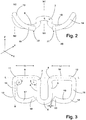
- the tension clamp according to the invention then has a W or ⁇ -shaped configuration.
- the present invention sought concentration of the generation of the resilient hold-down force on the Torsionsabites allows a particularly space-saving design of a tension clamp according to the invention.
- the length of the Torsionsarms is in each case so short dimensioned that the respective support arm is guided at least in sections above the guide plate.
- a concrete sill U supported rail S is designed mirror-symmetrically with respect to a normal to the footprint 2 of the ground U aligned plane N1. It has a loop-shaped, in plan view ( Fig. 4 ) U-shaped central portion 3, with two parallel and spaced apart aligned legs 4.5 and a leg connecting the 4.5 together, the rail foot F to be fastened rail S associated semi-circular connecting portion 6.
- one of the legs 4, 5 of the middle section 3 is connected in each case to a transition section 7, 8 which is bent through 90 °, and a respective torsion section 9, 10 which extends in the lateral direction.
- the torsion sections 9, 10 in this case point away in opposite directions from the middle section 3 and, viewed in plan view, in each case enclose an angle ⁇ of approximately 90 ° with the respectively assigned leg 4, 5 of the middle section.
- a further transition section 11, 12 is connected in each case, which in the case of the tension clamp 1 (1) located on its underside.
- Fig. 1 . 2 in a circular arc, which comprises an angle of about 90 °, leads upwards.
- transition sections 11, 12 pass over at their end facing away from the respective torsion section 9, 10, in each case into a continuously bent retaining arm 13, 14. by virtue of their continuously bent in the three spatial directions X, Y, Z form the holding arms 13,14 as such each represents a single curve section.
- the connected to the respective transition section 11,12 sections 15,16 of the support arms close in plan view, each with the associated Torsion section 9,10 an angle ⁇ of about 90 °, so that they are aligned in a plan view substantially parallel to the legs 4,5 of the central portion 3.
- the center axis M of the respective section 15,16 of the support arms 13,14 accordingly runs in a plane N2, which is pierced by the common longitudinal axis L of the torsion sections 9, 10 each at an angle of approximately 90 ° +/- 5 °.
- the sections 15,16 of the support arms 13,14 are bent in the manner of a dome strut and embrace an angular range of about 180 °.
- the sections 15, 16 of the holding arms 13, 14 each extend in an end section 19, 20 in each case through an approximately 90 ° in the direction of the central section 3 and downwards transition section 17, 18 ,
- These end portions 19,20 are seen in plan view ( Fig. 3 ) as a continuation of the transition sections 17,18 each further in the direction of the longitudinal axis L of the torsion 9,10 and in the direction of the central portion 3 in the three spatial directions X, Y, Z bent so that they lie on a flat surface, respectively are supported with a narrow, approximately point-shaped bearing surface 21,22 on the surface in question.
- the length and curvature of the end portions 19, 20 is in consideration of the length of substantially parallel to the legs 4, 5 of the central portion 3 extending portions 15,16 of the holding arms 13,14 in each case chosen so that the end portions 19,20 terminate at a distance a to the connecting portion 6 of the central portion 3, which is smaller than the smallest thickness d of the spring steel, from which the tension clamp. 1 is bent.
- the clear width of the existing between the central portion 3 and the end portions 19,20 distance is therefore so small that no other tensioning clamp 1 can pass through this distance.
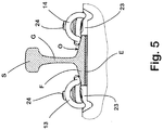
- the guide plate 23 is formed in the embodiment described here in the manner of a conventional angled guide plate and has on its subsurface U associated underside on their measured in the longitudinal direction of the rail S width B extending paragraph, which is located in mounting position befindaji guide plate 23 in a correspondingly shaped , in the underground U provided channel sits.
- the guide plate 23 in the assembly position, is supported in each case with its rear side facing away from the rail S on a shoulder likewise formed on the substrate U.
- the guide plate 23 At its rail F associated, opposite the rear side widened front side, the guide plate 23 each have a contact surface against which the rail foot F is supported with its longitudinal edge. From the rail S when driving over by a rail vehicle not shown here transverse forces are absorbed by the guide plate 23 and discharged into the substrate U.
- the guide plate 23 at its top Adjacent to its rear side, the guide plate 23 at its top in each case a parallel to the contact surface of the guide plate 23 extending groove and additional elements not shown here in detail for guiding the mounted on the guide plate 23 each tension clamp 1 and also not visible here, of the Upper side to the underground U leading through opening, through which the clamping screw 24 is inserted.
- the clamping screw 24 is in each case screwed into a submerged in the underground U, not visible here dowel.
- the length of the legs 4, 5 of the middle section 3 is dimensioned such that the tensioning clamp 1 can be seated in a preassembly position, although its already screwed in, but not yet fully tightened, in which its torsion sections 9, 10 move in the direction of the rear side of the guide plate 23 added are arranged outside of their associated groove of the guide plate 23, that the bent end portions 19,20 of the tension clamp 1 no longer protrude in the space provided for the rail S area.
- the tension clamps 1 can then be pushed from their preassembly position into the final assembly position, in which they are deflected with their end sections 19 bent away from the web G of the rail S, 20 on the top O of the rail foot F rest. Subsequently, the respective clamping screw 24 is tightened. In this case, the central portion 3 of the clamps 1 is moved in each case in the direction of the substrate U. Since the retaining arms 13,14 are substantially rigidly supported on the rail foot F at the same time, in the course of tightening the tension clamps 1, essentially only their torsion sections 9, 10 are twisted. As a result, so high spring forces for elastic hold down the rail S are available.
- an elastic layer E can be provided between the rail F and the ground in a conventional manner.
- the measured transversely to the longitudinal extent of the rail S and the longitudinal axis L length Lh of the support arms 13,14 is such that in the new state with completely assembled system S1, S2, the smallest distance w between the axis parallel to the longitudinal axis L extending respective torsion portion 9,10 and the respective associated end portion 19,20 is greater than the distance v between the respective guide plate 23 associated edge of the rail foot F and the respective torsion 9,10. In this dimensioning of the holding arms 13,14 ensures that the end portions 19,20 are always safely supported on the rail foot F.
- the rail S is displaced relative to the guide plate 23, as a result of which the originally loaded bearing surfaces 21, 22 of the end sections protrude into a gap formed between the guide plate 23 and the rail foot F, the end sections 19 are located 20 continue to rest on the rail foot F via support portions which are respectively spaced from the free end face of the end portions 19,20.
Landscapes
- Engineering & Computer Science (AREA)
- Mechanical Engineering (AREA)
- Architecture (AREA)
- Civil Engineering (AREA)
- Structural Engineering (AREA)
- Clamps And Clips (AREA)
- Railway Tracks (AREA)
- Supports For Pipes And Cables (AREA)
- Mutual Connection Of Rods And Tubes (AREA)
Priority Applications (1)
| Application Number | Priority Date | Filing Date | Title |
|---|---|---|---|
| PL11776140T PL2635743T3 (pl) | 2010-11-04 | 2011-10-17 | Zacisk mocujący do mocowania szyny i układ |
Applications Claiming Priority (2)
| Application Number | Priority Date | Filing Date | Title |
|---|---|---|---|
| DE102010050200A DE102010050200A1 (de) | 2010-11-04 | 2010-11-04 | Spannklemme zum Befestigen einer Schiene und mit einer solchen Spannklemme ausgestattetes System |
| PCT/EP2011/068134 WO2012059318A1 (de) | 2010-11-04 | 2011-10-17 | Spannklemme zum befestigen einer schiene und mit einer solchen spannklemme ausgestattetes system |
Publications (2)
| Publication Number | Publication Date |
|---|---|
| EP2635743A1 EP2635743A1 (de) | 2013-09-11 |
| EP2635743B1 true EP2635743B1 (de) | 2019-08-14 |
Family
ID=44883224
Family Applications (1)
| Application Number | Title | Priority Date | Filing Date |
|---|---|---|---|
| EP11776140.3A Active EP2635743B1 (de) | 2010-11-04 | 2011-10-17 | Spannklemme zum befestigen einer schiene und system |
Country Status (17)
| Country | Link |
|---|---|
| EP (1) | EP2635743B1 (ru) |
| JP (1) | JP5778292B2 (ru) |
| KR (1) | KR101653694B1 (ru) |
| CN (1) | CN103201430A (ru) |
| AP (1) | AP3570A (ru) |
| AU (1) | AU2011325351B2 (ru) |
| BR (1) | BR112013011066A2 (ru) |
| CA (1) | CA2815760C (ru) |
| DE (2) | DE102010050200A1 (ru) |
| EA (1) | EA021499B1 (ru) |
| ES (1) | ES2753165T3 (ru) |
| IL (1) | IL225942A0 (ru) |
| MX (1) | MX338004B (ru) |
| PL (1) | PL2635743T3 (ru) |
| SG (1) | SG189555A1 (ru) |
| UA (1) | UA109455C2 (ru) |
| WO (1) | WO2012059318A1 (ru) |
Families Citing this family (4)
| Publication number | Priority date | Publication date | Assignee | Title |
|---|---|---|---|---|
| DE102011000896A1 (de) * | 2011-02-23 | 2012-08-23 | Vossloh-Werke Gmbh | System zum Befestigen einer Schiene |
| EA025681B1 (ru) * | 2013-10-07 | 2017-01-30 | Майластейн Менеджмент Инк. | Клемма рельсового скрепления |
| PT3346054T (pt) | 2017-01-10 | 2022-01-19 | Schwihag Ag | Braçadeira de tensão e sistema de fixação de carris para a fixação de carris ferroviários |
| KR101971886B1 (ko) | 2018-12-14 | 2019-04-24 | 대원강업주식회사 | 고속철도용 레일 체결장치의 체결스프링 특성 시험 장치 및 시험 방법 |
Family Cites Families (15)
| Publication number | Priority date | Publication date | Assignee | Title |
|---|---|---|---|---|
| DE1061810B (de) * | 1957-05-14 | 1959-07-23 | Johan Frederik Deenik Dipl Ing | Befestigungsvorrichtung fuer auf starren Unterlagen zwischen seitlichen Anschlaegen liegende Eisenbahn-schienen mittels einer federnden Klemme |
| DE1261151B (de) | 1966-10-29 | 1968-02-15 | Meier Hermann Dr Ing | Schienenbefestigung mittels elastischer Klemme |
| BE757946A (fr) | 1969-10-27 | 1971-04-01 | Munch Wilhelm | Fixation de rails |
| DE3526653A1 (de) * | 1985-07-25 | 1987-02-05 | Vossloh Werke Gmbh | Schienenbefestigung mittels einer elastischen spannklemme |
| FR2621619B1 (fr) * | 1987-10-07 | 1990-03-02 | Allevard Ind Sa | Attache de fixation de rail de chemin de fer comportant des moyens d'arret de deplacement et ressort d'attache |
| JPH0757924B2 (ja) * | 1988-08-16 | 1995-06-21 | フォスロー − ベルケ・ゲーエムベーハー | 鉄道用レール固定装置 |
| DE8906790U1 (ru) * | 1989-06-02 | 1989-08-31 | Vossloh-Werke Gmbh, 5980 Werdohl, De | |
| RU2034944C1 (ru) * | 1993-04-02 | 1995-05-10 | Александр Николаевич Жученко | Клемма рельсового скрепления |
| CN2466209Y (zh) * | 2000-12-18 | 2001-12-19 | 程平 | 铁轨用道扣 |
| DE102004044869B4 (de) * | 2004-09-14 | 2013-05-08 | Voestalpine Bwg Gmbh & Co. Kg | Anordnung zum Führen einer Schiene auf einer Betonschwelle sowie Verfahren zum Herstellen einer solchen |
| DE102005048829A1 (de) * | 2004-12-09 | 2006-06-29 | SCHWIHAG GESELLSCHAFT FüR EISENBAHNOBERBAU MBH | Kraftschlüssig-elastische Schienenbefestigung für Gleisanlagen |
| ATE510067T1 (de) * | 2006-01-21 | 2011-06-15 | Vossloh Werke Gmbh | System zur befestigung einer schiene |
| DE202007018566U1 (de) * | 2007-09-14 | 2008-12-04 | Vossloh-Werke Gmbh | System zum Befestigen einer Schiene auf einem ebenen festen Untergrund |
| DE102007046543A1 (de) * | 2007-09-27 | 2009-04-16 | Vossloh-Werke Gmbh | System zum Befestigen einer Schiene und Spannklemme für ein solches System |
| CN111509794B (zh) | 2020-03-19 | 2021-09-03 | 国网浙江省电力有限公司信息通信分公司 | 一种带负载电源充放电管理系统 |
-
2010
- 2010-11-04 DE DE102010050200A patent/DE102010050200A1/de not_active Withdrawn
- 2010-11-04 DE DE202010016149U patent/DE202010016149U1/de not_active Expired - Lifetime
-
2011
- 2011-10-17 WO PCT/EP2011/068134 patent/WO2012059318A1/de active Application Filing
- 2011-10-17 EP EP11776140.3A patent/EP2635743B1/de active Active
- 2011-10-17 CN CN2011800534060A patent/CN103201430A/zh active Pending
- 2011-10-17 KR KR1020137014447A patent/KR101653694B1/ko active IP Right Grant
- 2011-10-17 JP JP2013537059A patent/JP5778292B2/ja not_active Expired - Fee Related
- 2011-10-17 AU AU2011325351A patent/AU2011325351B2/en active Active
- 2011-10-17 BR BR112013011066A patent/BR112013011066A2/pt not_active IP Right Cessation
- 2011-10-17 SG SG2013034459A patent/SG189555A1/en unknown
- 2011-10-17 PL PL11776140T patent/PL2635743T3/pl unknown
- 2011-10-17 AP AP2013006898A patent/AP3570A/xx active
- 2011-10-17 CA CA2815760A patent/CA2815760C/en active Active
- 2011-10-17 MX MX2013005063A patent/MX338004B/es active IP Right Grant
- 2011-10-17 EA EA201300427A patent/EA021499B1/ru not_active IP Right Cessation
- 2011-10-17 UA UAA201305576A patent/UA109455C2/ru unknown
- 2011-10-17 ES ES11776140T patent/ES2753165T3/es active Active
-
2013
- 2013-04-25 IL IL225942A patent/IL225942A0/en unknown
Non-Patent Citations (1)
| Title |
|---|
| None * |
Also Published As
| Publication number | Publication date |
|---|---|
| AU2011325351B2 (en) | 2015-12-03 |
| ES2753165T3 (es) | 2020-04-07 |
| MX2013005063A (es) | 2013-06-28 |
| DE202010016149U1 (de) | 2011-02-17 |
| BR112013011066A2 (pt) | 2016-08-23 |
| MX338004B (es) | 2016-03-30 |
| JP2013541655A (ja) | 2013-11-14 |
| AU2011325351A1 (en) | 2013-05-23 |
| EA201300427A1 (ru) | 2013-09-30 |
| AP2013006898A0 (en) | 2013-06-30 |
| CN103201430A (zh) | 2013-07-10 |
| AP3570A (en) | 2016-02-03 |
| WO2012059318A1 (de) | 2012-05-10 |
| EP2635743A1 (de) | 2013-09-11 |
| CA2815760A1 (en) | 2012-05-10 |
| PL2635743T3 (pl) | 2020-05-18 |
| JP5778292B2 (ja) | 2015-09-16 |
| DE102010050200A1 (de) | 2012-05-10 |
| KR20130084689A (ko) | 2013-07-25 |
| SG189555A1 (en) | 2013-06-28 |
| CA2815760C (en) | 2015-08-11 |
| KR101653694B1 (ko) | 2016-09-02 |
| UA109455C2 (uk) | 2015-08-25 |
| IL225942A0 (en) | 2013-07-31 |
| EA021499B1 (ru) | 2015-06-30 |
Similar Documents
| Publication | Publication Date | Title |
|---|---|---|
| EP2635742B1 (de) | Spannklemme zum befestigen einer schiene und mit einer solchen spannklemme ausgestattetes system | |
| EP2191069B1 (de) | System zum befestigen einer schiene und spannklemme für ein solches system | |
| EP1774101B1 (de) | System zum befestigen einer schiene für schienenfahrzeuge | |
| EP2386687B1 (de) | Führungsplatte zum seitlichen Führen einer Schiene und System zum Befestigen einer Schiene auf einem Untergrund | |
| EP1767793A2 (de) | Befestigungsvorrichtung für die Befestigung von Solarpaneelen an einer Montageschiene | |
| EP2635743B1 (de) | Spannklemme zum befestigen einer schiene und system | |
| DE112005000318B4 (de) | Kältemittelverdichter | |
| EP3315874B1 (de) | Geteilt ausgebildeter dachhaken für hohe belastungen | |
| DE2225707A1 (de) | Zweischienen-foerdersystem | |
| DE3003881A1 (de) | Spannbuegel fuer kraftschluessige und elastisch nachgiebige schienenbefestigungen mit formschluessigem seitenhalt von gleisanlagen | |
| WO2015004252A1 (de) | Unterlegplatte und schienenbefestigungspunkt | |
| DE102004033723B4 (de) | Federelement und System für die Befestigung von Schienen | |
| EP2775231B1 (de) | Montagebügel | |
| DE102009053625B4 (de) | Trägerklammer und Halteanordnung | |
| AT519566B1 (de) | Unterteil für eine Klemmvorrichtung | |
| DE7739969U1 (de) | Blattfeder | |
| DE102007062278A1 (de) | Zwinge | |
| EP3346054B1 (de) | Spannklemme und schienenbefestigungssystem zur befestigung von eisenbahnschienen | |
| EP0278101A1 (de) | Heuwerbungsmaschine | |
| DE1020589B (de) | Nachgiebige Verbindung fuer gleichsinnig ineinanderliegende geflanschte Rinnenprofile | |
| DE202019104677U1 (de) | Modulbefestigungsvorrichtung | |
| EP2123843A2 (de) | Klemmelement | |
| DE202007018308U1 (de) | System zum Befestigen einer Schiene und Spannklemme für ein solches System | |
| DE202009015756U1 (de) | Trägerklammer und Halteanordnung | |
| WO2010091671A2 (de) | Träger für den ausleger eines dachhalters |
Legal Events
| Date | Code | Title | Description |
|---|---|---|---|
| PUAI | Public reference made under article 153(3) epc to a published international application that has entered the european phase |
Free format text: ORIGINAL CODE: 0009012 |
|
| 17P | Request for examination filed |
Effective date: 20130604 |
|
| AK | Designated contracting states |
Kind code of ref document: A1 Designated state(s): AL AT BE BG CH CY CZ DE DK EE ES FI FR GB GR HR HU IE IS IT LI LT LU LV MC MK MT NL NO PL PT RO RS SE SI SK SM TR |
|
| DAX | Request for extension of the european patent (deleted) | ||
| 17Q | First examination report despatched |
Effective date: 20151022 |
|
| STAA | Information on the status of an ep patent application or granted ep patent |
Free format text: STATUS: EXAMINATION IS IN PROGRESS |
|
| GRAP | Despatch of communication of intention to grant a patent |
Free format text: ORIGINAL CODE: EPIDOSNIGR1 |
|
| STAA | Information on the status of an ep patent application or granted ep patent |
Free format text: STATUS: GRANT OF PATENT IS INTENDED |
|
| INTG | Intention to grant announced |
Effective date: 20181212 |
|
| GRAJ | Information related to disapproval of communication of intention to grant by the applicant or resumption of examination proceedings by the epo deleted |
Free format text: ORIGINAL CODE: EPIDOSDIGR1 |
|
| STAA | Information on the status of an ep patent application or granted ep patent |
Free format text: STATUS: EXAMINATION IS IN PROGRESS |
|
| GRAP | Despatch of communication of intention to grant a patent |
Free format text: ORIGINAL CODE: EPIDOSNIGR1 |
|
| STAA | Information on the status of an ep patent application or granted ep patent |
Free format text: STATUS: GRANT OF PATENT IS INTENDED |
|
| INTC | Intention to grant announced (deleted) | ||
| INTG | Intention to grant announced |
Effective date: 20190227 |
|
| GRAS | Grant fee paid |
Free format text: ORIGINAL CODE: EPIDOSNIGR3 |
|
| GRAA | (expected) grant |
Free format text: ORIGINAL CODE: 0009210 |
|
| STAA | Information on the status of an ep patent application or granted ep patent |
Free format text: STATUS: THE PATENT HAS BEEN GRANTED |
|
| AK | Designated contracting states |
Kind code of ref document: B1 Designated state(s): AL AT BE BG CH CY CZ DE DK EE ES FI FR GB GR HR HU IE IS IT LI LT LU LV MC MK MT NL NO PL PT RO RS SE SI SK SM TR |
|
| REG | Reference to a national code |
Ref country code: GB Ref legal event code: FG4D Free format text: NOT ENGLISH |
|
| REG | Reference to a national code |
Ref country code: CH Ref legal event code: EP Ref country code: AT Ref legal event code: REF Ref document number: 1167178 Country of ref document: AT Kind code of ref document: T Effective date: 20190815 |
|
| REG | Reference to a national code |
Ref country code: IE Ref legal event code: FG4D Free format text: LANGUAGE OF EP DOCUMENT: GERMAN |
|
| REG | Reference to a national code |
Ref country code: DE Ref legal event code: R096 Ref document number: 502011016003 Country of ref document: DE |
|
| REG | Reference to a national code |
Ref country code: CH Ref legal event code: NV Representative=s name: SCHMAUDER AND PARTNER AG PATENT- UND MARKENANW, CH |
|
| REG | Reference to a national code |
Ref country code: NL Ref legal event code: MP Effective date: 20190814 |
|
| REG | Reference to a national code |
Ref country code: LT Ref legal event code: MG4D |
|
| REG | Reference to a national code |
Ref country code: EE Ref legal event code: FG4A Ref document number: E018418 Country of ref document: EE Effective date: 20191105 |
|
| PG25 | Lapsed in a contracting state [announced via postgrant information from national office to epo] |
Ref country code: FI Free format text: LAPSE BECAUSE OF FAILURE TO SUBMIT A TRANSLATION OF THE DESCRIPTION OR TO PAY THE FEE WITHIN THE PRESCRIBED TIME-LIMIT Effective date: 20190814 Ref country code: LT Free format text: LAPSE BECAUSE OF FAILURE TO SUBMIT A TRANSLATION OF THE DESCRIPTION OR TO PAY THE FEE WITHIN THE PRESCRIBED TIME-LIMIT Effective date: 20190814 Ref country code: BG Free format text: LAPSE BECAUSE OF FAILURE TO SUBMIT A TRANSLATION OF THE DESCRIPTION OR TO PAY THE FEE WITHIN THE PRESCRIBED TIME-LIMIT Effective date: 20191114 Ref country code: NL Free format text: LAPSE BECAUSE OF FAILURE TO SUBMIT A TRANSLATION OF THE DESCRIPTION OR TO PAY THE FEE WITHIN THE PRESCRIBED TIME-LIMIT Effective date: 20190814 Ref country code: NO Free format text: LAPSE BECAUSE OF FAILURE TO SUBMIT A TRANSLATION OF THE DESCRIPTION OR TO PAY THE FEE WITHIN THE PRESCRIBED TIME-LIMIT Effective date: 20191114 Ref country code: PT Free format text: LAPSE BECAUSE OF FAILURE TO SUBMIT A TRANSLATION OF THE DESCRIPTION OR TO PAY THE FEE WITHIN THE PRESCRIBED TIME-LIMIT Effective date: 20191216 Ref country code: HR Free format text: LAPSE BECAUSE OF FAILURE TO SUBMIT A TRANSLATION OF THE DESCRIPTION OR TO PAY THE FEE WITHIN THE PRESCRIBED TIME-LIMIT Effective date: 20190814 Ref country code: SE Free format text: LAPSE BECAUSE OF FAILURE TO SUBMIT A TRANSLATION OF THE DESCRIPTION OR TO PAY THE FEE WITHIN THE PRESCRIBED TIME-LIMIT Effective date: 20190814 |
|
| PG25 | Lapsed in a contracting state [announced via postgrant information from national office to epo] |
Ref country code: IS Free format text: LAPSE BECAUSE OF FAILURE TO SUBMIT A TRANSLATION OF THE DESCRIPTION OR TO PAY THE FEE WITHIN THE PRESCRIBED TIME-LIMIT Effective date: 20191214 Ref country code: RS Free format text: LAPSE BECAUSE OF FAILURE TO SUBMIT A TRANSLATION OF THE DESCRIPTION OR TO PAY THE FEE WITHIN THE PRESCRIBED TIME-LIMIT Effective date: 20190814 Ref country code: AL Free format text: LAPSE BECAUSE OF FAILURE TO SUBMIT A TRANSLATION OF THE DESCRIPTION OR TO PAY THE FEE WITHIN THE PRESCRIBED TIME-LIMIT Effective date: 20190814 Ref country code: GR Free format text: LAPSE BECAUSE OF FAILURE TO SUBMIT A TRANSLATION OF THE DESCRIPTION OR TO PAY THE FEE WITHIN THE PRESCRIBED TIME-LIMIT Effective date: 20191115 Ref country code: LV Free format text: LAPSE BECAUSE OF FAILURE TO SUBMIT A TRANSLATION OF THE DESCRIPTION OR TO PAY THE FEE WITHIN THE PRESCRIBED TIME-LIMIT Effective date: 20190814 |
|
| PGFP | Annual fee paid to national office [announced via postgrant information from national office to epo] |
Ref country code: FR Payment date: 20191022 Year of fee payment: 9 Ref country code: EE Payment date: 20191015 Year of fee payment: 9 |
|
| REG | Reference to a national code |
Ref country code: ES Ref legal event code: FG2A Ref document number: 2753165 Country of ref document: ES Kind code of ref document: T3 Effective date: 20200407 |
|
| PG25 | Lapsed in a contracting state [announced via postgrant information from national office to epo] |
Ref country code: DK Free format text: LAPSE BECAUSE OF FAILURE TO SUBMIT A TRANSLATION OF THE DESCRIPTION OR TO PAY THE FEE WITHIN THE PRESCRIBED TIME-LIMIT Effective date: 20190814 Ref country code: RO Free format text: LAPSE BECAUSE OF FAILURE TO SUBMIT A TRANSLATION OF THE DESCRIPTION OR TO PAY THE FEE WITHIN THE PRESCRIBED TIME-LIMIT Effective date: 20190814 |
|
| PG25 | Lapsed in a contracting state [announced via postgrant information from national office to epo] |
Ref country code: SK Free format text: LAPSE BECAUSE OF FAILURE TO SUBMIT A TRANSLATION OF THE DESCRIPTION OR TO PAY THE FEE WITHIN THE PRESCRIBED TIME-LIMIT Effective date: 20190814 Ref country code: MC Free format text: LAPSE BECAUSE OF FAILURE TO SUBMIT A TRANSLATION OF THE DESCRIPTION OR TO PAY THE FEE WITHIN THE PRESCRIBED TIME-LIMIT Effective date: 20190814 Ref country code: IS Free format text: LAPSE BECAUSE OF FAILURE TO SUBMIT A TRANSLATION OF THE DESCRIPTION OR TO PAY THE FEE WITHIN THE PRESCRIBED TIME-LIMIT Effective date: 20200224 Ref country code: CZ Free format text: LAPSE BECAUSE OF FAILURE TO SUBMIT A TRANSLATION OF THE DESCRIPTION OR TO PAY THE FEE WITHIN THE PRESCRIBED TIME-LIMIT Effective date: 20190814 Ref country code: SM Free format text: LAPSE BECAUSE OF FAILURE TO SUBMIT A TRANSLATION OF THE DESCRIPTION OR TO PAY THE FEE WITHIN THE PRESCRIBED TIME-LIMIT Effective date: 20190814 |
|
| REG | Reference to a national code |
Ref country code: DE Ref legal event code: R097 Ref document number: 502011016003 Country of ref document: DE |
|
| PLBE | No opposition filed within time limit |
Free format text: ORIGINAL CODE: 0009261 |
|
| STAA | Information on the status of an ep patent application or granted ep patent |
Free format text: STATUS: NO OPPOSITION FILED WITHIN TIME LIMIT |
|
| PG2D | Information on lapse in contracting state deleted |
Ref country code: IS |
|
| PG25 | Lapsed in a contracting state [announced via postgrant information from national office to epo] |
Ref country code: LU Free format text: LAPSE BECAUSE OF NON-PAYMENT OF DUE FEES Effective date: 20191017 |
|
| 26N | No opposition filed |
Effective date: 20200603 |
|
| REG | Reference to a national code |
Ref country code: BE Ref legal event code: MM Effective date: 20191031 |
|
| PG25 | Lapsed in a contracting state [announced via postgrant information from national office to epo] |
Ref country code: BE Free format text: LAPSE BECAUSE OF NON-PAYMENT OF DUE FEES Effective date: 20191031 Ref country code: SI Free format text: LAPSE BECAUSE OF FAILURE TO SUBMIT A TRANSLATION OF THE DESCRIPTION OR TO PAY THE FEE WITHIN THE PRESCRIBED TIME-LIMIT Effective date: 20190814 |
|
| PG25 | Lapsed in a contracting state [announced via postgrant information from national office to epo] |
Ref country code: IE Free format text: LAPSE BECAUSE OF NON-PAYMENT OF DUE FEES Effective date: 20191017 |
|
| REG | Reference to a national code |
Ref country code: EE Ref legal event code: MM4A Ref document number: E018418 Country of ref document: EE Effective date: 20201031 |
|
| PG25 | Lapsed in a contracting state [announced via postgrant information from national office to epo] |
Ref country code: CY Free format text: LAPSE BECAUSE OF FAILURE TO SUBMIT A TRANSLATION OF THE DESCRIPTION OR TO PAY THE FEE WITHIN THE PRESCRIBED TIME-LIMIT Effective date: 20190814 |
|
| PG25 | Lapsed in a contracting state [announced via postgrant information from national office to epo] |
Ref country code: FR Free format text: LAPSE BECAUSE OF NON-PAYMENT OF DUE FEES Effective date: 20201031 Ref country code: MT Free format text: LAPSE BECAUSE OF FAILURE TO SUBMIT A TRANSLATION OF THE DESCRIPTION OR TO PAY THE FEE WITHIN THE PRESCRIBED TIME-LIMIT Effective date: 20190814 Ref country code: HU Free format text: LAPSE BECAUSE OF FAILURE TO SUBMIT A TRANSLATION OF THE DESCRIPTION OR TO PAY THE FEE WITHIN THE PRESCRIBED TIME-LIMIT; INVALID AB INITIO Effective date: 20111017 Ref country code: EE Free format text: LAPSE BECAUSE OF NON-PAYMENT OF DUE FEES Effective date: 20201031 |
|
| PG25 | Lapsed in a contracting state [announced via postgrant information from national office to epo] |
Ref country code: MK Free format text: LAPSE BECAUSE OF FAILURE TO SUBMIT A TRANSLATION OF THE DESCRIPTION OR TO PAY THE FEE WITHIN THE PRESCRIBED TIME-LIMIT Effective date: 20190814 |
|
| P01 | Opt-out of the competence of the unified patent court (upc) registered |
Effective date: 20230515 |
|
| PGFP | Annual fee paid to national office [announced via postgrant information from national office to epo] |
Ref country code: GB Payment date: 20231024 Year of fee payment: 13 |
|
| PGFP | Annual fee paid to national office [announced via postgrant information from national office to epo] |
Ref country code: ES Payment date: 20231123 Year of fee payment: 13 |
|
| PGFP | Annual fee paid to national office [announced via postgrant information from national office to epo] |
Ref country code: TR Payment date: 20231009 Year of fee payment: 13 Ref country code: IT Payment date: 20231025 Year of fee payment: 13 Ref country code: DE Payment date: 20231024 Year of fee payment: 13 Ref country code: CH Payment date: 20231102 Year of fee payment: 13 Ref country code: AT Payment date: 20231025 Year of fee payment: 13 |
|
| PGFP | Annual fee paid to national office [announced via postgrant information from national office to epo] |
Ref country code: PL Payment date: 20231016 Year of fee payment: 13 |