EP2634388A1 - Kühlwasser-Steuerventilvorrichtung - Google Patents
Kühlwasser-Steuerventilvorrichtung Download PDFInfo
- Publication number
- EP2634388A1 EP2634388A1 EP13153978.5A EP13153978A EP2634388A1 EP 2634388 A1 EP2634388 A1 EP 2634388A1 EP 13153978 A EP13153978 A EP 13153978A EP 2634388 A1 EP2634388 A1 EP 2634388A1
- Authority
- EP
- European Patent Office
- Prior art keywords
- cooling water
- passage
- control valve
- water
- temperature
- Prior art date
- Legal status (The legal status is an assumption and is not a legal conclusion. Google has not performed a legal analysis and makes no representation as to the accuracy of the status listed.)
- Granted
Links
- 239000000498 cooling water Substances 0.000 title claims abstract description 217
- XLYOFNOQVPJJNP-UHFFFAOYSA-N water Substances O XLYOFNOQVPJJNP-UHFFFAOYSA-N 0.000 claims abstract description 113
- 238000001816 cooling Methods 0.000 claims abstract description 20
- 238000006073 displacement reaction Methods 0.000 claims abstract description 5
- 238000002485 combustion reaction Methods 0.000 description 9
- 239000000446 fuel Substances 0.000 description 9
- 238000005192 partition Methods 0.000 description 7
- 230000007547 defect Effects 0.000 description 5
- 230000007246 mechanism Effects 0.000 description 5
- 239000000314 lubricant Substances 0.000 description 4
- 238000011144 upstream manufacturing Methods 0.000 description 4
- 230000004043 responsiveness Effects 0.000 description 3
- 230000005540 biological transmission Effects 0.000 description 2
- 229910001285 shape-memory alloy Inorganic materials 0.000 description 2
- 230000008685 targeting Effects 0.000 description 2
- 230000002159 abnormal effect Effects 0.000 description 1
- 229910045601 alloy Inorganic materials 0.000 description 1
- 239000000956 alloy Substances 0.000 description 1
- 230000008602 contraction Effects 0.000 description 1
- 230000003247 decreasing effect Effects 0.000 description 1
- 238000001514 detection method Methods 0.000 description 1
- 238000010586 diagram Methods 0.000 description 1
- 230000000694 effects Effects 0.000 description 1
- 239000012530 fluid Substances 0.000 description 1
- 230000002123 temporal effect Effects 0.000 description 1
- 238000013024 troubleshooting Methods 0.000 description 1
Images


Classifications
-
- F—MECHANICAL ENGINEERING; LIGHTING; HEATING; WEAPONS; BLASTING
- F01—MACHINES OR ENGINES IN GENERAL; ENGINE PLANTS IN GENERAL; STEAM ENGINES
- F01P—COOLING OF MACHINES OR ENGINES IN GENERAL; COOLING OF INTERNAL-COMBUSTION ENGINES
- F01P7/00—Controlling of coolant flow
- F01P7/14—Controlling of coolant flow the coolant being liquid
- F01P7/16—Controlling of coolant flow the coolant being liquid by thermostatic control
-
- G—PHYSICS
- G05—CONTROLLING; REGULATING
- G05D—SYSTEMS FOR CONTROLLING OR REGULATING NON-ELECTRIC VARIABLES
- G05D23/00—Control of temperature
- G05D23/01—Control of temperature without auxiliary power
- G05D23/13—Control of temperature without auxiliary power by varying the mixing ratio of two fluids having different temperatures
- G05D23/1306—Control of temperature without auxiliary power by varying the mixing ratio of two fluids having different temperatures for liquids
- G05D23/132—Control of temperature without auxiliary power by varying the mixing ratio of two fluids having different temperatures for liquids with temperature sensing element
- G05D23/134—Control of temperature without auxiliary power by varying the mixing ratio of two fluids having different temperatures for liquids with temperature sensing element measuring the temperature of mixed fluid
-
- F—MECHANICAL ENGINEERING; LIGHTING; HEATING; WEAPONS; BLASTING
- F01—MACHINES OR ENGINES IN GENERAL; ENGINE PLANTS IN GENERAL; STEAM ENGINES
- F01P—COOLING OF MACHINES OR ENGINES IN GENERAL; COOLING OF INTERNAL-COMBUSTION ENGINES
- F01P11/00—Component parts, details, or accessories not provided for in, or of interest apart from, groups F01P1/00 - F01P9/00
- F01P11/14—Indicating devices; Other safety devices
- F01P11/16—Indicating devices; Other safety devices concerning coolant temperature
-
- F—MECHANICAL ENGINEERING; LIGHTING; HEATING; WEAPONS; BLASTING
- F01—MACHINES OR ENGINES IN GENERAL; ENGINE PLANTS IN GENERAL; STEAM ENGINES
- F01P—COOLING OF MACHINES OR ENGINES IN GENERAL; COOLING OF INTERNAL-COMBUSTION ENGINES
- F01P11/00—Component parts, details, or accessories not provided for in, or of interest apart from, groups F01P1/00 - F01P9/00
- F01P11/14—Indicating devices; Other safety devices
- F01P11/18—Indicating devices; Other safety devices concerning coolant pressure, coolant flow, or liquid-coolant level
-
- F—MECHANICAL ENGINEERING; LIGHTING; HEATING; WEAPONS; BLASTING
- F01—MACHINES OR ENGINES IN GENERAL; ENGINE PLANTS IN GENERAL; STEAM ENGINES
- F01P—COOLING OF MACHINES OR ENGINES IN GENERAL; COOLING OF INTERNAL-COMBUSTION ENGINES
- F01P3/00—Liquid cooling
- F01P3/02—Arrangements for cooling cylinders or cylinder heads
- F01P2003/027—Cooling cylinders and cylinder heads in parallel
-
- F—MECHANICAL ENGINEERING; LIGHTING; HEATING; WEAPONS; BLASTING
- F01—MACHINES OR ENGINES IN GENERAL; ENGINE PLANTS IN GENERAL; STEAM ENGINES
- F01P—COOLING OF MACHINES OR ENGINES IN GENERAL; COOLING OF INTERNAL-COMBUSTION ENGINES
- F01P2060/00—Cooling circuits using auxiliaries
- F01P2060/04—Lubricant cooler
- F01P2060/045—Lubricant cooler for transmissions
-
- F—MECHANICAL ENGINEERING; LIGHTING; HEATING; WEAPONS; BLASTING
- F01—MACHINES OR ENGINES IN GENERAL; ENGINE PLANTS IN GENERAL; STEAM ENGINES
- F01P—COOLING OF MACHINES OR ENGINES IN GENERAL; COOLING OF INTERNAL-COMBUSTION ENGINES
- F01P2060/00—Cooling circuits using auxiliaries
- F01P2060/18—Heater
Definitions
- the present invention relates to a cooling water control valve apparatus which controls cooling water to cool an engine of an automobile, or the like.
- thermostat type (thermosensitive type) valve denotes a valve having a thermostat, thermo-wax or the like to be displaced with temperature and being operated to be opened and closed with the displacement due to temperature.
- the valve having the thermal safety device is a fail-safe mechanism.
- the valve having the thermal safety device is a device using a thermally-displaced device formed of a thermostat, thermo-wax, shape-memory alloy, a combination of a spring and alloy to be melted at predetermined temperature, for example.
- the device is displaced with temperature and the valve is to be in an opened state.
- water jackets to circulate cooling water to an outer face side of an engine are arranged in the engine for cooling the engine.
- a water jacket is arranged at a cylinder block of the engine and a water jacket is arranged at a cylinder head which is fixed to the cylinder block.
- cooling water is required to be circulated against the radiator for cooling the engine by causing cooling water to inflow to the water jacket at the cylinder block side and the water jacket at the cylinder head side and to outflow therefrom.
- cooling water control valves are arranged respectively to the water jacket at the cylinder head side and the water jacket at the cylinder block side, for example.
- Patent Literature 1 when a main control valve becomes in a closed state, flow of cooling water in a passage from an engine to a cooling water control valve is stopped and flow in a passage of a thermal safety device branched from the passage is stopped similarly. Accordingly, there occurs temperature difference between temperature of cooling water circulating in the engine and temperature detected by the thermal safety device. That is, there occurs large temporal difference between increase of cooling water temperature in the engine and increase of cooling water temperature at the cooling water control valve in a closed state. According to the above, there arises a problem as well that temperature of cooling water in the engine cannot be instantly detected at the thermal safety device. Accordingly, in a case of occurrence of a defect such that the cooling water control valve becomes inactive in a closed state, there is a fear that the engine is overheated owing to operational delay of the thermal safety device.
- the present invention provides a cooling water control valve apparatus which is capable of independently controlling flow rates of cooling water in two lines with a single apparatus and capable of appropriately performing flow rate control of cooling water in the two lines.
- the present invention provides a cooling water control valve apparatus which adjusts a flow rate of cooling water for cooling an object to be cooled.
- the cooling water control valve apparatus includes two inlet ports through which cooling water is introduced, an electrical control valve which is arranged at a first passage communicated with one of the inlet ports and which adjusts a flow rate of cooling water flowing through the first passage with electronic control, and a thermosensitive valve which is arranged at a second passage communicated with the other of inlet ports and which adjusts a flow rate of cooing water flowing through the second passage owing to displacement of a temperature detecting medium with temperature.
- a flow rate of cooling water can be controlled for each of the two inlet ports. Further, flow rates of cooling water at two sections which are adjacent or close to each other can be controlled separately with the single cooling water control valve apparatus. In this case, compared to a case using two cooling water control valve apparatuses, cost reduction can be achieved while operability of assembling the cooling water control valve apparatus to the object can be improved, for example.
- thermosensitive valve since the electronic control valve is arranged at one inlet port, flow rate adjustment of cooling water can be finely set and promptly performed against temperature variation of the object. In contrast, since the thermosensitive valve is arranged at the other inlet port, relatively rough control is to be performed with displacement of a temperature detecting medium due to temperature.
- thermosensitive valve does not require electronic devices therefor and control programs used for such electronic devices. Accordingly, compared to a case that electronic control valves are adopted for all valves, cost can be drastically reduced.
- thermosensitive valve is not functionally stopped along with the electronic control valve without being influenced thereby.
- temperature increase of the entire object can be suppressed compared to a case of being in a state that cooling water cannot be flown concurrently with the two valves, for example. Accordingly, time for troubleshooting can be obtained.
- the cooling water control valve apparatus may be used in an engine cooling system which includes a water jacket at a cylinder head side of an engine, a water jacket at a cylinder block side, and a circulation flow passage through which cooling water is circulated against a radiator.
- the one inlet port is connected to the water jacket at the cylinder head side and the other inlet port is connected to the water jacket at the cylinder block side, and an outlet port which is communicated with the inlet ports through the first passage and/or the second passage is connected to the circulation flow passage at a side to feed cooling water to the radiator.
- an oil pan is arranged at a cylinder block side in an engine and lubricant oil to be fed to engine components is stored therein.
- Viscosity of lubricant oil can be kept low by setting cooling water in the water jacket at the cylinder block side at higher temperature than cooling water in the water jacket at the cylinder head side. Improvement of fuel consumption can be expected by keeping low viscosity of lubricant oil to be fed to pistons and a cylinder liner in the engine (not illustrated).
- a flow rate of cooling water can be controlled with the thermosensitive valve.
- thermosensitive valve For example, during engine operation except for starting, cooling water in the water jacket at the cylinder block side is at temperature or higher to cause the thermosensitive valve to open, so that the thermosensitive valve is basically opened. Accordingly, compared to a case of using an electronic control valve, there is no specific problem with the thermosensitive valve even with slow operation of opening and closing against temperature variation of cooling water.
- cooling water in the water jacket at the cylinder head side is set to lower temperature compared to the cylinder block side.
- a combustion chamber is arranged at the cylinder head side in the engine. Accordingly, cooling water in the water jacket at the cylinder head side is required to be circulated to have low temperature (appropriate temperature) to keep the combustion chamber at appropriate temperature. Owing to that cooling water in the water jacket at the cylinder head side is kept at appropriate temperature and cooling of the combustion chamber is effectively performed, abnormal combustion of the engine can be suppressed and fuel consumption can be prevented from being worsened. In consideration of a combustion efficiency of the engine and the like, a flow rate of cooling water is required to be adjusted relatively finely to keep engine combustion chamber at appropriate temperature even during engine operation except for starting.
- the electronic control valve having superior responsiveness against cooling water temperature is more suitable than the thermosensitive valve. That is, cooling water flow rate can be effectively controlled owing to arrangement of the electronic control valve at the cylinder head side and arrangement of the thermosensitive valve at the cylinder block side, and further, flow rate control can be appropriately performed while achieving cost reduction owing to arrangement of the thermosensitive valve at the cylinder block side.
- the cooling water control valve apparatus may be used in the engine cooling system which includes a bypass flow passage to return cooling water outflowing from the water jacket at the cylinder head side of the engine to the water jacket at the cylinder head side and/or the water jacket at the cylinder block side as bypassing the radiator.
- the bypass flow passage is connected to the first passage without being routed through the electronic control valve, and a return flow passage is arranged between the first passage and the second passage to provide continuous communication between the passages.
- bypass flow passage since the bypass flow passage is arranged, cooling water is circulated through the bypass flow passage without being circulated through the circulation flow passage when the electronic control valve and the thermosensitive valve are closed. Since the bypass flow passage is not routed through the radiator, cooling water circulated through the bypass flow passage is heated to have high temperature as being circulated to return to the water jacket of the engine from the water jacket at the cylinder head side without being cooled at the radiator and engine temperature is increased. Accordingly, when cooling water temperature is low, for example, engine temperature is close to temperature at which a fuel consumption efficiency is high by increasing cooling water temperature.
- the bypass flow passage is connected to the upstream side of a water pump which is arranged at the cooling water flow passage, circulation through the bypass flow passage can be continuously performed with the water pump.
- the return flow passage is arranged to continuously provide communication between the first passage to which the bypass flow passage is connected and the second passage to which the thermosensitive valve is arranged. Accordingly, a part of cooling water passing through the bypass flow passage is cooling water flowing through the return flow passage after inflowing from the water jacket at the cylinder block side to the other inlet port and passing through the second passage in which the thermosensitive valve is arranged.
- cooling water inflowing from the water jacket at the cylinder block side flows into the bypass flow passage after passing through the second passage having the thermosensitive valve, the return flow passage, and the first passage. Accordingly, cooling water flowing from the water jacket at the cylinder block side continuously flows around the thermosensitive valve even when the thermosensitive valve is closed. Consequently, the thermosensitive valve is to be operated in accordance with temperature of cooling water flowing from the water jacket. That is, even in a case that the thermosensitive valve is closed, continuous flow can be generated by circulating cooling water around the thermosensitive valve. Accordingly, it is possible to appropriately perform operation of opening and closing of the thermosensitive valve against temperature variation of cooling water in the water jacket.
- thermosensitive valve when the return flow passage is not arranged and the thermosensitive valve is closed, cooling water does not flow into the second passage which has the thermosensitive valve and which is arranged from the one inlet port to an outlet port.
- cooling water flow is not generated between cooling water in the water jacket at the cylinder block side and cooling water in the second passage, temperature transmission cannot be performed promptly and temperature of cooling water in the water jacket at the cylinder block side cannot be detected accurately by the thermosensitive valve. Accordingly, large delay occurs at operation of opening and closing of the thermosensitive valve against temperature variation of cooling water in the water jacket at the cylinder block side.
- the cooling water control valve apparatus may include a check valve which provides communication between the first passage at the one inlet port side from the electronic control valve and the second passage at the other inlet port side from the thermosensitive valve and which allows cooling water to flow from the first passage to the second passage.
- the check valve allows cooling water to flow from the first passage to the second passage.
- pressure at the first passage is smaller than that at the second passage, the check valve is not opened and cooling water does not flow from the first passage to the second passage through the check valve.
- pressure difference for opening the check valve is generated in a case that the electronic control valve in the first passage is closed even while the thermosensitive valve in the second passage is opened.
- the electronic control valve is kept closed owing to locking of the electronic control valve in the first passage even while temperature of cooling water in the water jacket at the cylinder head side exceeds temperature at which the electronic control valve is to be opened, pressure at the first passage is increased and the check valve is opened with enlarged pressure difference between the first passage and the second passage. Accordingly, cooling water flows from the first passage to the second passage, and then, the cooling water flows toward the radiator after passing through the opened thermosensitive valve.
- the cooling water control valve apparatus has a fail-safe function for the electronic control valve.
- opening pressure of the check valve is set to be suitable for the abovementioned fail-safe function.
- flow rates of cooling water in two lines of cooling water passages can be controlled independently with a single cooling water control valve apparatus.
- a thermosensitive valve is used for controlling a flow rate of cooling water at a side requiring a relatively stable flow rate to keep cooling water at high temperature.
- an electronic control valve is used for controlling a flow rate of cooling water at a side requiring relatively frequent adjustment in accordance with an engine combustion state to keep cooling water at low temperature (appropriate temperature).
- cost reduction can be achieved compared to a case of using two electronic control valves and flow rate adjustment of cooling water in two lines can be appropriately performed.
- a cooling water control valve apparatus 10 of an embodiment includes the cooling water control valve apparatus 10 which is arranged in communication with a water jacket 1a at a cylinder head side of an engine 1 and a water jacket 1b at a cylinder block side of the engine 1, a water pump 2 which circulates cooling water as being arranged in communication with the water jackets 1a, 1b, a radiator 3 which cools cooling water, and a circulation flow passage 4 for circulating cooling water from the water jackets 1a, 1b to the water jackets 1a, 1b through the cooling water control valve apparatus 10, the radiator 3 and the water pump 2.
- the cooling water control valve apparatus 10 is capable of independently controlling a flow rate of outflow from the water jacket 1a at the cylinder head side to a section of the circulation flow passage 4 toward the radiator 3 side and a flow rate of outflow from the water jacket 1b at the cylinder block side to a section of the circulation flow passage 4 toward the radiator 3 side.
- cooling water is to be heated with generated heat of the engine 1 without being cooled by the radiator 3 owing to that the circulation flow passage 4 is closed by the cooling water control valve apparatus 10.
- each flow passage is formed by piping, for example.
- an AFT cooling device 8 which performs cooling of automatic transmission fluid (ATF) is arranged.
- a flow passage 9 circulating through the ATF cooling device 8 is merged with the circulation flow passage 4 at a section routing from the radiator 3 toward the water pump 2.
- the flow passage 9 may be routed through a later-mentioned electronic control valve 11 in the cooling water control valve apparatus 10.
- the flow passage 9 may be routed from the water jacket 1a to the water pump 2 without being routed through a valve, so that cooling water is continuously circulated through the flow passage 9 during engine operation.
- the cooling water control valve apparatus 10 of the present embodiment is attached across a boundary section between the water jacket 1a at the cylinder head side of the engine 1 and the water jacket 1b at the cylinder block side.
- An opening portion through which cooling water is discharged is formed respectively at the water jacket 1a and the water jacket 1b to which the cooling water control valve apparatus 10 is to be attached.
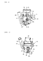
- the cooling water control valve apparatus 10 is provided with a casing 20 which is attached to sections of the opening portions of the water jackets 1a, 1b.
- the casing 20 is provided with a flange portion 21 including a first inlet port 22 which is communicated with the opening portion of the water jacket 1a and a second inlet port 22a which is communicated with the opening portion of the water jacket 1b.
- the casing 20 is provided with a first passage portion 23 which includes an inner space communicated with the first inlet port 22 of the flange portion 21 and in which the electronic control valve (a rotary-type valve) 11 having a rotor 12 is arranged, a drive chamber portion 24 in which a motor 81 as drive means to rotatively drive the rotor 12 is arranged, a second passage portion 25 in which a thermosensitive valve 40 is arranged and which is communicated with the second inlet port 22a of the flange portion 21, a main outlet portion 26 which is communicated with the first passage portion 23 and the second passage portion 25 as being connected to the circulation flow passage 4, a bypass outlet portion 27 which is connected to the bypass flow passage 5 in a state of being branched from the first passage portion 23, and subsidiary outlet portions 28, 28a which are connected to the subsidiary flow passages 6a, 7a.
- a first passage portion 23 which includes an inner space communicated with the first inlet port 22 of the flange portion 21 and in which the electronic control valve (a rotary-type
- a groove in which a seal member is arranged is formed around the first inlet port 22 and the second inlet port 22a.
- the first passage portion 23 which is communicated with the water jacket 1a at the cylinder head side via the first inlet port 22 is connected to the main outlet portion 26 and the subsidiary outlet portions 28, 28a so that cooling water outflowing from the water jacket 1a reaches the main outlet portion 26 and the subsidiary outlet portions 28, 28a as passing through the electronic control valve 11.
- the bypass outlet portion 27 is arranged at a section of the first passage portion 23 at the first inlet port 22 side from the electronic control valve 22. Accordingly, cooling water in the water jacket 1a at the cylinder head side is discharged from the bypass outlet portion 27 to the bypass flow passage 5 with operation of the water pump 2 regardless of opening and closing of the electronic control valve 11.
- the electronic control valve 11 is capable of varying flow rates of cooling water passing through the circulation flow passage 4 and the subsidiary flow passages 6a, 7a from the water jacket 1a at the cylinder head side (capable of opening and closing) in accordance with a rotation angle of the rotor 12. With the rotation angle, the rotor 12 is capable of opening and closing the subsidiary flow passage 6a for the heater 6 and the subsidiary flow passage 7a for the throttle 7 in a state that the circulation flow passage 4 is closed. Accordingly, the flow rates of cooling water for the subsidiary flow passages 6a, 7a and the like can be varied concurrently with adjustment of the flow rate of cooling water for the circulation flow passage 4.
- the rotor 12 of the present embodiment is arranged so that rotation angles of the rotor 12 with which the subsidiary flow passages 6a, 7a can be varied between being closed and being opened are included in a range of rotation angles thereof with which the circulation flow passage 4 is kept in a closed state.
- the rotor 12 may be provided with an opening portion which is communicated with the circulation flow passage 4 as being elongated in the circumferential direction.
- the rotor 12 may be rotatable to cause a state of having communication of opening portions for the subsidiary flow passages 6a, 7a with the subsidiary flow passages 6a, 7a and a state of without having the communication thereof.
- a plurality of opening portions for the circulation flow passage 4 is arranged at the rotor 12 side by side in the circumferential direction.
- the subsidiary flow passages 6a, 7a can be opened and closed in a state that the circulation flow passage 4 is opened.
- a mechanism to rotate the rotor 12 includes a gear train structured with a gear 63 which is integrally rotated with a rotational shaft 62 of the rotor 12 and an intermediate gear portion 84 which coaxially includes a gear engaged with the gear 63 and a gear engaged with a drive gear (not illustrated) arranged at the motor 81 being a stepping motor.
- the gear train (power transmitting mechanism) transmits a drive force from the motor 81 to the rotor 12.
- first passage portion 23 and the second passage portion 25 are basically partitioned by a partition wall 86. Accordingly, cooling water inflowing from the first inlet port 22 passes through the electronic control valve 11 and cooling water inflowing from the second inlet port 22a passes through the thermosensitive valve 40.
- the thermosensitive valve 40 includes a valve body portion 41 which performs opening and closing between the second inlet port 22a of the second passage portion 25 and the main outlet portion 26, a temperature detecting medium 42 which drives the valve body portion 41 based on temperature variation, and a return spring 43 which urges the valve body portion 41 to the closing side.
- the temperature detecting medium 42 is formed with thermo-wax, for example.
- thermo-wax for example.
- the temperature detecting medium 42 causes the second inlet port 22a and the main outlet portion 26 to be communicated by opening the valve body portion 41 when temperature becomes higher than the set temperature (range) and closes communication between the second inlet port 22a and the main outlet portion 26 by closing the valve body portion 41 when temperature becomes lower than the set temperature (range).
- the temperature detecting medium 42 includes thermo-wax accommodated in a case and a known built-in mechanism to drive the valve body portion 41 in accordance with expansion and contraction of the thermo-wax.
- the return spring 43 urges the valve body portion 41 to the closing side. Accordingly, in a case that the valve body portion 41 is in a state of being free to be opened and closed caused by breakage of the temperature detecting medium 42, for example, the valve body portion 41 is closed.
- the valve body portion 41 is driven against an urging force of the return spring 43 with expansion of the thermo-wax which is accommodated in the case of the temperature detecting medium 42.
- the bypass outlet portion 27 is formed at the casing 20 as being branched from the first passage portion 23.
- a return flow passage 27a is formed at the partition wall 86 which partitions the first passage portion 23 and the second passage portion 25. Accordingly, a part of cooling water flowing from the water jacket 1b toward the second passage portion 25 flows to the bypass outlet portion 27 through the return flow passage 27a and the first passage portion 23. According to the above, in a state that at least the thermosensitive valve 40 is closed, a part of cooling water flowing through the bypass flow passage 5 is cooling water outflowing from the second passage portion 25 having the thermosensitive valve 40, so that cooling water passing around the temperature detecting medium 42 of the thermosensitive valve 40 flows through the bypass flow passage 5.
- the return flow passage 27a is opened at a section of the second passage portion 25 where the temperature detecting medium 42 of the thermosensitive valve 40 is located, so that cooling water from the water jacket 1b flows toward the temperature detecting medium 42 of the second passage portion 25.
- thermosensitive valve 40 in a state that the thermosensitive valve 40 is closed and the electronic control valve 11 is closed as well when the water pump 2 is operated with starting of the engine 1, cooling water in the first passage portion 23 at the first inlet port 22 side being at the upstream side from the electronic control valve 11 is sucked by the water pump 2 through the bypass outlet portion 27 and the bypass flow passage 5. Accordingly, pressure at the first passage portion 23 side becomes lower than that at the second passage portion 25 side, so that cooling water flows through the return flow passage 27a to the first passage portion 23 side from a section of the second passage portion 25 where the temperature detecting medium 42 is located.
- cooling water flows from the second passage portion 25 side to the first passage portion 23 side through the return flow passage 27a. Accordingly, cooling water in the water jacket 1b inflows to the second passage portion 25 through the second inlet port 22a. Further, in a state that the electronic control valve 11 is opened while the thermosensitive valve 40 is closed, the first passage portion 23 side has lower pressure than the second passage portion 25 side. Accordingly, cooling water flows through the return flow passage 27a to the first passage portion 23 side from a section of the second passage portion 25 where the temperature detection medium 42 is located.
- thermosensitive valve 40 even in a case that the thermosensitive valve 40 is closed, temperature of cooling water in the water jacket 1b is promptly transmitted to the temperature detecting medium 42 of the thermosensitive valve 40 owing to cooling water flowing through the bypass flow passage 5. Accordingly, the thermosensitive valve 40 can be operated to the opening side in accordance with temperature increase of cooling water in the water jacket 1b.
- a check valve (one-way valve) 82 is arranged at the partition wall 86 between the first passage portion 23 and the second passage portion 25.
- the check valve 82 causes cooling water to flow from the first passage portion 23 side to the second passage portion 25 side owing to pressure being higher than predetermined opening pressure.
- pressure at the first passage portion 23 side becomes higher than that at the second passage portion 25 side, so that the check valve 82 is opened.
- the subsidiary outlet portions 28, 28a are independently arranged into two lines and an outlet pipe 71 is arranged respectively thereto.
- an outlet pipe for the subsidiary outlet portion 28a is not illustrated.
- cooling water control valve apparatus 10 when cooling water is circulated using the circulation flow passage 4 which is arranged between the radiator 3 and the water jacket 1a at the cylinder head side as well as the water jacket 1b at the cylinder block side, flow rates of cooling water of the water jackets 1a, 1b are controlled at the outlet side by the cooling water control valve apparatus 10.
- a flow rate at the bypass flow passage 5 side is increased and an amount of cooling water to be cooled at the radiator 3 is decreased. Accordingly, temperature of cooling water in the water jackets 1a, 1b is increased.
- the cooling water control valve apparatus 10 is provided with the first passage portion 23 which is communicated with the water jacket 1a at the cylinder head side through the first inlet port 22 and the second passage portion 25 which is communicated with the water jacket 1b at the cylinder block side through the second inlet port 22a.
- the electronic control valve 11 is arranged at the first passage portion 23 and the thermosensitive valve 40 is arranged at the second passage portion 25.
- the flow rate of cooling water can be controlled by determining opening and closing or an opening degree of the electronic control valve 11 based on a control program or control setting. Responsiveness of the electronic control valve 11 against cooling water temperature can be quicker than that of the thermosensitive valve 40.
- temperature of cooling water in the water jacket 1b at the cylinder block side is kept higher compared to the cylinder head side.
- the valve is kept opened after temperature in the water jacket 1b is increased with engine operation. Accordingly, cooling water temperature can be controlled sufficiently with the thermosensitive valve 40. In this case, cost reduction can be achieved compared to a case that electric control valves are used for both of the water jacket 1a at the cylinder head side and the water jacket 1b at the cylinder block side.
- the bypass flow passage 5 is structured to circulate cooling water not of the water jacket 1b at the cylinder block side but of the water jacket 1a at the cylinder head side. That is, the cooling water control valve apparatus 10 is structured to circulate cooling water of the water jacket 1a at the cylinder head side which is required to be set at lower temperature than that at cylinder block side.
- bypass outlet portion 27 as an end portion of the bypass flow passage 5 from which cooling water from the water jacket 1a is discharged is arranged between the electronic control valve 11 and the first inlet port 22 of the first passage portion 23 of the cooling water control valve apparatus 10. Furthermore, the narrow return flow passage 27a which provides communication between the first passage portion 23 and the second passage portion 25 is arranged at the partition wall 86 arranged between the first passage portion 23 and the second passage portion 25. Accordingly, as described above, cooling water flows even when the thermosensitive valve 40 is closed at the second passage portion 25.
- thermosensitive valve 40 can detect temperature of cooling water in the water jacket 1b owing to flow of cooling water. Therefore, the thermosensitive valve 40 is capable of being opened and closed without delay against temperature variation of cooling water in the water jacket 1b.
- the inner diameter of the return flow passage 27a is smaller than the inner diameter of the bypass outlet portion 27.
- the abovementioned check valve 82 is arranged at the partition wall 86 between the first passage portion 23 and the second passage portion 25 to allow flowing of cooling water from the first passage portion 23 to the second passage portion 25 and to prevent flowing in the opposite direction. Accordingly, in a case that the electronic control valve 11 is kept closed as being incapable of being opened in the first passage portion 23 owing to occurrence of a defect of some sort at the electronic control valve 11 (e.g., locking of the rotor 12), the check valve 82 is opened and cooling water flows from the first passage portion 23 to the second passage portion 25.
- cooling water in the water jacket 1a can be cooled as being fed to the radiator 3 through the thermosensitive valve 40.
- the cooling water control valve apparatus 10 can control flow rates of cooling water at more lines.
- the first inlet port 22 is connected to the water jacket 1a at the cylinder head side and the second inlet port 22a is connected to the water jacket 1b at the cylinder block side.
- the first inlet port 22 or the second inlet port 22a may be connected to the separated water jacket.
Landscapes
- Engineering & Computer Science (AREA)
- Chemical & Material Sciences (AREA)
- Combustion & Propulsion (AREA)
- Mechanical Engineering (AREA)
- General Engineering & Computer Science (AREA)
- Physics & Mathematics (AREA)
- General Physics & Mathematics (AREA)
- Automation & Control Theory (AREA)
- Temperature-Responsive Valves (AREA)
- Cylinder Crankcases Of Internal Combustion Engines (AREA)
Applications Claiming Priority (1)
| Application Number | Priority Date | Filing Date | Title |
|---|---|---|---|
| JP2012041525A JP5919031B2 (ja) | 2012-02-28 | 2012-02-28 | 冷却水制御バルブ装置 |
Publications (2)
| Publication Number | Publication Date |
|---|---|
| EP2634388A1 true EP2634388A1 (de) | 2013-09-04 |
| EP2634388B1 EP2634388B1 (de) | 2015-01-28 |
Family
ID=47715881
Family Applications (1)
| Application Number | Title | Priority Date | Filing Date |
|---|---|---|---|
| EP13153978.5A Active EP2634388B1 (de) | 2012-02-28 | 2013-02-05 | Kühlwasser-Steuerventilvorrichtung |
Country Status (4)
| Country | Link |
|---|---|
| US (1) | US9518503B2 (de) |
| EP (1) | EP2634388B1 (de) |
| JP (1) | JP5919031B2 (de) |
| CN (1) | CN103291435B (de) |
Cited By (2)
| Publication number | Priority date | Publication date | Assignee | Title |
|---|---|---|---|---|
| WO2015149764A1 (de) * | 2014-04-04 | 2015-10-08 | Schaeffler Technologies AG & Co. KG | Wärmemanagementmodul kombiniert mit einer thermostatischen regelung |
| WO2020191424A1 (de) | 2019-03-27 | 2020-10-01 | Avl List Gmbh | Brennkraftmaschine |
Families Citing this family (44)
| Publication number | Priority date | Publication date | Assignee | Title |
|---|---|---|---|---|
| JP6050952B2 (ja) * | 2012-05-15 | 2016-12-21 | 株式会社ミクニ | 冷却水制御バルブ装置 |
| KR101500391B1 (ko) | 2013-12-20 | 2015-03-09 | 현대자동차 주식회사 | 멀티 유량 제어밸브를 갖는 엔진 |
| DE102015200052B4 (de) * | 2014-01-16 | 2018-06-07 | Ford Global Technologies, Llc | Flüssigkeitsgekühlte Brennkraftmaschine mit Schaltkulisse und Verfahren zur Steuerung der Schaltkulisse einer derartigen Brennkraftmaschine |
| JP6272094B2 (ja) * | 2014-03-12 | 2018-01-31 | 日立オートモティブシステムズ株式会社 | 内燃機関の冷却装置 |
| JP6266393B2 (ja) * | 2014-03-19 | 2018-01-24 | 日立オートモティブシステムズ株式会社 | 内燃機関の冷却装置 |
| CN106232960B (zh) * | 2014-04-25 | 2018-11-16 | 日立汽车系统株式会社 | 冷却控制装置,流量控制阀以及冷却控制方法 |
| KR101558377B1 (ko) | 2014-06-05 | 2015-10-19 | 현대자동차 주식회사 | 냉각수 제어 밸브를 갖는 엔진 |
| KR101542997B1 (ko) | 2014-07-02 | 2015-08-07 | 현대자동차 주식회사 | 엔진의 냉각수 제어밸브 |
| KR101575338B1 (ko) * | 2014-07-08 | 2015-12-07 | 현대자동차 주식회사 | 엔진의 냉각수 제어밸브 |
| JP6319018B2 (ja) * | 2014-09-25 | 2018-05-09 | マツダ株式会社 | エンジンの冷却システム |
| KR101619278B1 (ko) | 2014-10-29 | 2016-05-10 | 현대자동차 주식회사 | 냉각수 제어밸브를 갖는 엔진시스템 |
| CN104533593B (zh) * | 2014-11-04 | 2017-02-15 | 江苏康沃动力科技股份有限公司 | 一种柴油机冷却循环系统及方法 |
| JP6380073B2 (ja) * | 2014-12-12 | 2018-08-29 | アイシン精機株式会社 | 冷媒制御バルブ装置 |
| JP6350255B2 (ja) * | 2014-12-12 | 2018-07-04 | アイシン精機株式会社 | 冷媒制御バルブ装置 |
| DE102015201366A1 (de) * | 2015-01-27 | 2016-07-28 | Mahle International Gmbh | Ventileinrichtung, insbesondere zum Einstellen eines Kühlmittelstroms in einem Kühlsystem für eine Brennkraftmaschine eines Kraftfahrzeugs |
| JP6386411B2 (ja) * | 2015-04-03 | 2018-09-05 | 日立オートモティブシステムズ株式会社 | 内燃機関の冷却システム及びその制御方法 |
| JP6330768B2 (ja) * | 2015-09-16 | 2018-05-30 | トヨタ自動車株式会社 | エンジン冷却装置 |
| KR101683530B1 (ko) * | 2015-11-18 | 2016-12-07 | 현대자동차 주식회사 | 냉각수 제어밸브를 갖는 엔진시스템 |
| JP2017096152A (ja) * | 2015-11-24 | 2017-06-01 | アイシン精機株式会社 | 内燃機関の冷却システム |
| CN105422247B (zh) * | 2015-12-21 | 2017-11-14 | 浙江大学 | 一种基于分体冷却及反向冷却的发动机智能冷却系统及控制方法 |
| JP6572805B2 (ja) * | 2016-03-10 | 2019-09-11 | スズキ株式会社 | エンジンのオイル通路構造 |
| KR101720568B1 (ko) * | 2016-05-04 | 2017-03-29 | 엔브이에이치코리아(주) | 통합 유량 제어밸브 |
| JP6446420B2 (ja) * | 2016-09-29 | 2018-12-26 | 本田技研工業株式会社 | 水冷エンジン搭載鞍乗り型車両 |
| WO2018104106A1 (en) * | 2016-12-09 | 2018-06-14 | Volvo Truck Corporation | A cooling system valve |
| JP6911363B2 (ja) | 2017-02-13 | 2021-07-28 | スズキ株式会社 | 内燃機関の冷却装置 |
| DE102017119921A1 (de) * | 2017-02-17 | 2018-08-23 | Borgwarner Ludwigsburg Gmbh | Steuervorrichtung für ein Fluid |
| US11285778B2 (en) * | 2017-06-14 | 2022-03-29 | Denso Corporation | Valve device |
| JP7114890B2 (ja) * | 2017-12-12 | 2022-08-09 | 株式会社デンソー | 冷却水制御弁装置 |
| CN110741192B (zh) | 2017-06-14 | 2022-03-22 | 株式会社电装 | 阀装置 |
| JP7114889B2 (ja) * | 2017-12-12 | 2022-08-09 | 株式会社デンソー | 冷却水制御弁装置、および、それを用いたエンジン冷却システム |
| US10132228B1 (en) * | 2017-08-25 | 2018-11-20 | Hyundai Motor Company | Cooling system for an engine |
| FR3070432B1 (fr) * | 2017-08-30 | 2019-08-16 | Psa Automobiles Sa | Ensemble d’un circuit de refroidissement pour un moteur thermique et une boite de vitesses |
| KR102359941B1 (ko) | 2017-09-21 | 2022-02-07 | 현대자동차 주식회사 | 엔진 냉각 시스템 |
| KR102371256B1 (ko) * | 2017-10-24 | 2022-03-04 | 현대자동차 주식회사 | 냉각수 제어 밸브유닛, 및 이를 구비한 냉각시스템 |
| KR102463203B1 (ko) * | 2017-11-29 | 2022-11-03 | 현대자동차 주식회사 | 냉각수 제어 밸브유닛, 및 이를 구비한 엔진 냉각 시스템 |
| KR102496255B1 (ko) * | 2017-12-11 | 2023-02-08 | 현대자동차주식회사 | 유량제어밸브 |
| CN109944675B (zh) * | 2017-12-20 | 2020-05-12 | 广州汽车集团股份有限公司 | 一种发动机的冷却装置 |
| KR102496807B1 (ko) * | 2018-08-03 | 2023-02-06 | 현대자동차 주식회사 | 냉각수 유량 제어 시스템 및 그 제어방법 |
| KR20200059956A (ko) * | 2018-11-22 | 2020-05-29 | 현대자동차주식회사 | 엔진의 워터자켓 및 이를 포함한 엔진 냉각시스템 |
| US11098638B2 (en) | 2018-11-30 | 2021-08-24 | Progress Rail Locomotive Inc. | Engine jacket cooling system for locomotive |
| KR20200112150A (ko) * | 2019-03-21 | 2020-10-05 | 현대자동차주식회사 | 통합유량제어밸브 및 통합유량제어밸브를 갖는 엔진 냉각 시스템 |
| KR20210099333A (ko) * | 2020-02-04 | 2021-08-12 | 현대자동차주식회사 | 엔진 제어 장치 및 그 방법 |
| CN113062793B (zh) * | 2021-03-31 | 2022-06-03 | 贵州电子科技职业学院 | 一种汽车散热器回水管路结构 |
| JP2022175443A (ja) * | 2021-05-13 | 2022-11-25 | マツダ株式会社 | エンジンの冷却システム |
Citations (6)
| Publication number | Priority date | Publication date | Assignee | Title |
|---|---|---|---|---|
| US3776457A (en) * | 1971-10-01 | 1973-12-04 | P Cardi | Fail-safe device for thermostatic valves |
| US4186872A (en) * | 1976-04-22 | 1980-02-05 | Bland William M Jr | Alternate path cooling system for liquid cooled devices such as engines |
| WO2008029029A1 (fr) * | 2006-09-06 | 2008-03-13 | Peugeot Citroen Automobiles Sa | Dispositif de distribution de liquide de refroidissement dans un moteur de vehicule automobile |
| US20080168956A1 (en) * | 2007-01-17 | 2008-07-17 | Martin Lutz | Integrated Engine Thermal Management |
| WO2008145461A1 (fr) * | 2007-05-25 | 2008-12-04 | Valeo Systemes Thermiques | Module pour un circuit de refroidissement d'un moteur de vehicule automobile |
| US20080308049A1 (en) * | 2006-05-26 | 2008-12-18 | Mark Iv Systemes Moteurs (Sas) | Cooling circuit for an internal combustion engine |
Family Cites Families (14)
| Publication number | Priority date | Publication date | Assignee | Title |
|---|---|---|---|---|
| JPS5793620A (en) * | 1980-12-02 | 1982-06-10 | Toyota Motor Corp | Cooler for engine |
| KR920006509Y1 (ko) * | 1985-10-09 | 1992-09-19 | 마쯔다 가부시기가이샤 | 엔진의 냉각구조 |
| JPH0768897B2 (ja) * | 1988-04-04 | 1995-07-26 | マツダ株式会社 | エンジンの冷却装置 |
| US5279265A (en) * | 1991-07-26 | 1994-01-18 | Nissan Motor Co., Ltd. | V-type internal combustion engine with improved water pump arrangement |
| DE19932313A1 (de) * | 1999-07-10 | 2001-01-18 | Daimler Chrysler Ag | Steuervorrichtung für den Kühl- und Heizungskreislauf einer Brennkraftmaschine |
| US6343573B1 (en) * | 2000-08-22 | 2002-02-05 | Nippon Thermostat Co., Ltd. | Thermostat device |
| JP2002227648A (ja) * | 2001-01-30 | 2002-08-14 | Aisin Seiki Co Ltd | エンジンの冷却装置 |
| KR100482428B1 (ko) * | 2001-10-26 | 2005-04-14 | 현대자동차주식회사 | 2개의 서모스텟을 이용한 엔진 냉각 시스템 |
| US6539899B1 (en) * | 2002-02-11 | 2003-04-01 | Visteon Global Technologies, Inc. | Rotary valve for single-point coolant diversion in engine cooling system |
| JP4239623B2 (ja) * | 2003-03-12 | 2009-03-18 | マツダ株式会社 | エンジンの冷却装置 |
| FR2893113B1 (fr) * | 2005-11-04 | 2009-03-06 | Valeo Systemes Thermiques | Vanne de commande a etancheite amelioree pour circuit de circulation de fluide |
| JP4432898B2 (ja) * | 2005-12-20 | 2010-03-17 | トヨタ自動車株式会社 | 内燃機関の冷却装置 |
| JP2009293575A (ja) * | 2008-06-09 | 2009-12-17 | Nissan Motor Co Ltd | 内燃機関のオイル通路構造およびシリンダヘッド |
| DE102009009854B4 (de) * | 2009-02-20 | 2012-05-24 | Audi Ag | Kühlmittelkreislauf für eine Brennkraftmaschine |
-
2012
- 2012-02-28 JP JP2012041525A patent/JP5919031B2/ja active Active
-
2013
- 2013-02-05 EP EP13153978.5A patent/EP2634388B1/de active Active
- 2013-02-22 US US13/774,040 patent/US9518503B2/en active Active
- 2013-02-27 CN CN201310061117.6A patent/CN103291435B/zh active Active
Patent Citations (7)
| Publication number | Priority date | Publication date | Assignee | Title |
|---|---|---|---|---|
| US3776457A (en) * | 1971-10-01 | 1973-12-04 | P Cardi | Fail-safe device for thermostatic valves |
| US4186872A (en) * | 1976-04-22 | 1980-02-05 | Bland William M Jr | Alternate path cooling system for liquid cooled devices such as engines |
| US20080308049A1 (en) * | 2006-05-26 | 2008-12-18 | Mark Iv Systemes Moteurs (Sas) | Cooling circuit for an internal combustion engine |
| WO2008029029A1 (fr) * | 2006-09-06 | 2008-03-13 | Peugeot Citroen Automobiles Sa | Dispositif de distribution de liquide de refroidissement dans un moteur de vehicule automobile |
| US20080168956A1 (en) * | 2007-01-17 | 2008-07-17 | Martin Lutz | Integrated Engine Thermal Management |
| WO2008145461A1 (fr) * | 2007-05-25 | 2008-12-04 | Valeo Systemes Thermiques | Module pour un circuit de refroidissement d'un moteur de vehicule automobile |
| JP2010528229A (ja) | 2007-05-25 | 2010-08-19 | ヴァレオ システム テルミク | 自動車エンジンの冷却回路用のモジュール |
Cited By (4)
| Publication number | Priority date | Publication date | Assignee | Title |
|---|---|---|---|---|
| WO2015149764A1 (de) * | 2014-04-04 | 2015-10-08 | Schaeffler Technologies AG & Co. KG | Wärmemanagementmodul kombiniert mit einer thermostatischen regelung |
| WO2020191424A1 (de) | 2019-03-27 | 2020-10-01 | Avl List Gmbh | Brennkraftmaschine |
| AT522272A1 (de) * | 2019-03-27 | 2020-10-15 | Avl List Gmbh | Brennkraftmaschine |
| AT522272B1 (de) * | 2019-03-27 | 2021-03-15 | Avl List Gmbh | Brennkraftmaschine |
Also Published As
| Publication number | Publication date |
|---|---|
| US9518503B2 (en) | 2016-12-13 |
| US20130221116A1 (en) | 2013-08-29 |
| CN103291435A (zh) | 2013-09-11 |
| JP5919031B2 (ja) | 2016-05-18 |
| EP2634388B1 (de) | 2015-01-28 |
| CN103291435B (zh) | 2018-03-23 |
| JP2013177843A (ja) | 2013-09-09 |
Similar Documents
| Publication | Publication Date | Title |
|---|---|---|
| EP2634388B1 (de) | Kühlwasser-Steuerventilvorrichtung | |
| JP6846083B2 (ja) | 弁及び冷却水の循環システム | |
| US10287968B2 (en) | Engine cooling system | |
| JP6135684B2 (ja) | エンジンの冷却装置 | |
| KR102496255B1 (ko) | 유량제어밸브 | |
| US8881693B2 (en) | Cooling system of engine | |
| EP2743474A1 (de) | Vorrichtung zur steuerung eines kühlmittelventils | |
| WO2015163181A1 (ja) | 冷却制御装置、流量制御弁及び冷却制御方法 | |
| US9752493B2 (en) | Valve with integrated wax motor bypass fail safe | |
| KR20170044725A (ko) | 내연기관 | |
| KR20050084274A (ko) | 엔진 냉각 시스템에서 유속에 대한 열적제어 | |
| JP6013022B2 (ja) | 内燃機関の冷却制御装置及びその冷却制御方法 | |
| US10900408B2 (en) | Cooling water control valve device | |
| JP2007291928A (ja) | エンジンの冷却装置 | |
| WO2019176261A1 (ja) | 流路切換弁及び自動車用熱媒体システム | |
| JP4983560B2 (ja) | エンジンの冷却装置 | |
| US20100276613A1 (en) | Thermostatic device and related method | |
| JP2017155672A (ja) | 車両の液体循環システム | |
| JP6135685B2 (ja) | エンジンの冷却装置 | |
| KR102075137B1 (ko) | 차량용 냉각시스템 제어방법 | |
| JP7488134B2 (ja) | 冷却システム | |
| JP2016151215A (ja) | 内燃機関の冷却装置 | |
| JP2007291927A (ja) | エンジンの冷却装置 | |
| CN115306533A (zh) | 流量调节装置、发动机的扭矩调节方法及车辆 | |
| GB2587384A (en) | Flow control devices for engine cooling systems |
Legal Events
| Date | Code | Title | Description |
|---|---|---|---|
| PUAI | Public reference made under article 153(3) epc to a published international application that has entered the european phase |
Free format text: ORIGINAL CODE: 0009012 |
|
| AK | Designated contracting states |
Kind code of ref document: A1 Designated state(s): AL AT BE BG CH CY CZ DE DK EE ES FI FR GB GR HR HU IE IS IT LI LT LU LV MC MK MT NL NO PL PT RO RS SE SI SK SM TR |
|
| AX | Request for extension of the european patent |
Extension state: BA ME |
|
| 17P | Request for examination filed |
Effective date: 20140303 |
|
| RBV | Designated contracting states (corrected) |
Designated state(s): AL AT BE BG CH CY CZ DE DK EE ES FI FR GB GR HR HU IE IS IT LI LT LU LV MC MK MT NL NO PL PT RO RS SE SI SK SM TR |
|
| GRAP | Despatch of communication of intention to grant a patent |
Free format text: ORIGINAL CODE: EPIDOSNIGR1 |
|
| INTG | Intention to grant announced |
Effective date: 20140819 |
|
| GRAS | Grant fee paid |
Free format text: ORIGINAL CODE: EPIDOSNIGR3 |
|
| GRAA | (expected) grant |
Free format text: ORIGINAL CODE: 0009210 |
|
| AK | Designated contracting states |
Kind code of ref document: B1 Designated state(s): AL AT BE BG CH CY CZ DE DK EE ES FI FR GB GR HR HU IE IS IT LI LT LU LV MC MK MT NL NO PL PT RO RS SE SI SK SM TR |
|
| REG | Reference to a national code |
Ref country code: GB Ref legal event code: FG4D |
|
| REG | Reference to a national code |
Ref country code: CH Ref legal event code: EP |
|
| REG | Reference to a national code |
Ref country code: IE Ref legal event code: FG4D |
|
| REG | Reference to a national code |
Ref country code: DE Ref legal event code: R096 Ref document number: 602013000901 Country of ref document: DE Effective date: 20150312 |
|
| REG | Reference to a national code |
Ref country code: AT Ref legal event code: REF Ref document number: 708346 Country of ref document: AT Kind code of ref document: T Effective date: 20150315 |
|
| REG | Reference to a national code |
Ref country code: AT Ref legal event code: MK05 Ref document number: 708346 Country of ref document: AT Kind code of ref document: T Effective date: 20150128 |
|
| REG | Reference to a national code |
Ref country code: NL Ref legal event code: VDEP Effective date: 20150128 |
|
| REG | Reference to a national code |
Ref country code: LT Ref legal event code: MG4D |
|
| PG25 | Lapsed in a contracting state [announced via postgrant information from national office to epo] |
Ref country code: BE Free format text: LAPSE BECAUSE OF NON-PAYMENT OF DUE FEES Effective date: 20150228 |
|
| PG25 | Lapsed in a contracting state [announced via postgrant information from national office to epo] |
Ref country code: FI Free format text: LAPSE BECAUSE OF FAILURE TO SUBMIT A TRANSLATION OF THE DESCRIPTION OR TO PAY THE FEE WITHIN THE PRESCRIBED TIME-LIMIT Effective date: 20150128 Ref country code: NO Free format text: LAPSE BECAUSE OF FAILURE TO SUBMIT A TRANSLATION OF THE DESCRIPTION OR TO PAY THE FEE WITHIN THE PRESCRIBED TIME-LIMIT Effective date: 20150428 Ref country code: BG Free format text: LAPSE BECAUSE OF FAILURE TO SUBMIT A TRANSLATION OF THE DESCRIPTION OR TO PAY THE FEE WITHIN THE PRESCRIBED TIME-LIMIT Effective date: 20150428 Ref country code: HR Free format text: LAPSE BECAUSE OF FAILURE TO SUBMIT A TRANSLATION OF THE DESCRIPTION OR TO PAY THE FEE WITHIN THE PRESCRIBED TIME-LIMIT Effective date: 20150128 Ref country code: SE Free format text: LAPSE BECAUSE OF FAILURE TO SUBMIT A TRANSLATION OF THE DESCRIPTION OR TO PAY THE FEE WITHIN THE PRESCRIBED TIME-LIMIT Effective date: 20150128 Ref country code: ES Free format text: LAPSE BECAUSE OF FAILURE TO SUBMIT A TRANSLATION OF THE DESCRIPTION OR TO PAY THE FEE WITHIN THE PRESCRIBED TIME-LIMIT Effective date: 20150128 Ref country code: LT Free format text: LAPSE BECAUSE OF FAILURE TO SUBMIT A TRANSLATION OF THE DESCRIPTION OR TO PAY THE FEE WITHIN THE PRESCRIBED TIME-LIMIT Effective date: 20150128 |
|
| PG25 | Lapsed in a contracting state [announced via postgrant information from national office to epo] |
Ref country code: AT Free format text: LAPSE BECAUSE OF FAILURE TO SUBMIT A TRANSLATION OF THE DESCRIPTION OR TO PAY THE FEE WITHIN THE PRESCRIBED TIME-LIMIT Effective date: 20150128 Ref country code: NL Free format text: LAPSE BECAUSE OF FAILURE TO SUBMIT A TRANSLATION OF THE DESCRIPTION OR TO PAY THE FEE WITHIN THE PRESCRIBED TIME-LIMIT Effective date: 20150128 Ref country code: IS Free format text: LAPSE BECAUSE OF FAILURE TO SUBMIT A TRANSLATION OF THE DESCRIPTION OR TO PAY THE FEE WITHIN THE PRESCRIBED TIME-LIMIT Effective date: 20150528 Ref country code: PL Free format text: LAPSE BECAUSE OF FAILURE TO SUBMIT A TRANSLATION OF THE DESCRIPTION OR TO PAY THE FEE WITHIN THE PRESCRIBED TIME-LIMIT Effective date: 20150128 Ref country code: LV Free format text: LAPSE BECAUSE OF FAILURE TO SUBMIT A TRANSLATION OF THE DESCRIPTION OR TO PAY THE FEE WITHIN THE PRESCRIBED TIME-LIMIT Effective date: 20150128 Ref country code: GR Free format text: LAPSE BECAUSE OF FAILURE TO SUBMIT A TRANSLATION OF THE DESCRIPTION OR TO PAY THE FEE WITHIN THE PRESCRIBED TIME-LIMIT Effective date: 20150429 Ref country code: RS Free format text: LAPSE BECAUSE OF FAILURE TO SUBMIT A TRANSLATION OF THE DESCRIPTION OR TO PAY THE FEE WITHIN THE PRESCRIBED TIME-LIMIT Effective date: 20150128 |
|
| REG | Reference to a national code |
Ref country code: DE Ref legal event code: R097 Ref document number: 602013000901 Country of ref document: DE |
|
| PG25 | Lapsed in a contracting state [announced via postgrant information from national office to epo] |
Ref country code: SK Free format text: LAPSE BECAUSE OF FAILURE TO SUBMIT A TRANSLATION OF THE DESCRIPTION OR TO PAY THE FEE WITHIN THE PRESCRIBED TIME-LIMIT Effective date: 20150128 Ref country code: DK Free format text: LAPSE BECAUSE OF FAILURE TO SUBMIT A TRANSLATION OF THE DESCRIPTION OR TO PAY THE FEE WITHIN THE PRESCRIBED TIME-LIMIT Effective date: 20150128 Ref country code: CZ Free format text: LAPSE BECAUSE OF FAILURE TO SUBMIT A TRANSLATION OF THE DESCRIPTION OR TO PAY THE FEE WITHIN THE PRESCRIBED TIME-LIMIT Effective date: 20150128 Ref country code: MC Free format text: LAPSE BECAUSE OF FAILURE TO SUBMIT A TRANSLATION OF THE DESCRIPTION OR TO PAY THE FEE WITHIN THE PRESCRIBED TIME-LIMIT Effective date: 20150128 Ref country code: RO Free format text: LAPSE BECAUSE OF FAILURE TO SUBMIT A TRANSLATION OF THE DESCRIPTION OR TO PAY THE FEE WITHIN THE PRESCRIBED TIME-LIMIT Effective date: 20150128 Ref country code: EE Free format text: LAPSE BECAUSE OF FAILURE TO SUBMIT A TRANSLATION OF THE DESCRIPTION OR TO PAY THE FEE WITHIN THE PRESCRIBED TIME-LIMIT Effective date: 20150128 |
|
| REG | Reference to a national code |
Ref country code: IE Ref legal event code: MM4A |
|
| PLBE | No opposition filed within time limit |
Free format text: ORIGINAL CODE: 0009261 |
|
| STAA | Information on the status of an ep patent application or granted ep patent |
Free format text: STATUS: NO OPPOSITION FILED WITHIN TIME LIMIT |
|
| 26N | No opposition filed |
Effective date: 20151029 |
|
| REG | Reference to a national code |
Ref country code: FR Ref legal event code: PLFP Year of fee payment: 4 |
|
| PG25 | Lapsed in a contracting state [announced via postgrant information from national office to epo] |
Ref country code: IE Free format text: LAPSE BECAUSE OF NON-PAYMENT OF DUE FEES Effective date: 20150205 |
|
| PG25 | Lapsed in a contracting state [announced via postgrant information from national office to epo] |
Ref country code: SI Free format text: LAPSE BECAUSE OF FAILURE TO SUBMIT A TRANSLATION OF THE DESCRIPTION OR TO PAY THE FEE WITHIN THE PRESCRIBED TIME-LIMIT Effective date: 20150128 |
|
| PG25 | Lapsed in a contracting state [announced via postgrant information from national office to epo] |
Ref country code: BE Free format text: LAPSE BECAUSE OF FAILURE TO SUBMIT A TRANSLATION OF THE DESCRIPTION OR TO PAY THE FEE WITHIN THE PRESCRIBED TIME-LIMIT Effective date: 20150128 |
|
| REG | Reference to a national code |
Ref country code: CH Ref legal event code: PL |
|
| PG25 | Lapsed in a contracting state [announced via postgrant information from national office to epo] |
Ref country code: CH Free format text: LAPSE BECAUSE OF NON-PAYMENT OF DUE FEES Effective date: 20160229 Ref country code: LI Free format text: LAPSE BECAUSE OF NON-PAYMENT OF DUE FEES Effective date: 20160229 |
|
| PG25 | Lapsed in a contracting state [announced via postgrant information from national office to epo] |
Ref country code: MT Free format text: LAPSE BECAUSE OF FAILURE TO SUBMIT A TRANSLATION OF THE DESCRIPTION OR TO PAY THE FEE WITHIN THE PRESCRIBED TIME-LIMIT Effective date: 20150128 |
|
| REG | Reference to a national code |
Ref country code: FR Ref legal event code: PLFP Year of fee payment: 5 |
|
| PG25 | Lapsed in a contracting state [announced via postgrant information from national office to epo] |
Ref country code: HU Free format text: LAPSE BECAUSE OF FAILURE TO SUBMIT A TRANSLATION OF THE DESCRIPTION OR TO PAY THE FEE WITHIN THE PRESCRIBED TIME-LIMIT; INVALID AB INITIO Effective date: 20130205 |
|
| PG25 | Lapsed in a contracting state [announced via postgrant information from national office to epo] |
Ref country code: CY Free format text: LAPSE BECAUSE OF FAILURE TO SUBMIT A TRANSLATION OF THE DESCRIPTION OR TO PAY THE FEE WITHIN THE PRESCRIBED TIME-LIMIT Effective date: 20150128 |
|
| PG25 | Lapsed in a contracting state [announced via postgrant information from national office to epo] |
Ref country code: TR Free format text: LAPSE BECAUSE OF FAILURE TO SUBMIT A TRANSLATION OF THE DESCRIPTION OR TO PAY THE FEE WITHIN THE PRESCRIBED TIME-LIMIT Effective date: 20150128 |
|
| PG25 | Lapsed in a contracting state [announced via postgrant information from national office to epo] |
Ref country code: LU Free format text: LAPSE BECAUSE OF NON-PAYMENT OF DUE FEES Effective date: 20150205 |
|
| REG | Reference to a national code |
Ref country code: FR Ref legal event code: PLFP Year of fee payment: 6 |
|
| PG25 | Lapsed in a contracting state [announced via postgrant information from national office to epo] |
Ref country code: SM Free format text: LAPSE BECAUSE OF FAILURE TO SUBMIT A TRANSLATION OF THE DESCRIPTION OR TO PAY THE FEE WITHIN THE PRESCRIBED TIME-LIMIT Effective date: 20150128 |
|
| PG25 | Lapsed in a contracting state [announced via postgrant information from national office to epo] |
Ref country code: MK Free format text: LAPSE BECAUSE OF FAILURE TO SUBMIT A TRANSLATION OF THE DESCRIPTION OR TO PAY THE FEE WITHIN THE PRESCRIBED TIME-LIMIT Effective date: 20150128 Ref country code: PT Free format text: LAPSE BECAUSE OF FAILURE TO SUBMIT A TRANSLATION OF THE DESCRIPTION OR TO PAY THE FEE WITHIN THE PRESCRIBED TIME-LIMIT Effective date: 20150128 |
|
| PG25 | Lapsed in a contracting state [announced via postgrant information from national office to epo] |
Ref country code: AL Free format text: LAPSE BECAUSE OF FAILURE TO SUBMIT A TRANSLATION OF THE DESCRIPTION OR TO PAY THE FEE WITHIN THE PRESCRIBED TIME-LIMIT Effective date: 20150128 |
|
| PGFP | Annual fee paid to national office [announced via postgrant information from national office to epo] |
Ref country code: IT Payment date: 20181018 Year of fee payment: 13 |
|
| GBPC | Gb: european patent ceased through non-payment of renewal fee |
Effective date: 20200205 |
|
| PG25 | Lapsed in a contracting state [announced via postgrant information from national office to epo] |
Ref country code: GB Free format text: LAPSE BECAUSE OF NON-PAYMENT OF DUE FEES Effective date: 20200205 |
|
| PG25 | Lapsed in a contracting state [announced via postgrant information from national office to epo] |
Ref country code: IT Free format text: LAPSE BECAUSE OF NON-PAYMENT OF DUE FEES Effective date: 20200205 |
|
| PGFP | Annual fee paid to national office [announced via postgrant information from national office to epo] |
Ref country code: DE Payment date: 20231228 Year of fee payment: 12 |
|
| PGFP | Annual fee paid to national office [announced via postgrant information from national office to epo] |
Ref country code: FR Payment date: 20240103 Year of fee payment: 12 |