EP2632838B1 - Drucker mit druckkopfanordnung, kupplungsanordnung und druckbandtransportanordnung - Google Patents
Drucker mit druckkopfanordnung, kupplungsanordnung und druckbandtransportanordnung Download PDFInfo
- Publication number
- EP2632838B1 EP2632838B1 EP11788260.5A EP11788260A EP2632838B1 EP 2632838 B1 EP2632838 B1 EP 2632838B1 EP 11788260 A EP11788260 A EP 11788260A EP 2632838 B1 EP2632838 B1 EP 2632838B1
- Authority
- EP
- European Patent Office
- Prior art keywords
- biasing
- printhead
- assembly
- ribbon
- ramp
- Prior art date
- Legal status (The legal status is an assumption and is not a legal conclusion. Google has not performed a legal analysis and makes no representation as to the accuracy of the status listed.)
- Active
Links
Images






Classifications
-
- B—PERFORMING OPERATIONS; TRANSPORTING
- B41—PRINTING; LINING MACHINES; TYPEWRITERS; STAMPS
- B41J—TYPEWRITERS; SELECTIVE PRINTING MECHANISMS, i.e. MECHANISMS PRINTING OTHERWISE THAN FROM A FORME; CORRECTION OF TYPOGRAPHICAL ERRORS
- B41J23/00—Power drives for actions or mechanisms
- B41J23/02—Mechanical power drives
- B41J23/04—Mechanical power drives with driven mechanism arranged to be clutched to continuously- operating power source
-
- B—PERFORMING OPERATIONS; TRANSPORTING
- B41—PRINTING; LINING MACHINES; TYPEWRITERS; STAMPS
- B41J—TYPEWRITERS; SELECTIVE PRINTING MECHANISMS, i.e. MECHANISMS PRINTING OTHERWISE THAN FROM A FORME; CORRECTION OF TYPOGRAPHICAL ERRORS
- B41J2/00—Typewriters or selective printing mechanisms characterised by the printing or marking process for which they are designed
- B41J2/005—Typewriters or selective printing mechanisms characterised by the printing or marking process for which they are designed characterised by bringing liquid or particles selectively into contact with a printing material
- B41J2/01—Ink jet
- B41J2/135—Nozzles
- B41J2/14—Structure thereof only for on-demand ink jet heads
-
- B—PERFORMING OPERATIONS; TRANSPORTING
- B41—PRINTING; LINING MACHINES; TYPEWRITERS; STAMPS
- B41J—TYPEWRITERS; SELECTIVE PRINTING MECHANISMS, i.e. MECHANISMS PRINTING OTHERWISE THAN FROM A FORME; CORRECTION OF TYPOGRAPHICAL ERRORS
- B41J2/00—Typewriters or selective printing mechanisms characterised by the printing or marking process for which they are designed
- B41J2/315—Typewriters or selective printing mechanisms characterised by the printing or marking process for which they are designed characterised by selective application of heat to a heat sensitive printing or impression-transfer material
- B41J2/32—Typewriters or selective printing mechanisms characterised by the printing or marking process for which they are designed characterised by selective application of heat to a heat sensitive printing or impression-transfer material using thermal heads
- B41J2/325—Typewriters or selective printing mechanisms characterised by the printing or marking process for which they are designed characterised by selective application of heat to a heat sensitive printing or impression-transfer material using thermal heads by selective transfer of ink from ink carrier, e.g. from ink ribbon or sheet
-
- B—PERFORMING OPERATIONS; TRANSPORTING
- B41—PRINTING; LINING MACHINES; TYPEWRITERS; STAMPS
- B41J—TYPEWRITERS; SELECTIVE PRINTING MECHANISMS, i.e. MECHANISMS PRINTING OTHERWISE THAN FROM A FORME; CORRECTION OF TYPOGRAPHICAL ERRORS
- B41J2/00—Typewriters or selective printing mechanisms characterised by the printing or marking process for which they are designed
- B41J2/315—Typewriters or selective printing mechanisms characterised by the printing or marking process for which they are designed characterised by selective application of heat to a heat sensitive printing or impression-transfer material
- B41J2/32—Typewriters or selective printing mechanisms characterised by the printing or marking process for which they are designed characterised by selective application of heat to a heat sensitive printing or impression-transfer material using thermal heads
- B41J2/335—Structure of thermal heads
- B41J2/3358—Cooling arrangements
-
- B—PERFORMING OPERATIONS; TRANSPORTING
- B41—PRINTING; LINING MACHINES; TYPEWRITERS; STAMPS
- B41J—TYPEWRITERS; SELECTIVE PRINTING MECHANISMS, i.e. MECHANISMS PRINTING OTHERWISE THAN FROM A FORME; CORRECTION OF TYPOGRAPHICAL ERRORS
- B41J25/00—Actions or mechanisms not otherwise provided for
- B41J25/304—Bodily-movable mechanisms for print heads or carriages movable towards or from paper surface
- B41J25/312—Bodily-movable mechanisms for print heads or carriages movable towards or from paper surface with print pressure adjustment mechanisms, e.g. pressure-on-the paper mechanisms
-
- B—PERFORMING OPERATIONS; TRANSPORTING
- B41—PRINTING; LINING MACHINES; TYPEWRITERS; STAMPS
- B41J—TYPEWRITERS; SELECTIVE PRINTING MECHANISMS, i.e. MECHANISMS PRINTING OTHERWISE THAN FROM A FORME; CORRECTION OF TYPOGRAPHICAL ERRORS
- B41J33/00—Apparatus or arrangements for feeding ink ribbons or like character-size impression-transfer material
- B41J33/14—Ribbon-feed devices or mechanisms
-
- F—MECHANICAL ENGINEERING; LIGHTING; HEATING; WEAPONS; BLASTING
- F16—ENGINEERING ELEMENTS AND UNITS; GENERAL MEASURES FOR PRODUCING AND MAINTAINING EFFECTIVE FUNCTIONING OF MACHINES OR INSTALLATIONS; THERMAL INSULATION IN GENERAL
- F16D—COUPLINGS FOR TRANSMITTING ROTATION; CLUTCHES; BRAKES
- F16D13/00—Friction clutches
- F16D13/10—Friction clutches with clutching members co-operating with the periphery of a drum, a wheel-rim, or the like
-
- F—MECHANICAL ENGINEERING; LIGHTING; HEATING; WEAPONS; BLASTING
- F16—ENGINEERING ELEMENTS AND UNITS; GENERAL MEASURES FOR PRODUCING AND MAINTAINING EFFECTIVE FUNCTIONING OF MACHINES OR INSTALLATIONS; THERMAL INSULATION IN GENERAL
- F16D—COUPLINGS FOR TRANSMITTING ROTATION; CLUTCHES; BRAKES
- F16D13/00—Friction clutches
- F16D13/58—Details
-
- F—MECHANICAL ENGINEERING; LIGHTING; HEATING; WEAPONS; BLASTING
- F16—ENGINEERING ELEMENTS AND UNITS; GENERAL MEASURES FOR PRODUCING AND MAINTAINING EFFECTIVE FUNCTIONING OF MACHINES OR INSTALLATIONS; THERMAL INSULATION IN GENERAL
- F16D—COUPLINGS FOR TRANSMITTING ROTATION; CLUTCHES; BRAKES
- F16D21/00—Systems comprising a plurality of actuated clutches
-
- B—PERFORMING OPERATIONS; TRANSPORTING
- B41—PRINTING; LINING MACHINES; TYPEWRITERS; STAMPS
- B41J—TYPEWRITERS; SELECTIVE PRINTING MECHANISMS, i.e. MECHANISMS PRINTING OTHERWISE THAN FROM A FORME; CORRECTION OF TYPOGRAPHICAL ERRORS
- B41J23/00—Power drives for actions or mechanisms
- B41J23/02—Mechanical power drives
- B41J23/04—Mechanical power drives with driven mechanism arranged to be clutched to continuously- operating power source
- B41J23/08—Mechanical power drives with driven mechanism arranged to be clutched to continuously- operating power source by one-revolution or part-revolution clutches
-
- B—PERFORMING OPERATIONS; TRANSPORTING
- B41—PRINTING; LINING MACHINES; TYPEWRITERS; STAMPS
- B41J—TYPEWRITERS; SELECTIVE PRINTING MECHANISMS, i.e. MECHANISMS PRINTING OTHERWISE THAN FROM A FORME; CORRECTION OF TYPOGRAPHICAL ERRORS
- B41J25/00—Actions or mechanisms not otherwise provided for
- B41J25/001—Mechanisms for bodily moving print heads or carriages parallel to the paper surface
-
- B—PERFORMING OPERATIONS; TRANSPORTING
- B41—PRINTING; LINING MACHINES; TYPEWRITERS; STAMPS
- B41J—TYPEWRITERS; SELECTIVE PRINTING MECHANISMS, i.e. MECHANISMS PRINTING OTHERWISE THAN FROM A FORME; CORRECTION OF TYPOGRAPHICAL ERRORS
- B41J25/00—Actions or mechanisms not otherwise provided for
- B41J25/304—Bodily-movable mechanisms for print heads or carriages movable towards or from paper surface
- B41J25/316—Bodily-movable mechanisms for print heads or carriages movable towards or from paper surface with tilting motion mechanisms relative to paper surface
-
- B—PERFORMING OPERATIONS; TRANSPORTING
- B41—PRINTING; LINING MACHINES; TYPEWRITERS; STAMPS
- B41J—TYPEWRITERS; SELECTIVE PRINTING MECHANISMS, i.e. MECHANISMS PRINTING OTHERWISE THAN FROM A FORME; CORRECTION OF TYPOGRAPHICAL ERRORS
- B41J33/00—Apparatus or arrangements for feeding ink ribbons or like character-size impression-transfer material
- B41J33/14—Ribbon-feed devices or mechanisms
- B41J33/52—Braking devices therefor
-
- F—MECHANICAL ENGINEERING; LIGHTING; HEATING; WEAPONS; BLASTING
- F16—ENGINEERING ELEMENTS AND UNITS; GENERAL MEASURES FOR PRODUCING AND MAINTAINING EFFECTIVE FUNCTIONING OF MACHINES OR INSTALLATIONS; THERMAL INSULATION IN GENERAL
- F16D—COUPLINGS FOR TRANSMITTING ROTATION; CLUTCHES; BRAKES
- F16D13/00—Friction clutches
- F16D13/22—Friction clutches with axially-movable clutching members
- F16D13/38—Friction clutches with axially-movable clutching members with flat clutching surfaces, e.g. discs
- F16D13/385—Friction clutches with axially-movable clutching members with flat clutching surfaces, e.g. discs double clutches, i.e. comprising two friction disc mounted on one driven shaft
Definitions
- Applicant has identified a number of deficiencies and problems associated with the manufacture, use, operation, and maintenance of conventional thermal transfer printers. Through applied effort, ingenuity, and innovation, Applicant has solved many of these identified problems by developing a solution that is embodied by the present invention, which is described in detail below.
- An example embodiment of the present invention may include a printhead assembly for use in a printing apparatus.
- the printhead assembly may include a printhead and a printhead support bracket.
- the printhead support bracket may include an opposed ramp surface configured for engagement by a biasing ramp of the printing apparatus and a ribbon peel surface configured to receive a ribbon force.
- the opposed ramp surface may be configured to receive a biasing force from the biasing ramp and the biasing force may at least partially counteract the ribbon force.
- the opposed ramp surface may define an angle of between 10 and 25 degrees relative to the major surface of the printhead support bracket.
- Embodiments of the printing apparatus may also include a printhead biasing assembly including a printhead biasing element configured to bias the biasing ramp into contact with the opposed ramp surface of the printhead support bracket.
- the printhead biasing assembly may also include a guide member configured to guide the biasing ramp on a guide path.
- the guide path may be configured to direct the biasing ramp toward a platen.
- the biasing ramp may include a removable wedge.
- the printhead assembly may further include a heat sink, where the heat sink is coupled between the printhead and the printhead support bracket.
- the biasing assembly may be configured to bias the heat sink into contact with a stop member.
- the stop member may be defined by a base structure.
- the printhead assembly may be a replaceable component of the printing apparatus.
- Embodiments of the present invention may provide a method of aligning a printhead.
- the method may include receiving a ribbon force at a peel surface of a printhead support bracket and generating a biasing force at the printhead support bracket to at least partially counteract the ribbon force.
- the biasing force may be directed by a biasing ramp of a biasing assembly engaging an opposed ramp surface of the printhead support bracket.
- the biasing force may be directed at an angle between 10 and 25 degrees relative to the printhead support bracket.
- the method may also include engaging a stop member with a heat sink coupled to the printhead.
- the method may still further include maintaining a substantially consistent ribbon force with a first clutch mechanism configured to engage a ribbon supply spool and a second clutch mechanism configured to engage a take-up spool.
- the method may also include guiding the biasing ramp on a guide path with a guide member of the biasing assembly.
- the method may include directing the biasing ramp toward a platen with the guide member.
- Example embodiments of the present invention may include a system for printing, including a printing apparatus configured to print on media, a printhead, and a printhead support bracket.
- the printhead support bracket may include an opposed ramp surface configured for engagement by a biasing ramp of the printing apparatus and a ribbon peel surface configured to receive a ribbon force.
- the opposed ramp surface may be configured to receive a biasing force from the biasing ramp, where the biasing force at least partially counteracts the ribbon force.
- the printing apparatus may include a printhead biasing assembly including a biasing element configured to bias the biasing ramp into contact with the opposed ramp surface of the printhead support bracket.
- the printhead biasing assembly may include a guide member configured to guide the biasing ramp on a guide path.
- the guide path may be configured to direct the biasing ramp toward a platen of the printing apparatus.
- the biasing ramp may include a removable wedge.
- Example embodiments of the present invention may include a printer ribbon transport assembly.
- the printer ribbon transport assembly may comprise a take-up spool assembly having a take-up core that is configured to receive a ribbon, and wherein the take-up spool assembly is configurable between an engaged position and a disengaged position.
- the printer ribbon transport assembly may further comprise a drive assembly configured to drive the take-up spool assembly to rotate the take-up core in a first direction when the take-up spool assembly is disposed in the engaged position, and a rotation lock mechanism configured to prevent rotation of the take-up core in a second direction, which is opposite to the first direction, when the take-up spool assembly is disposed in the disengaged position.
- the take-up spool assembly may comprise a take-up clutch assembly configured to bias the take-up core in the first direction.
- the rotation lock mechanism may comprise a ratchet assembly.
- the ratchet assembly may comprise a pawl configured to engage a toothed wheel that is rotationally connected to the take-up spool assembly.
- a spring or other biasing element may be configured to bias the pawl to engage the toothed wheel when the take-up spool assembly is in the disengaged position.
- the rotation lock mechanism may further comprise a lever arm coupled to the pawl and configured to cause the pawl to disengage from the toothed wheel when the take-up spool assembly is in the engaged position.
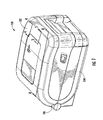
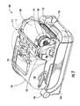
- the printer ribbon transport assembly 112 may be configured to direct a ribbon 114 from the ribbon supply spool 116 over or through a printhead assembly 118 to the ribbon take-up spool 120.
- the ribbon take-up spool 120 may comprise a ribbon take-up core 120A, 120B (see, e.g., FIGS. 7A and 7B ) on which the ribbon 114 is received.
- the ribbon supply clutch assembly 122 and the ribbon take-up clutch assembly 124 may be configured to improve movement of the ribbon 114 and, thus, improve printer performance, as will be described below.
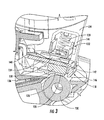
- ink from the ribbon 114 may be transferred onto the print media 108 using a printhead assembly 118. Details concerning a printhead assembly 118 structured in accordance with one embodiment are illustrated in FIG. 3 .
- the depicted printhead assembly 118 may comprise a printhead 126, a platen 130, a printhead biasing assembly 132, and a printhead support bracket 134.
- the printhead 126 may in one embodiment, as further illustrated in FIG. 3A , be configured to heat the ribbon 114 so as to transfer ink from the ribbon to the print media 108.
- the ribbon 114 and print media 108 may travel generally from the left to right and enter a nip 128 formed between the printhead 126 and the platen 130.
- the platen 130 may be driven (i.e., driven to rotate by a motor or other drive means) in some embodiments so as to pull the print media 108 through the nip 128.
- the ribbon take-up spool 120 may also be driven so as to pull the ribbon 114 from the ribbon supply spool 116 through the nip 128 and onto the ribbon take-up spool 120, where the used ribbon is collected.
- the ribbon take-up spool 120 and the ribbon supply spool 116 may each be driven with the ribbon take-up spool 120 having a relatively greater drive force and/or velocity when compared to the ribbon supply spool 116 so as to ensure that appropriate tension is applied to the ribbon.
- the printhead biasing assembly 132 may be configured to bias the printhead 126 into a desired position with respect to the platen 130.
- the depicted printhead biasing assembly 132 comprises a biasing element in the form of a spring 139, a biasing member 140, and a biasing ramp 138 extending from the biasing member 140.
- the depicted biasing ramp 138 defines a wedge that is attached to a biasing member 140.
- the biasing ramp 138 may be integrally formed with the biasing member 140 and, thus, define a single-piece unit.
- the printhead 126 may be supported by a printhead support bracket 134.
- the depicted printhead 126 is configured to attach to the printhead support bracket 134 via a heat sink 136.
- the printhead support bracket 134 defines an opposed ramp 142, which is also generally wedge shaped, that is positioned for engagement by the biasing ramp 138 of the printhead biasing assembly 132.
- the spring 139 of the printhead biasing assembly 132 is configured to bias the biasing ramp 138 into contact with the opposed ramp 142 of the printhead support bracket 134.
- the printhead assembly 118 may further comprise a guide member 144 configured to guide the biasing ramp 138 and the printhead biasing assembly 132 on a guide path.
- the guide member 144 may comprise part of the base structure 104 and/or printer frame structure in some embodiments.
- the guide member 144 is formed as a slot is disposed within a frame member extending from the base structure 104; however, the guide member 144 does not necessarily contact the biasing ramp 138 directly.
- the biasing ramp 138 may be arranged on a carrier, such as biasing member 140, which is guided within the guide member 144. Further, the direction with which the biasing member 140 is biased may be generally in the direction of the platen roller 130 to generate a biasing force of the printhead 126 against the platen roller 130 along nip 128. This biasing force, together with the biasing ramp 138 and the opposed ramp 142 bias the printhead 126 generally toward the platen roller 130 and forward along the media path, toward the bullnose 146.
- the biasing ramp 138 of the printhead biasing assembly 132 may be configured to apply a biasing force to the printhead support bracket 134 through the opposed ramp 142.
- the biasing force in some embodiments, may have at least two components, i.e., a first or downward component that operates to drive the printhead 126 downwardly into the platen 130, and a second or lateral component that operates to drive the printhead support bracket 134 generally forwardly against an applied ribbon force RF, which is illustrated in FIG. 3A .
- the ramp may be a block, wedge, or other complex shape that directs the biasing force in a direction that substantially opposes the applied ribbon force RF.
- This force may tend to pull the ribbon support bracket 134 upwardly and back generally in a direction illustrated by arrow RF in FIG. 3A .
- a ribbon force RF can cause misalignment of the printhead 126 and poor print quality.
- the downwardly biased wedge shape of the biasing ramp 138 tends to drive the printhead support bracket 134 generally forwardly (along the media feed path 150) through engagement with the opposed ramp 142.
- the printhead 126 is maintained in a proper print position despite application of the ribbon force RF to the printhead support bracket 134.
- the biasing ramp 138 of the printhead biasing assembly 132 may be configured to apply a biasing force to the printhead support bracket 134 through the opposed ramp 142 that at least partially counteracts the ribbon force RF applied by the ribbon 114 to the ribbon peel surface 146.
- the biasing force may be directed more towards the platen 130, whereas relatively sharper angles for the biasing ramp angle and the opposed ramp angle (i.e., 30 to 45 degrees) may direct the lateral component of the biasing force to drive the printhead support bracket 134 generally towards the ribbon peel surface 146, substantially along the media feed path 150.
- the biasing ramp 138 and the opposing ramp surface 142 may be located proximate a mid-point of the printhead support bracket along the print line defined between the printhead and the platen roller. Positioning the biasing ramp and opposing ramp surface proximate the mid-point of the printhead support bracket may provide an evenly distributed biasing force against the printhead support bracket along its width. Further, when using center-justified media, positioning the biasing ramp 138 and opposing ramp surface 142 proximate the mid-point may promote an evenly distributed biasing force along the print-line. A further benefit of situating the biasing ramp and the opposing ramp surface proximate the mid-point of the printhead support bracket may be to permit wire-harness connections to the printhead on both ends of the printhead.
- Wire harness connections at both ends of the printhead may allow for the printhead to receive print data from either side, which may be beneficial in resistive printheads where the voltage drop increases along the length of the printhead away from the harness connector.
- Wire harness connections at both ends of a printhead may also be beneficial as any force applied to the printhead via tension of the wire harness may be evenly distributed to both sides of the printhead, thereby better maintaining alignment of the printhead with the platen roller.
- the printhead biasing assembly 132 may be configured to bias a heat sink 136 into contact with a stop member 148 to better align the printhead 126 for printing.
- the stop member 148 may be configured to preclude the floating printhead assembly from advancing any further along the media feed path 150. Contact may be achieved and maintained between the stop member and the printhead assembly in order to maintain a consistent alignment of the printhead relative to the platen.
- the heat sink 136 is coupled to the printhead 126 in order to more efficiently dissipate heat generated at the printhead, thereby cooling the printhead 126 and generally increasing print speed and quality.
- the printhead assembly 118 may be a "floating printhead" assembly having alignment features similar to those disclosed in U.S. Patent No. RE 38,473 , which was reissued on March 23, 2004 and is commonly assigned to the present Applicant, i.e. , ZIH Corp. incorporated by reference in its entirety.
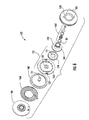
- the ribbon supply clutch assembly 122 and the ribbon take-up clutch assembly 124 each comprise first 150, 1150 and second 158, 1158 spool engagement members, first 152, 1152 and second 160, 1160 friction members, a biasing assembly 162, 1162, a coupler 166, 1166, and a spring 168, 1168 or other biasing element.
- the first spool engagement member 150 of the depicted ribbon supply clutch assembly 122 defines a first friction torque, and defines a first diameter D1.
- the first spool engagement member 150 may be configured to engage a ribbon spool having a diameter that corresponds to the first diameter D1 of the first spool engagement member 150.
- the second spool engagement member 158 of the ribbon supply clutch assembly 122 may define a second friction torque and may define a second diameter D2, where the second friction torque is different than the first friction torque and where the second diameter is different than the first diameter.
- the second spool engagement member 158 may thus be configured to engage a ribbon spool having a diameter that corresponds to the second diameter D2 of the second spool engagement member 158.
- the ribbon supply clutch assembly 122 and the ribbon take-up clutch assembly 124 may each be configured to engage ribbon spools of two differing diameters.
- the friction torque may be impacted by the diameter of the ribbon spool, but may also be impacted by the material and surface finish of the material contained on the ribbon spool. For example, materials with a high coefficient of friction on their surface may require a higher friction torque to dispense material from the spool.
- the depicted first friction member 152 is configured to couple to the second spool engagement member 158 via fasteners 155 (e.g. , flanges or tabs) defined in the coupling plate 156 as shown.
- the depicted second friction member 160 is configured to frictionally engage the first friction member 152, i.e., the coupling plate 156 of the first friction member, to thereby indirectly frictionally engage the second spool engagement member 158 therethrough.
- the above mentioned features may be (though they need not necessarily have to be) common to both the ribbon supply clutch assembly 122 and the ribbon take-up clutch assembly 124 as illustrated in FIGS. 6 and 7 .
- the ribbon supply clutch 122 may function in a slightly different manner than the take-up clutch assembly 124 to better facilitate paying out of the ribbon 114.
- the first friction member 152 may be configured to rotate when the first spool engagement member 150 or the second spool engagement member 158 rotates as ribbon 114 is pulled ( i.e., via the driven take-up spool) from the ribbon supply spool 116.
- the first friction member 152 may rotate via frictional engagement with the first spool engagement member 150.
- the first friction member 152 i.e., the coupling plate 1536 may be configured to rotate when the second spool engagement member 158 rotates via the coupling therebetween.
- the first friction member 152 i.e ., the coupling plate 156) may be configured to rotate the second friction member 160 via frictional engagement therebetween. Accordingly, when the ribbon supply spool 116 imparts rotary motion to either of the first spool engagement member 150 or the second spool engagement member 158, this motion may be transferred to the first friction member 152 and the second friction member 160.
- the ribbon supply clutch assembly 122 may further comprise a coupler 166 configured to couple to the second friction member 160 through a biasing element such as a spring 168.
- the spring 168 may comprise a torsion spring in some embodiments.
- the coupler 166 may be configured to couple to or be supported by a stationary member such as, for example, the base structure 104. Rotation of the second friction member 160 may be configured to rotate the spring 168 via coupling there between, and the spring may be configured to resist movement of the second friction member via the coupling to the stationary member (i.e., the base structure 104) through the coupler 166.
- motion imparted to the first spool engagement member 150 or the second spool engagement member 158 by the ribbon 114 being pulled or drawn from the ribbon supply spool 116 may be subjected to resistance created by frictional engagement between the first friction member 152 and the first spool engagement member 150 and/or frictional engagement between the second spool engagement member 158 and the second friction member 160.
- the spring 168 may operate to gradually increase the resistance force directed counter to the rotation until slippage of the first friction member 152 and/or second friction member 160 occurs. In this way, ribbon may be drawn from supply spool at a smooth and gradually increasing tension rather than at an abrupt, jerky, and inconsistent tension.
- the torsion spring 168 may function to maintain tension across the ribbon web.
- FIG. 7 an embodiment of the ribbon take-up clutch assembly 124 configured to take-up the ribbon 114 with the ribbon take-up spool 120 is illustrated.
- many of the components of the take-up clutch assembly 124 may be similar to those described above with respect to the supply clutch assembly 122, and hence these components will not be discussed in detail.
- the ribbon take-up clutch assembly 124 may further comprise a driven member 170 ( see , e.g. FIG.
- the take-up clutch assembly 124 may be configured to receive rotary motion from the drive assembly 172 through the driven member 170. Accordingly, the coupler 1166 may rotate. Instead of engaging the second friction member 1160 directly, the coupler 1166 may in some embodiments indirectly engage the second friction member 1160.
- the coupler 1166 may engage a spring 1168 that is coupled to the second friction member 1160.
- the spring 1168 may comprise a torsion spring in some embodiments. Thereby, rotation of the coupler 1166 may transfer rotary force to the second friction member 1160 through the spring 1168, which may in turn transfer rotary force to the first friction member 1152 (i.e., the coupling plate 1156).
- the above-described frictional engagements may allow for some slippage within the take-up clutch assembly 124 and further the spring 1168 may create a biasing force that increases when the driven member 170 is driven so as to reduce abrupt changes in force on the ribbon 114 (i.e., to reduce or eliminate spikes or abrupt changes in the tension of the ribbon or the rotational speed supply or take-up cores). Further, the spring 1168 may function to maintain tension on the ribbon 114 when the take-up clutch assembly 124 is not being driven, which can be helpful for preventing previously wound ribbon for backing off its core.
- the second spool engagement member 158, 1158 may define a second diameter D2, D2' that is different from the first diameter D1, D1' of the first spool engagement member 150, 1150.
- the second spool engagement member 158, 1158 defines a second diameter D2, D2' that is larger than the first diameter D1, D1' of the first spool engagement member 150, 1150.
- the second spool engagement member 158, 1158 may be configured to engage a ribbon core approximately of the second diameter D2, D2', and the first spool engagement member 150, 1150 may be configured to engage a ribbon core approximately of the first diameter D1, D1'.
- the ribbon supply clutch assembly 122 and the ribbon take-up clutch assembly 124 may be configured to engage ribbon cores of both the first diameter D1, D1' and the second diameter D2, D2', and hence the printer 100 may be configured to receive different diameters of ribbon cores.
- FIGS. 7A and 7B illustrate the ribbon take-up clutch assembly 124 engaging ribbon take-up cores 120A, 120B on which the ribbon 114 may be collected to form the ribbon take-up spool 120.
- the take-up clutch assembly 124 is depicted engaging a ribbon take-up core 120A with the first spool engagement member 1150.
- the ribbon take-up core 120A may define a diameter DS1 that is substantially the same as the diameter D1' of the first spool engagement member 1150.
- tension in the ribbon 114 may be lost.
- torsion in the spring 1168 of the take-up clutch assembly 124 which biases the ribbon take-up spool 120 in the first direction, may be lost because the driven member 170 of the take-up clutch assembly may no longer be rotationally coupled through the gears to the motor pinion gear 176 of the drive assembly 172.
- the ribbon take-up spool 120, the ribbon supply spool, and the gears configured to engage the ribbon take-up spool drive may be attached to a frame member 105 which is configured to move between an engaged position and a disengaged position.
- the frame member 105 of the illustrated embodiment of FIG. 8 is pivotable about pivot-point 107, in the direction of arrow 103.
- FIG. 8 illustrates the frame member 105 in the engaged position with the driven member 170 of the take-up spool engaged with the drive assembly 172 via a gear train.
- the gear train that engages the driven member 170 of the take-up spool may be disengaged from the drive assembly 172, as illustrated in FIG.
- the drive assembly 172 is disposed on the base member 104 such that upon frame member 105 pivoting along arrow 103, the drive assembly 172 is disengaged from the gear train driving that is engaged with the ribbon take-up spool.
- the frame member 105 may be configured to be biased toward the disengaged position such that upon opening of the lid 102, the frame member 105 moves to the disengaged position.
- the lid 102 may include a latch which secures the lid 102 in the closed position relative to the base 104 such that the frame member 105 becomes secured in the engaged position when the lid 102 is closed.
- the take-up spool assembly 174 may be moved to the disengaged position as the gears of the take-up spool assembly 174 disengage from the gears of the drive assembly 172.
- a spring 186 may be configured to bias the pawl 180 to engage the toothed wheel 182 when the take-up spool assembly 174 is in the disengaged position.
- the rotation lock mechanism 178 may further comprise a lever arm 188 coupled to the pawl 180 and configured to cause the pawl to disengage from the toothed wheel 182 when the take-up spool assembly 174 is in the engaged position.
- the printer 100 may further comprise a lever engagement surface 190, wherein the lever arm 188 is configured to engage the lever engagement surface 190 when the take-up spool assembly 174 is in the engaged position.
- the base structure 104 may define the lever engagement surface 190.
- the lever arm 180 is configured to release from the lever engagement surface 190 when the lid 102 is opened to thereby cause the pawl 180 to engage the toothed wheel 182 as the take-up spool assembly 174 is configured to the disengaged position. Accordingly, when the lid 102 is opened, the rotation lock mechanism 178 may prevent rotation of the take-up spool 120 and tension may thereby be maintained in the ribbon 114 even when the lid is opened.
- the ribbon supply spool 116 may maintain the tension via the frictional force of the clutch mechanism 122 disposed on the ribbon supply spindle.
Landscapes
- Engineering & Computer Science (AREA)
- General Engineering & Computer Science (AREA)
- Mechanical Engineering (AREA)
- Impression-Transfer Materials And Handling Thereof (AREA)
- Electronic Switches (AREA)
Claims (15)
- Druckkopfanordnung (118) zur Verwendung in einer Druckvorrichtung (100), umfassend:einen Druckkopf (126); undeine Druckkopfhalterung (134), umfassend:eine gegenüberliegende Rampenoberfläche (142), die so konfiguriert ist, dass sie von einer Spannrampe (138) der Druckvorrichtung festgehalten wird; undeine Druckband-Abziehoberfläche (146), die so konfiguriert ist, dass sie eine Druckbandkraft aufnimmt;wobei die gegenüberliegende Rampenoberfläche (142) so konfiguriert ist, dass sie eine Spannkraft von der Spannrampe (138) aufnimmt, wobei die Spannkraft zumindest partiell der Druckbandkraft entgegenwirkt.
- Druckkopfanordnung nach Anspruch 1, wobei die gegenüberliegende Rampenoberfläche einen Winkel zwischen 10 und 25° zur Druckkopfhalterung definiert.
- Druckkopfanordnung nach Anspruch 1 oder Anspruch 2, wobei die Druckvorrichtung eine Druckkopf-Spannanordnung mit einem Spannbauteil aufweist, welches so konfiguriert ist, dass es die Spannrampe in Kontakt mit der gegenüberliegenden Rampenoberfläche der Druckkopfhalterung spannt.
- Druckkopfanordnung nach Anspruch 3, wobei die Druckkopf-Spannanordnung zudem ein Führungsbauteil umfasst, welches so konfiguriert ist, dass es die Spannrampe auf einem Führungsweg führt.
- Druckkopfanordnung nach Anspruch 4, wobei der Führungsweg so konfiguriert ist, dass er die Spannrampe zu einem Druckwiderlager führt.
- Druckkopfanordnung nach einem der Ansprüche 3, 4, oder 5, wobei die Spannrampe einen abnehmbaren Keil umfasst.
- Druckkopfanordnung nach einem der Ansprüche 3, 4, 5, oder 6, zudem umfassend einen Kühlkörper, der zwischen Druckkopfhalterung und Druckkopf angeschlossen ist.
- Verfahren zur Ausrichtung eines Druckkopfes, umfassend:Aufnehmen einer Druckbandkraft an einer Abziehoberfläche (146) einer Druckkopfhalterung (134) undgekennzeichnet durchErzeugen einer Spannkraft an der Druckkopfhalterung (134), damit diese der Druckbandkraft zumindest partiell entgegenwirkt;wobei die Spannkraft von einer Spannrampe (138) einer Spannanordnung zugeführt wird, die eine gegenüberliegende Rampenfläche (142) der Druckkopfhalterung greift.
- Verfahren nach Anspruch 8, wobei die Spannkraft in einem Winkel zwischen 10 und 25° zur Druckkopfhalterung zugeführt wird.
- Verfahren nach Anspruch 8 oder 9, zudem umfassend das Aufrechterhalten einer im Wesentlichen beständigen Druckbandkraft mit einem ersten Kupplungsmechanismus, der so konfiguriert ist, dass er eine Druckbandzufuhrspule greift, und einem zweiten Kupplungsmechanismus, der so konfiguriert ist, dass er die Aufnahmespule greift.
- Verfahren nach einem der Ansprüche 8, 9 oder 10, zudem umfassend das Führen einer Spannrampe auf einem Führungsweg mit einem Führungsbauteil der Spannanordnung.
- Verfahren nach Anspruch 11, zudem umfassend das Zuführen der Spannrampe zu einem Druckwiderlager mit dem Führungsbauteil.
- System zum Drucken, umfassend:eine Druckvorrichtung, die so konfiguriert ist, dass sie auf Medien druckt;einen Druckkopf; undeine Druckkopfhalterung (134), umfassend:eine gegenüberliegende Rampenoberfläche (142), die so konfiguriert ist, dass sie von einer Spannrampe (138) der Druckvorrichtung gehalten wird; und gekennzeichnet ist durcheine Druckband-Abziehoberfläche (146), die so konfiguriert ist, dass sie eine Druckbandkraft aufnimmt;wobei die gegenüberliegende Rampenoberfläche (142) so konfiguriert ist, dass sie eine Spannkraft von der Spannrampe (138) aufnimmt, wobei die Spannkraft zumindest partiell der Spannkraft entgegenwirkt, undwobei die Druckvorrichtung eine Druckkopf-Spannanordnung umfasst, die ein Spannbauteil aufweist, welches so konfiguriert ist, dass es die Spannrampe (138) in Kontakt mit der gegenüberliegenden Rampenoberfläche (142) der Druckkopfhalterung spannt.
- System nach Anspruch 13, wobei die Druckkopf-Spannanordnung zudem ein Führungsbauteil umfasst, welches so konfiguriert ist, dass es die Spannrampe auf einem Führungsweg führt.
- System nach Anspruch 13 oder 14, wobei die Spannrampe einen abnehmbaren Keil umfasst.
Applications Claiming Priority (2)
| Application Number | Priority Date | Filing Date | Title |
|---|---|---|---|
| US40765410P | 2010-10-28 | 2010-10-28 | |
| PCT/US2011/058387 WO2012058593A2 (en) | 2010-10-28 | 2011-10-28 | Printer with printhead assembly, clutch assembly, and printer ribbon transport assembly |
Publications (3)
| Publication Number | Publication Date |
|---|---|
| EP2632838A2 EP2632838A2 (de) | 2013-09-04 |
| EP2632838B1 true EP2632838B1 (de) | 2014-08-20 |
| EP2632838B8 EP2632838B8 (de) | 2014-12-31 |
Family
ID=45044704
Family Applications (1)
| Application Number | Title | Priority Date | Filing Date |
|---|---|---|---|
| EP11788260.5A Active EP2632838B8 (de) | 2010-10-28 | 2011-10-28 | Drucker mit druckkopfanordnung, kupplungsanordnung und druckbandtransportanordnung |
Country Status (8)
| Country | Link |
|---|---|
| US (3) | US8882371B2 (de) |
| EP (1) | EP2632838B8 (de) |
| KR (1) | KR101532396B1 (de) |
| CN (1) | CN103442897B (de) |
| AU (1) | AU2011320319B2 (de) |
| BR (1) | BR112013010154A2 (de) |
| MX (1) | MX336797B (de) |
| WO (1) | WO2012058593A2 (de) |
Families Citing this family (29)
| Publication number | Priority date | Publication date | Assignee | Title |
|---|---|---|---|---|
| US8882371B2 (en) | 2010-10-28 | 2014-11-11 | Zih Corp. | Printer with printhead assembly, clutch assembly, and printer ribbon transport assembly |
| JP6372982B2 (ja) * | 2013-08-28 | 2018-08-15 | 富士通コンポーネント株式会社 | プリンタ装置 |
| US9604475B2 (en) * | 2015-05-08 | 2017-03-28 | Zih Corp. | Media processing device with enhanced media and ribbon loading and unloading features |
| JP1563824S (de) * | 2016-01-08 | 2019-11-11 | ||
| NO344839B1 (no) * | 2016-05-19 | 2020-05-25 | Leif Invest As | Forlengbar, bærende struktur og fremgangsmåte for å reise en forlengbar, bærende struktur |
| EP3562679B1 (de) * | 2016-12-30 | 2021-01-27 | Avery Dennison Retail Information Services, LLC | Tangentialer einstellmechanismus für einen druckkopf |
| JP6366212B2 (ja) * | 2017-07-19 | 2018-08-01 | サトーホールディングス株式会社 | プリンタ |
| JP7043286B2 (ja) * | 2017-09-27 | 2022-03-29 | シチズン時計株式会社 | インクリボン送り機構及びプリンタ |
| JP6894336B2 (ja) | 2017-09-27 | 2021-06-30 | シチズン時計株式会社 | プリンタ |
| JP6834901B2 (ja) * | 2017-10-20 | 2021-02-24 | ブラザー工業株式会社 | 熱転写プリンタ |
| EP3723993B1 (de) | 2017-12-14 | 2023-07-12 | Hewlett-Packard Development Company, L.P. | Druckkopfverriegelung |
| JP1617157S (de) * | 2018-02-09 | 2018-11-05 | ||
| WO2020012672A1 (ja) | 2018-07-13 | 2020-01-16 | サトーホールディングス株式会社 | プリンタ |
| US11358396B2 (en) | 2018-07-13 | 2022-06-14 | Sato Holdings Kabushiki Kaisha | Printer |
| CN109263312B (zh) * | 2018-11-30 | 2023-09-01 | 硕方科技(北京)有限公司 | 一种打印机介质传动离合制动组件及打印机 |
| USD900211S1 (en) | 2018-12-18 | 2020-10-27 | Zebra Technologies Corporation | Media processing device |
| USD888822S1 (en) * | 2019-01-02 | 2020-06-30 | Ncr Corporation | Printer |
| US11254118B2 (en) | 2019-01-14 | 2022-02-22 | Xerox Corporation | Apparatus for ink contaminant drying |
| JP7259442B2 (ja) * | 2019-03-19 | 2023-04-18 | セイコーエプソン株式会社 | リボン送り機構およびテープ印刷装置 |
| USD980903S1 (en) * | 2020-04-09 | 2023-03-14 | Zebra Technologies Corporation | Media processing device |
| CN112140737B (zh) * | 2020-11-26 | 2021-03-05 | 上海韬涵医疗科技有限公司 | 色带打印机的打印头部件、打印头装置及色带打印机 |
| USD986958S1 (en) * | 2021-08-04 | 2023-05-23 | Xiamen Iprt Technology Co., Ltd. | Label printer |
| USD986959S1 (en) * | 2021-08-04 | 2023-05-23 | Xiamen Iprt Technology Co., Ltd. | Label printer |
| CN119136989A (zh) * | 2022-05-05 | 2024-12-13 | 斑马技术公司 | 色带卷轴锁定装置 |
| USD1018660S1 (en) | 2022-12-16 | 2024-03-19 | Hand Held Products, Inc. | Printer |
| CN118418585A (zh) * | 2023-02-02 | 2024-08-02 | 手持产品公司 | 打印机驱动机构 |
| US12351410B2 (en) * | 2023-05-31 | 2025-07-08 | Zebra Technologies Corporation | Printer with linerless media wrap removal mechanism and associated methods |
| KR20240174554A (ko) | 2023-06-09 | 2024-12-17 | 주식회사 우심시스템 | 다수 규격 리본롤 사용과 열전사 리본 세이빙 데스크탑 프린터 시스템 |
| USD1096931S1 (en) * | 2024-09-20 | 2025-10-07 | Zhuhai Jiuyin Technology Co., Ltd. | Printer |
Family Cites Families (27)
| Publication number | Priority date | Publication date | Assignee | Title |
|---|---|---|---|---|
| US968308A (en) * | 1910-05-11 | 1910-08-23 | James Yocom | Friction-clutch. |
| US2134561A (en) * | 1936-10-31 | 1938-10-25 | Westinghouse Electric & Mfg Co | Clutch mechanism for winding spindles |
| US2720075A (en) * | 1951-09-10 | 1955-10-11 | Duplan Corp | Bobbin adaptor |
| US3811635A (en) * | 1973-02-15 | 1974-05-21 | Eastman Kodak Co | Spindle adapter |
| GB1454573A (en) * | 1974-06-18 | 1976-11-03 | Hugin Kassaregister Ab | Device for feeding a tape |
| US4248391A (en) * | 1979-06-18 | 1981-02-03 | Ness Virginia V | Holder for rolls of paper |
| IT1157030B (it) * | 1982-06-07 | 1987-02-11 | Olivetti Accessori Spa | Cartuccia per un nastro di scrittura con elemento di contrasto di macchine scriventi |
| EP0122298B1 (de) * | 1983-04-05 | 1987-07-01 | Ibm Deutschland Gmbh | Vorrichtung für ein prellfreies Aufsetzen eines Druckkopfes |
| JPS60125158U (ja) * | 1984-01-31 | 1985-08-23 | ブラザー工業株式会社 | 印字装置 |
| US4605323A (en) * | 1985-07-02 | 1986-08-12 | At&T Teletype Corporation | Dual quality wire matrix print head |
| JPS6271691A (ja) * | 1985-09-26 | 1987-04-02 | Brother Ind Ltd | 印字装置 |
| US4685816A (en) * | 1985-12-06 | 1987-08-11 | Ncr Corporation | Impact printer with means for adjusting the associated print hammer |
| US5595447A (en) * | 1992-10-13 | 1997-01-21 | Seiko Epson Corporation | Tape cartridge and printing device having print medium cartridge |
| US5372737A (en) | 1993-09-17 | 1994-12-13 | Spauschus; Hans O. | Lubricating oil composition for refrigerant and method of use |
| EP0645254A3 (de) * | 1993-09-24 | 1995-12-20 | Esselte Meto Int Gmbh | Druckmaschine mit Vorrichtung zum variieren der Andruckkraft des Druckkopfes auf die Druckwalze. |
| DE4332602C2 (de) * | 1993-09-24 | 1998-12-24 | Meto International Gmbh | Druckmaschine mit Druckwalze und Druckkopf |
| US5443287B1 (en) | 1993-11-18 | 2000-12-05 | Galen Wells | Quick release ski pole and strap system |
| US5820279A (en) * | 1995-09-22 | 1998-10-13 | Eltron International, Inc. | Computer driven printer |
| JPH11348396A (ja) * | 1998-06-05 | 1999-12-21 | Sony Corp | インクリボンの使用制限装置 |
| FR2779788B1 (fr) * | 1998-06-16 | 2000-08-04 | Sagem | Roue libre de retour en arriere |
| USRE38473E1 (en) * | 1998-11-11 | 2004-03-23 | Zih Corp. | Printer with floating print head with alignment surfaces to position printhead |
| JP3599595B2 (ja) * | 1999-05-10 | 2004-12-08 | セイコーインスツル株式会社 | サーマルプリンタ |
| US6637957B2 (en) | 2000-09-29 | 2003-10-28 | Zih Corp. | Printer with ribbon fold out mechanism and plastic ribbon clutch |
| KR100385051B1 (ko) * | 2001-01-20 | 2003-05-23 | 삼성전자주식회사 | 잉크 젯 프린터의 헤드갭 조정장치 |
| JP4513708B2 (ja) * | 2005-09-30 | 2010-07-28 | ソニー株式会社 | インクリボンカートリッジ |
| JP4760451B2 (ja) * | 2006-03-03 | 2011-08-31 | 船井電機株式会社 | 画像形成装置 |
| US8882371B2 (en) | 2010-10-28 | 2014-11-11 | Zih Corp. | Printer with printhead assembly, clutch assembly, and printer ribbon transport assembly |
-
2011
- 2011-10-28 US US13/284,540 patent/US8882371B2/en active Active
- 2011-10-28 MX MX2013004564A patent/MX336797B/es active IP Right Grant
- 2011-10-28 EP EP11788260.5A patent/EP2632838B8/de active Active
- 2011-10-28 KR KR1020137013659A patent/KR101532396B1/ko active Active
- 2011-10-28 WO PCT/US2011/058387 patent/WO2012058593A2/en not_active Ceased
- 2011-10-28 BR BR112013010154A patent/BR112013010154A2/pt not_active IP Right Cessation
- 2011-10-28 CN CN201180062970.9A patent/CN103442897B/zh active Active
- 2011-10-28 AU AU2011320319A patent/AU2011320319B2/en active Active
-
2014
- 2014-10-08 US US14/509,152 patent/US9211705B2/en active Active
-
2015
- 2015-11-06 US US14/934,919 patent/US10160239B2/en active Active
Also Published As
| Publication number | Publication date |
|---|---|
| WO2012058593A2 (en) | 2012-05-03 |
| AU2011320319B2 (en) | 2015-02-12 |
| WO2012058593A3 (en) | 2013-01-24 |
| KR20140048837A (ko) | 2014-04-24 |
| EP2632838A2 (de) | 2013-09-04 |
| US10160239B2 (en) | 2018-12-25 |
| MX2013004564A (es) | 2013-12-02 |
| US20120141184A1 (en) | 2012-06-07 |
| KR101532396B1 (ko) | 2015-06-29 |
| US8882371B2 (en) | 2014-11-11 |
| CN103442897A (zh) | 2013-12-11 |
| EP2632838B8 (de) | 2014-12-31 |
| US20160059596A1 (en) | 2016-03-03 |
| BR112013010154A2 (pt) | 2016-09-13 |
| US20150151538A1 (en) | 2015-06-04 |
| US9211705B2 (en) | 2015-12-15 |
| CN103442897B (zh) | 2015-09-30 |
| AU2011320319A1 (en) | 2013-05-23 |
| MX336797B (es) | 2016-02-02 |
Similar Documents
| Publication | Publication Date | Title |
|---|---|---|
| US10160239B2 (en) | Printer with printhead assembly, clutch assembly, and printer ribbon transport assembly | |
| JPH0140695Y2 (de) | ||
| US9067447B2 (en) | Ink ribbon cassette and printer apparatus | |
| JP4939147B2 (ja) | 記録装置 | |
| EP2241443B1 (de) | Thermodrucker | |
| WO2012077709A1 (ja) | 印刷装置 | |
| EP1000760B1 (de) | Drucker | |
| CN109311335B (zh) | 打印机 | |
| JP2009078400A (ja) | シート搬送装置及び印刷装置 | |
| JP7423976B2 (ja) | 印刷装置 | |
| US8333524B2 (en) | Cartridge with ribbon back-tension | |
| US9205692B2 (en) | Ink ribbon cassette and printing device | |
| JP6051971B2 (ja) | 搬送装置および印刷装置 | |
| EP2993051B1 (de) | Drucker | |
| JP5679184B2 (ja) | プリンタ | |
| JPH11348364A (ja) | プリンタ | |
| JP2016193570A (ja) | カセットヘッドクリーナ、及び熱転写型プリンタ | |
| JPH0839908A (ja) | 印字用カセット | |
| JP2012200970A (ja) | テープカセット、及びテープカセットとテープ印刷装置 | |
| JP2009241294A (ja) | リボン供給装置 | |
| JP2514549Y2 (ja) | 記録装置におけるインクフィルムの押圧解除装置 | |
| CN119136989A (zh) | 色带卷轴锁定装置 | |
| JPH10309852A (ja) | リボンカセット | |
| JPH11291573A (ja) | プリンタ | |
| JP2004322652A (ja) | テープカセット並びにテープ印字装置 |
Legal Events
| Date | Code | Title | Description |
|---|---|---|---|
| PUAI | Public reference made under article 153(3) epc to a published international application that has entered the european phase |
Free format text: ORIGINAL CODE: 0009012 |
|
| 17P | Request for examination filed |
Effective date: 20130524 |
|
| AK | Designated contracting states |
Kind code of ref document: A2 Designated state(s): AL AT BE BG CH CY CZ DE DK EE ES FI FR GB GR HR HU IE IS IT LI LT LU LV MC MK MT NL NO PL PT RO RS SE SI SK SM TR |
|
| DAX | Request for extension of the european patent (deleted) | ||
| REG | Reference to a national code |
Ref country code: DE Ref legal event code: R079 Ref document number: 602011009361 Country of ref document: DE Free format text: PREVIOUS MAIN CLASS: B65H0075020000 Ipc: B41J0002325000 |
|
| GRAP | Despatch of communication of intention to grant a patent |
Free format text: ORIGINAL CODE: EPIDOSNIGR1 |
|
| RIC1 | Information provided on ipc code assigned before grant |
Ipc: B41J 2/335 20060101ALI20140214BHEP Ipc: B41J 2/325 20060101AFI20140214BHEP Ipc: B65H 75/02 20060101ALI20140214BHEP |
|
| INTG | Intention to grant announced |
Effective date: 20140307 |
|
| GRAS | Grant fee paid |
Free format text: ORIGINAL CODE: EPIDOSNIGR3 |
|
| GRAA | (expected) grant |
Free format text: ORIGINAL CODE: 0009210 |
|
| RAP1 | Party data changed (applicant data changed or rights of an application transferred) |
Owner name: ZIH CORPORATION |
|
| AK | Designated contracting states |
Kind code of ref document: B1 Designated state(s): AL AT BE BG CH CY CZ DE DK EE ES FI FR GB GR HR HU IE IS IT LI LT LU LV MC MK MT NL NO PL PT RO RS SE SI SK SM TR |
|
| REG | Reference to a national code |
Ref country code: GB Ref legal event code: FG4D |
|
| REG | Reference to a national code |
Ref country code: CH Ref legal event code: EP |
|
| REG | Reference to a national code |
Ref country code: AT Ref legal event code: REF Ref document number: 683226 Country of ref document: AT Kind code of ref document: T Effective date: 20140915 |
|
| REG | Reference to a national code |
Ref country code: IE Ref legal event code: FG4D |
|
| REG | Reference to a national code |
Ref country code: DE Ref legal event code: R096 Ref document number: 602011009361 Country of ref document: DE Effective date: 20141002 |
|
| REG | Reference to a national code |
Ref country code: DE Ref legal event code: R082 Ref document number: 602011009361 Country of ref document: DE Representative=s name: HASELTINE LAKE LLP, DE |
|
| REG | Reference to a national code |
Ref country code: AT Ref legal event code: MK05 Ref document number: 683226 Country of ref document: AT Kind code of ref document: T Effective date: 20140820 |
|
| REG | Reference to a national code |
Ref country code: NL Ref legal event code: VDEP Effective date: 20140820 |
|
| REG | Reference to a national code |
Ref country code: LT Ref legal event code: MG4D |
|
| PG25 | Lapsed in a contracting state [announced via postgrant information from national office to epo] |
Ref country code: NO Free format text: LAPSE BECAUSE OF FAILURE TO SUBMIT A TRANSLATION OF THE DESCRIPTION OR TO PAY THE FEE WITHIN THE PRESCRIBED TIME-LIMIT Effective date: 20141120 Ref country code: GR Free format text: LAPSE BECAUSE OF FAILURE TO SUBMIT A TRANSLATION OF THE DESCRIPTION OR TO PAY THE FEE WITHIN THE PRESCRIBED TIME-LIMIT Effective date: 20141121 Ref country code: LT Free format text: LAPSE BECAUSE OF FAILURE TO SUBMIT A TRANSLATION OF THE DESCRIPTION OR TO PAY THE FEE WITHIN THE PRESCRIBED TIME-LIMIT Effective date: 20140820 Ref country code: ES Free format text: LAPSE BECAUSE OF FAILURE TO SUBMIT A TRANSLATION OF THE DESCRIPTION OR TO PAY THE FEE WITHIN THE PRESCRIBED TIME-LIMIT Effective date: 20140820 Ref country code: BG Free format text: LAPSE BECAUSE OF FAILURE TO SUBMIT A TRANSLATION OF THE DESCRIPTION OR TO PAY THE FEE WITHIN THE PRESCRIBED TIME-LIMIT Effective date: 20141120 Ref country code: FI Free format text: LAPSE BECAUSE OF FAILURE TO SUBMIT A TRANSLATION OF THE DESCRIPTION OR TO PAY THE FEE WITHIN THE PRESCRIBED TIME-LIMIT Effective date: 20140820 Ref country code: PT Free format text: LAPSE BECAUSE OF FAILURE TO SUBMIT A TRANSLATION OF THE DESCRIPTION OR TO PAY THE FEE WITHIN THE PRESCRIBED TIME-LIMIT Effective date: 20141222 Ref country code: SE Free format text: LAPSE BECAUSE OF FAILURE TO SUBMIT A TRANSLATION OF THE DESCRIPTION OR TO PAY THE FEE WITHIN THE PRESCRIBED TIME-LIMIT Effective date: 20140820 |
|
| PG25 | Lapsed in a contracting state [announced via postgrant information from national office to epo] |
Ref country code: IS Free format text: LAPSE BECAUSE OF FAILURE TO SUBMIT A TRANSLATION OF THE DESCRIPTION OR TO PAY THE FEE WITHIN THE PRESCRIBED TIME-LIMIT Effective date: 20141220 Ref country code: AT Free format text: LAPSE BECAUSE OF FAILURE TO SUBMIT A TRANSLATION OF THE DESCRIPTION OR TO PAY THE FEE WITHIN THE PRESCRIBED TIME-LIMIT Effective date: 20140820 Ref country code: LV Free format text: LAPSE BECAUSE OF FAILURE TO SUBMIT A TRANSLATION OF THE DESCRIPTION OR TO PAY THE FEE WITHIN THE PRESCRIBED TIME-LIMIT Effective date: 20140820 Ref country code: HR Free format text: LAPSE BECAUSE OF FAILURE TO SUBMIT A TRANSLATION OF THE DESCRIPTION OR TO PAY THE FEE WITHIN THE PRESCRIBED TIME-LIMIT Effective date: 20140820 Ref country code: RS Free format text: LAPSE BECAUSE OF FAILURE TO SUBMIT A TRANSLATION OF THE DESCRIPTION OR TO PAY THE FEE WITHIN THE PRESCRIBED TIME-LIMIT Effective date: 20140820 |
|
| PG25 | Lapsed in a contracting state [announced via postgrant information from national office to epo] |
Ref country code: NL Free format text: LAPSE BECAUSE OF FAILURE TO SUBMIT A TRANSLATION OF THE DESCRIPTION OR TO PAY THE FEE WITHIN THE PRESCRIBED TIME-LIMIT Effective date: 20140820 |
|
| PG25 | Lapsed in a contracting state [announced via postgrant information from national office to epo] |
Ref country code: RO Free format text: LAPSE BECAUSE OF FAILURE TO SUBMIT A TRANSLATION OF THE DESCRIPTION OR TO PAY THE FEE WITHIN THE PRESCRIBED TIME-LIMIT Effective date: 20140820 Ref country code: EE Free format text: LAPSE BECAUSE OF FAILURE TO SUBMIT A TRANSLATION OF THE DESCRIPTION OR TO PAY THE FEE WITHIN THE PRESCRIBED TIME-LIMIT Effective date: 20140820 Ref country code: DK Free format text: LAPSE BECAUSE OF FAILURE TO SUBMIT A TRANSLATION OF THE DESCRIPTION OR TO PAY THE FEE WITHIN THE PRESCRIBED TIME-LIMIT Effective date: 20140820 Ref country code: CZ Free format text: LAPSE BECAUSE OF FAILURE TO SUBMIT A TRANSLATION OF THE DESCRIPTION OR TO PAY THE FEE WITHIN THE PRESCRIBED TIME-LIMIT Effective date: 20140820 Ref country code: SK Free format text: LAPSE BECAUSE OF FAILURE TO SUBMIT A TRANSLATION OF THE DESCRIPTION OR TO PAY THE FEE WITHIN THE PRESCRIBED TIME-LIMIT Effective date: 20140820 |
|
| REG | Reference to a national code |
Ref country code: DE Ref legal event code: R097 Ref document number: 602011009361 Country of ref document: DE |
|
| PG25 | Lapsed in a contracting state [announced via postgrant information from national office to epo] |
Ref country code: MC Free format text: LAPSE BECAUSE OF FAILURE TO SUBMIT A TRANSLATION OF THE DESCRIPTION OR TO PAY THE FEE WITHIN THE PRESCRIBED TIME-LIMIT Effective date: 20140820 Ref country code: LU Free format text: LAPSE BECAUSE OF FAILURE TO SUBMIT A TRANSLATION OF THE DESCRIPTION OR TO PAY THE FEE WITHIN THE PRESCRIBED TIME-LIMIT Effective date: 20141028 Ref country code: PL Free format text: LAPSE BECAUSE OF FAILURE TO SUBMIT A TRANSLATION OF THE DESCRIPTION OR TO PAY THE FEE WITHIN THE PRESCRIBED TIME-LIMIT Effective date: 20140820 |
|
| REG | Reference to a national code |
Ref country code: CH Ref legal event code: PL |
|
| PLBE | No opposition filed within time limit |
Free format text: ORIGINAL CODE: 0009261 |
|
| STAA | Information on the status of an ep patent application or granted ep patent |
Free format text: STATUS: NO OPPOSITION FILED WITHIN TIME LIMIT |
|
| PG25 | Lapsed in a contracting state [announced via postgrant information from national office to epo] |
Ref country code: BE Free format text: LAPSE BECAUSE OF NON-PAYMENT OF DUE FEES Effective date: 20141031 |
|
| 26N | No opposition filed |
Effective date: 20150521 |
|
| REG | Reference to a national code |
Ref country code: IE Ref legal event code: MM4A |
|
| PG25 | Lapsed in a contracting state [announced via postgrant information from national office to epo] |
Ref country code: CH Free format text: LAPSE BECAUSE OF NON-PAYMENT OF DUE FEES Effective date: 20141031 Ref country code: LI Free format text: LAPSE BECAUSE OF NON-PAYMENT OF DUE FEES Effective date: 20141031 |
|
| REG | Reference to a national code |
Ref country code: FR Ref legal event code: ST Effective date: 20150630 |
|
| PG25 | Lapsed in a contracting state [announced via postgrant information from national office to epo] |
Ref country code: FR Free format text: LAPSE BECAUSE OF NON-PAYMENT OF DUE FEES Effective date: 20141031 |
|
| PG25 | Lapsed in a contracting state [announced via postgrant information from national office to epo] |
Ref country code: IE Free format text: LAPSE BECAUSE OF NON-PAYMENT OF DUE FEES Effective date: 20141028 |
|
| PG25 | Lapsed in a contracting state [announced via postgrant information from national office to epo] |
Ref country code: SI Free format text: LAPSE BECAUSE OF FAILURE TO SUBMIT A TRANSLATION OF THE DESCRIPTION OR TO PAY THE FEE WITHIN THE PRESCRIBED TIME-LIMIT Effective date: 20140820 |
|
| PG25 | Lapsed in a contracting state [announced via postgrant information from national office to epo] |
Ref country code: SM Free format text: LAPSE BECAUSE OF FAILURE TO SUBMIT A TRANSLATION OF THE DESCRIPTION OR TO PAY THE FEE WITHIN THE PRESCRIBED TIME-LIMIT Effective date: 20140820 |
|
| PG25 | Lapsed in a contracting state [announced via postgrant information from national office to epo] |
Ref country code: CY Free format text: LAPSE BECAUSE OF FAILURE TO SUBMIT A TRANSLATION OF THE DESCRIPTION OR TO PAY THE FEE WITHIN THE PRESCRIBED TIME-LIMIT Effective date: 20140820 |
|
| PG25 | Lapsed in a contracting state [announced via postgrant information from national office to epo] |
Ref country code: MT Free format text: LAPSE BECAUSE OF FAILURE TO SUBMIT A TRANSLATION OF THE DESCRIPTION OR TO PAY THE FEE WITHIN THE PRESCRIBED TIME-LIMIT Effective date: 20140820 Ref country code: HU Free format text: LAPSE BECAUSE OF FAILURE TO SUBMIT A TRANSLATION OF THE DESCRIPTION OR TO PAY THE FEE WITHIN THE PRESCRIBED TIME-LIMIT; INVALID AB INITIO Effective date: 20111028 Ref country code: TR Free format text: LAPSE BECAUSE OF FAILURE TO SUBMIT A TRANSLATION OF THE DESCRIPTION OR TO PAY THE FEE WITHIN THE PRESCRIBED TIME-LIMIT Effective date: 20140820 Ref country code: BE Free format text: LAPSE BECAUSE OF FAILURE TO SUBMIT A TRANSLATION OF THE DESCRIPTION OR TO PAY THE FEE WITHIN THE PRESCRIBED TIME-LIMIT Effective date: 20140820 |
|
| PG25 | Lapsed in a contracting state [announced via postgrant information from national office to epo] |
Ref country code: MK Free format text: LAPSE BECAUSE OF FAILURE TO SUBMIT A TRANSLATION OF THE DESCRIPTION OR TO PAY THE FEE WITHIN THE PRESCRIBED TIME-LIMIT Effective date: 20140820 |
|
| PG25 | Lapsed in a contracting state [announced via postgrant information from national office to epo] |
Ref country code: AL Free format text: LAPSE BECAUSE OF FAILURE TO SUBMIT A TRANSLATION OF THE DESCRIPTION OR TO PAY THE FEE WITHIN THE PRESCRIBED TIME-LIMIT Effective date: 20140820 |
|
| REG | Reference to a national code |
Ref country code: GB Ref legal event code: 732E Free format text: REGISTERED BETWEEN 20190404 AND 20190410 |
|
| REG | Reference to a national code |
Ref country code: DE Ref legal event code: R082 Ref document number: 602011009361 Country of ref document: DE Representative=s name: HASELTINE LAKE KEMPNER LLP, DE Ref country code: DE Ref legal event code: R081 Ref document number: 602011009361 Country of ref document: DE Owner name: ZEBRA TECHNOLOGIES CORPORATION, LINCOLNSHIRE, US Free format text: FORMER OWNER: ZIH CORP., LINCOLNSHIRE, ILL., US Ref country code: DE Ref legal event code: R082 Ref document number: 602011009361 Country of ref document: DE Representative=s name: HL KEMPNER PATENTANWALT, RECHTSANWALT, SOLICIT, DE |
|
| REG | Reference to a national code |
Ref country code: DE Ref legal event code: R082 Ref document number: 602011009361 Country of ref document: DE Representative=s name: HL KEMPNER PATENTANWAELTE, SOLICITORS (ENGLAND, DE Ref country code: DE Ref legal event code: R082 Ref document number: 602011009361 Country of ref document: DE Representative=s name: HL KEMPNER PATENTANWALT, RECHTSANWALT, SOLICIT, DE Ref country code: DE Ref legal event code: R082 Ref document number: 602011009361 Country of ref document: DE Representative=s name: HL KEMPNER PARTG MBB, DE |
|
| P01 | Opt-out of the competence of the unified patent court (upc) registered |
Effective date: 20230416 |
|
| PGFP | Annual fee paid to national office [announced via postgrant information from national office to epo] |
Ref country code: IT Payment date: 20250923 Year of fee payment: 15 |
|
| PGFP | Annual fee paid to national office [announced via postgrant information from national office to epo] |
Ref country code: GB Payment date: 20250923 Year of fee payment: 15 |
|
| PGFP | Annual fee paid to national office [announced via postgrant information from national office to epo] |
Ref country code: DE Payment date: 20250923 Year of fee payment: 15 |