EP2563618B1 - Beschlag für einen fahrzeugsitz - Google Patents
Beschlag für einen fahrzeugsitz Download PDFInfo
- Publication number
- EP2563618B1 EP2563618B1 EP11714490.7A EP11714490A EP2563618B1 EP 2563618 B1 EP2563618 B1 EP 2563618B1 EP 11714490 A EP11714490 A EP 11714490A EP 2563618 B1 EP2563618 B1 EP 2563618B1
- Authority
- EP
- European Patent Office
- Prior art keywords
- fitting
- fitting part
- components
- eccentric
- parameterized
- Prior art date
- Legal status (The legal status is an assumption and is not a legal conclusion. Google has not performed a legal analysis and makes no representation as to the accuracy of the status listed.)
- Revoked
Links
Images


Classifications
-
- B—PERFORMING OPERATIONS; TRANSPORTING
- B60—VEHICLES IN GENERAL
- B60N—SEATS SPECIALLY ADAPTED FOR VEHICLES; VEHICLE PASSENGER ACCOMMODATION NOT OTHERWISE PROVIDED FOR
- B60N2/00—Seats specially adapted for vehicles; Arrangement or mounting of seats in vehicles
- B60N2/02—Seats specially adapted for vehicles; Arrangement or mounting of seats in vehicles the seat or part thereof being movable, e.g. adjustable
- B60N2/22—Seats specially adapted for vehicles; Arrangement or mounting of seats in vehicles the seat or part thereof being movable, e.g. adjustable the back-rest being adjustable
- B60N2/225—Seats specially adapted for vehicles; Arrangement or mounting of seats in vehicles the seat or part thereof being movable, e.g. adjustable the back-rest being adjustable by cycloidal or planetary mechanisms
- B60N2/2252—Seats specially adapted for vehicles; Arrangement or mounting of seats in vehicles the seat or part thereof being movable, e.g. adjustable the back-rest being adjustable by cycloidal or planetary mechanisms in which the central axis of the gearing lies inside the periphery of an orbital gear, e.g. one gear without sun gear
-
- Y—GENERAL TAGGING OF NEW TECHNOLOGICAL DEVELOPMENTS; GENERAL TAGGING OF CROSS-SECTIONAL TECHNOLOGIES SPANNING OVER SEVERAL SECTIONS OF THE IPC; TECHNICAL SUBJECTS COVERED BY FORMER USPC CROSS-REFERENCE ART COLLECTIONS [XRACs] AND DIGESTS
- Y10—TECHNICAL SUBJECTS COVERED BY FORMER USPC
- Y10T—TECHNICAL SUBJECTS COVERED BY FORMER US CLASSIFICATION
- Y10T29/00—Metal working
- Y10T29/49—Method of mechanical manufacture
- Y10T29/49826—Assembling or joining
Definitions
- the invention relates to a fitting for a vehicle seat with the features of the preamble of claim 1.
- the invention is based on the object to improve a fitting of the type mentioned, in particular to produce a kit with fittings different load classes. This object is achieved by a fitting with the features of claim 1.
- Advantageous embodiments are the subject of the dependent claims.
- the concept of load classes solves the requirements for strength (in the event of a crash) in the relationship between dimensioning and material savings.
- the concept of the common parts takes into account that some components, in particular the outer components, have a greater influence on the strength and are therefore parameterized with regard to the load classes, while other components, in particular the inner components, have a greater influence on the locking and the actuation, So properties such as play, actuation forces, tension sensitivity affect, can be the same parts.
- the use of identical parts simplifies the manufacture of the components of the fitting.
- the parameterized components have a similar geometry to each other, but differ in their dimensions and the ratio of these dimensions with each other (which may also affect the translation).
- the two fitting parts are parameterized components and thereby include other components that interact with them, such as a Umklamm mecanicsring, or serve as an interface to the common parts, such as a circlip or seal for the driver.
- the similar geometry should not be understood in the strict sense of the theory of similarity, but in a broader sense, as is clear in the embodiment with the various load classes.
- the use of an eccentric revolving gear allows a stepless inclination adjustment of the backrest.
- the saving of a central pinion relative to a planetary gear leads to the formation of a wobbling motion, which is superimposed on the relative rotation of the fitting parts.
- the eccentric planetary gear can be driven manually or by motor.
- the sprocket is preferably formed on the first fitting part and the gear on the second fitting part.
- the preferably provided wedge segments, which define the eccentric, serve both to lock and to drive the rolling movement of the gearwheel and ring gear.
- a preferably provided blocking element serves to lock the fitting under dynamic loads.
- the formation of the ring gear on the eccentric receiving the first fitting part and the formation of the gear on the eccentric supporting the second fitting part saves material and space by the gear can be formed on the radially outer edge of the second fitting part (which then attached to the first fitting part Umklamm réellesring overlaps) and still sufficiently large connection areas on the second fitting part for mounting the fitting are available.
- the substantially flat shape of the Umklamm réellesrings which no longer completely overlaps the first fitting part, less material required, which leads to further savings in weight and cost. Deviations from the flat shape can be, for example, axially projecting, distributed in the circumferential direction centering sections, by means of which the Umklamm réellesring can be pre-positioned on the first fitting part.
- the fittings according to the invention are preferably used to adjust the backrest angle of vehicle seats in motor vehicles, but can also be used elsewhere in the vehicle seats (for example in Weg Brunswickneinstellern), the motor vehicles, other vehicles or outside the vehicle area.
- a vehicle seat 1 for a motor vehicle has a seat part 3 and a backrest 4 that is adjustable in its inclination relative to the seat part 3.
- a drive shaft 7 is rotated manually, for example by means of a hand wheel 5, or motor, for example by means of an electric motor, which is arranged horizontally in the transition region between the seat part 3 and backrest 4.
- the drive shaft 7 rotatably engages in each case a fitting 10 a.
- the drive shaft 7 defines the used directional information of a cylindrical coordinate system.
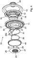
- the fitting 10 has a first fitting part 11 and a second fitting part 12, which are rotatable relative to each other.
- the two fitting parts 11 and 12 can each be approximately inscribed in a circular disk shape.
- a Umklamm réellesring 13 is provided. Such cohesion by means of a Umklamm réellesrings is for example in the US 6,799,806 B2 described.
- the preferably metallic Umklamm réellesring 13 is fixedly connected to one of the two fitting parts 11 and 12, in this case the first fitting part 11 in an outer edge portion, for example welded or crimped (at least partially in the circumferential direction).
- the first fitting part 11 for example, firmly connected to the structure of the backrest 4, so lean backrest.
- the second fitting part 12 is then firmly connected to the structure of the seat part 3, so fixed seat.
- the assignments of the fitting parts 11 and 12 may also be reversed, ie the first fitting part 11 would then be fixed seat part and the second fitting part 12 leaning.
- the fitting 10 is thus in the power flow between the back 4 and seat part 3, why the two fitting parts 11 and 12 are made of metal, preferably steel.
- the first fitting part 11 on its axially outwardly facing end face on an annular shoulder 11a, while the second fitting part 12 has a star 12a paragraph.
- the annular shoulder 11a and the star landing 12a then engage in appropriate receptacles of the structures of the back 4 and seat part 3 and are preferably welded to the edge of the receptacles.
- the fitting 10 is designed as a geared fitting, in which the first fitting part 11 and the second fitting part 12 are connected to each other by means of a gear for adjusting and locking, more precisely by means of a - in this case self-locking - eccentric epicyclic gear, as for example in the DE 44 36 101 A1 is described.
- an externally toothed gear 16 is formed on the second fitting part 12, and an internally toothed ring gear 17 is formed on the first fitting part 11, which meshes with one another.
- the diameter of the top circle of the external toothing of the toothed wheel 16 is smaller by at least one tooth height than the diameter of the root circle of the internal toothing of the ring gear 17.
- a corresponding difference of the number of teeth of toothed wheel 16 and toothed rim 17 of at least one tooth enables a rolling movement of the ring gear 17 on the toothed wheel 16
- the formation of gear 16 and ring gear 17 is preferably carried out by means of a single embossing-stamping operation, which also punches the fittings 11 and 12 from their starting material.
- the fitting parts 11 and 12 - with similar geometries and the same functions - by massive forming can be produced.
- the gear 16 forms the radially outer edge of the second fitting part 12, i. the second fitting part 12 terminates radially outwardly with the gear 16.
- One of the two fitting parts 11 and 12 has a collar 19, in this case the second fitting part 12 concentric with the gear 16.
- the collar 19 may be formed as a collar on the said fitting part (ie integrally formed) or be attached as a separate sleeve.
- a driver 21 is rotatably supported by a hub 22.
- the driver 21 is preferably made of plastic.
- the hub 22 of the driver 21 is centrally provided with a bore 23 for receiving the drive shaft 7.
- the profile of the bore 23 is matched to the profile of the drive shaft 7, in this case a splined shaft profile formed.
- the driver 21 has an integrally formed with the hub 22 cover plate 25 with a larger diameter than the hub 22.
- the driver 21 has - radially spaced from the hub 22 - with a game between the narrow sides of the wedge segments 27 grasping driver segment 29, which is formed integrally with the cover plate 25 and the hub 22.
- the wedge segments 27, the broad sides are facing each other, take, for example, each with an opening or a recess defined by projecting material parts, each an angled end finger 35a of an omega-shaped spring 35.
- the spring 35 acts on the wedge segments 27 in the circumferential direction, in particular in order to press them apart, wherein in operation, the broad sides of the wedge segments 27 can touch and act on each other.
- the driver 21 is axially secured on the outside of the collar 19 having the fitting part by a preferably clipped securing ring 43.
- the securing ring 43 extends in the axial direction along a part of the hub 22, so that the hub 22 does not bear directly on the inside of the collar 19, but is mounted in the collar 19 with the interposition of the securing ring 43 (And thereby the driver 21 is mounted on the second fitting part 12).
- the sealing ring 44 may also be formed of metal and firmly connected to the first fitting part 11, for example welded, be, in which case the cover plate 25 is movable relative to the sealing ring 44.
- an eccentric which presses the gear 16 at an engagement point in the ring gear 17 in extension of the direction of eccentricity.
- a torque is first transmitted to the driver 21 and then by means of the driver segment 29 on the eccentric so defined, which slides along the plain bearing bush 28 with displacement of the direction of eccentricity and thus under displacement of Engagement point of the gear 16 in the ring gear 17, which is a tumbling rolling motion, ie as relative rotation with superimposed wobble.
- the inclination of the backrest 4 is thereby continuously adjustable between several positions of use.
- a locking spring 51 is provided, as for example in the DE 195 48 809 C1 is disclosed.
- the locking spring 51 cooperates in the present case with a toothing 55, which is formed as a further toothed rim on the first fitting part 11.
- the locking spring 51 locks each of the wedge segments 27 in the non-driven state (by the locking spring 51 by means of engagement with the end fingers 35a, the spring 35 locks) and is released by the driven driver 21.
- the fitting 10 can be executed in different load classes.
- the inner components (or portions of components) for all load classes designed the same, ie in particular the collar 19 of the second fitting part 12 (more precisely the section of the collar 19 in contact with the wedge segments 27 in terms of inner diameter and outer diameter), the wedge segments 27, the plain bearing bush 28 and the receiving of the first fitting part 11 lined by it.
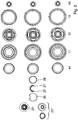
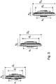
- the outer components of the fitting 10 are designed for the individual load classes, ie in particular the first fitting part 11 with the ring gear 17, the second fitting part 12 with the gear 16 and the Umklamm ceremoniessring 13. These outer components are parameterized, i. their dimensions depend on the load class. It dominate the sprocket 17 and the gear 16. Their diameter and axial dimension (“depth”) are important parameters, as well as the tooth height, the tooth width and the tooth spacing, indirectly thereby also the number of teeth. After these parameters of the ring gear 17 and the gear 16, the outer dimensions of the first fitting part 11 and the second fitting part 12, in particular the outer diameter and the axial dimension determine, and consequently also the outer dimensions of the Umklamm réellesrings 13th
- the outside diameter D2 of the middle load class is about 7% larger than the outer diameter D1 of the small load class. From load class to load class (depending on the material), the weight also increases by 20% - 30%.
- the different axial dimensions a1, a2, a3 are preferably compensated by different retaining rings 43.
- the clearly small outside diameter D1 of the small load class requires a smaller ring diameter d1 of the annular shoulder 11a (and a smaller star diameter s1 of the star shoulder 12a), so that optionally the voltage applied to the annular shoulder 11a sealing ring 44 is not the same part, but for the small load class own sealing ring 44th exists, ie the sealing ring 44 is a parameterized component of the fitting 10.
- the first fitting part 11 preferably has a thickness of 3.0 mm ⁇ 5%, a tip diameter of 62 mm ⁇ 3%, a pitch diameter of 65 mm ⁇ 3% and a number of teeth of preferably 34.
- the first fitting part 11 preferably has a thickness of 3.5 mm ⁇ 5%, a tip diameter of 65 mm ⁇ 3%, a root diameter of 70 mm ⁇ 3% and a number of teeth of preferably 37.
- the first fitting part 11 preferably has a thickness of 4.0 mm ⁇ 5%, a tip diameter of 65 mm ⁇ 3%, a root diameter of 70 mm ⁇ 3% and a number of teeth preferably 37 Admission for the plain bearing bushing 28 is 33 mm ⁇ 3%.
- the first fitting part 11 is preferably made of high-strength steel without heat treatment, alternatively made of C20E steel, which is tempered by a heat treatment.
- the second fitting part 12 preferably has a thickness of 3.0 mm ⁇ 5%, a tip diameter of 62 mm ⁇ 3%, a root diameter of 57 mm ⁇ 3% and a number of teeth of preferably 33.
- the second fitting part 12 preferably has a thickness of 3.5 mm ⁇ 5%, a tip diameter of 67 mm ⁇ 3%, a root diameter of 61 mm ⁇ 3% and a number of teeth of preferably 36.
- the second fitting part 12 preferably has a thickness of 4.0 mm ⁇ 5%, a tip diameter of 67 mm ⁇ 3%, a root diameter of 61 mm ⁇ 3% and a number of teeth of preferably 36 ..
- the outer diameter of the collar 19 is in each case 21 mm ⁇ 3%.
- the fitting 10 is assembled from the above identical parts and parameterized components in the manner of a construction kit, i. one of the load classes is specified, and then - depending on this given load class, the parameterized components that are assigned to the given load class and the components that are the same parts for all load classes are selected (and taken from this kit), and the fitting 10 is assembled from it.
- a construction kit i. one of the load classes is specified, and then - depending on this given load class, the parameterized components that are assigned to the given load class and the components that are the same parts for all load classes are selected (and taken from this kit), and the fitting 10 is assembled from it.
- the differently parameterized components different markings, for example, a different color in the plastic parts.
- the system of identical parts and parameterized components of the fitting 10 can be extended to the motor variants as described in the US 7,314,250 B1 for a metallic, one-piece driver 21 ', for example, zinc or aluminum die casting, and in the US 2009/0127910 A1 is described for a two-part driver 21 "of a metallic ring (preferably a sintered material) with driver segment 29 and a rotatably connected plastic component with hub 22 and cover 25.
- a metallic ring preferably a sintered material
- the three types of driver so the above-described, one-piece carrier 21 made of plastic ( DE 44 36 111 A1 ), the one-piece carrier 21 'made of metal ( US 7,314,250 ) and the two-piece driver 21 "( US 2009/0127910 A1 ) form a group.
- the driver is to be selected from this group, but is still a common part with regard to the load classes.
- the two motor variants with the metallic driver 21 'and the two-piece driver 21 " eliminates the locking spring 51st
Landscapes
- Engineering & Computer Science (AREA)
- Aviation & Aerospace Engineering (AREA)
- Transportation (AREA)
- Mechanical Engineering (AREA)
- Chairs For Special Purposes, Such As Reclining Chairs (AREA)
- Seats For Vehicles (AREA)
Priority Applications (1)
| Application Number | Priority Date | Filing Date | Title |
|---|---|---|---|
| PL11714490T PL2563618T3 (pl) | 2010-04-28 | 2011-04-01 | Okucie dla siedzenia samochodowego |
Applications Claiming Priority (2)
| Application Number | Priority Date | Filing Date | Title |
|---|---|---|---|
| DE102010018952A DE102010018952B4 (de) | 2010-04-28 | 2010-04-28 | Beschlag für einen Fahrzeugsitz, Fahrzeugsitz und Verfahren zum Zusammenbau eines Beschlags |
| PCT/EP2011/001661 WO2011134584A1 (de) | 2010-04-28 | 2011-04-01 | Beschlag für einen fahrzeugsitz |
Publications (2)
| Publication Number | Publication Date |
|---|---|
| EP2563618A1 EP2563618A1 (de) | 2013-03-06 |
| EP2563618B1 true EP2563618B1 (de) | 2017-08-02 |
Family
ID=44279804
Family Applications (1)
| Application Number | Title | Priority Date | Filing Date |
|---|---|---|---|
| EP11714490.7A Revoked EP2563618B1 (de) | 2010-04-28 | 2011-04-01 | Beschlag für einen fahrzeugsitz |
Country Status (8)
| Country | Link |
|---|---|
| US (1) | US8905479B2 (ja) |
| EP (1) | EP2563618B1 (ja) |
| JP (1) | JP5449582B2 (ja) |
| KR (1) | KR101394942B1 (ja) |
| CN (1) | CN102781718B (ja) |
| DE (1) | DE102010018952B4 (ja) |
| PL (1) | PL2563618T3 (ja) |
| WO (1) | WO2011134584A1 (ja) |
Families Citing this family (10)
| Publication number | Priority date | Publication date | Assignee | Title |
|---|---|---|---|---|
| DE102010018952B4 (de) | 2010-04-28 | 2013-03-14 | Keiper Gmbh & Co. Kg | Beschlag für einen Fahrzeugsitz, Fahrzeugsitz und Verfahren zum Zusammenbau eines Beschlags |
| CN103129418B (zh) * | 2011-11-25 | 2015-03-25 | 湖北中航精机科技有限公司 | 一种座椅调角器及其座椅 |
| KR101372952B1 (ko) * | 2012-03-06 | 2014-03-10 | 현대다이모스(주) | 차량 시트용 리클라이닝 장치 |
| DE102012024643B3 (de) * | 2012-09-18 | 2014-03-20 | Keiper Gmbh & Co. Kg | Fahrzeugsitz, insbesondere Kraftfahrzeug-Rücksitzanlage |
| CN104583002B (zh) * | 2013-06-27 | 2017-03-01 | 达世株式会社 | 车座调角器 |
| CN104405830B (zh) * | 2014-09-17 | 2017-02-15 | 西安交通大学 | 一种星轮齿的两侧面圆柱包络型线的协同构造方法 |
| EP3385165A1 (en) | 2017-04-03 | 2018-10-10 | Adient US LLC | A seat for a vehicle |
| IT201800004672A1 (it) * | 2018-04-18 | 2019-10-18 | Dispositivo di reclinazione per un sedile di veicolo | |
| MA52825B1 (fr) * | 2018-09-25 | 2021-09-30 | Martur Italy Srl | Dispositif d'inclinaison pour un siège de véhicule |
| DE102019216677A1 (de) * | 2019-10-29 | 2021-04-29 | Brose Fahrzeugteile SE & Co. Kommanditgesellschaft, Coburg | Fahrzeugsitz mit unterschiedlich großen Drehbeschlägen |
Citations (24)
| Publication number | Priority date | Publication date | Assignee | Title |
|---|---|---|---|---|
| DE4436101A1 (de) | 1993-11-30 | 1995-06-01 | Keiper Recaro Gmbh Co | Gelenkbeschlag für Sitze mit verstellbarer Rückenlehne, insbesondere Kraftfahrzeugsitze |
| DE19548809C1 (de) | 1995-12-27 | 1997-05-22 | Keiper Recaro Gmbh Co | Ver- und Feststelleinrichtung für Sitze, wie Kraftfahrzeugsitze, zur Verstellung der Rückenlehne |
| DE19938666A1 (de) | 1999-08-14 | 2001-02-22 | Keiper Gmbh & Co | Verstellbeschlag für Sitze mit neigungseinstellbarer Lehne, insbesondere für Kraftfahzeugsitze |
| WO2002064397A1 (de) | 2001-02-12 | 2002-08-22 | Volkswagen Aktiengesellschaft | Verstelleinrichtung zur drehverstellung zweier zentrisch gelagerter adapterstücke, insbesondere für einen sitz vorzugsweise eines kraftfahrzeuges, und planetengetriebe hierfür |
| US6799806B2 (en) | 2001-02-06 | 2004-10-05 | Keiper Gmbh & Co. Kg | Fitting for a vehicle seat |
| DE20023584U1 (de) | 1999-01-28 | 2004-12-16 | Keiper Gmbh & Co. Kg | Rastbeschlag für einen Fahrzeugsitz |
| DE102004007045B3 (de) | 2004-02-12 | 2005-06-02 | Keiper Gmbh & Co. Kg | Beschlag für einen Fahrzeugsitz |
| DE10157273B4 (de) | 2001-11-22 | 2006-01-19 | Faurecia Autositze Gmbh & Co. Kg | Verstellbeschlag für einen Kraftfahrzeugsitz, insbesondere Neigungsverstellbeschlag für dessen Rückenlehne |
| DE102004013272B3 (de) | 2004-03-18 | 2006-01-26 | Faurecia Autositze Gmbh & Co. Kg | Neigungsverstellbeschlag für die Rückenlehne eines Kraftfahrzeugsitzes |
| DE102005028779A1 (de) | 2005-06-22 | 2006-12-28 | Keiper Gmbh & Co.Kg | Beschlag für einen Fahrzeugsitz |
| US7314250B1 (en) | 2006-09-27 | 2008-01-01 | Keiper Gmbh & Co. Kg | Fitting system for a vehicle seat |
| WO2008028549A1 (de) | 2006-09-07 | 2008-03-13 | Keiper Gmbh & Co. Kg | Übertragungsvorrichtung für einen fahrzeugsitz |
| WO2008080999A1 (de) | 2007-01-04 | 2008-07-10 | Johnson Controls Gmbh | Verstelleinrichtung für einen fahrzeugsitz |
| DE102007010078A1 (de) | 2007-02-28 | 2008-09-04 | Johnson Controls Gmbh | Verstellbeschlag für eine Kraftfahrzeugkomponente und Verfahren zur Sicherung der Arretierung eines Verstellbeschlags |
| DE102007011998A1 (de) | 2007-03-09 | 2008-09-11 | Johnson Controls Gmbh | Fahrzeugsitz mit einem Taumelrecliner |
| DE102007042602A1 (de) | 2007-09-07 | 2009-03-12 | Johnson Controls Gmbh | Neigungsversteller für Fahrzeuge |
| US20090127910A1 (en) | 2007-11-20 | 2009-05-21 | Keiper Gmbh & Co. Kg | Fitting for a vehicle seat |
| US7571962B2 (en) | 2006-01-24 | 2009-08-11 | Keiper Gmbh & Co. Kg | Fitting for a vehicle seat |
| DE202009007521U1 (de) | 2009-02-27 | 2009-08-20 | Keiper Gmbh & Co. Kg | Beschlag für einen Fahrzeugsitz |
| DE102008028475A1 (de) | 2008-05-16 | 2009-11-19 | Brose Fahrzeugteile Gmbh & Co. Kommanditgesellschaft, Coburg | Beschlaganordnung für einen Sitz, insbesondere Fahrzeugsitz sowie Verfahren zur Montage einer solchen Beschlaganordnung |
| WO2009149875A2 (de) | 2008-06-13 | 2009-12-17 | Brose Fahrzeugteile Gmbh & Co. | Verfahren zur herstellung eines verstellbeschlages |
| DE102008028102A1 (de) | 2008-06-13 | 2009-12-17 | Brose Fahrzeugteile Gmbh & Co. Kommanditgesellschaft, Coburg | Verstellbeschlag |
| DE102008028103A1 (de) | 2008-06-13 | 2009-12-17 | Brose Fahrzeugteile Gmbh & Co. Kommanditgesellschaft, Coburg | Verstellbeschlag |
| DE202009015236U1 (de) | 2009-09-10 | 2011-02-03 | Keiper Gmbh & Co. Kg | Beschlag für einen Fahrzeugsitz |
Family Cites Families (20)
| Publication number | Priority date | Publication date | Assignee | Title |
|---|---|---|---|---|
| DE4436111C1 (de) | 1994-10-10 | 1996-01-18 | Fichtel & Sachs Ag | Reibungskupplung mit Verschleißausgleich |
| WO2003024740A1 (de) * | 2001-09-06 | 2003-03-27 | Keiper Gmbh & Co | Beschlag für einen fahrzeugsitz |
| DE10328300B4 (de) * | 2003-06-23 | 2006-09-21 | Faurecia Autositze Gmbh & Co. Kg | Verstellbeschlag für Kraftfahrzeugsitz |
| JP4414158B2 (ja) | 2003-07-04 | 2010-02-10 | シロキ工業株式会社 | 両側リクライニング装置の組付け方法 |
| DE102004007043B3 (de) * | 2004-02-12 | 2005-06-23 | Keiper Gmbh & Co. Kg | Beschlag für einen Fahrzeugsitz |
| DE102004062050B4 (de) * | 2004-12-23 | 2006-12-07 | Keiper Gmbh & Co.Kg | Beschlag für einen Fahrzeugsitz |
| DE102005046357A1 (de) * | 2005-09-28 | 2007-03-29 | Robert Bosch Gmbh | Getriebe-Antriebseinheit, insbesondere zum Verstellen eines beweglichen Teils im Kraftfahrzeug, mit einem Trägerrohr |
| DE102006015558B3 (de) * | 2006-04-04 | 2008-02-14 | Keiper Gmbh & Co.Kg | Beschlag für einen Fahrzeugsitz |
| DE102006015559B3 (de) * | 2006-04-04 | 2007-08-16 | Keiper Gmbh & Co.Kg | Beschlag für einen Fahrzeugsitz |
| DE102007007362B4 (de) * | 2007-02-14 | 2009-07-09 | Faurecia Autositze Gmbh | Verstellmechanismus |
| CN101677689B (zh) * | 2007-05-08 | 2011-05-11 | 丰田纺织株式会社 | 连接装置 |
| US8460145B2 (en) * | 2007-06-11 | 2013-06-11 | Toyota Boshoku Kabushiki Kaisha | Rotation mechanism |
| DE102007059510C5 (de) * | 2007-12-07 | 2011-05-12 | Keiper Gmbh & Co. Kg | Element für einen Fahrzeugsitz |
| JP5414299B2 (ja) * | 2008-03-04 | 2014-02-12 | ツェー ロブ ハメルステイン ゲーエムベーハー ウント コー カーゲー | 自動車シート調節装置用、特に背もたれヒンジ部品用の揺動継手部品 |
| JP5338165B2 (ja) * | 2008-07-15 | 2013-11-13 | トヨタ紡織株式会社 | 歯車及びこの歯車を用いた連結装置 |
| JP5077115B2 (ja) * | 2008-07-15 | 2012-11-21 | トヨタ紡織株式会社 | 歯車及びこの歯車を用いた連結装置 |
| EP2313291A1 (de) * | 2008-08-13 | 2011-04-27 | C. Rob. Hammerstein GmbH & Co. Kg | Taumelgelenkbeschlag für einen fahrzeugsitz |
| CN101941389B (zh) * | 2009-07-04 | 2012-06-20 | 湖北中航精机科技股份有限公司 | 座椅调角器及具有该调角器的座椅 |
| DE102009052582B3 (de) * | 2009-11-04 | 2011-02-24 | Keiper Gmbh & Co. Kg | Einsteller für einen Fahrzeugsitz und Fahrzeugsitz hierzu |
| DE102010018952B4 (de) | 2010-04-28 | 2013-03-14 | Keiper Gmbh & Co. Kg | Beschlag für einen Fahrzeugsitz, Fahrzeugsitz und Verfahren zum Zusammenbau eines Beschlags |
-
2010
- 2010-04-28 DE DE102010018952A patent/DE102010018952B4/de not_active Revoked
-
2011
- 2011-04-01 KR KR1020127031057A patent/KR101394942B1/ko active IP Right Grant
- 2011-04-01 WO PCT/EP2011/001661 patent/WO2011134584A1/de active Application Filing
- 2011-04-01 US US13/643,286 patent/US8905479B2/en active Active
- 2011-04-01 CN CN201180011881.1A patent/CN102781718B/zh active Active
- 2011-04-01 JP JP2012557454A patent/JP5449582B2/ja active Active
- 2011-04-01 EP EP11714490.7A patent/EP2563618B1/de not_active Revoked
- 2011-04-01 PL PL11714490T patent/PL2563618T3/pl unknown
Patent Citations (25)
| Publication number | Priority date | Publication date | Assignee | Title |
|---|---|---|---|---|
| DE4436101A1 (de) | 1993-11-30 | 1995-06-01 | Keiper Recaro Gmbh Co | Gelenkbeschlag für Sitze mit verstellbarer Rückenlehne, insbesondere Kraftfahrzeugsitze |
| DE19548809C1 (de) | 1995-12-27 | 1997-05-22 | Keiper Recaro Gmbh Co | Ver- und Feststelleinrichtung für Sitze, wie Kraftfahrzeugsitze, zur Verstellung der Rückenlehne |
| DE20023584U1 (de) | 1999-01-28 | 2004-12-16 | Keiper Gmbh & Co. Kg | Rastbeschlag für einen Fahrzeugsitz |
| DE19938666A1 (de) | 1999-08-14 | 2001-02-22 | Keiper Gmbh & Co | Verstellbeschlag für Sitze mit neigungseinstellbarer Lehne, insbesondere für Kraftfahzeugsitze |
| US6799806B2 (en) | 2001-02-06 | 2004-10-05 | Keiper Gmbh & Co. Kg | Fitting for a vehicle seat |
| WO2002064397A1 (de) | 2001-02-12 | 2002-08-22 | Volkswagen Aktiengesellschaft | Verstelleinrichtung zur drehverstellung zweier zentrisch gelagerter adapterstücke, insbesondere für einen sitz vorzugsweise eines kraftfahrzeuges, und planetengetriebe hierfür |
| DE10157273B4 (de) | 2001-11-22 | 2006-01-19 | Faurecia Autositze Gmbh & Co. Kg | Verstellbeschlag für einen Kraftfahrzeugsitz, insbesondere Neigungsverstellbeschlag für dessen Rückenlehne |
| DE102004007045B3 (de) | 2004-02-12 | 2005-06-02 | Keiper Gmbh & Co. Kg | Beschlag für einen Fahrzeugsitz |
| DE102004013272B3 (de) | 2004-03-18 | 2006-01-26 | Faurecia Autositze Gmbh & Co. Kg | Neigungsverstellbeschlag für die Rückenlehne eines Kraftfahrzeugsitzes |
| DE102005028779A1 (de) | 2005-06-22 | 2006-12-28 | Keiper Gmbh & Co.Kg | Beschlag für einen Fahrzeugsitz |
| US7571962B2 (en) | 2006-01-24 | 2009-08-11 | Keiper Gmbh & Co. Kg | Fitting for a vehicle seat |
| WO2008028549A1 (de) | 2006-09-07 | 2008-03-13 | Keiper Gmbh & Co. Kg | Übertragungsvorrichtung für einen fahrzeugsitz |
| US7314250B1 (en) | 2006-09-27 | 2008-01-01 | Keiper Gmbh & Co. Kg | Fitting system for a vehicle seat |
| WO2008080999A1 (de) | 2007-01-04 | 2008-07-10 | Johnson Controls Gmbh | Verstelleinrichtung für einen fahrzeugsitz |
| DE102007010078A1 (de) | 2007-02-28 | 2008-09-04 | Johnson Controls Gmbh | Verstellbeschlag für eine Kraftfahrzeugkomponente und Verfahren zur Sicherung der Arretierung eines Verstellbeschlags |
| DE102007011998A1 (de) | 2007-03-09 | 2008-09-11 | Johnson Controls Gmbh | Fahrzeugsitz mit einem Taumelrecliner |
| DE102007042602A1 (de) | 2007-09-07 | 2009-03-12 | Johnson Controls Gmbh | Neigungsversteller für Fahrzeuge |
| US20090127910A1 (en) | 2007-11-20 | 2009-05-21 | Keiper Gmbh & Co. Kg | Fitting for a vehicle seat |
| DE102008028475A1 (de) | 2008-05-16 | 2009-11-19 | Brose Fahrzeugteile Gmbh & Co. Kommanditgesellschaft, Coburg | Beschlaganordnung für einen Sitz, insbesondere Fahrzeugsitz sowie Verfahren zur Montage einer solchen Beschlaganordnung |
| WO2009149875A2 (de) | 2008-06-13 | 2009-12-17 | Brose Fahrzeugteile Gmbh & Co. | Verfahren zur herstellung eines verstellbeschlages |
| DE102008028102A1 (de) | 2008-06-13 | 2009-12-17 | Brose Fahrzeugteile Gmbh & Co. Kommanditgesellschaft, Coburg | Verstellbeschlag |
| DE102008028103A1 (de) | 2008-06-13 | 2009-12-17 | Brose Fahrzeugteile Gmbh & Co. Kommanditgesellschaft, Coburg | Verstellbeschlag |
| DE202009007521U1 (de) | 2009-02-27 | 2009-08-20 | Keiper Gmbh & Co. Kg | Beschlag für einen Fahrzeugsitz |
| DE202009007520U1 (de) | 2009-02-27 | 2009-08-20 | Keiper Gmbh & Co. Kg | Beschlag für einen Fahrzeugsitz |
| DE202009015236U1 (de) | 2009-09-10 | 2011-02-03 | Keiper Gmbh & Co. Kg | Beschlag für einen Fahrzeugsitz |
Non-Patent Citations (1)
| Title |
|---|
| K.H.- GROTE, J. FELDHUSEN: "Dubbel Taschenbuch für den Maschinenbau 21. Auflage", 2005, SPRINGER, pages: G 134 - G 137, XP055486217 |
Also Published As
| Publication number | Publication date |
|---|---|
| DE102010018952B4 (de) | 2013-03-14 |
| JP2013522101A (ja) | 2013-06-13 |
| EP2563618A1 (de) | 2013-03-06 |
| PL2563618T3 (pl) | 2017-12-29 |
| CN102781718A (zh) | 2012-11-14 |
| KR20130020798A (ko) | 2013-02-28 |
| WO2011134584A1 (de) | 2011-11-03 |
| CN102781718B (zh) | 2015-05-20 |
| US20130207433A1 (en) | 2013-08-15 |
| US8905479B2 (en) | 2014-12-09 |
| DE102010018952A1 (de) | 2011-11-03 |
| KR101394942B1 (ko) | 2014-05-14 |
| JP5449582B2 (ja) | 2014-03-19 |
Similar Documents
| Publication | Publication Date | Title |
|---|---|---|
| EP2563618B1 (de) | Beschlag für einen fahrzeugsitz | |
| EP2566719B1 (de) | Beschlag für einen fahrzeugsitz | |
| EP2499018B1 (de) | Beschlag für einen fahrzeugsitz | |
| EP2419296B1 (de) | Antriebseinheit für einen fahrzeugsitz | |
| DE102006044490B4 (de) | Beschlag für einen Fahrzeugsitz | |
| EP1713659B1 (de) | Beschlag für einen fahrzeugsitz | |
| EP2576283B1 (de) | Beschlag für einen fahrzeugsitz | |
| EP2605933B1 (de) | Beschlag für einen fahrzeugsitz | |
| DE102010019361B3 (de) | Beschlag für einen Fahrzeugsitz sowie Fahrzeugsitz | |
| EP2550177B1 (de) | Verfahren zur herstellung eines fahrzeugsitz-beschlags | |
| EP2675656B1 (de) | Beschlag für einen fahrzeugsitz und verfahren zur herstellung desselben | |
| DE202009007521U1 (de) | Beschlag für einen Fahrzeugsitz | |
| EP2467279B1 (de) | Beschlag für einen fahrzeugsitz | |
| DE102009053250B4 (de) | Beschlag für einen Fahrzeugsitz und Fahrzeugsitz | |
| EP2580086B1 (de) | Beschlag für einen fahrzeugsitz | |
| DE202010012621U1 (de) | Beschlag für einen Fahrzeugsitz | |
| EP2755854B1 (de) | Verfahren zur herstellung eines fahrzeugsitz-beschlags | |
| DE102010051497A1 (de) | Fahrzeugsitz, insbesondere Kraftfahrzeugsitz | |
| DE102010035378B3 (de) | Verfahren zum Verbinden eines Beschlags mit einem Strukturteil eines Fahrzeugsitzes | |
| DE102010023965B4 (de) | Beschlag für einen Fahrzeugsitz |
Legal Events
| Date | Code | Title | Description |
|---|---|---|---|
| PUAI | Public reference made under article 153(3) epc to a published international application that has entered the european phase |
Free format text: ORIGINAL CODE: 0009012 |
|
| 17P | Request for examination filed |
Effective date: 20120719 |
|
| AK | Designated contracting states |
Kind code of ref document: A1 Designated state(s): AL AT BE BG CH CY CZ DE DK EE ES FI FR GB GR HR HU IE IS IT LI LT LU LV MC MK MT NL NO PL PT RO RS SE SI SK SM TR |
|
| DAX | Request for extension of the european patent (deleted) | ||
| RAP1 | Party data changed (applicant data changed or rights of an application transferred) |
Owner name: JOHNSON CONTROLS COMPONENTS GMBH & CO. KG |
|
| GRAP | Despatch of communication of intention to grant a patent |
Free format text: ORIGINAL CODE: EPIDOSNIGR1 |
|
| STAA | Information on the status of an ep patent application or granted ep patent |
Free format text: STATUS: GRANT OF PATENT IS INTENDED |
|
| INTG | Intention to grant announced |
Effective date: 20170412 |
|
| GRAS | Grant fee paid |
Free format text: ORIGINAL CODE: EPIDOSNIGR3 |
|
| GRAA | (expected) grant |
Free format text: ORIGINAL CODE: 0009210 |
|
| STAA | Information on the status of an ep patent application or granted ep patent |
Free format text: STATUS: THE PATENT HAS BEEN GRANTED |
|
| RAP1 | Party data changed (applicant data changed or rights of an application transferred) |
Owner name: ADIENT LUXEMBOURG HOLDING S.A R.L. |
|
| AK | Designated contracting states |
Kind code of ref document: B1 Designated state(s): AL AT BE BG CH CY CZ DE DK EE ES FI FR GB GR HR HU IE IS IT LI LT LU LV MC MK MT NL NO PL PT RO RS SE SI SK SM TR |
|
| REG | Reference to a national code |
Ref country code: GB Ref legal event code: FG4D Free format text: NOT ENGLISH |
|
| REG | Reference to a national code |
Ref country code: CH Ref legal event code: EP Ref country code: AT Ref legal event code: REF Ref document number: 914059 Country of ref document: AT Kind code of ref document: T Effective date: 20170815 |
|
| REG | Reference to a national code |
Ref country code: IE Ref legal event code: FG4D Free format text: LANGUAGE OF EP DOCUMENT: GERMAN |
|
| REG | Reference to a national code |
Ref country code: DE Ref legal event code: R096 Ref document number: 502011012718 Country of ref document: DE |
|
| REG | Reference to a national code |
Ref country code: NL Ref legal event code: MP Effective date: 20170802 |
|
| REG | Reference to a national code |
Ref country code: LT Ref legal event code: MG4D |
|
| PG25 | Lapsed in a contracting state [announced via postgrant information from national office to epo] |
Ref country code: HR Free format text: LAPSE BECAUSE OF FAILURE TO SUBMIT A TRANSLATION OF THE DESCRIPTION OR TO PAY THE FEE WITHIN THE PRESCRIBED TIME-LIMIT Effective date: 20170802 Ref country code: NL Free format text: LAPSE BECAUSE OF FAILURE TO SUBMIT A TRANSLATION OF THE DESCRIPTION OR TO PAY THE FEE WITHIN THE PRESCRIBED TIME-LIMIT Effective date: 20170802 Ref country code: SE Free format text: LAPSE BECAUSE OF FAILURE TO SUBMIT A TRANSLATION OF THE DESCRIPTION OR TO PAY THE FEE WITHIN THE PRESCRIBED TIME-LIMIT Effective date: 20170802 Ref country code: LT Free format text: LAPSE BECAUSE OF FAILURE TO SUBMIT A TRANSLATION OF THE DESCRIPTION OR TO PAY THE FEE WITHIN THE PRESCRIBED TIME-LIMIT Effective date: 20170802 Ref country code: FI Free format text: LAPSE BECAUSE OF FAILURE TO SUBMIT A TRANSLATION OF THE DESCRIPTION OR TO PAY THE FEE WITHIN THE PRESCRIBED TIME-LIMIT Effective date: 20170802 Ref country code: NO Free format text: LAPSE BECAUSE OF FAILURE TO SUBMIT A TRANSLATION OF THE DESCRIPTION OR TO PAY THE FEE WITHIN THE PRESCRIBED TIME-LIMIT Effective date: 20171102 |
|
| PG25 | Lapsed in a contracting state [announced via postgrant information from national office to epo] |
Ref country code: IS Free format text: LAPSE BECAUSE OF FAILURE TO SUBMIT A TRANSLATION OF THE DESCRIPTION OR TO PAY THE FEE WITHIN THE PRESCRIBED TIME-LIMIT Effective date: 20171202 Ref country code: LV Free format text: LAPSE BECAUSE OF FAILURE TO SUBMIT A TRANSLATION OF THE DESCRIPTION OR TO PAY THE FEE WITHIN THE PRESCRIBED TIME-LIMIT Effective date: 20170802 Ref country code: ES Free format text: LAPSE BECAUSE OF FAILURE TO SUBMIT A TRANSLATION OF THE DESCRIPTION OR TO PAY THE FEE WITHIN THE PRESCRIBED TIME-LIMIT Effective date: 20170802 Ref country code: RS Free format text: LAPSE BECAUSE OF FAILURE TO SUBMIT A TRANSLATION OF THE DESCRIPTION OR TO PAY THE FEE WITHIN THE PRESCRIBED TIME-LIMIT Effective date: 20170802 Ref country code: BG Free format text: LAPSE BECAUSE OF FAILURE TO SUBMIT A TRANSLATION OF THE DESCRIPTION OR TO PAY THE FEE WITHIN THE PRESCRIBED TIME-LIMIT Effective date: 20171102 Ref country code: GR Free format text: LAPSE BECAUSE OF FAILURE TO SUBMIT A TRANSLATION OF THE DESCRIPTION OR TO PAY THE FEE WITHIN THE PRESCRIBED TIME-LIMIT Effective date: 20171103 |
|
| REG | Reference to a national code |
Ref country code: DE Ref legal event code: R081 Ref document number: 502011012718 Country of ref document: DE Owner name: ADIENT LUXEMBOURG HOLDING S.A R.L., LU Free format text: FORMER OWNER: ADIENT LUXEMBOURG HOLDING S.A.R.L., LUXEMBOURG, LU |
|
| RAP2 | Party data changed (patent owner data changed or rights of a patent transferred) |
Owner name: ADIENT LUXEMBOURG HOLDING S.A R.L. |
|
| REG | Reference to a national code |
Ref country code: FR Ref legal event code: PLFP Year of fee payment: 8 |
|
| PG25 | Lapsed in a contracting state [announced via postgrant information from national office to epo] |
Ref country code: RO Free format text: LAPSE BECAUSE OF FAILURE TO SUBMIT A TRANSLATION OF THE DESCRIPTION OR TO PAY THE FEE WITHIN THE PRESCRIBED TIME-LIMIT Effective date: 20170802 Ref country code: DK Free format text: LAPSE BECAUSE OF FAILURE TO SUBMIT A TRANSLATION OF THE DESCRIPTION OR TO PAY THE FEE WITHIN THE PRESCRIBED TIME-LIMIT Effective date: 20170802 |
|
| REG | Reference to a national code |
Ref country code: DE Ref legal event code: R026 Ref document number: 502011012718 Country of ref document: DE |
|
| PLBI | Opposition filed |
Free format text: ORIGINAL CODE: 0009260 |
|
| PLAX | Notice of opposition and request to file observation + time limit sent |
Free format text: ORIGINAL CODE: EPIDOSNOBS2 |
|
| PG25 | Lapsed in a contracting state [announced via postgrant information from national office to epo] |
Ref country code: IT Free format text: LAPSE BECAUSE OF FAILURE TO SUBMIT A TRANSLATION OF THE DESCRIPTION OR TO PAY THE FEE WITHIN THE PRESCRIBED TIME-LIMIT Effective date: 20170802 Ref country code: SM Free format text: LAPSE BECAUSE OF FAILURE TO SUBMIT A TRANSLATION OF THE DESCRIPTION OR TO PAY THE FEE WITHIN THE PRESCRIBED TIME-LIMIT Effective date: 20170802 Ref country code: EE Free format text: LAPSE BECAUSE OF FAILURE TO SUBMIT A TRANSLATION OF THE DESCRIPTION OR TO PAY THE FEE WITHIN THE PRESCRIBED TIME-LIMIT Effective date: 20170802 |
|
| 26 | Opposition filed |
Opponent name: BROSE FAHRZEUGTEILE GMBH & CO. KOMMANDITGESELLSCHA Effective date: 20180502 |
|
| PG25 | Lapsed in a contracting state [announced via postgrant information from national office to epo] |
Ref country code: SI Free format text: LAPSE BECAUSE OF FAILURE TO SUBMIT A TRANSLATION OF THE DESCRIPTION OR TO PAY THE FEE WITHIN THE PRESCRIBED TIME-LIMIT Effective date: 20170802 |
|
| PLBB | Reply of patent proprietor to notice(s) of opposition received |
Free format text: ORIGINAL CODE: EPIDOSNOBS3 |
|
| PG25 | Lapsed in a contracting state [announced via postgrant information from national office to epo] |
Ref country code: MT Free format text: LAPSE BECAUSE OF FAILURE TO SUBMIT A TRANSLATION OF THE DESCRIPTION OR TO PAY THE FEE WITHIN THE PRESCRIBED TIME-LIMIT Effective date: 20170802 |
|
| PG25 | Lapsed in a contracting state [announced via postgrant information from national office to epo] |
Ref country code: MC Free format text: LAPSE BECAUSE OF FAILURE TO SUBMIT A TRANSLATION OF THE DESCRIPTION OR TO PAY THE FEE WITHIN THE PRESCRIBED TIME-LIMIT Effective date: 20170802 |
|
| REG | Reference to a national code |
Ref country code: CH Ref legal event code: PL |
|
| REG | Reference to a national code |
Ref country code: BE Ref legal event code: MM Effective date: 20180430 |
|
| GBPC | Gb: european patent ceased through non-payment of renewal fee |
Effective date: 20180401 |
|
| REG | Reference to a national code |
Ref country code: IE Ref legal event code: MM4A |
|
| PG25 | Lapsed in a contracting state [announced via postgrant information from national office to epo] |
Ref country code: LU Free format text: LAPSE BECAUSE OF NON-PAYMENT OF DUE FEES Effective date: 20180401 |
|
| PG25 | Lapsed in a contracting state [announced via postgrant information from national office to epo] |
Ref country code: LI Free format text: LAPSE BECAUSE OF NON-PAYMENT OF DUE FEES Effective date: 20180430 Ref country code: CH Free format text: LAPSE BECAUSE OF NON-PAYMENT OF DUE FEES Effective date: 20180430 Ref country code: BE Free format text: LAPSE BECAUSE OF NON-PAYMENT OF DUE FEES Effective date: 20180430 Ref country code: GB Free format text: LAPSE BECAUSE OF NON-PAYMENT OF DUE FEES Effective date: 20180401 |
|
| PG25 | Lapsed in a contracting state [announced via postgrant information from national office to epo] |
Ref country code: IE Free format text: LAPSE BECAUSE OF NON-PAYMENT OF DUE FEES Effective date: 20180401 |
|
| PGFP | Annual fee paid to national office [announced via postgrant information from national office to epo] |
Ref country code: PL Payment date: 20190322 Year of fee payment: 9 |
|
| REG | Reference to a national code |
Ref country code: AT Ref legal event code: MM01 Ref document number: 914059 Country of ref document: AT Kind code of ref document: T Effective date: 20180401 |
|
| PGFP | Annual fee paid to national office [announced via postgrant information from national office to epo] |
Ref country code: SK Payment date: 20190328 Year of fee payment: 9 |
|
| PGFP | Annual fee paid to national office [announced via postgrant information from national office to epo] |
Ref country code: CZ Payment date: 20190329 Year of fee payment: 9 Ref country code: DE Payment date: 20190430 Year of fee payment: 9 |
|
| PGFP | Annual fee paid to national office [announced via postgrant information from national office to epo] |
Ref country code: FR Payment date: 20190418 Year of fee payment: 9 |
|
| PG25 | Lapsed in a contracting state [announced via postgrant information from national office to epo] |
Ref country code: AT Free format text: LAPSE BECAUSE OF NON-PAYMENT OF DUE FEES Effective date: 20180401 |
|
| RDAF | Communication despatched that patent is revoked |
Free format text: ORIGINAL CODE: EPIDOSNREV1 |
|
| REG | Reference to a national code |
Ref country code: DE Ref legal event code: R064 Ref document number: 502011012718 Country of ref document: DE Ref country code: DE Ref legal event code: R103 Ref document number: 502011012718 Country of ref document: DE |
|
| RDAG | Patent revoked |
Free format text: ORIGINAL CODE: 0009271 |
|
| STAA | Information on the status of an ep patent application or granted ep patent |
Free format text: STATUS: PATENT REVOKED |
|
| PG25 | Lapsed in a contracting state [announced via postgrant information from national office to epo] |
Ref country code: TR Free format text: LAPSE BECAUSE OF FAILURE TO SUBMIT A TRANSLATION OF THE DESCRIPTION OR TO PAY THE FEE WITHIN THE PRESCRIBED TIME-LIMIT Effective date: 20170802 |
|
| 27W | Patent revoked |
Effective date: 20191213 |
|
| REG | Reference to a national code |
Ref country code: FI Ref legal event code: MGE |
|
| PG25 | Lapsed in a contracting state [announced via postgrant information from national office to epo] |
Ref country code: PT Free format text: LAPSE BECAUSE OF FAILURE TO SUBMIT A TRANSLATION OF THE DESCRIPTION OR TO PAY THE FEE WITHIN THE PRESCRIBED TIME-LIMIT Effective date: 20170802 Ref country code: CY Free format text: LAPSE BECAUSE OF FAILURE TO SUBMIT A TRANSLATION OF THE DESCRIPTION OR TO PAY THE FEE WITHIN THE PRESCRIBED TIME-LIMIT Effective date: 20170802 |
|
| REG | Reference to a national code |
Ref country code: SK Ref legal event code: MC4A Ref document number: E 25642 Country of ref document: SK Effective date: 20191213 |
|
| PG25 | Lapsed in a contracting state [announced via postgrant information from national office to epo] |
Ref country code: MK Free format text: LAPSE BECAUSE OF NON-PAYMENT OF DUE FEES Effective date: 20170802 |
|
| PG25 | Lapsed in a contracting state [announced via postgrant information from national office to epo] |
Ref country code: AL Free format text: LAPSE BECAUSE OF FAILURE TO SUBMIT A TRANSLATION OF THE DESCRIPTION OR TO PAY THE FEE WITHIN THE PRESCRIBED TIME-LIMIT Effective date: 20170802 |
|
| REG | Reference to a national code |
Ref country code: AT Ref legal event code: MA03 Ref document number: 914059 Country of ref document: AT Kind code of ref document: T Effective date: 20191213 |