EP2556766B1 - Verschlussleiste und reissverschluss - Google Patents
Verschlussleiste und reissverschluss Download PDFInfo
- Publication number
- EP2556766B1 EP2556766B1 EP10849420.4A EP10849420A EP2556766B1 EP 2556766 B1 EP2556766 B1 EP 2556766B1 EP 10849420 A EP10849420 A EP 10849420A EP 2556766 B1 EP2556766 B1 EP 2556766B1
- Authority
- EP
- European Patent Office
- Prior art keywords
- fastener
- recesses
- fastener element
- bosses
- tape
- Prior art date
- Legal status (The legal status is an assumption and is not a legal conclusion. Google has not performed a legal analysis and makes no representation as to the accuracy of the status listed.)
- Active
Links
Images



Classifications
-
- A—HUMAN NECESSITIES
- A44—HABERDASHERY; JEWELLERY
- A44B—BUTTONS, PINS, BUCKLES, SLIDE FASTENERS, OR THE LIKE
- A44B19/00—Slide fasteners
- A44B19/02—Slide fasteners with a series of separate interlocking members secured to each stringer tape
- A44B19/04—Stringers arranged edge-to-edge when fastened, e.g. abutting stringers
- A44B19/06—Stringers arranged edge-to-edge when fastened, e.g. abutting stringers with substantially rectangular members having interlocking projections and pieces
-
- A—HUMAN NECESSITIES
- A44—HABERDASHERY; JEWELLERY
- A44B—BUTTONS, PINS, BUCKLES, SLIDE FASTENERS, OR THE LIKE
- A44B19/00—Slide fasteners
- A44B19/24—Details
- A44B19/26—Sliders
-
- A—HUMAN NECESSITIES
- A44—HABERDASHERY; JEWELLERY
- A44B—BUTTONS, PINS, BUCKLES, SLIDE FASTENERS, OR THE LIKE
- A44B19/00—Slide fasteners
- A44B19/24—Details
- A44B19/36—Means for permanently uniting the stringers at the end; Means for stopping movement of slider at the end
-
- A—HUMAN NECESSITIES
- A44—HABERDASHERY; JEWELLERY
- A44B—BUTTONS, PINS, BUCKLES, SLIDE FASTENERS, OR THE LIKE
- A44B19/00—Slide fasteners
- A44B19/24—Details
- A44B19/38—Means at the end of stringer by which the slider can be freed from one stringer, e.g. stringers can be completely separated from each other
-
- Y—GENERAL TAGGING OF NEW TECHNOLOGICAL DEVELOPMENTS; GENERAL TAGGING OF CROSS-SECTIONAL TECHNOLOGIES SPANNING OVER SEVERAL SECTIONS OF THE IPC; TECHNICAL SUBJECTS COVERED BY FORMER USPC CROSS-REFERENCE ART COLLECTIONS [XRACs] AND DIGESTS
- Y10—TECHNICAL SUBJECTS COVERED BY FORMER USPC
- Y10T—TECHNICAL SUBJECTS COVERED BY FORMER US CLASSIFICATION
- Y10T24/00—Buckles, buttons, clasps, etc.
- Y10T24/25—Zipper or required component thereof
-
- Y—GENERAL TAGGING OF NEW TECHNOLOGICAL DEVELOPMENTS; GENERAL TAGGING OF CROSS-SECTIONAL TECHNOLOGIES SPANNING OVER SEVERAL SECTIONS OF THE IPC; TECHNICAL SUBJECTS COVERED BY FORMER USPC CROSS-REFERENCE ART COLLECTIONS [XRACs] AND DIGESTS
- Y10—TECHNICAL SUBJECTS COVERED BY FORMER USPC
- Y10T—TECHNICAL SUBJECTS COVERED BY FORMER US CLASSIFICATION
- Y10T24/00—Buckles, buttons, clasps, etc.
- Y10T24/25—Zipper or required component thereof
- Y10T24/2539—Interlocking surface constructed from plural elements in series
- Y10T24/2543—Interlocking surface constructed from plural elements in series with element structural feature unrelated to interlocking or securing portion
-
- Y—GENERAL TAGGING OF NEW TECHNOLOGICAL DEVELOPMENTS; GENERAL TAGGING OF CROSS-SECTIONAL TECHNOLOGIES SPANNING OVER SEVERAL SECTIONS OF THE IPC; TECHNICAL SUBJECTS COVERED BY FORMER USPC CROSS-REFERENCE ART COLLECTIONS [XRACs] AND DIGESTS
- Y10—TECHNICAL SUBJECTS COVERED BY FORMER USPC
- Y10T—TECHNICAL SUBJECTS COVERED BY FORMER US CLASSIFICATION
- Y10T24/00—Buckles, buttons, clasps, etc.
- Y10T24/25—Zipper or required component thereof
- Y10T24/2561—Slider having specific configuration, construction, adaptation, or material
- Y10T24/2589—Slider having specific configuration, construction, adaptation, or material with ornamental slider
Definitions
- the invention relates to a fastener stringer where fastener elements together with a fastener tape are colored by a coloring agent, and a slide fastener including the fastener stringer.
- a slide fastener is manufactured by mounting synthetic resin or metallic fastener elements to opposite marginal part of woven or knitted fastener tapes to form fastener stringers, and slidably mounting a slider to element rows of the left and right fastener stringers where one set has two obtained stringers.
- the opposite fastener elements are coupled and released.
- a method of attaching a thermal transfer sheet having a predetermined pattern to a fastener stringer and then heat-treating the fastener stringer to transfer the pattern onto the fastener stringer a method of printing a predetermined pattern on a fastener stringer through an inkjet method and then heat-treating the fastener stringer to color the fastener stringer, and the like are well known.
- Patent Document 1 Japanese Patent Application Laid-Open No. 4-24004
- a pattern is formed on a surface of the slide fastener by ejecting ink droplets from an inkjet nozzle onto a surface of the slide fastener including synthetic resin fastener elements.
- a dye attached to the slide fastener is dyed onto a fastener tape and fastener elements by heat-treating the slide fastener to which the pattern is given.
- Patent Document 2 discloses a slide fastener where a large recess (or groove) is formed on a surface of a fastener element.
- the recess is basically a design of the fastener element and is formed on the surface of the element decoratively. According to Patent Document 2, after the fastener element is coated or plated, a filling material is filled in the recess of the fastener element, making it possible to show a color difference on the surface of the fastener element.
- the filling material is apt to drop out from the fastener element due to friction or impact applied to the fastener element.
- piece-dyeing (also, called beam-dyeing) is generally known as a method of dyeing a fastener stringer (or fastener chain).
- a fastener stringer is wound on a dyeing beam, and the beam on which the fastener stringer is wound is accommodated in a dyeing pot to be dyed.
- the fastener stringer is dyed by using piece-dyeing
- the surfaces of the 5 fastener element wound on a layer and the rear surfaces of the fastener element wound on the next layer are apt to be close to each other.
- the fastener stringer wound on the beam is dyed in the dyeing pot, it is difficult to widely spread the dye on the surface and rear surface of the fastener element, and there is a case where dyeing stains are generated in the dyed fastener element.
- the invention has been made in an effort to solve the above-described problems, and the object of the invention is to provide a fastener stringer which may neatly provide a desired pattern or color a like a fastener tape when the fastener element attached to the fastener tape is colored through an inkjet method, and may be 15 stably colored without generating color stains by widely spreading a dye on a surface of an element when the element is dyed through piece-dyeing, and to provide a slide fastener constituted by using such fastener stringer.
- JP4024004A discloses a fastener stringer including a fastener tape, and a plurality of fastener elements attached along one marginal part of the fastener tape, at least one surface of each of the fastener elements being colored or surface-treated.
- the invention is in the fastener stringer of Claim 1.
- recesses or bosses are disposed at a ratio of one to twenty five recesses or bosses per 1 mm 2 on the at least one surface of the fastener element which is dyed or painted, and the fine fixing spaces are defined by spaces formed in the recesses, or spaces formed between the bosses.
- a predetermined interval is formed between the adjacent recesses or the adjacent bosses.
- the recesses or the bosses are formed to have a semispherical shape, a conic shape, or a frustum shape.
- a capacity of a space formed in the recesses or between the bosses is set to 0.002 mm 3 to 0.27 mm 3 .
- the plurality of recesses or bosses disposed on the one surface of the fastener element is formed to have the same shapes or similar shapes. Further, it is preferable that the plurality of recesses or bosses disposed on the one surface of the fastener element is disposed in zigzag.
- the recesses or bosses may be formed to have a groove shape or a ridge shape along a predetermined direction.
- the fastener element is colored through an inkjet method, and in particular, it is preferable that the fastener element and the fastener tape are colored to have a pattern.
- the fastener element may be colored through post dyeing.
- the fastener element has a body fixedly attached to the fastener tape, a neck extending from the body to a tape outer side, and a coupling head disposed at a tip end of the neck, and a side wall surface of the body facing a tape inner side is formed to be flat.
- the plurality of recesses or bosses is formed at a ratio of one to twenty five recesses or bosses per 1 mm 2 on a surface facing the same direction as one surface on which the recesses or bosses of the fastener element are disposed.
- the dyeing or painting performed on the fastener element is not specifically limited.
- a method of performing the coloring by using a dye ink or a pigment ink through the above-described inkjet method may be property used, or a method of piece-dyeing or painting through ejection may be used.
- a coating forming processing such as plating or deposition or a processing of adhering a sheet-shaped film through thermal transfer may be used.
- the fastener stringer according to the invention where the fixing spaces are defined by the recesses or bosses on a surface of the fastener element as described above is, for example, colored through an inkjet method
- the ink droplets ejected onto the surface of the fastener element can be received by the fixing spaces on the surface of the element and the ink droplets attached to the surface of the element can be stably fixed.
- the pattern or color given to the fastener element can be prevented from being spread (the contour of the pattern or color can be prevented from being blurred), and the contour of the pattern or color can be clearly and neatly formed.
- a desired pattern or color can be neatly given to the fastener element like the fastener tape.
- the recess is formed on a surface of the fastener element
- the recess formed in Patent Document 2 is formed so large that the recess itself appears as a decoration. For this reason, for example, even when an ink is ejected onto a surface of the fastener element of Patent Document 2 through an inkjet method, the plurality of ink droplets is mixed in the recess, causing the problem of spreading the pattern or color and blurring the contour.
- the fastener stringer of the invention when the fastener stringer of the invention is dyed through piece-dyeing, since the fixing spaces are formed on the surface of the fastener element, even when the fastener stringer is wound on a beam to overlap, a dye can smoothly and widely be spread on the surface and rear surface of the fastener element. For this reason, the fastener stringer can be uniformly dyed with a desired color without generating color stains in the fastener element.
- the fastener stringer When the fastener stringer is painted and colored through ejection, coated through plating and deposition, or surface-treated by adhering a sheet-shaped film through thermal transfer, as the fixing spaces are formed on the surface of the fastener element, a bonding property or an attaching property between a surface of the fastener element and the coating (including a paint film) formed on the same surface or the film adhered to the same surface can be enhanced.
- a quality of the fastener stringer can be stably maintained over a long period of time by making it difficult to peel off the coating or film disposed on the fastener element.
- a predetermined interval is formed between the adjacent recesses or the adjacent bosses. Accordingly, when the fastener stringer is colored by using an inkjet method, the ink droplets ejected onto the surface of the fastener element can be efficiently fixed, and thus the ink droplets can be prevented even more certainly from being mixed with each other.
- the recesses or bosses are formed to have a semispherical shape, a conic shape, or a frustum shape. Accordingly, when the fastener stringer is colored by using an inkjet method, the ink droplets ejected onto the surface of the fastener element can be fixed with certainty. Further, when the fastener stringer is dyed through piece-dyeing, the fastener stringer can be stably dyed by widely spreading a dye on the surface or rear surface of the fastener element with certainty.
- the fastener stringer is painted and colored through ejection, coated through plating and deposition, or surface-treated by adhering a sheet-shaped film through thermal transfer, a bonding property or an attaching property of the coating or film disposed on the fastener element can be enhanced.
- the fastener stringer is colored at a resolution of approximately 180 dpi (dots per 2.54 cm) by using an inkjet method, the ink droplets ejected onto the surface of the fastener element can be stably fixed.
- the capacity of the space formed by one recess is a capacity of the space formed at a portion pressed to be recessed with respect to the surface of the fastener element, and may be obtained by using a generally known calculation equation for obtaining a volume of a three-dimensional body.
- the capacity of the spaces may be calculated from the radius value of the semispherical recesses.
- the capacity of the spaces formed by one boss is obtained, for example, by calculating a capacity of the space formed between a plane connecting the apexes of the bosses formed on a surface of the element in a predetermined region and a surface of the fastener element, and then by dividing the calculated capacity of the fixing spaces in the predetermined region by the number of bosses disposed in the predetermined region.
- the recesses or bosses disposed on the surface of the fastener element which is colored or surface-treated is formed to have the same shapes or similar shapes, or as the plurality of recesses or bosses disposed on the surface of the fastener element which is colored or surface-treated is disposed in zigzag, the recesses or bosses can be uniformly formed on the entire surface of the fastener element. For this reason, the ink droplets ejected onto the entire surface of the fastener element can be stably fixed at each location, and the ink droplets can be more certainly prevented from being mixed with each other.
- the recesses or bosses may be formed to have a groove shape or a ridge shape along a predetermined direction such as, for example, a widthwise direction of the fastener tape, a lengthwise direction of the fastener tape or a direction inclined by a predetermined angle with respect to the widthwise direction of the fastener tape.
- a predetermined direction such as, for example, a widthwise direction of the fastener tape, a lengthwise direction of the fastener tape or a direction inclined by a predetermined angle with respect to the widthwise direction of the fastener tape.
- the fastener stringer when the fastener stringer is dyed through piece-dyeing, a dye can be widely spread on the surface or rear surface of the fastener element with certainty. Further, when the fastener stringer is painted and colored through ejection, coated through plating and deposition, or surface-treated by adhering a sheet-shaped film through thermal transfer, a bonding property or an attaching property of the coating or film disposed on the fastener element can be further enhanced.
- the fastener stringer of the invention as the fastener element is colored by an inkjet method, a desired pattern or color can be continuously given to the fastener tape and the fastener element, and the contour of the pattern or color can be clearly and neatly formed. For this reason, an outer appearance of the fastener stringer can be enhanced.
- the -fastener element has a body fixedly attached to the fastener tape, a neck extending from the body to an outer side of the tape, and a coupling head disposed at a tip end of the neck, and convexo-concavities are not formed on a side wall surface of the body facing an inner side of the tape and the side wall surface is formed to be flat.
- the fastener stringer when the fastener stringer is viewed from a front side, since it is difficult to discern a border between the fastener tape and the fastener element, it can appear that the pattern or color given to the fastener tape and the fastener element is continuous between the fastener tape and the fastener element.
- the slide fastener provided by the invention is configured by using the fastener stringer having the above-described configuration.
- the fastener stringer is colored by using an inkjet method, the contour of the pattern or color given to the fastener element is formed clearly and an outer appearance of the slide fastener is enhanced.
- the fastener stringer is dyed through piece-dyeing in the slide fastener, dyeing stains are not generated in the fastener element and an outer appearance of the slide fastener is enhanced.
- the plurality of recesses or bosses for fixing a coloring agent is formed at a ratio of one to twenty five recesses or bosses per 1 mm 2 on the same surface as that of the fastener element.
- the fastener components such as the upper stopper, the lower stopper, the separable bottom end stop, and the slider are colored by using an inkjet method
- a desired pattern or color can be stably given to the fastener components continuously from the fastener tape or the fastener element, and the contour of the pattern or color can be clearly and neatly formed.
- the above-described fastener components are dyed through piece-dyeing, dyeing stains are not generated in the fastener components and a desired color can be uniformly given.
- fastener stringer where a plurality of synthetic resin fastener elements is attached along a marginal part of a fastener tape through injection molding and a slide fastener
- the fastener stringer and the slide fastener according to the invention are not limited thereto, but a plurality of metallic fastener elements may be attached along a marginal part of a fastener tape through die casting.
- FIG. 1 is a front view illustrating a slide fastener according to a first embodiment of the invention.
- FIG. 2 is an enlarged perspective view illustrating a fastener element of the slide fastener.
- FIGS. 3 and 4 are respectively a front view and a sectional view of the fastener element.
- a slide fastener 10 includes a pair of left and right fastener stringers 1 having element rows 2 at marginal parts of facing tapes, respectively, left and right upper stoppers 3 fixedly attached to ends of the element rows 2, a separable bottom end stop 4 disposed at opposite ends of the element rows 2, and a slider 5 slidably disposed along the element rows 2 to couple or separate the left and right element rows 2.
- Each of the left and right fastener stringers 1 includes a fastener tape 6, and a plurality of synthetic resin fastener elements 11 attached to an opposite marginal part of the fastener tape 6.
- Each of the left and right fastener tapes 6 is woven or knitted to have a band shape having a fine width, and has a tape main body 6a sewn to a fastener attached product, and an element mounting portion 6b to which the plurality of fastener elements 11 is mounted.
- a core thread 6c is installed at a tape side marginal part of the element mounting portion 6b of the fastener tape 6.
- the core thread 6c has an expanded shape, and is woven and knitted integrally with the fastener tape 6..
- each of the fastener elements 11 is symmetrically formed to the front and back with the fastener tape 6 being interposed therein, and has a coupling head 11a having an elliptical shape in a lengthwise direction of the fastener tape 6, a body 11c fixedly attached to the fastener tape 6 to support the core thread 6c, a neck 11b formed to be tied between the coupling head 11a and the body 11c to serve as a narrow neck into which a coupling head 11a of a counterpart fastener element 11 is put, and wing-shaped shoulders 11d extending along the neck 11b and the body 11c. Further, concave recesses 11e into which shoulders 11d of the counterpart fastener element 11 are put are formed on a circumferential wall of a tip end side of the
- each of the fastener elements 11 has a first surface 12a disposed at an outer surface side of the slide fastener 10, and a second surface 12b disposed on a rear side surface opposite to the first surface 12a, and the first and second surfaces 12a and 12b are formed along the coupling head 11a, the neck 11b, and the body 11c.
- the first surface 12a is a surface on a front side illustrated in FIG. 1
- the second surface 12b is a surface opposite thereto.
- a plurality of recesses 13 is formed on the first surface 12a of the fastener element 11 to be recessed with respect to a planar portion, and the recesses 13 are regularly arranged in zigzag.
- the zigzag shape refers to an arrangement where the recesses 13 (recesses 63 in a fifth embodiment which will be described below) are disposed to have a row shape while maintaining an interval with the adjacent recesses 13 and the recesses 13 forming one row are located between the recesses 13 forming the adjacent rows of the corresponding row.
- the zigzag arrangement is the same in the case of bosses 33 which will be described below as well as in the case of the recesses 13. In this way, by employing the zigzag arrangement, more recesses 13 (or recesses 63) or bosses 33 may be formed in the same area.
- spaces defined in the recesses 13 function as fixing spaces for receiving ink droplets ejected onto the first surface 12a to fix the ink droplets.
- the recesses 13 formed in each of the fastener elements 11 include first semispherical recesses 13a formed on a substantially entire surface of the first surface 12a, and second semispherical recesses 13b disposed at circumferential portions of the body 11c along a ridgeline of the body 11c and formed to be recessed smaller than the first recesses 13a.
- the first recesses 13a disposed at circumferential portions of the coupling head 11a and circumferential portions of the neck 11b have shapes as though some portions of semispherical bodies have flaws.
- all the recesses 13 formed on the first surface 12a of the fastener element 11 may be set to have the same size or may be set to have three or more different sizes.
- the shapes of the recesses 13 formed on the first surface 12a are not limited to semispherical shapes but conic shapes (see, for example, a fastener element 61 of the fifth embodiment which will be described below) or frustum shapes (obtained by cutting a conic shape along a plane parallel to the bottom thereof and excluding the small conic shape) may be employed, it is preferable that all the recesses 13 formed on the first surface 12a have the same or similar shapes. Accordingly, when the fastener element 11 is colored through an inkjet method, ink droplets can be stably fixed to the fastener element 11 or an outer appearance of the fastener element 11 can be enhanced.
- the recesses 13 formed in the fastener element 11 are disposed at a ratio of one to twenty five recesses per area of 1 mm 2
- the recesses 13 are disposed at a ratio of nine to sixteen recesses per area of 1 mm 2 as illustrated by an imaginary line in FIG. 3 .
- a total of nine recesses 13, that is, eight recesses 13 and two recesses 13 cutoff to have a substantially half size by the imaginary line are disposed in an area of 1 mm 2 illustrated by the imaginary line.
- convexo-concavities corresponding to the thickness of fibers are formed on a surface of the fastener tape 6 as the fastener tape 6 of a fastener stringer 1 is woven or knitted with fibers. Accordingly, when the fastener stringer 1 is colored through an inkjet method, a resolution of approximately 180 dpi (dots per 2.54 cm) is frequently employed, considering the convexo-concavities of the fastener tape 6 (for example, even if the fastener tape 6 is colored at a resolution of approximately 720 dpi (dots per 2.54 cm), which is higher than 180 dpi (dots per 2.54 cm), through an inkjet method, it actually appears that the fastener tape 6 is colored at a resolution of approximately 180 dpi (dots per 2.54 cm)).
- the fastener stringer 1 is colored at a resolution of approximately 180 dpi (dots per 2.54 cm) through an inkjet method
- the recesses (fixing spaces) 13 cannot sufficiently receive ink droplets (amount of ink) ejected onto the surface of the fastener element 11, and adjacent ink droplets are mixed with each other such that the pattern or color are apt to spread or get rough.
- the ink droplets (ink amount) ejected onto the surface of the fastener element 11 cannot be accurately received by the recesses 13 and the adjacent ink droplets are easily mixed with each other. Further, in order to make a ratio of the recesses 13 per area of 1 mm 2 more than twenty five, it is also considered that much time and high costs are consumed to machine a mold for forming the fastener element 11 and manufacturing costs for the fastener stringer 1 will increase remarkably.
- the ink droplets ejected onto the first surface 12a of the fastener element 11 can be received by the recesses 13 (fixing spaces) with certainty and the ink droplets can be stably fixed to the first surface 12a.
- the adjacent ink droplets can be effectively prevented from being mixed with each other, and manufacturing costs for the fastener stringer 1 can be prevented from increasing.
- the diameter of the first recesses 13a on the first surface 12a are set to 0.3 mm and the capacity of the spaces are set to 0.008 mm 3 . Further, the diameter of the second recesses 13b on the first surface 12a is set to 0.2 mm and the capacity of the spaces is set to 0.002 mm 3 .
- the interval between the adjacent first recesses 13a is set to 0.05 mm.
- the second recesses 13b are disposed at circumferential portions of the first surface 12a in the body 11c of the fastener element 11, and the interval between the adjacent first recesses 13a is set to 0.10 mm.
- the above-described fastener element 11 having the plurality of recesses 13 is fixedly attached to the fastener tape 6 to have a predetermined shape by injection-molding a synthetic resin in the fastener tape 6 by using an injection-molding mold.
- the material of the fastener element 11 may be a thermoplastic resin such as polyacetal, polypropylene, polybutylene terephtalate, and nylon.
- a plurality of bosses is formed on a cavity surface of the injection-molding mold to form the plurality of recesses 13 with a predetermined size at predetermined locations of the fastener element 11, and the plurality of bosses is formed by performing an electric discharge machining on the cavity surface.
- the above-described recesses 13 are formed in the first surface 12a of the coupling head 11a, the neck 11b, and the body 11c, but are not formed on side wall surfaces of the coupling head 11a, the neck 11b, and the body 11c.
- side wall surfaces of the body 11c facing an inner side of the fastener tape 6 are formed flat.
- the side wall surfaces include surfaces of the body 11c facing those of the adjacent fastener elements 11 disposed in a row in a lengthwise direction of the fastener tape 6, and surfaces following a lengthwise direction of the fastener tape 6 and facing a widthwise direction of the fastener tape 6 opposite to the coupling head 11a.
- a counterpart fastener tape 6 side with respect to a periphery of the element mounting portion 6b will be taken as an outer side of the fastener tape 6
- a tape main body 6a side with respect to a periphery of the element mounting portion 6b which is opposite to the outer side of the fastener tape 6 will be taken as an inner side of the fastener tape 6.
- the flat side wall surfaces means that the above-described fixing spaces (recesses 13) are not disposed on the side wall surfaces.
- the side wall surface of the body 11c facing the inner side of the fastener tape 6 is formed flat, when the slide fastener 10 is viewed from a front side, it is difficult to discern a border between the fastener tape 6 and the fastener element 11 and adjacent ink droplets are easily mixed with each other when the ink droplets are attached to the side wall surface. For this reason, it may appear that the pattern or color given to the fastener tape 6 and the fastener element 11 are not interrupted on the way at a border between the fastener tape 6 and the fastener element 11 but are continuous.
- the surfaces of the shoulders 11d on the first surface 12a side and the second surface 12b side are flat, and fixing spaces (recesses 13) are not formed on any surface.
- the shoulders 11d are portions suited to the concave recesses 11e of the coupling counterpart when the left and right fastener elements 2 are coupled to each other. For this reason, as the recesses 13 are not formed on the first surface 12a and the second surface 12b of the shoulders 11d, when a front and back force of the fastener tape 6 is applied to the coupled left and right fastener elements 2, contact areas between the first surface 12a or the second surface 12b of the shoulders 11d and the inner walls of the concave recesses 11e become larger, easily securing a strength against the front and back force.
- the left and right upper stoppers 3, the separable bottom end stop 4, and the slider 5 have the same configurations as those generally used in the related art.
- the left and right upper stoppers 3 are injection-molded of the same type of synthetic resin as the fastener element 11, the left and right upper stoppers 3 are fixedly attached to ends of the element rows 2 and prevent the slider 5 from being separated from the ends of the element rows 2.
- the separable bottom end stop 4 has a separable pin, a box pin, and a box, and the separable pin is configured to be extracted from and inserted into the box. As the separable bottom end stop 4 is disposed in the slide fastener 10, it is possible to separate the left and right fastener stringers 1.
- the slider 5 has an upper blade, a lower blade, a diamond connecting the upper and lower blades, upper and lower flanges extending to approach each other from left and right ends of the upper and lower blades, a tab mounting column erected on an upper surface of the upper blade, and a tab rotatably mounted to the tab mounting column.
- desired pattern and color by which the fastener tape 6 and the fastener element 11 are continuous can be easily given as illustrated in FIG. 1 by coloring the fastener tape 6 and the fastener element 11 at a resolution of 180 dpi (dots per 2.54 cm) through a dyeing method which is an inkjet method described in, for example, Patent Document 1.
- dye ink droplets are ejected to the entire widthwise direction of the fastener tape 6 from an inkjet nozzle installed at a predetermined location toward an outer surface (a surface on the same side as the first surface 12a of the fastener element 11) of the slide fastener 10 while the slide fastener 10 of the first embodiment is first transported at a predetermined speed in a lengthwise direction of the fastener tape 6.
- the inkjet nozzle ejects ink from an ultrasonic head disposed in the nozzle and the ultrasonic head provides the ink with ultrasonic vibrations, the ink is ejected in the form of fine droplets. Further, when the ink droplets are ejected from the ultrasonic head, electric charges are given to the ink droplets by electrodes in the inkjet nozzle.
- the locus of the ink droplets is curved toward a predetermined direction by the electric charges given to the ink droplets and are ejected to the fastener tape 6 or the fastener element 11 to form desired pattern and color.
- the ink droplets ejected to the fastener tape 6 is fixed to the fastener tape 6 after permeating the fibers constituting the fastener tape 6. Further, the ink droplets ejected to the fastener element 11 are received by the plurality of semispherical recesses 13 disposed in zigzag on the first surface 12a of the fastener element 11 and are fixed to the first surface 12a.
- the recesses 13 formed in the fastner element. 11 of the first embodiment have a predetermined size and a predetermined spatial capacity as described above, the ink droplets ejected to the fastener element 11 can be received by the fixing spaces of the recesses 13 with certainty and the ink droplets can be stably fixed to the first surface 12a of the fastener element 11.
- the adjacent ink droplets attached to the first surface 12a of the fastener element 11 can be effectively prevented from being mixed with each other.
- the second recesses 13b formed smaller than the first recesses 13a are disposed at circumferential portions of the body 11c and the first recesses 13a having flaws in some portions of the semispherical bodies are disposed at circumferential portions of the coupling head 11a, circumferential portion of the neck 11b, and circumferential portions of the body 11c, the ink droplets can be stably received by the first and second recesses 13a and 13b to be fixed even in the circumferential portions of the first surface 12a.
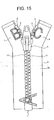
- a desired pattern for example, an alphabet letter
- a desired pattern for example, an alphabet letter
- color is continuously dyed in the fastener tape 6 and the fastener element 11 as illustrated in FIG. 1 and the contour of the pattern or color is formed clearly and neatly, by heat-treating the slide fastener 10 where ink droplets are attached to the fastener tape 6 and the fastener element 11, making it possible to obtain the slide fastener 10 with an enhanced outer appearance.
- the heat treatment is performed by passing the slide fastener 10, for example, through a heated atmosphere, and is also called a dry heat treatment.
- the slide fastener 10 may also be obtained, for example, by ejecting and attaching ink droplets to a continuous fastener stringer 1 which is not yet cut to a predetermined length, subsequently performing a heat treatment on the continuous fastener stringer 1 to dye the continuous fastener stringer 1, then mounting an upper stopper 3, a separable bottom end stop 4, and a slider 5 on a pair of fastener stringers 1, and cutting the fastener stringers 1 by a predetermined length.
- the slide fastener 10 by using a dye ink
- a pigment ink instead of a dye ink.
- the pigment ink is different from a dye ink where dye is dissolved in a solvent, and is a type of ink where pigments are not dissolved in a solvent but are dispersed in the solvent. Even when the slide fastener 10 is colored by using the pigment ink, ink droplets can be stably fixed to the fastener element 11 and the contour of the pattern or color can be shown clearly.
- a color treatment may be performed in the form of a slide fastener 10 and may also be performed in the form of a fastener chain or in the form of a fastener stringer 1.
- slide fastener 10 according to the first embodiment may be dyed through piece-eying instead of being colored by using the above-described inkjet method.
- the fastener chain (or fastener stringer 1) is wound on a dyeing beam to overlap in several layers and is accommodated in a dyeing pot while the fastener chain remains wound on the beam, and the fastener chain is dyed in the dyeing pot.
- the plurality of recesses 13 are formed on the entire first surface 12a of each fastener element 11. Further, it appears that the portions of the first surface 12a where the recesses 13 are not disposed are formed to be planar when viewed by naked eyes, but when observed in an order of micrometer through a microscope and the like, high and low portions are formed in the plane because of the formation of the recesses 13 and the plane has slight height differences.
- the fastener chain can be uniformly and stably dyed to have a desired color without generating color stains in the fastener element 11.
- the first surface 12a of the fastener element 11 may be painted and colored through ejection.
- the fastener element 11 may be plated with a metal, or the fastener stringer 1 may be deposited in a predetermined atmosphere (for example, in an aluminum atmosphere) so that a surface of the fastener element 11 may be surface-treated by forming a film thereon. Further, a surface of the fastener element 11 may be surface-treated by adhering a sheet-shaped film thereto through thermal transfer.
- the slide fastener 10 of the first embodiment is surface-treated, for example, colored through painting, metal plating or deposition as described above, since the plurality of recesses 13 is disposed on the first surface 12a of each fastener element 11 and a fine fixing space having a predetermined capacity is formed in each recess 13, some portion of the paint film or the film enter the fixing space to be fixed with certainty. Accordingly, since an attaching strength between the first surface 12a of the fastener element 11 and the paint film or film formed on the first surface 12a can be remarkably increased, the paint film or film formed on the fastener element 11 cannot be easily peeled off.
- dyeing means that a surface of a resin and an interior near the surface are colored by a dye and painting means that a color is stacked on a surface.
- the fastener tape and the fastener element are made of a material which can be dyed by the same dye.
- the fastener element is made of a polyester resin or a polybutylene terephtalate, and it is preferable that when the material of the fastener tape is a polyamide resin, the fastener element is made of a polyamide resin.
- the slide fastener 10 of the first embodiment is surface-treated by adhering a sheet-shaped film through thermal transfer, since the plurality of recesses 13 is disposed on the first surface 12a of each fastener element 11 and a fine fixing space having a predetermined capacity is formed in each recess 13, an adhesive enters the fixing space to be fixed. Accordingly, since a bonding strength between the first surface 12a of the fastener element 11 and the film adhered onto the first surface 12a can be remarkably increased, the film adhered to the first surface 12a of the fastener element 11 cannot be easily peeled off.
- the recesses 13 are formed only on the first surface 12a of the fastener element 11.
- the invention is not limited thereto, but the semispherical recesses 13 may be formed not on the first surface 12a of the fastener element 11 but only on the second surface 12b on the opposite side thereof, or may be formed on both the first surface 12a and the second surface 12b.
- the fastener tape 6 and an outer surface (first surface 12a) of the fastener element 11 may be colored to have desired shape and color by using an inkjet method, and as illustrated in FIG. 5 , the fastener tape 6 and a rear surface (second surface 12b) of the fastener element 11 may be easily colored to have desired shape (for example, alphabet letter) and color.
- the fastener element 11 has a symmetrical shape on a surface side and a rear surface side of the fastener tape 6
- the fastener element 11 may have different shapes on a surface side and a rear surface side of the fastener tape 6 in the invention.
- a fastener element 21 has different shapes on a surface side and a rear surface side of the fastener tape 6. That is, a half portion (see FIG. 7 ) disposed on a tape surface side of the fastener element 21 has a body 11c, a neck 11b, and a coupling head 11a as in the first embodiment, but a half portion (see FIG.
- the fastener element 21 disposed on a tape rear surface side of the fastener element 21 has a body 21c fixedly attached to the fastener tape 6, and a substantially triangular head 21a installed to extend from the body 21c to an outer side of the fastener tape 6.
- the surfaces of the body 11c, the neck 11b, and the coupling head 11a disposed on the tape surface side form a first surface 22a
- the surfaces of the body 21c and the head 21a disposed on the tape rear surface side form a second surface 22b.
- the plurality of recesses 13 is disposed in zigzag on both the first surface 22a and the second surface 22b of the fastener element 21 according to the modified example, and the recesses 13 disposed on the first and second surfaces 22a and 22b are formed to have a semispherical shape each having the same size.
- the recesses 13 disposed on the first and second surfaces 22a and 22b are disposed at a ratio of one to twenty five recesses 13 per area of 1 mm 2 , and preferably at a ratio of nine to sixteen recesses 13 per area of 1 mm 2 .
- the recesses 13 (except for the recesses 13 having a flaw therein) disposed on the first and second surfaces 22a and 22b have a capacity of 0.002 mm 3 to 0.27 mm 3 and a diameter of 0.05 mm to 0.5 mm. Further, on the first and second surfaces 22a and 22b, the interval between the adjacent recesses 13 is set to 0.05 mm to 0.3 mm.
- the ink droplets ejected onto the first surface 22a of the fastener element 21 may be received by the plurality of semispherical recesses 13 disposed in zigzag and may be stably fixed to the first surface 22a, as in the first embodiment. Further, the ink droplets ejected to the second surface 22b of the fastener element 21 may also be received by the plurality of semispherical recesses 13 disposed in zigzag and stably fixed to the second surface 22b.
- a desired pattern or color is continuously dyed on the front and back surfaces of the fastener tape 6 and the fastener element 21 by heat-treating the slide fastener 20 where ink droplets are attached to the front and back surface of the fastener tape 6 and the fastener element 21, and it is possible to obtain the slide fastener 20 where the contour of the pattern or color thereof is formed clearly and neatly.
- the design of the pattern is not specifically limited, and the pattern includes a pattern having two or more colors.
- the plurality of recesses 13 is formed on the entire first surface 22a and second surface 22b of each fastener element 21 when the above-described fastener chain for the slide fastener 20 according to the modified example is dyed through piece-dyeing, the dye can be smoothly and widely spread on the surface and rear surface of the fastener element 21 when the fastener chain is wound on the beam and is dyed in a dyeing pot. For this reason, the fastener chain can be uniformly and stably dyed to have a desired color without generating color stains in the fastener element 21.
- the attaching strength or bonding strength of the paint film, the coating or the film disposed on the first and second surfaces 22a and 22b can be increased and the paint film, the coating, or the film cannot be easily peeled off from the first and second surfaces 22a and 22b.
- the half portion on the first surface 22a side of the fastener element 21 and the half portion of the second surface 22b side have different shapes, and may give different impressions to a user.
- a recess 13 is formed neither on a second surface 22b side surface (see FIG. 6 ) of the coupling head 11a disposed on the tape surface side nor on a first surface 22a side surface (see FIG. 7 ) of the coupling head 21a disposed on a tape rear surface side. This is for securing strength against the front and back force by allowing the second surface 22b side surface of the coupling head 11a and the first surface 22a side surface of the counterpart coupling head 21a to contact each other on a wider surface when the left and right fastener elements 21 are coupled to each other.
- FIG. 8 is an enlarged perspective view illustrating a fastener element of a slide fastener according to a second embodiment.
- FIG. 9 is a front view of the fastener element
- FIG. 10 is a sectional view of the fastener element.
- a plurality of semispherical bosses 33 is formed on a first surface 32a of each fastener element 31 instead of the plurality of semispherical recesses 13 formed in the above-described fastener element 11 of the first embodiment, and the other configurations are substantially the same as the above-described slide fastener 10 according to the first embodiment.
- the configurations of the plurality of bosses 33 formed on the first surface 32a of each fastener element 31 will be mainly described, and the components and members having the same configurations as the above-described slide fastener 10 of the first embodiment will be provided with the same reference numerals and a description will be omitted.
- the components and members having the same configurations as the above-described slide fastener 10 of the first embodiment will also be provided with the same reference numerals and a description thereof will be omitted.
- a plurality of semispherical bosses 33 having the same shape and size is disposed in zigzag on the substantially entire first surface 32a. Further, if the bosses 33 have similar shapes, the bosses 33 may be formed to have different sizes. Further, the shape of the bosses 33 is not limited to the semispherical shape, but conic shapes or frustum shapes may be employed.
- the bosses 33 formed in each fastener element 31 are disposed at a ratio of one to twenty five bosses 33 per area of 1 mm 2 .
- the bosses are disposed at a ratio of nine embodiment, a space is formed between a plane connecting the apexes of the bosses 33 and the first surface 32a of the fastener element 31 which is flat, by forming the bosses 33 on the first surface 32a.
- the space formed in the second embodiment functions as a fixing space for receiving and fixing ink droplets, for example, when the fastener element 31 is colored through the inkjet method, and functions as a fixing space for circulating a dye and widely spreading the dye on the first surface 32a of the fastener element 31, for example, when the fastener chain is dyed through piece-dyeing.
- the capacity of the fixing space formed for one boss 33 is set to 0.002 mm 3 to 0.27 mm 3 .
- the capacity of the fixing space formed for one boss 33 is, for example, a value obtained by calculating the capacity of the fixing space in a predetermined region and dividing the calculated capacity of the fixing space by the number of bosses 33 disposed in the predetermined region.
- each boss 33 disposed on the first surface 32a is set to 0. 05 mm to 0.5 mm, and the interval between the adjacent bosses 33 is set to 0.05 mm to 0.3 mm.
- the fastener chain for the slide fastener 30 according to the second embodiment is dyed through piece-dyeing, since the fixing space having a predetermined capacity is disposed near the bosses 33 on the first surface 32a of each fastener element 31, the dye can more smoothly and widely spread to the surface or rear surface of the fastener element 31 when the fastener chain is wound on a beam and is dyed in a dyeing pot. For this reason, the fastener chain can be uniformly and stably dyed to have a desired color without generating color stains in the fastener element 31.
- the attaching strength or bonding strength between the first surface 32a and the paint film, the coating, or the film formed on the first surface 32a can be increased and the paint film, the coating, or the film cannot be easily peeled off from the first surface 32a as the fixing space having a predetermined capacity is disposed near the bosses 33 on the first surface 32a of each fastener element 31.
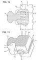
- FIG. 11 is an enlarged perspective view illustrating a fastener element of a slide fastener according to a third embodiment
- FIG. 12 is a front view of the fastener element.
- a plurality of groove-shaped recesses 43 formed in parallel to a widthwise direction of a fastener tape 6 is formed on a first surface 42a of each fastener element 41 instead of the plurality of semispherical recesses 13 formed in the above-described fastener element 11 of the first embodiment.
- the slide fastener 40 according to the third embodiment has substantially the same configuration as the above-described slide fastener 10 according to the first embodiment except that the above-described groove-shaped recesses 43 are formed on the first surface 42a of the fastener element 41.
- each fastener element 41 of the third embodiment the plurality of groove-shaped recesses 43 parallel to the widthwise direction of the fastener tape 6 is disposed at a predetermined interval on substantially the entire first surface 42a.
- each groove-shaped recess 43 has a semicircular cross-section and the groove width of each recess 43 is set to the same size.
- spaces formed in the recesses 43 function as fixing spaces.
- portions between the recesses 43 may be admitted as bosses, and it may be expressed that a plurality of ridge-shaped bosses parallel to the widthwise direction of the fastener tape 6 is disposed on the first surface 42a of the fastener element 41.
- the groove-shaped recesses 43 may be formed to have different sizes.
- the cross-sectional shape of the groove-shaped recesses 43 is not limited to a semicircular shape, but triangular shapes or rectangular shapes may also be employed.
- the groove-shaped recesses 43 disposed in each fastener element 41 are disposed at a ratio of one to twenty five recesses per area of 1 mm 2 . That is, the groove-shaped recesses 43 are disposed at a ratio of one to twenty five recesses in an interval of 1 mm in a lengthwise direction of the fastener tape 6.
- the groove-shaped recesses 43 are disposed at a ratio of three to four recesses per an interval of 1 mm.
- the size of the groove width of each groove-shaped recess 43 is set to 0.05 mm to 0.5 mm, and the interval between the groove-shaped recesses 43 is-set to 0.05 mm to 0.3 mm.
- the fastener tape 6 and the fastener element 41 are colored at a resolution of 180 dpi (dots per 2.54 cm) through an inkjet method
- the ink droplets ejected onto the first surface 42a of the fastener element 41 may be received by the fixing spaces of the plurality of groove-shaped recesses 43 disposed in parallel to the widthwise direction of the fastener tape 6, and the ink droplets may be stably fixed to the first surface 42a of the fastener element 41.
- the adjacent ink droplets attached to the first surface 42a can be effectively prevented from being mixed with each other.
- the fastener chain for the slide fastener 40 according to the third embodiment is dyed through piece-dyeing, the dye can smoothly and widely spread on the surface or rear surface of the fastener element 41 when the fastener chain is wound on the beam and is dyed in a dyeing pot. For this reason, the fastener chain can be uniformmly and stably dyed to have a desired color without generating color stains in the fastener element 41.
- the slide fastener 40 when the first surface 42a of the fastener element 41 is painted and colored through ejection, or the first surface 42a of the fastener element 41 is surface-treated through metal plating or deposition, or surface-treated by adhering a sheet-shaped film through thermal transfer, since the plurality of groove-shaped recesses 43 is formed on the first surface 42a of each fastener element 41, the attaching strength or bonding strength between the first surface 42a and the paint film, the coating, or the film formed on the first surface 42a can be increased and the paint film, the coating, or the film cannot be easily peeled off from the first surface 42a.
- FIG. 13 is an enlarged perspective view illustrating a fastener element of a slide fastener according to a fourth embodiment of the invention.
- a plurality of groove-shaped recesses 53 parallel to a lengthwise direction of the fastener tape 6 is formed on a first surface 52a of each fastener element 51 instead of the plurality of groove-shaped recesses 43 parallel to the widthwise direction of the fastener tape 6 in above-described the fastener element 41 of the third embodiment.
- the slide fastener 50 according to the fourth embodiment has substantially the same configuration as the slide fastener 40 according to the above-described third embodiment except that the groove-shaped recesses 53 are formed in the lengthwise direction of the fastener tape 6.
- each fastener element 51 according to the fourth embodiment the plurality of groove-shaped recesses 53 parallel to the lengthwise direction of the fastener tape 6 is disposed at a predetermined interval on substantially the entire first surface 52a.
- the groove-shaped recesses 53 have a semicircular cross-section, and the grooves width of the recesses 53 are set to the same size.
- the spaces formed in the recesses 53 function as fixing spaces.
- the groove-shaped recesses 53 disposed in each fastener element 51 are disposed at a ratio of one to twenty five recesses per area of 1 mm 2 (that is, at a ratio of one to twenty five recesses in an interval of 1 mm in the widthwise direction of the tape).
- the recesses 53 are disposed at a ratio of three to four recesses.
- the size of the groove width of each groove-shaped recess 53 is set to 0.05 mm to 0.5 mm, and the interval between the groove-shaped recesses 53 is set to 0.05 mm to 0.3 mm.
- the fastener tape 6 and the fastener element 51 are colored at a resolution of 180 dpi (dots per 2.54 cm) through an inkjet method
- the ink droplets ejected onto the first surface 52a of the fastener element 51 may be received by the plurality of groove-shaped recesses 53 disposed parallel to the lengthwise direction of the fastener tape 6, and the ink droplets may be stably fixed to the first surface 52a of the fastener element 51.
- the adjacent ink droplets attached to the first surface 52a can be effectively prevented from being mixed with each other.
- the fastener chain for the slide fastener 50 according to the fourth embodiment is dyed through piece-dyeing, and in regard to the slide fastener 50 when the first surface 52a of the fastener element 51 is painted and colored through ejection, or when the first surface 52a of the fastener element 51 is surface-treated through metal plating or deposition or surface-treated by adhering a sheet-shaped film through thermal transfer, the same effect as in the above-described third embodiment can be obtained.
- the directions where the above-described groove-shaped recesses 43 and 53 are formed are not limited to the directions parallel to the widthwise direction or the lengthwise direction of the fastener tape 6, but the recesses 43 and 53 may also be formed, for example, in a direction inclined at a predetermined angle with respect to the widthwise direction of the fastener tape 6.
- FIG. 14 is an enlarged front view illustrating a fastener element of a slide fastener according to a fifth embodiment of the invention.
- a plurality of square pyramidal recesses 63 is formed on a first surface 62a of each fastener element 61 instead of the plurality of semispherical recesses 13 formed in the above-described fastener element 11 of the first embodiment.
- each fastener element 61 according to the fifth embodiment, the plurality of recesses 63 having a square pyramidal shape of the same size is disposed in zigzag on the first surface 62a.
- the spaces formed in the recesses 63 function as fixing spaces.
- all the recesses 63 formed on the first surface 62a have the same shape and size, and are disposed at a ratio of one to twenty five recesses and preferably at a ratio of nine to sixteen recesses per area of 1 mm 2 . Further, the recesses 63 disposed on the first surface 62a have a capacity of 0.002 mm 3 to 0.27 mm 3 , and the length of one side of the recess 63 on the first surface 62a is set to 0.05 mm to 0.5 mm.
- the plurality of square pyramidal recesses 63 is formed on the first surface 62a of each fastener element 61, and when portions of the first surface 62a where the recesses 63 are not disposed are observed in an order of micrometer through a microscope and the like, the plane has slight height differences.
- the attaching strength or bonding strength of the paint film, the coating, or the film can be increased and the paint film, the coating, or the film cannot be easily peeled off from the first surface 62a as in the above-described first embodiment.
- the fastener tape 6 and the fastener elements 11 to 61 are colored through an inkjet method.
- recesses or bosses having the same shapes (or similar shapes) as the recesses or bosses formed in the fastener elements 11 to 61 may be formed in the same conditions as in the fastener elements 11 to 61, for example, even in the upper stopper 3 or the first surface and/or the second surface of the separable bottom end stop 4.
- the upper stopper 3 or the separable bottom end stop 4 may also be colored through an inkjet method.
- a desired pattern or color are continuously given to the upper stopper 3 or the separable bottom end stop 4 from the fastener tape 6 or the fastener elements 11 to 61, and the contours of the pattern or color can be clearly and neatly formed.
- a continuous pattern for example, an alphabet letter
- color may be neatly and stably given to the fastener tape 6, the fastener element 11, the upper stopper 3, or the separable bottom end stop 4.
- recesses or bosses having the same shapes (or similar shapes) as the recesses or bosses formed in the fastener elements 11 to 61 may be formed in the same conditions as in the fastener elements 11 to 61 even on the first surface and/or the second surface of the slider.
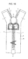
- a slider 8 also called a flat slider in some cases
- a tab is rotatably attached to a side surface of the slider and an upper blade is apt to be exposed to a surface is used.
- a desired pattern for example, an alphabet letter
- a desired pattern or color is continuously given to the slider 8 from the fastener tape 6 or the fastener element 11 and the contour of the pattern or color can be clearly and neatly formed.
- a continuous pattern or color may be neatly and stably given to the fastener tape 6, the fastener element 11, and the slider 8.
- the recesses or bosses on the surface of the fastener element are formed simultaneously when the fastener element is injection-molded or die-cast, but the invention is not limited thereto and the recesses or bosses may be post-processed, for example, after the fastener element is formed.
- a processing of pressing a roller having convexo-concavities on the fastener element or a processing through cutting may be used as the post-processing.
- coating may be performed by applying a synthetic resin on the metallic surface of the fastener element in order to easily fix a coloring material to the fastener element.
- the resin layer formed on the surface of the fastener element does not fill up the fixing spaces of the recesses or bosses on a surface of the fastener element even after coating, the coloring material can be stably fixed to the fixing spaces when the fastener element is colored (dyed) by the coloring material afterward.
- a transparent resin layer as the resin layer formed on a surface of the fastener element, a metal-specific color tone can be given to the colored fastener element.
Landscapes
- Slide Fasteners (AREA)
- Ink Jet (AREA)
Claims (12)
- Verschlussleiste (1), die Folgendes einschließt:ein Verschlussband (6) undmehrere Verschlusselemente (11, 21, 31, 41, 51, 61), die entlang eines Randteils des Verschlussbandes (6) befestigt sind, wobei wenigstens eine Fläche jedes der Verschlusselemente (11, 21, 31, 41, 51, 61) gefärbt oder bemalt ist,dadurch gekennzeichnet, dass Aussparungen (13, 43, 53, 63) oder Vorsprünge (33) in einem Verhältnis von ein bis fünfundzwanzig Aussparungen oder Vorsprünge pro 1 mm2 und mehrere feine Fixierungsräume auf der wenigstens einen Fläche des Verschlusselementes (11, 21, 31, 41, 51, 61), die gefärbt oder bemalt ist, angeordnet sind,
unddie feinen Fixierungsräume durch in den Aussparungen (13, 43, 53, 63) geformte Räume oder zwischen den Vorsprüngen (33) geformte Räume definiert werden. - Verschlussleiste (1) nach Anspruch 1, dadurch gekennzeichnet, dass ein vorbestimmter Abstand zwischen den benachbarten Aussparungen (13, 43, 53, 63) oder den benachbarten Vorsprüngen (33) geformt ist.
- Verschlussleiste (1) nach Anspruch 1 oder 2, dadurch gekennzeichnet, dass die Aussparungen (13, 63) oder die Vorsprünge (33) so geformt sind, dass sie eine halbkugelige Gestalt, eine konische Gestalt oder eine Stumpfgestalt haben.
- Verschlussleiste (1) nach Anspruch 3, dadurch gekennzeichnet, dass ein Fassungsvermögen eines in den Aussparungen (13, 63) oder zwischen den Vorsprüngen (33) geformten Raumes auf zwischen 0,002 mm3 und 0,27 mm3 festgesetzt ist.
- Verschlussleiste (1) nach Anspruch 3, dadurch gekennzeichnet, dass die auf der einen Fläche des Verschlusselements angeordneten mehreren Aussparungen (13, 63) oder Vorsprünge (3) so geformt sind, dass sie die gleiche Form oder ähnliche Formen haben.
- Verschlussleiste (1) nach Anspruch 3, dadurch gekennzeichnet, dass die auf der einen Fläche des Verschlusselements angeordneten mehreren Aussparungen (13, 63) oder Vorsprünge (33) im Zickzack angeordnet sind.
- Verschlussleiste (1) nach Anspruch 1 oder 2, dadurch gekennzeichnet, dass das Verschlusselement (11, 21, 31, 41, 51, 61) durch ein Tintenstrahlverfahren mit Farbe versehen ist.
- Verschlussleiste (1) nach Anspruch 1 oder 2, dadurch gekennzeichnet, dass das Verschlusselement (11, 21, 31, 41, 51, 61) und das Verschlussband (6) so mit Farbe versehen sind, dass sie ein Muster haben.
- Verschlussleiste (1) nach Anspruch 1 oder 2, dadurch gekennzeichnet, dass das Verschlusselement (11, 21, 31, 41, 51, 61) durch Nachfärben mit Farbe versehen ist.
- Verschlussleiste (1) nach Anspruch 1 oder 2, dadurch gekennzeichnet, dass das Verschlusselement (11, 21, 31, 41, 51, 61) einen Körper (11c), der unbeweglich an dem Verschlussband (6) befestigt ist, einen Hals (11b), der sich von dem Körper (11c) zu einer Außenseite des Verschlussbandes (6) erstreckt, und einen Kupplungskopf (11a), der an einem Spitzenende des Halses (11b) angeordnet ist, hat und eine Seitenwandfläche des Körpers (11c), die einer Innenseite des Verschlussbandes (6) gegenüberliegt, so geformt ist, dass sie flach ist.
- Reißverschluss, dadurch gekennzeichnet, dass der Reißverschluss die Verschlussleiste (1) nach einem der Ansprüche 1 bis 10 hat.
- Reißverschluss nach Anspruch 11, dadurch gekennzeichnet, dass in wenigstens einem von einem oberen Anschlag (3) der an einem Ende einer durch die Verschlusselemente (11, 21, 31, 41, 51, 61) gebildeten Elementreihe (2) angeordnet ist, einem unteren Anschlag oder einem abtrennbaren unteren Endanschlag (4), der an einem entgegengesetzten Ende der Elementreihe (2) angeordnet ist, und einem Schieber (5, 8), der entlang der Elementreihe (2) verschiebbar ist, mehrere Aussparungen (13, 43, 53, 63) oder Vorsprünge (33) in einem Verhältnis von ein bis fünfundzwanzig Aussparungen oder Vorsprünge pro 1 mm2 auf einer Fläche, die in die gleiche Richtung zeigt wie eine Fläche, auf der die Aussparungen (13, 43, 53, 63) oder Vorsprünge (33) der Verschlusselemente (11, 21, 31, 41, 51, 61) angeordnet sind, geformt sind.
Applications Claiming Priority (1)
| Application Number | Priority Date | Filing Date | Title |
|---|---|---|---|
| PCT/JP2010/056239 WO2011125176A1 (ja) | 2010-04-06 | 2010-04-06 | ファスナーストリンガー及びスライドファスナー |
Publications (3)
| Publication Number | Publication Date |
|---|---|
| EP2556766A1 EP2556766A1 (de) | 2013-02-13 |
| EP2556766A4 EP2556766A4 (de) | 2014-07-30 |
| EP2556766B1 true EP2556766B1 (de) | 2016-10-12 |
Family
ID=44762163
Family Applications (1)
| Application Number | Title | Priority Date | Filing Date |
|---|---|---|---|
| EP10849420.4A Active EP2556766B1 (de) | 2010-04-06 | 2010-04-06 | Verschlussleiste und reissverschluss |
Country Status (8)
| Country | Link |
|---|---|
| US (1) | US8938863B2 (de) |
| EP (1) | EP2556766B1 (de) |
| JP (1) | JP5583205B2 (de) |
| KR (1) | KR101428900B1 (de) |
| CN (1) | CN102821639B (de) |
| ES (1) | ES2598493T3 (de) |
| TW (1) | TWI500400B (de) |
| WO (1) | WO2011125176A1 (de) |
Families Citing this family (16)
| Publication number | Priority date | Publication date | Assignee | Title |
|---|---|---|---|---|
| ES2644287T3 (es) * | 2010-12-17 | 2017-11-28 | Ykk Corporation | Banda de cierre y cadena de cierre de cremallera, y procedimiento de fabricación de la cadena de cierre de cremallera |
| WO2012164682A1 (ja) * | 2011-05-31 | 2012-12-06 | Ykk株式会社 | 開離嵌挿具付きスライドファスナー及び射出成形用金型 |
| JP5977815B2 (ja) * | 2012-03-30 | 2016-08-24 | Ykk株式会社 | スライドファスナー |
| CN104470399B (zh) * | 2012-05-29 | 2018-01-02 | Ykk株式会社 | 拉链的制造方法以及拉链 |
| WO2014013616A1 (ja) * | 2012-07-20 | 2014-01-23 | Ykk株式会社 | ファスナーストリンガー及びスライドファスナー |
| WO2014199492A1 (ja) * | 2013-06-13 | 2014-12-18 | Ykk株式会社 | ファスナー部品、スライドファスナー及びファスナー部品の製造方法 |
| CN104352033A (zh) * | 2014-11-19 | 2015-02-18 | 江苏汇源拉链制造有限公司 | 新型拉链 |
| KR20160134040A (ko) | 2015-05-14 | 2016-11-23 | 정지옹 | 슬라이드 파스너용 슬라이더 |
| WO2017179213A1 (ja) * | 2016-04-15 | 2017-10-19 | Ykk株式会社 | ファスナーストリンガーの製造方法及びファスナーストリンガー |
| JP2017206789A (ja) * | 2016-05-18 | 2017-11-24 | Ykk株式会社 | 捺染用の前処理剤、捺染用の前処理方法、及び染色方法 |
| CN109312514B (zh) * | 2016-06-10 | 2021-01-22 | Ykk株式会社 | 拉链用带状构件的喷墨装置 |
| CN106333429A (zh) * | 2016-11-01 | 2017-01-18 | 常熟宇威拉链五金配件有限公司 | 一种具有标识能力的拉链 |
| CN109280200B (zh) * | 2017-07-19 | 2022-04-08 | Ykk株式会社 | 一种树脂材料表面形成橡胶层的方法以及使用该方法的拉链,带扣,按扣 |
| IT202100007925A1 (it) * | 2021-03-31 | 2022-10-01 | Ykk Corp | Metodi per la fabbricazione di nastrini di cerniere lampo con denti metallici colorati |
| IT202200018486A1 (it) * | 2022-09-12 | 2024-03-12 | Ykk Corp | Elemento di cerniera lampo con una porzione porta-decorazione |
| USD1088955S1 (en) * | 2023-04-13 | 2025-08-19 | Ykk Corporation | Chain for slide fastener |
Family Cites Families (18)
| Publication number | Priority date | Publication date | Assignee | Title |
|---|---|---|---|---|
| US2041558A (en) | 1934-10-25 | 1936-05-19 | Whitehall Patents Corp | Links of separable fasteners |
| JPS60179004A (ja) | 1984-02-24 | 1985-09-12 | ワイケイケイ株式会社 | スライドフアスナ− |
| JPS62225387A (ja) * | 1986-03-27 | 1987-10-03 | Tohoku Metal Ind Ltd | ポリエステル樹脂表面を備えた被印刷基材を用いた印刷物およびその印刷方法 |
| JPS6420806A (en) * | 1987-07-15 | 1989-01-24 | Yoshida Kogyo Kk | Production of slide fastener having retroreflective function |
| CA2011944C (en) * | 1989-03-16 | 1996-02-20 | Yoshiyuki Horita | Slide fastener and fastener elements therefor |
| JPH07110245B2 (ja) * | 1989-06-09 | 1995-11-29 | ワイケイケイ株式会社 | スライドフアスナー用フアスナーエレメント |
| JP2613802B2 (ja) * | 1989-03-16 | 1997-05-28 | ワイケイケイ 株式会社 | 合成樹脂製スライドファスナー |
| JPH0424004A (ja) * | 1990-05-21 | 1992-01-28 | Daiichi Seni Kako Kk | 模様付きファスナ、その染色方法及び装置 |
| JPH07284404A (ja) * | 1994-04-20 | 1995-10-31 | Ykk Kk | スライドファスナー |
| JPH10313909A (ja) * | 1997-05-19 | 1998-12-02 | Akinori Kubo | スライドファスナ |
| KR200205009Y1 (ko) * | 2000-06-23 | 2000-12-01 | 이윤필 | 다색무늬가 형성된 지퍼 |
| JP2003000307A (ja) * | 2001-06-12 | 2003-01-07 | Young Cheol Kang | 多色カラースライドファスナー及びその製造装置 |
| CN2689755Y (zh) * | 2003-11-10 | 2005-04-06 | 育美拉链有限公司 | 金属拉链的链齿花纹与布带花纹的组成结构 |
| JP2005171448A (ja) * | 2003-12-15 | 2005-06-30 | Yamahiro:Kk | ファスナー |
| US20050217085A1 (en) * | 2004-04-05 | 2005-10-06 | Lu Chi C | Structure of a patterned zipper |
| IL161604A0 (en) * | 2004-04-25 | 2004-09-27 | Artzip Ltd | A zipper |
| JP2006167507A (ja) * | 2004-12-13 | 2006-06-29 | Plascoat Kk | ポリアセタール樹脂成形品への印刷・塗装方法 |
| JP5154294B2 (ja) * | 2008-05-02 | 2013-02-27 | Ykk株式会社 | スライドファスナー |
-
2010
- 2010-04-06 EP EP10849420.4A patent/EP2556766B1/de active Active
- 2010-04-06 ES ES10849420.4T patent/ES2598493T3/es active Active
- 2010-04-06 WO PCT/JP2010/056239 patent/WO2011125176A1/ja not_active Ceased
- 2010-04-06 CN CN201080065864.1A patent/CN102821639B/zh active Active
- 2010-04-06 KR KR1020127026097A patent/KR101428900B1/ko active Active
- 2010-04-06 JP JP2012509225A patent/JP5583205B2/ja active Active
- 2010-04-06 US US13/639,493 patent/US8938863B2/en active Active
- 2010-09-29 TW TW099133105A patent/TWI500400B/zh active
Also Published As
| Publication number | Publication date |
|---|---|
| KR101428900B1 (ko) | 2014-08-08 |
| JPWO2011125176A1 (ja) | 2013-07-08 |
| WO2011125176A1 (ja) | 2011-10-13 |
| US8938863B2 (en) | 2015-01-27 |
| US20130019442A1 (en) | 2013-01-24 |
| KR20120128709A (ko) | 2012-11-27 |
| CN102821639B (zh) | 2015-07-01 |
| EP2556766A4 (de) | 2014-07-30 |
| CN102821639A (zh) | 2012-12-12 |
| TW201134422A (en) | 2011-10-16 |
| EP2556766A1 (de) | 2013-02-13 |
| TWI500400B (zh) | 2015-09-21 |
| JP5583205B2 (ja) | 2014-09-03 |
| ES2598493T3 (es) | 2017-01-27 |
| HK1174509A1 (en) | 2013-06-14 |
Similar Documents
| Publication | Publication Date | Title |
|---|---|---|
| US8938863B2 (en) | Fastener stringer and slide fastener | |
| EP2653050B1 (de) | Verschlussleiste und reissverschlusskette sowie verfahren zur herstellung der reissverschlusskette | |
| CN103826493A (zh) | 拉链的制造方法和拉链 | |
| JP5606548B2 (ja) | ファスナーストリンガー及びスライドファスナー | |
| CN205568061U (zh) | 链带 | |
| JP6211765B2 (ja) | 管状体 | |
| CN103037728B (zh) | 拉链以及拉链的制造方法 | |
| JP2013233458A (ja) | ファスナーストリンガー及びスライドファスナー | |
| TWI624231B (zh) | Zipper chain belt manufacturing method and zipper chain belt | |
| HK1174509B (en) | Fastener stringer and slide fastener | |
| CN113352797A (zh) | 体育用品及图案形成方法 | |
| EP3144156B1 (de) | Aufzeichnungsvorrichtung und aufzeichnungsverfahren | |
| US9522547B1 (en) | Printing system and method therefor | |
| TWM404778U (en) | Nozzle arrangement structure for ink jet seat of object printer |
Legal Events
| Date | Code | Title | Description |
|---|---|---|---|
| PUAI | Public reference made under article 153(3) epc to a published international application that has entered the european phase |
Free format text: ORIGINAL CODE: 0009012 |
|
| 17P | Request for examination filed |
Effective date: 20120926 |
|
| AK | Designated contracting states |
Kind code of ref document: A1 Designated state(s): AT BE BG CH CY CZ DE DK EE ES FI FR GB GR HR HU IE IS IT LI LT LU LV MC MK MT NL NO PL PT RO SE SI SK SM TR |
|
| DAX | Request for extension of the european patent (deleted) | ||
| A4 | Supplementary search report drawn up and despatched |
Effective date: 20140630 |
|
| RIC1 | Information provided on ipc code assigned before grant |
Ipc: A44B 19/06 20060101AFI20140624BHEP Ipc: A44B 19/26 20060101ALI20140624BHEP Ipc: A44B 19/38 20060101ALI20140624BHEP Ipc: A44B 19/36 20060101ALI20140624BHEP |
|
| 17Q | First examination report despatched |
Effective date: 20150731 |
|
| GRAP | Despatch of communication of intention to grant a patent |
Free format text: ORIGINAL CODE: EPIDOSNIGR1 |
|
| INTG | Intention to grant announced |
Effective date: 20160425 |
|
| GRAS | Grant fee paid |
Free format text: ORIGINAL CODE: EPIDOSNIGR3 |
|
| GRAA | (expected) grant |
Free format text: ORIGINAL CODE: 0009210 |
|
| AK | Designated contracting states |
Kind code of ref document: B1 Designated state(s): AT BE BG CH CY CZ DE DK EE ES FI FR GB GR HR HU IE IS IT LI LT LU LV MC MK MT NL NO PL PT RO SE SI SK SM TR |
|
| REG | Reference to a national code |
Ref country code: GB Ref legal event code: FG4D |
|
| REG | Reference to a national code |
Ref country code: CH Ref legal event code: EP |
|
| REG | Reference to a national code |
Ref country code: AT Ref legal event code: REF Ref document number: 835638 Country of ref document: AT Kind code of ref document: T Effective date: 20161015 |
|
| REG | Reference to a national code |
Ref country code: IE Ref legal event code: FG4D |
|
| REG | Reference to a national code |
Ref country code: DE Ref legal event code: R096 Ref document number: 602010037236 Country of ref document: DE |
|
| REG | Reference to a national code |
Ref country code: ES Ref legal event code: FG2A Ref document number: 2598493 Country of ref document: ES Kind code of ref document: T3 Effective date: 20170127 |
|
| REG | Reference to a national code |
Ref country code: LT Ref legal event code: MG4D |
|
| REG | Reference to a national code |
Ref country code: NL Ref legal event code: MP Effective date: 20161012 |
|
| PG25 | Lapsed in a contracting state [announced via postgrant information from national office to epo] |
Ref country code: LV Free format text: LAPSE BECAUSE OF FAILURE TO SUBMIT A TRANSLATION OF THE DESCRIPTION OR TO PAY THE FEE WITHIN THE PRESCRIBED TIME-LIMIT Effective date: 20161012 |
|
| REG | Reference to a national code |
Ref country code: AT Ref legal event code: MK05 Ref document number: 835638 Country of ref document: AT Kind code of ref document: T Effective date: 20161012 |
|
| REG | Reference to a national code |
Ref country code: FR Ref legal event code: PLFP Year of fee payment: 8 |
|
| PG25 | Lapsed in a contracting state [announced via postgrant information from national office to epo] |
Ref country code: GR Free format text: LAPSE BECAUSE OF FAILURE TO SUBMIT A TRANSLATION OF THE DESCRIPTION OR TO PAY THE FEE WITHIN THE PRESCRIBED TIME-LIMIT Effective date: 20170113 Ref country code: SE Free format text: LAPSE BECAUSE OF FAILURE TO SUBMIT A TRANSLATION OF THE DESCRIPTION OR TO PAY THE FEE WITHIN THE PRESCRIBED TIME-LIMIT Effective date: 20161012 Ref country code: NO Free format text: LAPSE BECAUSE OF FAILURE TO SUBMIT A TRANSLATION OF THE DESCRIPTION OR TO PAY THE FEE WITHIN THE PRESCRIBED TIME-LIMIT Effective date: 20170112 Ref country code: LT Free format text: LAPSE BECAUSE OF FAILURE TO SUBMIT A TRANSLATION OF THE DESCRIPTION OR TO PAY THE FEE WITHIN THE PRESCRIBED TIME-LIMIT Effective date: 20161012 |
|
| PG25 | Lapsed in a contracting state [announced via postgrant information from national office to epo] |
Ref country code: IS Free format text: LAPSE BECAUSE OF FAILURE TO SUBMIT A TRANSLATION OF THE DESCRIPTION OR TO PAY THE FEE WITHIN THE PRESCRIBED TIME-LIMIT Effective date: 20170212 Ref country code: NL Free format text: LAPSE BECAUSE OF FAILURE TO SUBMIT A TRANSLATION OF THE DESCRIPTION OR TO PAY THE FEE WITHIN THE PRESCRIBED TIME-LIMIT Effective date: 20161012 Ref country code: BE Free format text: LAPSE BECAUSE OF FAILURE TO SUBMIT A TRANSLATION OF THE DESCRIPTION OR TO PAY THE FEE WITHIN THE PRESCRIBED TIME-LIMIT Effective date: 20161012 Ref country code: AT Free format text: LAPSE BECAUSE OF FAILURE TO SUBMIT A TRANSLATION OF THE DESCRIPTION OR TO PAY THE FEE WITHIN THE PRESCRIBED TIME-LIMIT Effective date: 20161012 Ref country code: HR Free format text: LAPSE BECAUSE OF FAILURE TO SUBMIT A TRANSLATION OF THE DESCRIPTION OR TO PAY THE FEE WITHIN THE PRESCRIBED TIME-LIMIT Effective date: 20161012 Ref country code: FI Free format text: LAPSE BECAUSE OF FAILURE TO SUBMIT A TRANSLATION OF THE DESCRIPTION OR TO PAY THE FEE WITHIN THE PRESCRIBED TIME-LIMIT Effective date: 20161012 Ref country code: PT Free format text: LAPSE BECAUSE OF FAILURE TO SUBMIT A TRANSLATION OF THE DESCRIPTION OR TO PAY THE FEE WITHIN THE PRESCRIBED TIME-LIMIT Effective date: 20170213 Ref country code: PL Free format text: LAPSE BECAUSE OF FAILURE TO SUBMIT A TRANSLATION OF THE DESCRIPTION OR TO PAY THE FEE WITHIN THE PRESCRIBED TIME-LIMIT Effective date: 20161012 |
|
| REG | Reference to a national code |
Ref country code: DE Ref legal event code: R097 Ref document number: 602010037236 Country of ref document: DE |
|
| PG25 | Lapsed in a contracting state [announced via postgrant information from national office to epo] |
Ref country code: EE Free format text: LAPSE BECAUSE OF FAILURE TO SUBMIT A TRANSLATION OF THE DESCRIPTION OR TO PAY THE FEE WITHIN THE PRESCRIBED TIME-LIMIT Effective date: 20161012 Ref country code: CZ Free format text: LAPSE BECAUSE OF FAILURE TO SUBMIT A TRANSLATION OF THE DESCRIPTION OR TO PAY THE FEE WITHIN THE PRESCRIBED TIME-LIMIT Effective date: 20161012 Ref country code: DK Free format text: LAPSE BECAUSE OF FAILURE TO SUBMIT A TRANSLATION OF THE DESCRIPTION OR TO PAY THE FEE WITHIN THE PRESCRIBED TIME-LIMIT Effective date: 20161012 Ref country code: SK Free format text: LAPSE BECAUSE OF FAILURE TO SUBMIT A TRANSLATION OF THE DESCRIPTION OR TO PAY THE FEE WITHIN THE PRESCRIBED TIME-LIMIT Effective date: 20161012 Ref country code: RO Free format text: LAPSE BECAUSE OF FAILURE TO SUBMIT A TRANSLATION OF THE DESCRIPTION OR TO PAY THE FEE WITHIN THE PRESCRIBED TIME-LIMIT Effective date: 20161012 |
|
| PLBE | No opposition filed within time limit |
Free format text: ORIGINAL CODE: 0009261 |
|
| STAA | Information on the status of an ep patent application or granted ep patent |
Free format text: STATUS: NO OPPOSITION FILED WITHIN TIME LIMIT |
|
| PG25 | Lapsed in a contracting state [announced via postgrant information from national office to epo] |
Ref country code: SM Free format text: LAPSE BECAUSE OF FAILURE TO SUBMIT A TRANSLATION OF THE DESCRIPTION OR TO PAY THE FEE WITHIN THE PRESCRIBED TIME-LIMIT Effective date: 20161012 Ref country code: BG Free format text: LAPSE BECAUSE OF FAILURE TO SUBMIT A TRANSLATION OF THE DESCRIPTION OR TO PAY THE FEE WITHIN THE PRESCRIBED TIME-LIMIT Effective date: 20170112 |
|
| 26N | No opposition filed |
Effective date: 20170713 |
|
| PG25 | Lapsed in a contracting state [announced via postgrant information from national office to epo] |
Ref country code: SI Free format text: LAPSE BECAUSE OF FAILURE TO SUBMIT A TRANSLATION OF THE DESCRIPTION OR TO PAY THE FEE WITHIN THE PRESCRIBED TIME-LIMIT Effective date: 20161012 |
|
| REG | Reference to a national code |
Ref country code: CH Ref legal event code: PL |
|
| REG | Reference to a national code |
Ref country code: IE Ref legal event code: MM4A |
|
| PG25 | Lapsed in a contracting state [announced via postgrant information from national office to epo] |
Ref country code: MC Free format text: LAPSE BECAUSE OF FAILURE TO SUBMIT A TRANSLATION OF THE DESCRIPTION OR TO PAY THE FEE WITHIN THE PRESCRIBED TIME-LIMIT Effective date: 20161012 |
|
| PG25 | Lapsed in a contracting state [announced via postgrant information from national office to epo] |
Ref country code: CH Free format text: LAPSE BECAUSE OF NON-PAYMENT OF DUE FEES Effective date: 20170430 Ref country code: LI Free format text: LAPSE BECAUSE OF NON-PAYMENT OF DUE FEES Effective date: 20170430 Ref country code: LU Free format text: LAPSE BECAUSE OF NON-PAYMENT OF DUE FEES Effective date: 20170406 |
|
| REG | Reference to a national code |
Ref country code: FR Ref legal event code: PLFP Year of fee payment: 9 |
|
| PG25 | Lapsed in a contracting state [announced via postgrant information from national office to epo] |
Ref country code: IE Free format text: LAPSE BECAUSE OF NON-PAYMENT OF DUE FEES Effective date: 20170406 |
|
| PG25 | Lapsed in a contracting state [announced via postgrant information from national office to epo] |
Ref country code: MT Free format text: LAPSE BECAUSE OF NON-PAYMENT OF DUE FEES Effective date: 20170406 |
|
| PG25 | Lapsed in a contracting state [announced via postgrant information from national office to epo] |
Ref country code: HU Free format text: LAPSE BECAUSE OF FAILURE TO SUBMIT A TRANSLATION OF THE DESCRIPTION OR TO PAY THE FEE WITHIN THE PRESCRIBED TIME-LIMIT; INVALID AB INITIO Effective date: 20100406 |
|
| PG25 | Lapsed in a contracting state [announced via postgrant information from national office to epo] |
Ref country code: CY Free format text: LAPSE BECAUSE OF NON-PAYMENT OF DUE FEES Effective date: 20161012 |
|
| PG25 | Lapsed in a contracting state [announced via postgrant information from national office to epo] |
Ref country code: MK Free format text: LAPSE BECAUSE OF FAILURE TO SUBMIT A TRANSLATION OF THE DESCRIPTION OR TO PAY THE FEE WITHIN THE PRESCRIBED TIME-LIMIT Effective date: 20161012 |
|
| PGFP | Annual fee paid to national office [announced via postgrant information from national office to epo] |
Ref country code: GB Payment date: 20200325 Year of fee payment: 11 |
|
| PGFP | Annual fee paid to national office [announced via postgrant information from national office to epo] |
Ref country code: FR Payment date: 20200312 Year of fee payment: 11 |
|
| PGFP | Annual fee paid to national office [announced via postgrant information from national office to epo] |
Ref country code: DE Payment date: 20200325 Year of fee payment: 11 Ref country code: ES Payment date: 20200504 Year of fee payment: 11 |
|
| REG | Reference to a national code |
Ref country code: DE Ref legal event code: R119 Ref document number: 602010037236 Country of ref document: DE |
|
| GBPC | Gb: european patent ceased through non-payment of renewal fee |
Effective date: 20210406 |
|
| PG25 | Lapsed in a contracting state [announced via postgrant information from national office to epo] |
Ref country code: FR Free format text: LAPSE BECAUSE OF NON-PAYMENT OF DUE FEES Effective date: 20210430 Ref country code: GB Free format text: LAPSE BECAUSE OF NON-PAYMENT OF DUE FEES Effective date: 20210406 Ref country code: DE Free format text: LAPSE BECAUSE OF NON-PAYMENT OF DUE FEES Effective date: 20211103 |
|
| REG | Reference to a national code |
Ref country code: ES Ref legal event code: FD2A Effective date: 20220630 |
|
| PG25 | Lapsed in a contracting state [announced via postgrant information from national office to epo] |
Ref country code: ES Free format text: LAPSE BECAUSE OF NON-PAYMENT OF DUE FEES Effective date: 20210407 |
|
| P01 | Opt-out of the competence of the unified patent court (upc) registered |
Effective date: 20230428 |
|
| PGFP | Annual fee paid to national office [announced via postgrant information from national office to epo] |
Ref country code: IT Payment date: 20250320 Year of fee payment: 16 |
|
| PGFP | Annual fee paid to national office [announced via postgrant information from national office to epo] |
Ref country code: TR Payment date: 20250321 Year of fee payment: 16 |