EP3144156B1 - Aufzeichnungsvorrichtung und aufzeichnungsverfahren - Google Patents
Aufzeichnungsvorrichtung und aufzeichnungsverfahren Download PDFInfo
- Publication number
- EP3144156B1 EP3144156B1 EP16190329.9A EP16190329A EP3144156B1 EP 3144156 B1 EP3144156 B1 EP 3144156B1 EP 16190329 A EP16190329 A EP 16190329A EP 3144156 B1 EP3144156 B1 EP 3144156B1
- Authority
- EP
- European Patent Office
- Prior art keywords
- recording medium
- liquid
- peeling liquid
- peeling
- recording
- Prior art date
- Legal status (The legal status is an assumption and is not a legal conclusion. Google has not performed a legal analysis and makes no representation as to the accuracy of the status listed.)
- Not-in-force
Links
Images



Classifications
-
- B—PERFORMING OPERATIONS; TRANSPORTING
- B41—PRINTING; LINING MACHINES; TYPEWRITERS; STAMPS
- B41J—TYPEWRITERS; SELECTIVE PRINTING MECHANISMS, i.e. MECHANISMS PRINTING OTHERWISE THAN FROM A FORME; CORRECTION OF TYPOGRAPHICAL ERRORS
- B41J15/00—Devices or arrangements of selective printing mechanisms, e.g. ink-jet printers or thermal printers, specially adapted for supporting or handling copy material in continuous form, e.g. webs
- B41J15/04—Supporting, feeding, or guiding devices; Mountings for web rolls or spindles
-
- B—PERFORMING OPERATIONS; TRANSPORTING
- B41—PRINTING; LINING MACHINES; TYPEWRITERS; STAMPS
- B41J—TYPEWRITERS; SELECTIVE PRINTING MECHANISMS, i.e. MECHANISMS PRINTING OTHERWISE THAN FROM A FORME; CORRECTION OF TYPOGRAPHICAL ERRORS
- B41J15/00—Devices or arrangements of selective printing mechanisms, e.g. ink-jet printers or thermal printers, specially adapted for supporting or handling copy material in continuous form, e.g. webs
- B41J15/04—Supporting, feeding, or guiding devices; Mountings for web rolls or spindles
- B41J15/048—Conveyor belts or like feeding devices
-
- B—PERFORMING OPERATIONS; TRANSPORTING
- B41—PRINTING; LINING MACHINES; TYPEWRITERS; STAMPS
- B41J—TYPEWRITERS; SELECTIVE PRINTING MECHANISMS, i.e. MECHANISMS PRINTING OTHERWISE THAN FROM A FORME; CORRECTION OF TYPOGRAPHICAL ERRORS
- B41J3/00—Typewriters or selective printing or marking mechanisms characterised by the purpose for which they are constructed
- B41J3/407—Typewriters or selective printing or marking mechanisms characterised by the purpose for which they are constructed for marking on special material
- B41J3/4078—Printing on textile
-
- D—TEXTILES; PAPER
- D06—TREATMENT OF TEXTILES OR THE LIKE; LAUNDERING; FLEXIBLE MATERIALS NOT OTHERWISE PROVIDED FOR
- D06P—DYEING OR PRINTING TEXTILES; DYEING LEATHER, FURS OR SOLID MACROMOLECULAR SUBSTANCES IN ANY FORM
- D06P5/00—Other features in dyeing or printing textiles, or dyeing leather, furs, or solid macromolecular substances in any form
- D06P5/30—Ink jet printing
Definitions
- the present invention relates to a recording apparatus and a recording method.
- a recording apparatus that is used has a recording medium affixed to and supported by an adhesive belt for transport, and ink ejected from a recording head to record onto the recording medium.
- Japanese Laid-Open Patent Publication No. H08-302576 discloses an apparatus in which a bonding agent referred to as an adhesive agent is uniformly coated on the top surface of a transport belt.
- JP 2011 006805 relates to an inkjet printing method that uses an inkjet printer having inkjet heads for discharging a bordering liquid, a recording ink and a permeation liquid, respectively.
- the method includes ejecting the bordering liquid onto the bordering part of an image, and ejecting a permeation liquid and a recording liquid onto a ground dyeing part outside of the bordering part of the image.
- the recording liquid forms an image, and the permeation liquid promotes permeation of the recording ink into a cloth.
- US 2008/016630 relates to a method for digitally printing on textile articles comprising a digital application of a dedicated diluent substance according to the type of coloring material used, thereby evenly distributing the volume and concentration of the dyeing substances independently from the intensity of a desired color.
- An apparatus for carrying out the method uses a portion of a printing module that is not involved in the printing of the basic colors C-M-Y-K, for injecting a specific diluent substance selectively integrating the printing, in which the color or dye, because of its low intensity, would be less than the amount necessary for achieving a passing of the coloring substances to the opposite side of the fabric material to be printed upon.
- an objective of the present invention is to prevent the creation of a difference in the adhesive force caused by the difference in the ink ejection volume for the recording medium, and the difficulty in partial peeling when recording to a recording medium affixed to an adhesive belt and then peeling the recording medium from the adhesive belt after recording.
- a recording apparatus as defined in claim 1.
- the peeling solution adhesion unit is configured to eject the peeling liquid from the nozzle array.
- a control unit configured to control operations of the liquid ejection unit and the peeling liquid adhesion unit, in which the control unit is configured to control such that a total volume of liquid that combines a volume of liquid ejected per unit area of the recording medium from the liquid ejection unit and a peeling liquid volume from the peeling liquid adhesion unit becomes a predetermined volume.
- the peeling liquid adhesion unit is configured to adhere the peeling liquid onto the recording medium after the recording medium has been supported by the adhesive belt.
- the peeling liquid adheres to at least a side edge of the recording medium.
- the peeling liquid includes water and a surfactant.
- the recording medium when a liquid for forming an image on a recording medium affixed to an adhesive belt is ejected for recording, and the recording medium is peeled from the adhesive belt after recording, the development of a difference in the adhesive force due to the difference in the volume of liquid ejected onto the recording medium and the difficulty in partially peeling can be prevented.
- Fig. 1 is a schematic side view showing a recording apparatus 1 related to a working example of the present invention.
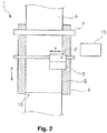
- Fig. 2 is a schematic plan view of the recording apparatus 1 related to a working example of the present invention.
- the recording apparatus 1 in this working example is provided with an adhesive belt 2 that peelably affixes and supports a recording medium P and transports in the transport direction y.
- adhesive belt means a belt in which an adhesive agent is coated on a support surface G of the recording medium P, and the support surface G has adhesiveness for peelably affixing the recording medium P.
- adhesion for peelably affixing the recording medium P is imparted by coating a known coating agent, a so-called “adhesive agent,” onto the support surface G of the recording medium P.
- the adhesive belt 2 is stretched on a drive roller 3 and a following roller 4 that rotate in direction of rotation R.
- the recording apparatus 1 of this working example is provided with the two rollers of the drive roller 3 and the following roller 4, but 3 or more rollers may be provided, and a plurality of these may be drive rollers.
- an adhesion roller 7 is provided at a position opposite the following roller 4.
- the adhesion roller 7 is oriented toward the following roller 4.
- the recording medium P is continuously pressed on and sandwiched between the adhesion roller 7 and the adhesive belt 2 above the following roller 4 to affix to the adhesive belt 2.
- an ejection head 6 provided with a liquid ejection unit 10 that ejects ink as the liquid for forming an image from a nozzle array and a peeling liquid adhesion unit 11 that ejects a peeling liquid D are arranged in the transport path of the recording medium P by the adhesive belt 2.
- the liquid ejection unit 10 of the ejection head 6 comprises nozzle array 10a, nozzle array 10b, nozzle array 10c, and nozzle array 10d that eject each of the colored inks (e.g., yellow (Y), magenta (M), cyan (C), black (K)).
- the peeling liquid adhesion unit 11 is composed of a peeling liquid nozzle array 11a.
- an inkjet recording apparatus is given as this kind of recording apparatus 1.
- the recording medium P is peeled from the adhesive belt 2 at the peeling position 12 that is within a predetermined range on the downstream side of the adhesive belt 2 and is wound by a winding unit 8 rotating in the direction of rotation R via a following roller 9 fixed at a predetermined position.
- the recording medium P is not limited to roll paper; naturally, any medium compatible with the recording apparatus 1 that uses standard paper, cloth or other materials is acceptable.
- downstream is the direction in which the recording medium is transported in the recording apparatus, and the opposite direction thereto is “upstream.”
- inks include colorings and are liquids that are capable of forming images by fixing to the recording medium P.
- the recording apparatus 1 is able to eject inks onto the recording medium from nozzle arrays 10a, 10b, 10c, 10d of the liquid ejection unit 10 to form the desired image while the ejection head 6 moves with reciprocating motion in the direction x that intersects the transport direction y by a carriage 5.
- the peeling liquid D ejected from peeling liquid nozzle array 11a of the peeling liquid adhesion unit 11 can also be affixed to the recording medium P by reciprocating motion of the ejection head 6.
- peeling liquid is a liquid that adheres to the recording medium P supported by the adhesive belt 2 and imparts peelability to the adhesive belt 2.
- the peeling liquid D is preferably a nearly colorless liquid that does not cause chemical changes when mixed with the liquids for forming images (inks in recording apparatus 1) and does not have a visual effect even when adhering to the recording medium P.
- liquids that have water as the main ingredient and contain a surfactant can be used.
- Nonionic surfactants anionic surfactants, amphoteric surfactants are given as the surfactant.
- nonionic surfactants are preferably used.
- known surfactants such as acetylene glycol, acetylene alcohol, ethylene glycol, and polyhydric alcohol can be used as the nonionic surfactant.
- the surfactant contained in the peeling liquid D may include a plurality of surfactants.
- Liquids composed of nearly the same ingredients as ink except for not containing colorings can be used as the peeling liquid D.
- composition of the inks differs depending on the type of recording medium P and, for example, when an image will be formed on cloth, in addition to including water as the solvent and the main component, may include colorings, surfactants, humectants, antiseptic agents, chelating agents, as well as functional additives such as antifoaming agents and the like.
- the peeling liquid adhesion unit 11 that affixes the peeling liquid D to the recording medium P is provided, the volume of ink ejected for the recording medium P differs in each part of the recording medium P when an image is formed from ink. It is possible to adhere the peeling liquid D to parts having small ejection volumes of ink when in a state that has a distribution of parts with a large volume of ejected ink and parts with a small volume.
- liquid is used as the general term for the liquid state as one of the three states of matter.
- the peeling liquid adhesion unit 11 is constituted to eject by a nozzle array similar to the liquid ejection unit that ejects ink.
- the ink and the peeling liquid D can be ejected as droplets and adhere to the recording medium P.
- the liquid ejection unit 10 and the peeling liquid adhesion unit 11 are arranged in the same ejection head 6.
- the configuration is such that after the recording medium P is supported by the adhesive belt 2, the peeling liquid D adheres to the recording medium P on the adhesive belt 2.
- the peeling liquid D adheres to the recording medium P supported by the adhesive belt 2.
- the peeling liquid D can adhere in the same support state as the recording medium when ink ejected by the liquid ejection unit 10 is adhered.
- the recording medium P easily adheres to the adhesive belt 2 before the peeling liquid D adheres.
- each can be arranged in a separate ejection head.
- the ejection head for the peeling liquid adhesion unit 11 is on the transport path due to the adhesive belt 2, and can be arranged either further on the upstream side or the downstream side of the ejection head for the liquid ejection unit 10.
- the peeling liquid D can be adhered in advance to the recording medium P before the recording medium P is supported by the adhesive belt 2.
- the recording apparatus 1 of the working example is provided with an ejection head 6 for recording while in reciprocating motion is provided, but may be a recording apparatus that is provided with a so-called line head equipped with a plurality of nozzles for ejecting ink in a direction that intersects the transport direction y.
- the "line head” is a recording head in which the area of the nozzles formed in the intersecting direction that intersects the transport direction y of the recording medium P is arranged to enable covering the entire intersecting direction of the recording medium P, and one of either the recording head or the recording medium is fixed and the other is moved to form the image.
- the recording apparatus 1 is configured to control the ejection of the ink ejected from the ink nozzle arrays 10a, 10b, 10c, 10d arranged in the ejection head 6 and the peeling liquid D ejected from the peeling liquid nozzle array 11a.
- a control unit 13 controls so that the total volume of liquid - that is, the combined volume of ink ejected from the ink nozzle arrays 10a, 10b, 10c, 10d - and the ejection volume of peeling liquid D ejected from the peeling liquid nozzle array 11a that is ejected per unit area of the recording medium P - to be a predetermined volume.
- the total volume of liquid ejected per unit area in the entire recording medium P "becomes the predetermined volume" and is not restricted to being completely identical volumes at all of the locations on the recording medium P, and means that the adhesive force between the adhesive belt 2 and the recording medium P become nearly equal and includes the range in which a difference is not produced in the ease of peeling.
- Control by the control unit 13 is explained in more detail with reference to Figs. 4A and 4B .
- the recording apparatus 1 forms an image in the region in which ink was ejected (hereinafter, referred to as ⁇ the ink ejection region 14).
- Fig. 4A shows the case in which the density of an image S1 formed on the recording medium P is uniform. Consequently, the ink volume VA1 per unit area is uniform in the entire ink ejection region 14.
- the ink ejection-free region 15 parts outside of the ink ejection region (hereinafter, referred to as the ink ejection-free region 15) do not eject ink. That is, the ink volume VA2 per unit area in the ink ejection-free region 15 is 0.
- peeling liquid D having the same volume as the ink volume VA1 per unit area in the ink ejection region 14 is ejected in the ink ejection-free region 15. Then, the peeling liquid D is not ejected in the ink ejection region 14 (the ejection volume is 0).
- the coating volume of "liquid" on the recording medium P can be uniform over the entire recording medium P.
- Fig. 4B shows the case in which there is grayscale in image S2 formed in the recording medium P.
- Reference number 18 indicates a light color part.
- Reference number 19 indicates a dark color part.
- the grayscale of the image is changed by the ink ejection volume.
- the ink ejection volume of light color part 18 is small.
- the ink ejection volume of dark color part 19 is large.
- the peeling liquid D adheres to the light color part 18 in which the ink ejection volume is low when the peeling liquid D is ejected to the recording medium P in order to correct the difference from the ink ejection volume in the dark color part 19.
- the coating volume of liquid on the recording medium P can be uniform over the entire recording medium P.
- the peeling liquid D preferably adheres to the recording medium P before image formation by the ink.
- a step in which the recording medium P is pressed by the adhesion roller 7 into the adhesive belt 2 and affixed thereto for support is performed, then a step in which the peeling liquid D is ejected and adhered to the recording medium P supported by the adhesive belt 2 (peeling liquid adhesion step) is performed.
- peeling liquid adhesion step the step in which the ink is ejected to form the image.
- the peeling liquid D adheres to the front of the recording medium P, and the ink is able to easily penetrate the recording medium P.
- the peeling liquid adhesion step followed by the image formation step can be performed so that the peeling liquid D is ejected in the outgoing path of the reciprocating motion of the ejection head 6, and ink is ejected during the motion of the return path.
- the width direction of the recording medium P (X direction in Fig. 2 and Figs. 3A and 3B ), it is possible to be in a state in which there is almost no time lag in the adhesion of peeling liquid D and the adhesion of ink, and the penetration states of the liquids in the recording medium P can be more uniform. Namely, it is possible for the adhesive force of the peeling parts to be simultaneously identical at the peeling position 12.
- the peeling liquid adhesion step followed by the image formation step can be performed during the interval when the ejection head 6 moves in the advancing direction.
- the ejection head 6 may be provided with the nozzle arrays 10a, 10b, 10c, 10d that eject each of the colored inks (Y, M, C, K), and the nozzle array 11a and nozzle array 11b that eject the peeling liquid D and are provided at both ends in order to sandwich the nozzle arrays of the colored inks.
- the operations of the peeling liquid adhesion step followed by the image formation step while the ejection head 6 moves in one direction can be in either of the outgoing path and the return path of the reciprocating motion of the ejection head 6.
- the peeling liquid D adheres to at least the side edges 16 of the recording medium P.
- the peeling liquid D is ejected into the region on the side edges 16 from the dotted line 17 in Fig. 4A or Fig. 4B .
- the recording medium P is cloth or paper
- the fibers in the cloth or the paper emerge as a nap.
- the nap of the fibers of the side edges 16 of the recording medium P easily remains sticking to the adhesive belt 2.
- the parts having a small amount of penetration of the "liquid” has stronger adhesive force between the adhesive belt 2 and the recording medium P than parts having a large amount of penetration of the "liquid.”
- the recording apparatus 1 related to a first embodiment of the present invention is provided with an adhesive belt 2 having adhesion to peelably affix the recording medium P, a liquid ejection unit 10 that ejects the liquid for forming an image through nozzle arrays 10a, 10b, 10c, 10d on a recording medium P supported by the adhesive belt 2, and a peeling liquid adhesion unit 11 that adheres a peeling liquid D to the recording medium P.
- the "adhesive belt” means a belt that has an adhesive agent coated on the support surface G of the recording medium P and the support surface G has adhesion to peelably affix the recording medium P.
- the "peeling liquid” adheres to the recording medium P and imparts peelability from the adhesive belt 2 to the recording medium P.
- the peeling liquid adhesion unit 11 for adhering the peeling liquid D to the recording medium P is provided.
- the volume of liquid, for example, ink, for forming the image that is ejected onto the recording medium P differs for each part of the recording medium P and is distributed into parts having a low coating volume of ink and parts having a high coating volume, and the peeling liquid D is adhered to the parts having a low coating volume of ink, and the difference in the volume of "liquid" in the parts having a high coating volume of ink can be made small or eliminated.
- the parts having a low coating volume of ink can be prevented from becoming difficult to peel off.
- the recording apparatus 1 related to a second embodiment of the present invention is the first embodiment in which the peeling liquid adhesion unit 11 has the same structure as the liquid ejection unit 10.
- the peeling liquid adhesion unit 11 has the same structure as the liquid ejection unit 10, and the peeling liquid D can be ejected in the same droplet state as a liquid and adhere to the recording medium P.
- the recording apparatus 1 related to a third embodiment of the present invention is the second embodiment in which a control unit 13 is provided to control the operations of the liquid ejection unit 10 and the peeling liquid adhesion unit 11.
- This control unit 13 controls the ejection volume of liquid from the liquid ejection unit 10 and the ejection volume of peeling liquid D from the peeling liquid adhesion unit 11 to be the same as the total volume of liquid ejected per unit area onto the entire recording medium P.
- the coating volume as a "liquid” that combines the liquid for forming the image and the peeling liquid D can be uniform over the entire recording medium P.
- the penetration state of "liquid" at the interface between the adhesive belt 2 and the recording medium P can be uniform, and concern can be lessened about a difference developing in the adhesive force between the adhesive belt 2 and the recording medium P.
- the difficulty in partially peeling the recording medium P from the adhesive belt 2 can be reduced.
- the "same” total volume of liquid ejected per unit area on the entire recording medium P is not limited to the case of a completely identical volume, and includes the meaning “same” in which the adhesive force between the adhesive belt 2 and the recording medium P may be nearly equal and is within the range in which a substantial difference is not produced in the ease of peeling.
- the recording apparatus 1 related to a fourth embodiment of the present invention is any one of the first embodiment to the third embodiment in which the configuration is such that the peeling liquid D is adhered to the recording medium P after the recording medium P is supported by the adhesive belt 2.
- the adhesion of the peeling liquid D can be in the same support state as the recording medium when the liquid ejected from the liquid ejection unit 10 adheres.
- the recording medium P readily adheres to the adhesive belt 2 before the peeling liquid D is adhered.
- the recording apparatus 1 related to the present invention is the embodiment in which the peeling liquid D adheres to parts outside of the liquid ejection region.
- the difference in the coating volume of "liquid” in the ink ejection region 14 and the ink ejection-free region 15 can be decreased, and the coating volume of "liquid” for the entire recording medium P can be nearly equal.
- the difference in the penetration states of the "liquid" at the interface between the adhesive belt 2 and the recording medium P can be small over the entire recording medium P.
- concern can be lessened about a difference developing in the adhesive force between the adhesive belt 2 and the recording medium P.
- the recording apparatus 1 related to a sixth embodiment of the present invention is any one of the first embodiment to the fifth embodiment in which the peeling liquid D adheres to at least the side edges 16 of the recording medium P.
- the fibers of the cloth or the paper may sometimes form a nap at the side edges 16.
- the nap of fibers at the side edges 16 on this recording medium P easily remains stuck to the adhesive belt 2.
- parts with a low amount of penetration of "liquid" in the recording medium P supported by the adhesive belt 2 has a higher adhesive force between the adhesive belt 2 and the recording medium P than parts having a high amount of penetration of "liquid.”
- the adhesive force in the side edges 16 can be lower.
- the nap of the side edges 16 of the recording medium P can be effectively prevented from remaining on the adhesive belt 2.
- the recording apparatus 1 related to the seventh embodiment of the present invention is any one of the first embodiment to the sixth embodiment in which the peeling liquid D includes water and a surfactant.
- a liquid including water and a surfactant is used as the peeling liquid D and can obtain the same effects as any one of the first embodiment to the sixth embodiment.
- a recording method related to an eighth embodiment of the present invention is provided with a step that adheres the peeling liquid D onto the recording medium P and a step in which a liquid is ejected onto the recording medium P supported by the adhesive belt 2 to form an image, preferably in this order.
Landscapes
- Engineering & Computer Science (AREA)
- Textile Engineering (AREA)
- Ink Jet (AREA)
Claims (7)
- Aufzeichnungsvorrichtung (1), umfassend:ein haftendes Förderband (2), das Adhäsion aufweist, um ein Aufzeichnungsmedium (P) lösbar zu befestigen;eine Flüssigkeitsausstoßeinheit (10), die konfiguriert ist, eine Flüssigkeit, die ein Bild bildet, aus einer Düsenanordnung auf das Aufzeichnungsmedium auszustoßen, das von dem haftenden Förderband getragen wird; undeine Ablöseflüssigkeitsadhäsionseinheit (11), die konfiguriert ist, eine Ablöseflüssigkeit auf das Aufzeichnungsmedium (P) zu heften, dadurch gekennzeichnet, dassdie Ablöseflüssigkeitsadhäsionseinheit (11) konfiguriert ist, die Ablöseflüssigkeit nur auf einen Teil (15, 20) des Aufzeichnungsmediums (P) außerhalb einer Flüssigkeitsausstoßregion (14, 18, 19) zu heften, über der die Flüssigkeitsausstoßeinheit (10) konfiguriert ist, die Flüssigkeit auf das Aufzeichnungsmedium (P) auszustoßen.
- Aufzeichnungsvorrichtung (1) nach Anspruch 1, wobei
die Ablöseflüssigkeitsadhäsionseinheit (11) konfiguriert ist, die Ablöseflüssigkeit aus der Düsenanordnung auszustoßen. - Aufzeichnungsvorrichtung (1) nach Anspruch 2, weiter umfassend
eine Steuereinheit (13), die konfiguriert ist, Operationen der Flüssigkeitsausstoßeinheit (10) und der Ablöseflüssigkeitsadhäsionseinheit (11) zu steuern.
die Steuereinheit (13) konfiguriert ist, so zu steuern, dass ein Gesamtflüssigkeitsvolumen, das ein Volumen von Flüssigkeit, das pro Flächeneinheit des Aufzeichnungsmediums (P) von der Flüssigkeitsausstoßeinheit (10) ausgestoßen wird, und ein Ablöseflüssigkeitsausstoßvolumen von der Ablöseflüssigkeitsadhäsionseinheit (11) ein vorbestimmtes Volumen wird. - Aufzeichnungsvorrichtung (1) nach einem der vorstehenden Ansprüche, wobei
die Ablöseflüssigkeitsadhäsionseinheit (11) konfiguriert ist, die Ablöseflüssigkeit auf das Aufzeichnungsmedium (P) zu heften, nachdem das Aufzeichnungsmedium (P) von dem haftenden Förderband (2) getragen wurde. - Aufzeichnungsvorrichtung (1) nach einem der vorstehenden Ansprüche, wobei
die Ablöseflüssigkeitsadhäsionseinheit (11) konfiguriert ist, die Ablöseflüssigkeit an mindestens einer Seitenkante (16, 17) des Aufzeichnungsmediums (P) anzuheften. - Aufzeichnungsvorrichtung (1) nach einem der vorstehenden Ansprüche, wobei
die Ablöseflüssigkeit Wasser und ein Tensid enthält. - Aufzeichnungsverfahren, umfassend:Anheften einer Ablöseflüssigkeit an ein Aufzeichnungsmedium (P); undAusstoßen einer Flüssigkeit auf das Aufzeichnungsmedium (P), das von einem haftenden Förderband (2) getragen wird, um ein Bild zu bilden, dadurch gekennzeichnet, dass:
der Schritt zum Anheften die Ablöseflüssigkeit nur auf einen Teil (15, 20) des Aufzeichnungsmediums (P) außerhalb einer Flüssigkeitsausstoßregion (14, 18, 19) anheftet, über der die Flüssigkeit auf das Aufzeichnungsmedium (P) in dem Ausstoßschritt ausgestoßen wird.
Applications Claiming Priority (2)
| Application Number | Priority Date | Filing Date | Title |
|---|---|---|---|
| JP2014030801A JP6288430B2 (ja) | 2014-02-20 | 2014-02-20 | 記録装置および記録方法 |
| EP15155868.1A EP2915676B1 (de) | 2014-02-20 | 2015-02-20 | Aufzeichnungsvorrichtung und aufzeichnungsverfahren |
Related Parent Applications (1)
| Application Number | Title | Priority Date | Filing Date |
|---|---|---|---|
| EP15155868.1A Division EP2915676B1 (de) | 2014-02-20 | 2015-02-20 | Aufzeichnungsvorrichtung und aufzeichnungsverfahren |
Publications (3)
| Publication Number | Publication Date |
|---|---|
| EP3144156A2 EP3144156A2 (de) | 2017-03-22 |
| EP3144156A3 EP3144156A3 (de) | 2017-04-19 |
| EP3144156B1 true EP3144156B1 (de) | 2020-04-08 |
Family
ID=52589249
Family Applications (2)
| Application Number | Title | Priority Date | Filing Date |
|---|---|---|---|
| EP15155868.1A Active EP2915676B1 (de) | 2014-02-20 | 2015-02-20 | Aufzeichnungsvorrichtung und aufzeichnungsverfahren |
| EP16190329.9A Not-in-force EP3144156B1 (de) | 2014-02-20 | 2015-02-20 | Aufzeichnungsvorrichtung und aufzeichnungsverfahren |
Family Applications Before (1)
| Application Number | Title | Priority Date | Filing Date |
|---|---|---|---|
| EP15155868.1A Active EP2915676B1 (de) | 2014-02-20 | 2015-02-20 | Aufzeichnungsvorrichtung und aufzeichnungsverfahren |
Country Status (3)
| Country | Link |
|---|---|
| US (1) | US9623686B2 (de) |
| EP (2) | EP2915676B1 (de) |
| JP (1) | JP6288430B2 (de) |
Family Cites Families (15)
| Publication number | Priority date | Publication date | Assignee | Title |
|---|---|---|---|---|
| US5805191A (en) * | 1992-11-25 | 1998-09-08 | Tektronix, Inc. | Intermediate transfer surface application system |
| JP2672767B2 (ja) * | 1993-05-13 | 1997-11-05 | キヤノン株式会社 | プリント方法及び装置及びそのプリント物及び加工品 |
| JP3218274B2 (ja) | 1995-05-09 | 2001-10-15 | カネボウ株式会社 | 捺染方法および装置 |
| KR100641647B1 (ko) * | 2003-03-25 | 2006-11-03 | 주식회사 잉크테크 | 잉크젯 장치를 이용한 원단의 전처리 방법 및 그를 포함하는 잉크젯 날염방법. |
| EP1674275B1 (de) * | 2004-12-22 | 2009-09-30 | Konica Minolta Holdings, Inc. | Tintenstrahldrucker und Druckverfahren unter Verwendung desselben |
| ITMI20061420A1 (it) | 2006-07-20 | 2008-01-21 | J-Teck3 S R L | Metodo ed apparecchiatura per la stampa per la stampa digitale su articoli tessili. |
| KR20080061028A (ko) * | 2006-12-27 | 2008-07-02 | 동부일렉트로닉스 주식회사 | 반도체소자 및 그 제조방법 |
| JP4960814B2 (ja) * | 2007-09-18 | 2012-06-27 | 富士フイルム株式会社 | 画像形成装置および画像形成装置の制御方法 |
| KR100944803B1 (ko) * | 2008-06-26 | 2010-03-02 | (주)에스엠제이 | 스크린 날염기 벨트의 점착제 제거 용제 |
| JP2010106374A (ja) | 2008-10-28 | 2010-05-13 | Konica Minolta Ij Technologies Inc | テキスタイルプリント装置及びテキスタイルプリント方法 |
| JP5381079B2 (ja) | 2008-12-22 | 2014-01-08 | コニカミノルタ株式会社 | テキスタイルプリント方法 |
| JP5444876B2 (ja) * | 2009-06-24 | 2014-03-19 | コニカミノルタ株式会社 | インクジェット捺染方法 |
| JP5817962B2 (ja) * | 2011-03-16 | 2015-11-18 | セイコーエプソン株式会社 | インクジェット捺染装置、および捺染物の製造方法 |
| JP6098432B2 (ja) * | 2013-08-20 | 2017-03-22 | セイコーエプソン株式会社 | インクジェット捺染方法 |
| JP6195062B2 (ja) * | 2013-09-06 | 2017-09-13 | セイコーエプソン株式会社 | 記録装置 |
-
2014
- 2014-02-20 JP JP2014030801A patent/JP6288430B2/ja not_active Expired - Fee Related
-
2015
- 2015-01-21 US US14/601,974 patent/US9623686B2/en not_active Expired - Fee Related
- 2015-02-20 EP EP15155868.1A patent/EP2915676B1/de active Active
- 2015-02-20 EP EP16190329.9A patent/EP3144156B1/de not_active Not-in-force
Non-Patent Citations (1)
| Title |
|---|
| None * |
Also Published As
| Publication number | Publication date |
|---|---|
| EP2915676A1 (de) | 2015-09-09 |
| US9623686B2 (en) | 2017-04-18 |
| EP3144156A3 (de) | 2017-04-19 |
| EP2915676B1 (de) | 2016-10-26 |
| JP6288430B2 (ja) | 2018-03-07 |
| US20150231904A1 (en) | 2015-08-20 |
| JP2015155160A (ja) | 2015-08-27 |
| EP3144156A2 (de) | 2017-03-22 |
Similar Documents
| Publication | Publication Date | Title |
|---|---|---|
| US5485188A (en) | Ink jet recording method employing inks, ink set, and apparatus for use with the inks | |
| JP7494495B2 (ja) | 画像形成装置、画像形成装置の制御方法及び画像形成装置の制御プログラム | |
| JP5532946B2 (ja) | 印刷装置における印刷条件設定方法 | |
| CN104203592A (zh) | 转印膜、转印方法及喷墨记录装置 | |
| MX2014001384A (es) | Impresora de etiqueta sin revestimiento con activacion de pegamento de etiqueta. | |
| EP2915676B1 (de) | Aufzeichnungsvorrichtung und aufzeichnungsverfahren | |
| JP2013103428A (ja) | インクジェット用連続用紙、インクジェットプリンター、およびインクジェットプリンターの予備吐出方法 | |
| JP2000168106A (ja) | インクジェット記録装置の記録処理液吐出検査方法及び該方法に用いる吐出検査フィルム | |
| JP2011067964A (ja) | 液体噴射装置、液体噴射方法 | |
| US12077011B2 (en) | Printing apparatus, printing system and printing method for printing apparatus | |
| JP2011067963A (ja) | 液体噴射装置 | |
| JP2003211641A (ja) | インクジェット記録方法、装置およびインクセット | |
| EP3162582B1 (de) | Druckvorrichtung und verfahren dafür | |
| EP3069885B1 (de) | Aufzeichnungsvorrichtung | |
| EP3069886B1 (de) | Aufzeichnungsvorrichtung | |
| JP2000094661A (ja) | 画像形成装置 | |
| EP3085542B1 (de) | Aufzeichnungsvorrichtung | |
| KR20110127078A (ko) | 잉크젯 날염 방법 및 잉크젯 날염 장치 | |
| US20250108627A1 (en) | Inkjet image forming apparatus | |
| JP5740978B2 (ja) | 液体吐出装置 | |
| JP2003291315A (ja) | インクジェット記録装置及びインクジェット記録方法 | |
| CN120916900A (zh) | 印刷装置、印刷方法及印刷系统 | |
| JP2014237322A (ja) | 液体噴射装置 | |
| JPH02198869A (ja) | インクジェット記録装置 | |
| JP2014144598A (ja) | インクジェットプリンターおよびインクジェットプリンターの制御方法 |
Legal Events
| Date | Code | Title | Description |
|---|---|---|---|
| PUAI | Public reference made under article 153(3) epc to a published international application that has entered the european phase |
Free format text: ORIGINAL CODE: 0009012 |
|
| STAA | Information on the status of an ep patent application or granted ep patent |
Free format text: STATUS: THE APPLICATION HAS BEEN PUBLISHED |
|
| PUAL | Search report despatched |
Free format text: ORIGINAL CODE: 0009013 |
|
| AC | Divisional application: reference to earlier application |
Ref document number: 2915676 Country of ref document: EP Kind code of ref document: P |
|
| AK | Designated contracting states |
Kind code of ref document: A2 Designated state(s): AL AT BE BG CH CY CZ DE DK EE ES FI FR GB GR HR HU IE IS IT LI LT LU LV MC MK MT NL NO PL PT RO RS SE SI SK SM TR |
|
| AK | Designated contracting states |
Kind code of ref document: A3 Designated state(s): AL AT BE BG CH CY CZ DE DK EE ES FI FR GB GR HR HU IE IS IT LI LT LU LV MC MK MT NL NO PL PT RO RS SE SI SK SM TR |
|
| RIC1 | Information provided on ipc code assigned before grant |
Ipc: D06P 5/30 20060101ALI20170313BHEP Ipc: B41J 3/407 20060101ALI20170313BHEP Ipc: B41J 15/04 20060101AFI20170313BHEP |
|
| STAA | Information on the status of an ep patent application or granted ep patent |
Free format text: STATUS: REQUEST FOR EXAMINATION WAS MADE |
|
| 17P | Request for examination filed |
Effective date: 20170911 |
|
| RBV | Designated contracting states (corrected) |
Designated state(s): AL AT BE BG CH CY CZ DE DK EE ES FI FR GB GR HR HU IE IS IT LI LT LU LV MC MK MT NL NO PL PT RO RS SE SI SK SM TR |
|
| GRAP | Despatch of communication of intention to grant a patent |
Free format text: ORIGINAL CODE: EPIDOSNIGR1 |
|
| STAA | Information on the status of an ep patent application or granted ep patent |
Free format text: STATUS: GRANT OF PATENT IS INTENDED |
|
| INTG | Intention to grant announced |
Effective date: 20191209 |
|
| GRAS | Grant fee paid |
Free format text: ORIGINAL CODE: EPIDOSNIGR3 |
|
| GRAA | (expected) grant |
Free format text: ORIGINAL CODE: 0009210 |
|
| STAA | Information on the status of an ep patent application or granted ep patent |
Free format text: STATUS: THE PATENT HAS BEEN GRANTED |
|
| REG | Reference to a national code |
Ref country code: DE Ref legal event code: R081 Ref document number: 602015050566 Country of ref document: DE Owner name: SEIKO EPSON CORPORATION, JP Free format text: FORMER OWNER: SEIKO EPSON CORPORATION, SHINJUKU-KU, TOKYO 163-0811, JP |
|
| AC | Divisional application: reference to earlier application |
Ref document number: 2915676 Country of ref document: EP Kind code of ref document: P |
|
| AK | Designated contracting states |
Kind code of ref document: B1 Designated state(s): AL AT BE BG CH CY CZ DE DK EE ES FI FR GB GR HR HU IE IS IT LI LT LU LV MC MK MT NL NO PL PT RO RS SE SI SK SM TR |
|
| REG | Reference to a national code |
Ref country code: AT Ref legal event code: REF Ref document number: 1253857 Country of ref document: AT Kind code of ref document: T Effective date: 20200415 Ref country code: CH Ref legal event code: EP |
|
| REG | Reference to a national code |
Ref country code: DE Ref legal event code: R096 Ref document number: 602015050566 Country of ref document: DE |
|
| REG | Reference to a national code |
Ref country code: IE Ref legal event code: FG4D |
|
| REG | Reference to a national code |
Ref country code: NL Ref legal event code: MP Effective date: 20200408 |
|
| REG | Reference to a national code |
Ref country code: LT Ref legal event code: MG4D |
|
| PG25 | Lapsed in a contracting state [announced via postgrant information from national office to epo] |
Ref country code: PT Free format text: LAPSE BECAUSE OF FAILURE TO SUBMIT A TRANSLATION OF THE DESCRIPTION OR TO PAY THE FEE WITHIN THE PRESCRIBED TIME-LIMIT Effective date: 20200817 Ref country code: LT Free format text: LAPSE BECAUSE OF FAILURE TO SUBMIT A TRANSLATION OF THE DESCRIPTION OR TO PAY THE FEE WITHIN THE PRESCRIBED TIME-LIMIT Effective date: 20200408 Ref country code: GR Free format text: LAPSE BECAUSE OF FAILURE TO SUBMIT A TRANSLATION OF THE DESCRIPTION OR TO PAY THE FEE WITHIN THE PRESCRIBED TIME-LIMIT Effective date: 20200709 Ref country code: NO Free format text: LAPSE BECAUSE OF FAILURE TO SUBMIT A TRANSLATION OF THE DESCRIPTION OR TO PAY THE FEE WITHIN THE PRESCRIBED TIME-LIMIT Effective date: 20200708 Ref country code: IS Free format text: LAPSE BECAUSE OF FAILURE TO SUBMIT A TRANSLATION OF THE DESCRIPTION OR TO PAY THE FEE WITHIN THE PRESCRIBED TIME-LIMIT Effective date: 20200808 Ref country code: FI Free format text: LAPSE BECAUSE OF FAILURE TO SUBMIT A TRANSLATION OF THE DESCRIPTION OR TO PAY THE FEE WITHIN THE PRESCRIBED TIME-LIMIT Effective date: 20200408 Ref country code: SE Free format text: LAPSE BECAUSE OF FAILURE TO SUBMIT A TRANSLATION OF THE DESCRIPTION OR TO PAY THE FEE WITHIN THE PRESCRIBED TIME-LIMIT Effective date: 20200408 Ref country code: NL Free format text: LAPSE BECAUSE OF FAILURE TO SUBMIT A TRANSLATION OF THE DESCRIPTION OR TO PAY THE FEE WITHIN THE PRESCRIBED TIME-LIMIT Effective date: 20200408 |
|
| REG | Reference to a national code |
Ref country code: AT Ref legal event code: MK05 Ref document number: 1253857 Country of ref document: AT Kind code of ref document: T Effective date: 20200408 |
|
| PG25 | Lapsed in a contracting state [announced via postgrant information from national office to epo] |
Ref country code: HR Free format text: LAPSE BECAUSE OF FAILURE TO SUBMIT A TRANSLATION OF THE DESCRIPTION OR TO PAY THE FEE WITHIN THE PRESCRIBED TIME-LIMIT Effective date: 20200408 Ref country code: BG Free format text: LAPSE BECAUSE OF FAILURE TO SUBMIT A TRANSLATION OF THE DESCRIPTION OR TO PAY THE FEE WITHIN THE PRESCRIBED TIME-LIMIT Effective date: 20200708 Ref country code: RS Free format text: LAPSE BECAUSE OF FAILURE TO SUBMIT A TRANSLATION OF THE DESCRIPTION OR TO PAY THE FEE WITHIN THE PRESCRIBED TIME-LIMIT Effective date: 20200408 Ref country code: LV Free format text: LAPSE BECAUSE OF FAILURE TO SUBMIT A TRANSLATION OF THE DESCRIPTION OR TO PAY THE FEE WITHIN THE PRESCRIBED TIME-LIMIT Effective date: 20200408 |
|
| PG25 | Lapsed in a contracting state [announced via postgrant information from national office to epo] |
Ref country code: AL Free format text: LAPSE BECAUSE OF FAILURE TO SUBMIT A TRANSLATION OF THE DESCRIPTION OR TO PAY THE FEE WITHIN THE PRESCRIBED TIME-LIMIT Effective date: 20200408 |
|
| REG | Reference to a national code |
Ref country code: DE Ref legal event code: R097 Ref document number: 602015050566 Country of ref document: DE |
|
| PG25 | Lapsed in a contracting state [announced via postgrant information from national office to epo] |
Ref country code: ES Free format text: LAPSE BECAUSE OF FAILURE TO SUBMIT A TRANSLATION OF THE DESCRIPTION OR TO PAY THE FEE WITHIN THE PRESCRIBED TIME-LIMIT Effective date: 20200408 Ref country code: DK Free format text: LAPSE BECAUSE OF FAILURE TO SUBMIT A TRANSLATION OF THE DESCRIPTION OR TO PAY THE FEE WITHIN THE PRESCRIBED TIME-LIMIT Effective date: 20200408 Ref country code: AT Free format text: LAPSE BECAUSE OF FAILURE TO SUBMIT A TRANSLATION OF THE DESCRIPTION OR TO PAY THE FEE WITHIN THE PRESCRIBED TIME-LIMIT Effective date: 20200408 Ref country code: SM Free format text: LAPSE BECAUSE OF FAILURE TO SUBMIT A TRANSLATION OF THE DESCRIPTION OR TO PAY THE FEE WITHIN THE PRESCRIBED TIME-LIMIT Effective date: 20200408 Ref country code: EE Free format text: LAPSE BECAUSE OF FAILURE TO SUBMIT A TRANSLATION OF THE DESCRIPTION OR TO PAY THE FEE WITHIN THE PRESCRIBED TIME-LIMIT Effective date: 20200408 Ref country code: CZ Free format text: LAPSE BECAUSE OF FAILURE TO SUBMIT A TRANSLATION OF THE DESCRIPTION OR TO PAY THE FEE WITHIN THE PRESCRIBED TIME-LIMIT Effective date: 20200408 Ref country code: RO Free format text: LAPSE BECAUSE OF FAILURE TO SUBMIT A TRANSLATION OF THE DESCRIPTION OR TO PAY THE FEE WITHIN THE PRESCRIBED TIME-LIMIT Effective date: 20200408 |
|
| PLBE | No opposition filed within time limit |
Free format text: ORIGINAL CODE: 0009261 |
|
| STAA | Information on the status of an ep patent application or granted ep patent |
Free format text: STATUS: NO OPPOSITION FILED WITHIN TIME LIMIT |
|
| PG25 | Lapsed in a contracting state [announced via postgrant information from national office to epo] |
Ref country code: PL Free format text: LAPSE BECAUSE OF FAILURE TO SUBMIT A TRANSLATION OF THE DESCRIPTION OR TO PAY THE FEE WITHIN THE PRESCRIBED TIME-LIMIT Effective date: 20200408 Ref country code: SK Free format text: LAPSE BECAUSE OF FAILURE TO SUBMIT A TRANSLATION OF THE DESCRIPTION OR TO PAY THE FEE WITHIN THE PRESCRIBED TIME-LIMIT Effective date: 20200408 |
|
| 26N | No opposition filed |
Effective date: 20210112 |
|
| PGFP | Annual fee paid to national office [announced via postgrant information from national office to epo] |
Ref country code: IT Payment date: 20210128 Year of fee payment: 7 |
|
| PG25 | Lapsed in a contracting state [announced via postgrant information from national office to epo] |
Ref country code: SI Free format text: LAPSE BECAUSE OF FAILURE TO SUBMIT A TRANSLATION OF THE DESCRIPTION OR TO PAY THE FEE WITHIN THE PRESCRIBED TIME-LIMIT Effective date: 20200408 |
|
| PGFP | Annual fee paid to national office [announced via postgrant information from national office to epo] |
Ref country code: DE Payment date: 20210226 Year of fee payment: 7 Ref country code: GB Payment date: 20210129 Year of fee payment: 7 |
|
| PG25 | Lapsed in a contracting state [announced via postgrant information from national office to epo] |
Ref country code: MC Free format text: LAPSE BECAUSE OF FAILURE TO SUBMIT A TRANSLATION OF THE DESCRIPTION OR TO PAY THE FEE WITHIN THE PRESCRIBED TIME-LIMIT Effective date: 20200408 |
|
| REG | Reference to a national code |
Ref country code: BE Ref legal event code: MM Effective date: 20210228 |
|
| PG25 | Lapsed in a contracting state [announced via postgrant information from national office to epo] |
Ref country code: LI Free format text: LAPSE BECAUSE OF NON-PAYMENT OF DUE FEES Effective date: 20210228 Ref country code: LU Free format text: LAPSE BECAUSE OF NON-PAYMENT OF DUE FEES Effective date: 20210220 Ref country code: CH Free format text: LAPSE BECAUSE OF NON-PAYMENT OF DUE FEES Effective date: 20210228 |
|
| PG25 | Lapsed in a contracting state [announced via postgrant information from national office to epo] |
Ref country code: FR Free format text: LAPSE BECAUSE OF NON-PAYMENT OF DUE FEES Effective date: 20210228 Ref country code: IE Free format text: LAPSE BECAUSE OF NON-PAYMENT OF DUE FEES Effective date: 20210220 |
|
| PG25 | Lapsed in a contracting state [announced via postgrant information from national office to epo] |
Ref country code: BE Free format text: LAPSE BECAUSE OF NON-PAYMENT OF DUE FEES Effective date: 20210228 |
|
| REG | Reference to a national code |
Ref country code: DE Ref legal event code: R119 Ref document number: 602015050566 Country of ref document: DE |
|
| GBPC | Gb: european patent ceased through non-payment of renewal fee |
Effective date: 20220220 |
|
| PG25 | Lapsed in a contracting state [announced via postgrant information from national office to epo] |
Ref country code: GB Free format text: LAPSE BECAUSE OF NON-PAYMENT OF DUE FEES Effective date: 20220220 Ref country code: DE Free format text: LAPSE BECAUSE OF NON-PAYMENT OF DUE FEES Effective date: 20220901 |
|
| PG25 | Lapsed in a contracting state [announced via postgrant information from national office to epo] |
Ref country code: IT Free format text: LAPSE BECAUSE OF NON-PAYMENT OF DUE FEES Effective date: 20220220 Ref country code: HU Free format text: LAPSE BECAUSE OF FAILURE TO SUBMIT A TRANSLATION OF THE DESCRIPTION OR TO PAY THE FEE WITHIN THE PRESCRIBED TIME-LIMIT; INVALID AB INITIO Effective date: 20150220 |
|
| PG25 | Lapsed in a contracting state [announced via postgrant information from national office to epo] |
Ref country code: CY Free format text: LAPSE BECAUSE OF FAILURE TO SUBMIT A TRANSLATION OF THE DESCRIPTION OR TO PAY THE FEE WITHIN THE PRESCRIBED TIME-LIMIT Effective date: 20200408 |
|
| PG25 | Lapsed in a contracting state [announced via postgrant information from national office to epo] |
Ref country code: MK Free format text: LAPSE BECAUSE OF FAILURE TO SUBMIT A TRANSLATION OF THE DESCRIPTION OR TO PAY THE FEE WITHIN THE PRESCRIBED TIME-LIMIT Effective date: 20200408 |
|
| PG25 | Lapsed in a contracting state [announced via postgrant information from national office to epo] |
Ref country code: MT Free format text: LAPSE BECAUSE OF FAILURE TO SUBMIT A TRANSLATION OF THE DESCRIPTION OR TO PAY THE FEE WITHIN THE PRESCRIBED TIME-LIMIT Effective date: 20200408 |
|
| PG25 | Lapsed in a contracting state [announced via postgrant information from national office to epo] |
Ref country code: TR Free format text: LAPSE BECAUSE OF FAILURE TO SUBMIT A TRANSLATION OF THE DESCRIPTION OR TO PAY THE FEE WITHIN THE PRESCRIBED TIME-LIMIT Effective date: 20200408 |