EP2554459A1 - Système d'assemblage d'un composant sur une structure de corps d'un véhicule automobile - Google Patents
Système d'assemblage d'un composant sur une structure de corps d'un véhicule automobile Download PDFInfo
- Publication number
- EP2554459A1 EP2554459A1 EP20110176142 EP11176142A EP2554459A1 EP 2554459 A1 EP2554459 A1 EP 2554459A1 EP 20110176142 EP20110176142 EP 20110176142 EP 11176142 A EP11176142 A EP 11176142A EP 2554459 A1 EP2554459 A1 EP 2554459A1
- Authority
- EP
- European Patent Office
- Prior art keywords
- body structure
- component
- gripping
- welding
- assembly
- Prior art date
- Legal status (The legal status is an assumption and is not a legal conclusion. Google has not performed a legal analysis and makes no representation as to the accuracy of the status listed.)
- Granted
Links
Images


Classifications
-
- B—PERFORMING OPERATIONS; TRANSPORTING
- B23—MACHINE TOOLS; METAL-WORKING NOT OTHERWISE PROVIDED FOR
- B23K—SOLDERING OR UNSOLDERING; WELDING; CLADDING OR PLATING BY SOLDERING OR WELDING; CUTTING BY APPLYING HEAT LOCALLY, e.g. FLAME CUTTING; WORKING BY LASER BEAM
- B23K37/00—Auxiliary devices or processes, not specially adapted to a procedure covered by only one of the preceding main groups
- B23K37/04—Auxiliary devices or processes, not specially adapted to a procedure covered by only one of the preceding main groups for holding or positioning work
- B23K37/0426—Fixtures for other work
-
- B—PERFORMING OPERATIONS; TRANSPORTING
- B23—MACHINE TOOLS; METAL-WORKING NOT OTHERWISE PROVIDED FOR
- B23K—SOLDERING OR UNSOLDERING; WELDING; CLADDING OR PLATING BY SOLDERING OR WELDING; CUTTING BY APPLYING HEAT LOCALLY, e.g. FLAME CUTTING; WORKING BY LASER BEAM
- B23K37/00—Auxiliary devices or processes, not specially adapted to a procedure covered by only one of the preceding main groups
- B23K37/04—Auxiliary devices or processes, not specially adapted to a procedure covered by only one of the preceding main groups for holding or positioning work
- B23K37/0408—Auxiliary devices or processes, not specially adapted to a procedure covered by only one of the preceding main groups for holding or positioning work for planar work
-
- B—PERFORMING OPERATIONS; TRANSPORTING
- B23—MACHINE TOOLS; METAL-WORKING NOT OTHERWISE PROVIDED FOR
- B23K—SOLDERING OR UNSOLDERING; WELDING; CLADDING OR PLATING BY SOLDERING OR WELDING; CUTTING BY APPLYING HEAT LOCALLY, e.g. FLAME CUTTING; WORKING BY LASER BEAM
- B23K37/00—Auxiliary devices or processes, not specially adapted to a procedure covered by only one of the preceding main groups
- B23K37/04—Auxiliary devices or processes, not specially adapted to a procedure covered by only one of the preceding main groups for holding or positioning work
- B23K37/0426—Fixtures for other work
- B23K37/0435—Clamps
- B23K37/0443—Jigs
-
- B—PERFORMING OPERATIONS; TRANSPORTING
- B23—MACHINE TOOLS; METAL-WORKING NOT OTHERWISE PROVIDED FOR
- B23K—SOLDERING OR UNSOLDERING; WELDING; CLADDING OR PLATING BY SOLDERING OR WELDING; CUTTING BY APPLYING HEAT LOCALLY, e.g. FLAME CUTTING; WORKING BY LASER BEAM
- B23K2101/00—Articles made by soldering, welding or cutting
- B23K2101/006—Vehicles
-
- Y—GENERAL TAGGING OF NEW TECHNOLOGICAL DEVELOPMENTS; GENERAL TAGGING OF CROSS-SECTIONAL TECHNOLOGIES SPANNING OVER SEVERAL SECTIONS OF THE IPC; TECHNICAL SUBJECTS COVERED BY FORMER USPC CROSS-REFERENCE ART COLLECTIONS [XRACs] AND DIGESTS
- Y10—TECHNICAL SUBJECTS COVERED BY FORMER USPC
- Y10T—TECHNICAL SUBJECTS COVERED BY FORMER US CLASSIFICATION
- Y10T29/00—Metal working
- Y10T29/49—Method of mechanical manufacture
- Y10T29/49616—Structural member making
- Y10T29/49622—Vehicular structural member making
-
- Y—GENERAL TAGGING OF NEW TECHNOLOGICAL DEVELOPMENTS; GENERAL TAGGING OF CROSS-SECTIONAL TECHNOLOGIES SPANNING OVER SEVERAL SECTIONS OF THE IPC; TECHNICAL SUBJECTS COVERED BY FORMER USPC CROSS-REFERENCE ART COLLECTIONS [XRACs] AND DIGESTS
- Y10—TECHNICAL SUBJECTS COVERED BY FORMER USPC
- Y10T—TECHNICAL SUBJECTS COVERED BY FORMER US CLASSIFICATION
- Y10T29/00—Metal working
- Y10T29/49—Method of mechanical manufacture
- Y10T29/49826—Assembling or joining
- Y10T29/49828—Progressively advancing of work assembly station or assembled portion of work
-
- Y—GENERAL TAGGING OF NEW TECHNOLOGICAL DEVELOPMENTS; GENERAL TAGGING OF CROSS-SECTIONAL TECHNOLOGIES SPANNING OVER SEVERAL SECTIONS OF THE IPC; TECHNICAL SUBJECTS COVERED BY FORMER USPC CROSS-REFERENCE ART COLLECTIONS [XRACs] AND DIGESTS
- Y10—TECHNICAL SUBJECTS COVERED BY FORMER USPC
- Y10T—TECHNICAL SUBJECTS COVERED BY FORMER US CLASSIFICATION
- Y10T29/00—Metal working
- Y10T29/53—Means to assemble or disassemble
- Y10T29/534—Multiple station assembly or disassembly apparatus
- Y10T29/53417—Means to fasten work parts together
Definitions
- the present invention relates to a system for assembly of a component on a motor-vehicle body structure, of the type comprising:
- body structure a body of a motor vehicle or any subassembly thereof, such as for example a chassis.
- the object of the present invention is to provide an assembly system that will enable carrying-out of a process of assembly characterized by shorter cycle times with a structure that is simple and of contained cost.
- a further object of the present invention is to provide an assembly system capable of operating on different models of motor vehicle.
- One or more of said targets are achieved via an assembly system having the characteristics of Claim 1.
- the subject of the present invention is also a method of assembly according to Claim 9.
- the system described herein is characterized in that the clamping device is provided with means for gripping said component and in that it comprises first manipulator means for bringing said device into a condition of connection with said component in a pick-up position, according to a predetermined mutual positioning, and for carrying said device connected to said component to a body structure that is located in a position, on said conveying line, upstream of said welding centre, in order to constrain it to said body structure according to a mutual positioning, whereby said component comes to occupy said proper position of assembly.
- the assembly system described herein is configured for positioning the component in its correct position of assembly with respect to the body structure, already in a position upstream of the welding centre, in such a way that in said centre only welding of the component is to be performed and not also its positioning. As will be seen in what follows, this enables reduction of the cycle times of the system, since the times for positioning the component are comprised within a separate cycle, carried out upstream of the welding centre.
- the aforesaid gripping and clamping device once it has been connected to the component and has been constrained to the body structure, is conveyed together with the latter from the conveying line up to the welding centre.
- the system comprises second manipulator means designed to remove the device from the body structure, after completion of the operations of welding of the component on said structure.
- said device is prearranged for being supported by the body structure itself.
- the system comprises a storage site, onto which the gripping and clamping device is released after use and which is prearranged for interfacing with the aforesaid first and second manipulator means.
- the first manipulator means are designed to pick up the device from said storage site, for assembly of a new component, whereas the aforesaid second manipulator means are designed to release the device onto said site at the end of the operations of welding of said component.
- the storage site comprises a structure that extends along the conveying line of the system and is such as to interface, on its side upstream (with respect to the direction of advance of the body structures along the conveying line), with the aforesaid first manipulator means, and, on its side downstream (with respect to the direction of advance of the body structures along the conveying line), with the aforesaid second manipulator means.
- the storage site comprises means for conveying the device between the two sides referred to above, upstream and downstream.
- a closed path of the aforesaid gripping and clamping device is determined, which comprises:
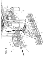
- the reference number 10 designates a system for assembly of a roof panel P (in the figures some of these are designated by P I , P II , P III , P IV ) on a motor-vehicle body structure.
- said system comprises: a welding centre 4, where welding of the roof panel on the body structure is carried out; and a conveying line 2 for carrying a succession of body structures to the welding centre and carrying out of said welding centre said structures with the roof panel assembled thereon.
- a welding centre 4 where welding of the roof panel on the body structure is carried out
- a conveying line 2 for carrying a succession of body structures to the welding centre and carrying out of said welding centre said structures with the roof panel assembled thereon.
- the body structure designated as a whole by the reference number 3 (in the figures a number of body structures are represented, designated by 3A, 3B, 3C) is constituted by a plurality of elements of pressed sheet metal.
- the body structure comprises a bottom portion of chassis 3 I , two opposite side panels 3 II , and, at the top, cross members 3 III for connecting the two side panels.
- a compartment 3 IV for housing the roof panel on the body structure is identified by the two side panels 3 II , in its transverse direction, and by the two cross members 3 III , in its longitudinal direction.
- Assembly of the roof panel on the body structure envisages first positioning of the roof panel in the compartment, and, subsequently, its connection, via welding, both on the side panels and on the cross members of the body structure.
- the roof panel is connected to the side panels via brazing, and to the cross members via spot welding.
- the conveying line 2 can be built in any one of various known ways.
- the example illustrated in the drawings regards the case of a line with a plurality of motor-driven rollers, governed, in a way in itself known, by one or more motors and corresponding transmissions (not visible in the drawings).
- the structure of each body rests on a pallet 2', which is provided with supports on which the body structure rests according to a precise and predetermined positioning.
- the welding centre 4 is prearranged for receiving the body structure and clamping it in a predetermined position via referencing and clamping members (not visible in the drawings) provided within the welding centre.
- the type of said members can vary according to the conveying means used on the conveying line of the system.
- the welding operations have been divided between two successive stations: in the first station, designated in the figures by the reference number 40, the connection of the roof panel to the side panels is carried out via brazing, whilst in the second station, designated in the figures by the reference number 40', the connection of the roof panel to the cross members is performed via spot welding.
- the first station comprises two robots 42, set on either side of the conveying line 2 and each designed to operate on the longitudinal side of the roof panel corresponding thereto.
- Said robots are designed to carry out operations of brazing and can present any configuration of a known type that may be suitable for said purpose.
- the second station comprises, instead, two robots 42', set on one and the same side of the conveying line 2, at a distance from one another along the same conveying line, and each designed to carry out welding of the roof panel to the cross member 3 III closest to it.
- the roof panel is referenced and clamped in the proper position of assembly on the body structure before this is brought into the welding centre.
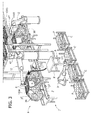
- said system comprises, on the conveying line 2, a station 6 for fitting the roof panel on the body structure (which, to all effects, can simply be a position on the conveying line 2 on which parking of the body structures is envisaged), which is located upstream of the welding centre with respect to the direction of advance of the body structures along the conveying line 2.
- said system comprises a loading station 8, where the roof panel to be assembled is loaded, said roof panel being carried via a robot 9 designed to pick up the roof panel from one of the containers C, C' set at the side of said loading station.
- the loading station 8 can be of any known type and substantially has the sole purpose of defining, as will be seen in what follows, a position for picking up the component.
- the loading station 8 comprises a platform 8' that defines at the top a resting surface on which the roof panel is set.
- a resting surface on which the roof panel is set.
- means (not illustrated) designed to constitute a reference for positioning the roof panel on said resting surface in a precise and predetermined way.
- the assembly system further comprises a device 100 (illustrated in the figures are various units of said device, some of which are designated by 100A, 100B, 100C, 100D), designed to clamp the roof panel in the proper position of assembly on the body structure. Illustrated in the figures is an example of said device, which will, however, be described in greater detail hereinafter.
- the system comprises first means 12, which in the example illustrated are represented by a manipulator robot with six degrees of freedom, designed to carry the device into the loading station 8, where the roof panel has previously been loaded, and to set the device in a condition of mutual connection with said roof panel.
- the device is set in a predetermined relative position with respect to the roof panel, and is connected thereto so that they will both be displaceable, fixed with respect to one another.
- the first means are designed to carry the device, and the roof panel connected thereto, to a body structure that is located in the aforesaid fitting station.
- the device is constrained to the body structure according to a mutual positioning whereby the roof panel comes to occupy the proper position of assembly, in the compartment 3 IV defined at the top by the body structure itself. Consequently, by means of the device, the roof panel comes to occupy, clamped on the body structure, the correct position of assembly and can now displace therewith as far as the welding centre.
- said first means are provided with sensor devices designed to detect the position of the roof panel with respect to that of the compartment in which it is housed in the body structure, and the control unit of said first means is designed to guide the operations of positioning of the roof panel according to the information received from said sensor devices.
- Said sensor devices can, for example, comprise a video camera or else "mechanical" members, such as for example feeler elements. The same sensor devices, or similar sensor devices, can be used for carrying out proper positioning of the device 100 on the roof panel.
- the clamping device has means for connecting the roof panel to itself in a temporary way.
- Said means can, for example, envisage suction elements or else magnetic elements, such as for example electromagnets.
- the clamping device is prearranged for being supported by the body structure itself.
- the weight of the device must be such as not to subject the body structure to any significant deformation in so far as there would otherwise arise the risk of jeopardizing proper assembly of the roof panel.
- the device can, instead, envisage that the device be prearranged for unloading, at least partially, its weight directly or indirectly on the pallet 2' (or on any other means having the function of conveying the car-body structures along the conveying line 2), so as to lighten or even eliminate the weight weighing on the body structure.
- the pallet can present corresponding supporting formations, prearranged for taking up and supporting said device.
- the device is totally supported by the body structure or whether appropriate supports are instead provided on the pallet, as mentioned above, once the device is constrained to the body structure, said device, and the roof panel connected thereto, can be moved together with the body structure, and along with said structure can advance, by means of the conveying line 2, from the fitting station up to the welding centre.
- the roof panel consequently arrives in the welding centre already in the correct position of assembly, and, as will be seen in what follows, as soon as the pallet 2' is clamped in position the welding operations can immediately start.
- the means via which the device is gripped to the body structure can be of any known type in the context here of interest and are not consequently described in detail.
- the system comprises second means 14 - in the figures represented by a manipulator robot with six degrees of freedom - designed to pick up the clamping device from the body structure, as soon as the operations of welding on the roof panel are terminated.
- said second means are set in the second welding station 40'.
- the structure of the second means 14, as likewise their control architecture, are not described in detail herein in so far as they can be built in any way known to the person skilled in the art and their specific configurations in themselves are not important with respect to the innovations introduced by the system described herein.
- the device for clamping the roof panel is able, whilst it keeps the roof panel in the proper position of assembly on the body structure, to travel at the same time together with said structure.
- Said device hence enables displacement of the body structure between the two welding stations without any loss of the geometry of the roof panel in the passage from one station to the next. Without such a clamping device, which is mobile together with the structure, displacement of the body structure between the two successive welding stations would necessarily require, instead, removal of the device between one welding step and another, with the consequent loss of the geometry of the roof panel.
- the two stations of the welding centre are characterized by the low number of robots and tools, and are hence constructively simpler and easier to manage as compared to a single station for both of the welding steps.
- the system comprises a storage site, which is prearranged for interfacing with the aforesaid first and second means and is designed to receive the clamping device 100.
- the first means are designed to pick up the device from said storage site in order to fit a new roof panel on the body structure, whereas the aforesaid second means are designed to release the device on said site after having removed it from the body structure.
- the storage site has an overhead structure 16, which is set above the welding centre.
- Said overhead structure interfaces, on a first side 16' thereof, the one set upstream with respect to the direction of advance of the body structures, with the aforesaid first means, and on its opposite side 16", the one set downstream with respect to the direction of advance of the body structures, with the aforesaid second means.
- the first means are designed to pick up the device from the side upstream of the storage site, whereas the second means are designed to release the device on the side downstream of said site.
- said storage site comprises means for conveying up to the side upstream the device that has been released on the side downstream by the second means so that said device will be again picked up by the first means of the system for assembly of a new roof panel.
- said means comprise a conveyor 16a, which is carried by the overhead structure 16 and extends in a direction substantially parallel to the direction of advance of the conveying line 2.
- the system comprises a number of units of the clamping device 100, in order to guarantee a greater productivity of the system.
- the number of said units is four.
- Figure 1 illustrates an instant of an operating cycle of the system.
- three body structures 3A, 3B and 3C are set in the three successive stations 6, 40, 40', respectively, of the assembly system: the first body structure 3A is located in the fitting station 6, the second body structure 3B in the first welding station 40, and the third body structure 3C in the second welding station 40'.
- the system envisages four clamping devices:
- the first device 100A is picked up by the first means 12 from the storage site 16 and is taken into the loading station 6 to be connected to the first roof panel P I , which has been previously loaded onto said station via the robot 9. Said first means then carry the first device 100A with the first roof panel connected thereto to the first body structure 3A, and said first device is then clamped on said body structure so that the first roof panel comes to occupy, with respect to the first body structure, the correct position of assembly.
- the welding robots 42 make the lateral seam welds for connecting the second roof panel P II to the second body structure 3B, whilst said roof panel is kept in the correct position of assembly by the second device 100B.
- the welding robots make the welds for connecting the third roof panel P III to the cross members of the third body structure 3C, whilst said roof panel is kept in the correct position of assembly by the third device 100C, and, once said welding operation is through, the second means 14 remove said device from the body structure and release it on the side downstream 16" of the storage site.
- the fourth clamping device 100D which has been released in a preceding cycle on the side downstream 16" of the storage site, is now conveyed up to the side upstream 16' of said site.
- the first body structure 3A goes into the first welding station 40, the second body structure 3B into the second welding station 40', the third body structure 3C exits from the assembly system, whilst the fourth body structure is brought into the fitting station 6.
- the fourth roof panel is positioned, via the fourth device, in the proper position of assembly on the fourth body structure, whilst the first and second roof panels undergo welding, respectively, in the welding stations 40 and 40'.
- the operating cycles then follow one another in the way referred to above, for all the roof panels to be assembled.
- the system is of course prearranged for being controlled automatically by means of an electronic control unit, according to a technique in itself known, which activates the various component parts of the system automatically in order to obtain the desired operating cycle.
- each clamping device comprising:
- the system envisages, for each operating cycle, in addition to the clamping devices that, in the cycle in progress, are located in the fitting station and in the welding centre, a further clamping device to be made immediately available for the next cycle.
- said system moreover envisages a storage site on which the clamping device currently not being used is set waiting to be picked up by the first means, being carried there by the second means at the end of a previous cycle.
- the system is configured so as to be able to operate on different models of motor vehicle.
- the system comprises for each model of motor vehicle at least one container of roof panels, and, in the same way, the storage site is divided into a number of sectors corresponding to the number of different models, each sector interfacing with the first and second means of the system and presenting means for conveying the individual devices from the second means to the first means.
- the figures represent a system prearranged for assembling four different models; the system comprises, in fact, four containers, each designed to provide the roof panels of a respective model, and in the same way the overhead structure comprises four conveyors 16a, which run parallel to one another, each connecting the side downstream 16" to the side upstream 16', and are each designed to receive the devices for the roof panels of a respective model.
- the specific model to be assembled via the robot 9, from one of the containers the corresponding roof panel is picked up, and, via the first means 12, from the storage site the device 100 for said roof panel is picked up.
- Figure 1 illustrates assembly of a model of motor vehicle for which the roof panels P I , P II , P III , P IV of the container C' are used, as well as the clamping devices 100A, 100B, 100C and 100D, which, during operation, are released on the first belt conveyor 16a.
- the system envisages four clamping devices, which are located all on the storage site - on the conveyor as illustrated in Figure 1 or else in an area of the site purposely equipped to receive said devices - when the assembly of another model is in progress.
- the assembly system described herein can thus be rendered flexible and capable of operating on a number of models of motor vehicle, albeit maintaining the same configuration that has been described previously. It should on the other hand be noted how passage from one model to another does not require any additional operation (and hence additional time) with respect to the normal operating process of the system.
- the referencing and clamping device is prearranged for being supported by the body structure itself.
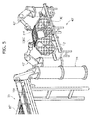
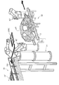
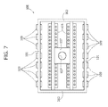
- Figure 5 illustrates an example of such a device.
- the device comprises a framework having a generic framed load-bearing structure, defined by two longitudinal bars 101 connected together, at the ends, by two transverse bars 103.
- two attachment portions 105 Suspended from said frame are two attachment portions 105 provided with suction pads, for connection of the device to the roof panel, which extend in the longitudinal direction of the frame and are set substantially symmetrical to one another with respect to an axis of longitudinal symmetry of the frame itself.
- said attachment portions are shifted towards the centre of the frame and set at a distance from the longitudinal bars 101 in order to leave between each of them and the corresponding bar a space through which the welding head of the robot can operate on the corresponding longitudinal edge of the roof panel.
- the frame is such as to enable the welding head of the robot to operate on the front and rear portions of the roof panel.
- An attachment plate 107 for gripping the device by the aforesaid first and second means is fixed to the frame in a central position with respect to a plan view of the frame, and has an opening 107' designed to be engaged by corresponding gripping means of the aforesaid first and second means.
- the frame-like structure of said device is prearranged for being fitted on the body structure by being lowered from above and rested on the side panels of said structure, in a position corresponding to its longitudinal bars.
- each of said bars can envisage a row of blocks 109 projecting downwards, with respect to the condition of use of the device, which are designed to engage the top profile of said side panels.
- said device further comprises clamping members (not illustrated) that are actuated once the device has been laid on the body structure so as to clamp it thereon and prevent any movement thereof with respect to the structure itself.
- said members can be of any known type and are consequently not described herein.
- the structure of the clamping device 100 may, however, also be different from the one described and illustrated herein; for example, as already mentioned previously, the device can be prearranged for resting on supports carried by the pallet and for said purpose present a spider-like structure, provided with feet designed to rest on said supports.
- the body structure when entering the assembly system, to present side panels free to perform minor oscillations with respect to the bottom panel about an axis parallel to the direction of advance of the body structure along the conveying line.
- the device and the roof panel are found to oscillate together with the body structure itself once they are constrained thereto.
- guide means that act on the device whilst the body structure advances within the welding centre in order to reference it in position with respect to the bottom panel and then keep it in position during the welding operation so as to reference also the side panels of the body structure and hold them in position.
Landscapes
- Physics & Mathematics (AREA)
- Optics & Photonics (AREA)
- Engineering & Computer Science (AREA)
- Mechanical Engineering (AREA)
- Automobile Manufacture Line, Endless Track Vehicle, Trailer (AREA)
- Automatic Assembly (AREA)
Priority Applications (12)
| Application Number | Priority Date | Filing Date | Title |
|---|---|---|---|
| ES11176142.5T ES2605434T3 (es) | 2011-08-01 | 2011-08-01 | Sistema para montar un componente sobre una estructura de carrocería de un vehículo de motor |
| EP11176142.5A EP2554459B1 (fr) | 2011-08-01 | 2011-08-01 | Système d'assemblage d'un composant sur une structure de corps d'un véhicule automobile |
| SI201131023A SI2554459T1 (sl) | 2011-08-01 | 2011-08-01 | Sistem za sestavljanje komponent na karoseriji motornega vozila |
| RS20161139A RS55439B1 (sr) | 2011-08-01 | 2011-08-01 | Sistem za sklapanje komponente na strukturu tela motornog vozila |
| PL11176142T PL2554459T3 (pl) | 2011-08-01 | 2011-08-01 | System montażu części składowej na konstrukcji nadwozia pojazdu samochodowego |
| CA2771737A CA2771737C (fr) | 2011-08-01 | 2012-03-19 | Systeme d'asssemblage d'une composante de structure de chassis de vehicule a moteur |
| MX2012003667A MX2012003667A (es) | 2011-08-01 | 2012-03-27 | Sistema para ensamblar un componente en una estructura de carroceria de automovil. |
| US13/473,689 US8950647B2 (en) | 2011-08-01 | 2012-05-17 | System for assembly of a component on a motor-vehicle body structure |
| RU2012125247/11A RU2591106C2 (ru) | 2011-08-01 | 2012-06-18 | Система для сборки компонента на каркасе кузова автомобиля |
| BR102012016400A BR102012016400A2 (pt) | 2011-08-01 | 2012-07-02 | Sistema para montagem de um componente em uma estrutura de chassi de veículo a motor |
| CN201210270110.0A CN102909500B (zh) | 2011-08-01 | 2012-08-01 | 用于将构件组装在机动车辆车体结构上的系统 |
| US14/588,486 US9278410B2 (en) | 2011-08-01 | 2015-01-02 | System for assembly of a component on a motor-vehicle body structure |
Applications Claiming Priority (1)
| Application Number | Priority Date | Filing Date | Title |
|---|---|---|---|
| EP11176142.5A EP2554459B1 (fr) | 2011-08-01 | 2011-08-01 | Système d'assemblage d'un composant sur une structure de corps d'un véhicule automobile |
Publications (2)
| Publication Number | Publication Date |
|---|---|
| EP2554459A1 true EP2554459A1 (fr) | 2013-02-06 |
| EP2554459B1 EP2554459B1 (fr) | 2016-09-28 |
Family
ID=45375146
Family Applications (1)
| Application Number | Title | Priority Date | Filing Date |
|---|---|---|---|
| EP11176142.5A Not-in-force EP2554459B1 (fr) | 2011-08-01 | 2011-08-01 | Système d'assemblage d'un composant sur une structure de corps d'un véhicule automobile |
Country Status (11)
| Country | Link |
|---|---|
| US (2) | US8950647B2 (fr) |
| EP (1) | EP2554459B1 (fr) |
| CN (1) | CN102909500B (fr) |
| BR (1) | BR102012016400A2 (fr) |
| CA (1) | CA2771737C (fr) |
| ES (1) | ES2605434T3 (fr) |
| MX (1) | MX2012003667A (fr) |
| PL (1) | PL2554459T3 (fr) |
| RS (1) | RS55439B1 (fr) |
| RU (1) | RU2591106C2 (fr) |
| SI (1) | SI2554459T1 (fr) |
Cited By (6)
| Publication number | Priority date | Publication date | Assignee | Title |
|---|---|---|---|---|
| WO2015082816A1 (fr) * | 2013-12-05 | 2015-06-11 | Peugeot Citroen Automobiles Sa | Poste d'assemblage d'un pavillon en haut d'une caisse de vehicule automobile, procede mettant en œuvre un tel poste d'assemblage |
| WO2016166494A1 (fr) * | 2015-04-17 | 2016-10-20 | Peugeot Citroen Automobiles Sa | Station d'assemblage de caisse de véhicule automobile |
| DE102015005511A1 (de) | 2015-04-30 | 2016-11-03 | Audi Ag | Montageanlage |
| WO2017089224A1 (fr) * | 2015-11-27 | 2017-06-01 | Kuka Systems Gmbh | Dispositif de fabrication et procédé de fabrication |
| US10427255B2 (en) | 2015-02-19 | 2019-10-01 | Kuka Systems Gmbh | Production plant, production device and production method |
| CN113634887A (zh) * | 2021-08-31 | 2021-11-12 | 常州比优特机械科技有限公司 | 激光切管用夹管装置 |
Families Citing this family (25)
| Publication number | Priority date | Publication date | Assignee | Title |
|---|---|---|---|---|
| US9132872B2 (en) * | 2013-03-14 | 2015-09-15 | Honda Motor Co., Ltd. | System for assembling a vehicle body |
| CN103317244B (zh) * | 2013-06-03 | 2015-05-27 | 太仓市天合新材料科技有限公司 | 一种自动龙门加强筋焊机 |
| KR101459479B1 (ko) * | 2013-07-01 | 2014-11-07 | 현대자동차 주식회사 | 올인원 지그리스 프로젝션 로딩 시스템 및 이를 이용한 차체 부품 조립 방법 |
| CN104149066B (zh) * | 2014-08-29 | 2016-05-11 | 长城汽车股份有限公司 | 顶棚装配系统 |
| JP5815094B1 (ja) * | 2014-09-04 | 2015-11-17 | 富士重工業株式会社 | 車体の製造装置 |
| CN104551658A (zh) * | 2015-01-28 | 2015-04-29 | 江苏德福来汽车部件有限公司 | 一种汽车天窗遮阳板安装工站 |
| KR101755464B1 (ko) * | 2015-07-31 | 2017-07-07 | 현대자동차 주식회사 | 루프 레이저 브레이징 시스템용 루프 가압 지그 |
| KR101703599B1 (ko) * | 2015-07-31 | 2017-02-07 | 현대자동차 주식회사 | 루프 레이저 브레이징 시스템 |
| KR101713728B1 (ko) * | 2015-07-31 | 2017-03-09 | 현대자동차 주식회사 | 루프 레이저 브레이징 시스템용 브레이징 어셈블리 |
| US9950391B2 (en) * | 2015-10-07 | 2018-04-24 | Ford Global Technologies, Llc | Welding system for vehicle body components |
| ES2905908T3 (es) | 2015-10-27 | 2022-04-12 | Comau Spa | Sistema y proceso correspondiente para el ensamblaje de dos componentes en una línea de montaje de carrocerías de vehículos |
| KR102298874B1 (ko) * | 2017-03-22 | 2021-09-06 | 현대자동차 주식회사 | 차체 부품 장착 시스템 및 그 제어방법 |
| WO2018206990A1 (fr) * | 2017-05-12 | 2018-11-15 | Metalsa S.A. De C.V. | Robot combiné et procédé de construction de châssis de véhicule |
| CN107891925B (zh) * | 2017-09-29 | 2020-09-18 | 宝沃汽车(中国)有限公司 | 车身部件装配工位 |
| CN109865972B (zh) * | 2017-12-05 | 2021-04-16 | 宁波方太厨具有限公司 | 折弯工件焊接工装 |
| CN108080835A (zh) * | 2018-01-12 | 2018-05-29 | 嘉兴市倍诺精密机械有限公司 | 一种硅钢片双工位焊接机 |
| CN108128623B (zh) * | 2018-01-29 | 2023-06-23 | 西华大学 | 白车身焊接生产线的工件输送系统及其控制方法 |
| US10988268B2 (en) | 2018-06-14 | 2021-04-27 | General Electric Company | System and method for performing operations on an engine |
| DE102018122631A1 (de) * | 2018-09-17 | 2020-03-19 | Magswitch Technology Europe Gmbh | Verfahren zum Transport eines vorpositionierten Bausatzes für eine Baugruppe |
| CN110340575A (zh) * | 2019-07-08 | 2019-10-18 | 长沙长泰机器人有限公司 | 一种机车顶盖焊装拼台及使用其的焊接生产线 |
| CN110451218B (zh) * | 2019-08-08 | 2021-06-22 | 上海发那科机器人有限公司 | 一种自动加胶塞系统 |
| CN110803361B (zh) * | 2019-11-27 | 2022-05-13 | 航天科技控股集团股份有限公司 | 基于双气缸系统的表盘装配方法 |
| CN112518204A (zh) * | 2020-12-02 | 2021-03-19 | 吉林省百浪汽车装备技术有限公司 | 一种新型伸销定位与夹持同步机构 |
| CN113479297B (zh) * | 2021-06-18 | 2023-02-28 | 蓬莱中柏京鲁船业有限公司 | 一种船舶用不锈钢拼板及其加工方法 |
| CN114013535A (zh) * | 2021-11-24 | 2022-02-08 | 奇瑞商用车(安徽)有限公司 | 一种柔性化汽车顶盖安装装置及其定位安装方法 |
Citations (5)
| Publication number | Priority date | Publication date | Assignee | Title |
|---|---|---|---|---|
| DE10061309A1 (de) * | 2000-12-08 | 2002-06-20 | Thyssenkrupp Technologies Ag | Verfahren zur Verbindung von Seitenteil und Dachteil einer Kraftfahrzeugkarosserie, Vorrichtung zur Durchführung des Verfahrens und Handhabungseinrichtung |
| DE10164409A1 (de) * | 2001-12-28 | 2003-07-17 | Thyssenkrupp Drauz Ingenieurbe | Rohbauschweißvorrichtung zur Herstellung von Kraftfahrzeugkarosserien |
| US20060179628A1 (en) * | 2003-03-06 | 2006-08-17 | Thomas Sturm | Joining device and joining process |
| US20060242823A1 (en) * | 2005-04-27 | 2006-11-02 | Progressive Tool & Industries, Co. | Welding station framing apparatus with breakaway provision |
| EP1918182A1 (fr) * | 2006-11-03 | 2008-05-07 | COMAU SpA | System d'assemblage de pièces de carrosserie d'un véhicule |
Family Cites Families (30)
| Publication number | Priority date | Publication date | Assignee | Title |
|---|---|---|---|---|
| SU519310A1 (ru) * | 1975-02-21 | 1976-06-30 | Проектно-Конструкторский Технологический Институт | Устройство дл сборки и сварки |
| US5123161A (en) * | 1989-07-12 | 1992-06-23 | Honda Giken Kogyo Kabushiki Kaisha | Apparatus for setting car body components in motorcar body assembling line |
| JP2895906B2 (ja) * | 1990-03-31 | 1999-05-31 | マツダ株式会社 | 自動車車体の組立装置 |
| CA2054856C (fr) * | 1990-11-28 | 1994-12-13 | Akio Hamada | Systeme de montage de la carosserie de vehicules automobiles |
| US5267683A (en) * | 1992-12-01 | 1993-12-07 | Honda Giken Kogyo Kabushiki Kaisha | Apparatus for assembling motorcar vehicle body |
| IT1261262B (it) * | 1993-09-15 | 1996-05-09 | Comau Spa | Dispositivo per la saldatura a punti di strutture costituite da elementi di lamiera stampata |
| IT1288733B1 (it) * | 1996-10-08 | 1998-09-24 | Comau Spa | Dispositivo per la saldatura a punti di strutture costituite da elementi metallici, in particolare scocche di autoveicoli o loro |
| BR9807879A (pt) * | 1997-03-22 | 2000-02-22 | Thyssen Industrie | Processo e dispositivo para a alimentação, retesamento e processamento, especialmente para soldagem geométrica de componentes de carrocerias de veìculos em uma estação de trabalho |
| FI112334B (fi) * | 1997-04-08 | 2003-11-28 | Abb Research Ltd | Menetelmä ja järjestely auton korin kokoonpanoon |
| US5940961A (en) * | 1997-10-08 | 1999-08-24 | Valiant Machine & Tool Inc. | Automotive framing system |
| US5943768A (en) * | 1997-10-08 | 1999-08-31 | Valiant Machine & Tool Inc. | Automotive framing system |
| JP3663984B2 (ja) * | 1999-08-06 | 2005-06-22 | 日産自動車株式会社 | 車体組立方法および車体組立装置 |
| CA2407768C (fr) * | 2000-05-01 | 2008-10-14 | Honda Giken Kogyo Kabushiki Kaisha | Chaine de montage de panneaux lateraux |
| JP4039114B2 (ja) * | 2001-09-26 | 2008-01-30 | 日産自動車株式会社 | 自動車の車体組立方法および車体組立装置 |
| KR20040053274A (ko) * | 2001-11-08 | 2004-06-23 | 다이하츠고교 가부시키가이샤 | 차체조립부착방법 |
| US6932263B2 (en) * | 2002-04-08 | 2005-08-23 | Progressive Tool & Industries Co. | Vehicle framing system for plurality of vehicle body styles |
| JP3839783B2 (ja) * | 2003-03-25 | 2006-11-01 | 本田技研工業株式会社 | 車体フレーム用位置決め治具装置 |
| DE20312401U1 (de) * | 2003-08-07 | 2004-12-23 | Kuka Schweissanlagen Gmbh | Spanneinrichtung |
| US7100271B2 (en) * | 2003-09-23 | 2006-09-05 | Valiant Corporation | Automotive vehicle framing system |
| DE102005027986B4 (de) * | 2005-06-16 | 2008-06-05 | Thyssenkrupp Drauz Nothelfer Gmbh | Verfahren und Anlage zum Zusammenbauen von Bauteilen einer Fahrzeugkarosserie |
| RU53205U1 (ru) * | 2005-12-26 | 2006-05-10 | Открытое акционерное общество "ГАЗ" (ОАО "ГАЗ") | Устройство для сборки-сварки кузова автомобиля |
| US7677428B2 (en) * | 2006-11-20 | 2010-03-16 | Comau, Inc. | Motor vehicle body framing apparatus |
| ITTO20060917A1 (it) * | 2006-12-22 | 2008-06-23 | Comau Spa | Sistema per l assemblaggio, in particolare mediante saldatura, di strutture costituite da elementi di lamiera stampata, come scocche di autoveicoli o loro sottogruppi |
| US8713780B2 (en) * | 2008-05-13 | 2014-05-06 | Comau, Inc. | High density welding subassembly machine |
| US8274009B2 (en) * | 2009-07-14 | 2012-09-25 | Easom Automation Systems, Inc. | Automotive body shop flexible framing gate changing system |
| DE602009000958D1 (de) * | 2009-07-27 | 2011-05-05 | Comau Spa | System zum Einrahmen von Kraftfahrzeugkarosserien oder Baugruppen davon |
| US20110265301A1 (en) * | 2010-04-30 | 2011-11-03 | Comau, Inc. | Variable vehicle body fixed framer and method |
| KR101173066B1 (ko) * | 2010-12-01 | 2012-08-13 | 현대자동차주식회사 | 다차종 대응 바디 컴플리트 결합장치 |
| PL2715465T3 (pl) * | 2011-06-03 | 2019-05-31 | Comau Llc | Zintegrowany system konstruowania i dostarczania części pojazdów |
| JP2015027838A (ja) * | 2013-07-30 | 2015-02-12 | 富士重工業株式会社 | 車体の製造方法 |
-
2011
- 2011-08-01 RS RS20161139A patent/RS55439B1/sr unknown
- 2011-08-01 SI SI201131023A patent/SI2554459T1/sl unknown
- 2011-08-01 ES ES11176142.5T patent/ES2605434T3/es active Active
- 2011-08-01 PL PL11176142T patent/PL2554459T3/pl unknown
- 2011-08-01 EP EP11176142.5A patent/EP2554459B1/fr not_active Not-in-force
-
2012
- 2012-03-19 CA CA2771737A patent/CA2771737C/fr not_active Expired - Fee Related
- 2012-03-27 MX MX2012003667A patent/MX2012003667A/es active IP Right Grant
- 2012-05-17 US US13/473,689 patent/US8950647B2/en not_active Expired - Fee Related
- 2012-06-18 RU RU2012125247/11A patent/RU2591106C2/ru not_active IP Right Cessation
- 2012-07-02 BR BR102012016400A patent/BR102012016400A2/pt active Search and Examination
- 2012-08-01 CN CN201210270110.0A patent/CN102909500B/zh not_active Expired - Fee Related
-
2015
- 2015-01-02 US US14/588,486 patent/US9278410B2/en not_active Expired - Fee Related
Patent Citations (5)
| Publication number | Priority date | Publication date | Assignee | Title |
|---|---|---|---|---|
| DE10061309A1 (de) * | 2000-12-08 | 2002-06-20 | Thyssenkrupp Technologies Ag | Verfahren zur Verbindung von Seitenteil und Dachteil einer Kraftfahrzeugkarosserie, Vorrichtung zur Durchführung des Verfahrens und Handhabungseinrichtung |
| DE10164409A1 (de) * | 2001-12-28 | 2003-07-17 | Thyssenkrupp Drauz Ingenieurbe | Rohbauschweißvorrichtung zur Herstellung von Kraftfahrzeugkarosserien |
| US20060179628A1 (en) * | 2003-03-06 | 2006-08-17 | Thomas Sturm | Joining device and joining process |
| US20060242823A1 (en) * | 2005-04-27 | 2006-11-02 | Progressive Tool & Industries, Co. | Welding station framing apparatus with breakaway provision |
| EP1918182A1 (fr) * | 2006-11-03 | 2008-05-07 | COMAU SpA | System d'assemblage de pièces de carrosserie d'un véhicule |
Cited By (11)
| Publication number | Priority date | Publication date | Assignee | Title |
|---|---|---|---|---|
| WO2015082816A1 (fr) * | 2013-12-05 | 2015-06-11 | Peugeot Citroen Automobiles Sa | Poste d'assemblage d'un pavillon en haut d'une caisse de vehicule automobile, procede mettant en œuvre un tel poste d'assemblage |
| FR3014343A1 (fr) * | 2013-12-05 | 2015-06-12 | Peugeot Citroen Automobiles Sa | Poste d'assemblage d'un pavillon en haut d'une caisse de vehicule automobile, procede mettant en œuvre un tel poste d'assemblage |
| US10427255B2 (en) | 2015-02-19 | 2019-10-01 | Kuka Systems Gmbh | Production plant, production device and production method |
| US10744605B2 (en) | 2015-02-19 | 2020-08-18 | Kuka Systems Gmbh | Manufacturing device, manufacturing plant and method |
| WO2016166494A1 (fr) * | 2015-04-17 | 2016-10-20 | Peugeot Citroen Automobiles Sa | Station d'assemblage de caisse de véhicule automobile |
| FR3035062A1 (fr) * | 2015-04-17 | 2016-10-21 | Peugeot Citroen Automobiles Sa | Station d'assemblage de caisse de vehicule automobile |
| DE102015005511A1 (de) | 2015-04-30 | 2016-11-03 | Audi Ag | Montageanlage |
| DE102015005511B4 (de) * | 2015-04-30 | 2020-09-24 | Audi Ag | Montageanlage |
| WO2017089224A1 (fr) * | 2015-11-27 | 2017-06-01 | Kuka Systems Gmbh | Dispositif de fabrication et procédé de fabrication |
| CN108290259A (zh) * | 2015-11-27 | 2018-07-17 | 库卡系统有限责任公司 | 制造设备和制造方法 |
| CN113634887A (zh) * | 2021-08-31 | 2021-11-12 | 常州比优特机械科技有限公司 | 激光切管用夹管装置 |
Also Published As
| Publication number | Publication date |
|---|---|
| CN102909500A (zh) | 2013-02-06 |
| US20130031778A1 (en) | 2013-02-07 |
| ES2605434T3 (es) | 2017-03-14 |
| RU2591106C2 (ru) | 2016-07-10 |
| BR102012016400A2 (pt) | 2014-02-18 |
| CA2771737A1 (fr) | 2013-02-01 |
| RU2012125247A (ru) | 2013-12-27 |
| RS55439B1 (sr) | 2017-04-28 |
| SI2554459T1 (sl) | 2017-02-28 |
| CN102909500B (zh) | 2016-07-06 |
| PL2554459T3 (pl) | 2017-07-31 |
| CA2771737C (fr) | 2017-04-25 |
| US9278410B2 (en) | 2016-03-08 |
| EP2554459B1 (fr) | 2016-09-28 |
| US8950647B2 (en) | 2015-02-10 |
| US20150107113A1 (en) | 2015-04-23 |
| MX2012003667A (es) | 2013-02-20 |
Similar Documents
| Publication | Publication Date | Title |
|---|---|---|
| EP2554459B1 (fr) | Système d'assemblage d'un composant sur une structure de corps d'un véhicule automobile | |
| US7770780B2 (en) | System and method for assembling motor-vehicle body structures or sub assemblies thereof | |
| EP2856268B1 (fr) | Procédés destinés à l'utilisation d'un chariot à guidage automatique | |
| US6378186B1 (en) | Automobile framing system | |
| JP5297362B2 (ja) | 自動車車体の組立装置及び車体組立方法 | |
| US7854361B2 (en) | Method and facility for assembling components of a vehicle body | |
| CN207788023U (zh) | 一种挂车自动拼焊系统 | |
| US7650679B2 (en) | Method of handling a workpiece in a workstation | |
| US20110265301A1 (en) | Variable vehicle body fixed framer and method | |
| JPH0521795B2 (fr) | ||
| JPH03287328A (ja) | 自動車車体の組立装置 | |
| EP0438989B1 (fr) | Equipement de soudage de sous-assemblages de carrosserie de véhicules à moteur constituées de parties en tôle pressée | |
| JP2002274451A (ja) | 車体組立装置 | |
| JPH06285687A (ja) | 車体の溶接装置 | |
| KR101126133B1 (ko) | 다차종 파트 정렬 장치 | |
| JPH038584A (ja) | 車体部品の搬送方法 | |
| CA2527258A1 (fr) | Methode et dispositif de fabrication de sections de moyens de transport, particulierement d'aeronefs | |
| JPH03287327A (ja) | パネル部材の組付方法 | |
| CN112276518A (zh) | 一种上料装置 | |
| JPS6239130A (ja) | 産業用ロボツトによる部品補給方法 | |
| JPS626882A (ja) | 自動車の車体組立ライン | |
| JPH03287326A (ja) | 自動車車体の組立装置 | |
| JPH03104526A (ja) | 車体部品の位置決め方法 | |
| JPH05301588A (ja) | 車体部品のセット搬送装置 | |
| JPH0349836A (ja) | 車体組立て場所への車体部品の搬入方法 |
Legal Events
| Date | Code | Title | Description |
|---|---|---|---|
| PUAI | Public reference made under article 153(3) epc to a published international application that has entered the european phase |
Free format text: ORIGINAL CODE: 0009012 |
|
| AK | Designated contracting states |
Kind code of ref document: A1 Designated state(s): AL AT BE BG CH CY CZ DE DK EE ES FI FR GB GR HR HU IE IS IT LI LT LU LV MC MK MT NL NO PL PT RO RS SE SI SK SM TR |
|
| AX | Request for extension of the european patent |
Extension state: BA ME |
|
| 17P | Request for examination filed |
Effective date: 20130717 |
|
| RBV | Designated contracting states (corrected) |
Designated state(s): AL AT BE BG CH CY CZ DE DK EE ES FI FR GB GR HR HU IE IS IT LI LT LU LV MC MK MT NL NO PL PT RO RS SE SI SK SM TR |
|
| 17Q | First examination report despatched |
Effective date: 20150825 |
|
| GRAP | Despatch of communication of intention to grant a patent |
Free format text: ORIGINAL CODE: EPIDOSNIGR1 |
|
| INTG | Intention to grant announced |
Effective date: 20160524 |
|
| GRAS | Grant fee paid |
Free format text: ORIGINAL CODE: EPIDOSNIGR3 |
|
| GRAA | (expected) grant |
Free format text: ORIGINAL CODE: 0009210 |
|
| AK | Designated contracting states |
Kind code of ref document: B1 Designated state(s): AL AT BE BG CH CY CZ DE DK EE ES FI FR GB GR HR HU IE IS IT LI LT LU LV MC MK MT NL NO PL PT RO RS SE SI SK SM TR |
|
| REG | Reference to a national code |
Ref country code: GB Ref legal event code: FG4D |
|
| REG | Reference to a national code |
Ref country code: CH Ref legal event code: EP |
|
| REG | Reference to a national code |
Ref country code: AT Ref legal event code: REF Ref document number: 832470 Country of ref document: AT Kind code of ref document: T Effective date: 20161015 |
|
| REG | Reference to a national code |
Ref country code: IE Ref legal event code: FG4D |
|
| REG | Reference to a national code |
Ref country code: DE Ref legal event code: R096 Ref document number: 602011030706 Country of ref document: DE |
|
| REG | Reference to a national code |
Ref country code: RO Ref legal event code: EPE |
|
| REG | Reference to a national code |
Ref country code: SE Ref legal event code: TRGR |
|
| REG | Reference to a national code |
Ref country code: LT Ref legal event code: MG4D |
|
| PG25 | Lapsed in a contracting state [announced via postgrant information from national office to epo] |
Ref country code: LT Free format text: LAPSE BECAUSE OF FAILURE TO SUBMIT A TRANSLATION OF THE DESCRIPTION OR TO PAY THE FEE WITHIN THE PRESCRIBED TIME-LIMIT Effective date: 20160928 Ref country code: HR Free format text: LAPSE BECAUSE OF FAILURE TO SUBMIT A TRANSLATION OF THE DESCRIPTION OR TO PAY THE FEE WITHIN THE PRESCRIBED TIME-LIMIT Effective date: 20160928 Ref country code: FI Free format text: LAPSE BECAUSE OF FAILURE TO SUBMIT A TRANSLATION OF THE DESCRIPTION OR TO PAY THE FEE WITHIN THE PRESCRIBED TIME-LIMIT Effective date: 20160928 Ref country code: NO Free format text: LAPSE BECAUSE OF FAILURE TO SUBMIT A TRANSLATION OF THE DESCRIPTION OR TO PAY THE FEE WITHIN THE PRESCRIBED TIME-LIMIT Effective date: 20161228 |
|
| REG | Reference to a national code |
Ref country code: NL Ref legal event code: MP Effective date: 20160928 |
|
| PG25 | Lapsed in a contracting state [announced via postgrant information from national office to epo] |
Ref country code: NL Free format text: LAPSE BECAUSE OF FAILURE TO SUBMIT A TRANSLATION OF THE DESCRIPTION OR TO PAY THE FEE WITHIN THE PRESCRIBED TIME-LIMIT Effective date: 20160928 Ref country code: LV Free format text: LAPSE BECAUSE OF FAILURE TO SUBMIT A TRANSLATION OF THE DESCRIPTION OR TO PAY THE FEE WITHIN THE PRESCRIBED TIME-LIMIT Effective date: 20160928 Ref country code: GR Free format text: LAPSE BECAUSE OF FAILURE TO SUBMIT A TRANSLATION OF THE DESCRIPTION OR TO PAY THE FEE WITHIN THE PRESCRIBED TIME-LIMIT Effective date: 20161229 |
|
| REG | Reference to a national code |
Ref country code: ES Ref legal event code: FG2A Ref document number: 2605434 Country of ref document: ES Kind code of ref document: T3 Effective date: 20170314 |
|
| PG25 | Lapsed in a contracting state [announced via postgrant information from national office to epo] |
Ref country code: EE Free format text: LAPSE BECAUSE OF FAILURE TO SUBMIT A TRANSLATION OF THE DESCRIPTION OR TO PAY THE FEE WITHIN THE PRESCRIBED TIME-LIMIT Effective date: 20160928 |
|
| PG25 | Lapsed in a contracting state [announced via postgrant information from national office to epo] |
Ref country code: PT Free format text: LAPSE BECAUSE OF FAILURE TO SUBMIT A TRANSLATION OF THE DESCRIPTION OR TO PAY THE FEE WITHIN THE PRESCRIBED TIME-LIMIT Effective date: 20170130 Ref country code: BG Free format text: LAPSE BECAUSE OF FAILURE TO SUBMIT A TRANSLATION OF THE DESCRIPTION OR TO PAY THE FEE WITHIN THE PRESCRIBED TIME-LIMIT Effective date: 20161228 Ref country code: IS Free format text: LAPSE BECAUSE OF FAILURE TO SUBMIT A TRANSLATION OF THE DESCRIPTION OR TO PAY THE FEE WITHIN THE PRESCRIBED TIME-LIMIT Effective date: 20170128 Ref country code: SM Free format text: LAPSE BECAUSE OF FAILURE TO SUBMIT A TRANSLATION OF THE DESCRIPTION OR TO PAY THE FEE WITHIN THE PRESCRIBED TIME-LIMIT Effective date: 20160928 |
|
| REG | Reference to a national code |
Ref country code: SK Ref legal event code: T3 Ref document number: E 22978 Country of ref document: SK |
|
| REG | Reference to a national code |
Ref country code: DE Ref legal event code: R097 Ref document number: 602011030706 Country of ref document: DE |
|
| PG25 | Lapsed in a contracting state [announced via postgrant information from national office to epo] |
Ref country code: DK Free format text: LAPSE BECAUSE OF FAILURE TO SUBMIT A TRANSLATION OF THE DESCRIPTION OR TO PAY THE FEE WITHIN THE PRESCRIBED TIME-LIMIT Effective date: 20160928 |
|
| PLBE | No opposition filed within time limit |
Free format text: ORIGINAL CODE: 0009261 |
|
| STAA | Information on the status of an ep patent application or granted ep patent |
Free format text: STATUS: NO OPPOSITION FILED WITHIN TIME LIMIT |
|
| REG | Reference to a national code |
Ref country code: FR Ref legal event code: PLFP Year of fee payment: 7 |
|
| 26N | No opposition filed |
Effective date: 20170629 |
|
| REG | Reference to a national code |
Ref country code: CH Ref legal event code: PL |
|
| PG25 | Lapsed in a contracting state [announced via postgrant information from national office to epo] |
Ref country code: MC Free format text: LAPSE BECAUSE OF FAILURE TO SUBMIT A TRANSLATION OF THE DESCRIPTION OR TO PAY THE FEE WITHIN THE PRESCRIBED TIME-LIMIT Effective date: 20160928 |
|
| PG25 | Lapsed in a contracting state [announced via postgrant information from national office to epo] |
Ref country code: CH Free format text: LAPSE BECAUSE OF NON-PAYMENT OF DUE FEES Effective date: 20170831 Ref country code: LI Free format text: LAPSE BECAUSE OF NON-PAYMENT OF DUE FEES Effective date: 20170831 |
|
| REG | Reference to a national code |
Ref country code: IE Ref legal event code: MM4A |
|
| PG25 | Lapsed in a contracting state [announced via postgrant information from national office to epo] |
Ref country code: LU Free format text: LAPSE BECAUSE OF NON-PAYMENT OF DUE FEES Effective date: 20170801 |
|
| PG25 | Lapsed in a contracting state [announced via postgrant information from national office to epo] |
Ref country code: IE Free format text: LAPSE BECAUSE OF NON-PAYMENT OF DUE FEES Effective date: 20170801 |
|
| REG | Reference to a national code |
Ref country code: FR Ref legal event code: PLFP Year of fee payment: 8 |
|
| PG25 | Lapsed in a contracting state [announced via postgrant information from national office to epo] |
Ref country code: MT Free format text: LAPSE BECAUSE OF NON-PAYMENT OF DUE FEES Effective date: 20170801 |
|
| PG25 | Lapsed in a contracting state [announced via postgrant information from national office to epo] |
Ref country code: AL Free format text: LAPSE BECAUSE OF FAILURE TO SUBMIT A TRANSLATION OF THE DESCRIPTION OR TO PAY THE FEE WITHIN THE PRESCRIBED TIME-LIMIT Effective date: 20160928 |
|
| REG | Reference to a national code |
Ref country code: AT Ref legal event code: UEP Ref document number: 832470 Country of ref document: AT Kind code of ref document: T Effective date: 20160928 |
|
| PG25 | Lapsed in a contracting state [announced via postgrant information from national office to epo] |
Ref country code: HU Free format text: LAPSE BECAUSE OF FAILURE TO SUBMIT A TRANSLATION OF THE DESCRIPTION OR TO PAY THE FEE WITHIN THE PRESCRIBED TIME-LIMIT; INVALID AB INITIO Effective date: 20110801 |
|
| PG25 | Lapsed in a contracting state [announced via postgrant information from national office to epo] |
Ref country code: CY Free format text: LAPSE BECAUSE OF NON-PAYMENT OF DUE FEES Effective date: 20160928 |
|
| PGFP | Annual fee paid to national office [announced via postgrant information from national office to epo] |
Ref country code: SI Payment date: 20190719 Year of fee payment: 9 Ref country code: IT Payment date: 20190724 Year of fee payment: 9 Ref country code: SE Payment date: 20190828 Year of fee payment: 9 Ref country code: CZ Payment date: 20190731 Year of fee payment: 9 Ref country code: FR Payment date: 20190828 Year of fee payment: 9 Ref country code: SK Payment date: 20190718 Year of fee payment: 9 Ref country code: RO Payment date: 20190729 Year of fee payment: 9 Ref country code: TR Payment date: 20190723 Year of fee payment: 9 |
|
| PG25 | Lapsed in a contracting state [announced via postgrant information from national office to epo] |
Ref country code: MK Free format text: LAPSE BECAUSE OF FAILURE TO SUBMIT A TRANSLATION OF THE DESCRIPTION OR TO PAY THE FEE WITHIN THE PRESCRIBED TIME-LIMIT Effective date: 20160928 |
|
| PGFP | Annual fee paid to national office [announced via postgrant information from national office to epo] |
Ref country code: RS Payment date: 20190712 Year of fee payment: 9 Ref country code: BE Payment date: 20190829 Year of fee payment: 9 Ref country code: PL Payment date: 20190705 Year of fee payment: 9 |
|
| PGFP | Annual fee paid to national office [announced via postgrant information from national office to epo] |
Ref country code: GB Payment date: 20190829 Year of fee payment: 9 Ref country code: AT Payment date: 20190827 Year of fee payment: 9 |
|
| PGFP | Annual fee paid to national office [announced via postgrant information from national office to epo] |
Ref country code: DE Payment date: 20191031 Year of fee payment: 9 |
|
| PGFP | Annual fee paid to national office [announced via postgrant information from national office to epo] |
Ref country code: ES Payment date: 20191003 Year of fee payment: 9 |
|
| REG | Reference to a national code |
Ref country code: DE Ref legal event code: R119 Ref document number: 602011030706 Country of ref document: DE |
|
| REG | Reference to a national code |
Ref country code: SE Ref legal event code: EUG |
|
| REG | Reference to a national code |
Ref country code: AT Ref legal event code: MM01 Ref document number: 832470 Country of ref document: AT Kind code of ref document: T Effective date: 20200801 |
|
| GBPC | Gb: european patent ceased through non-payment of renewal fee |
Effective date: 20200801 |
|
| REG | Reference to a national code |
Ref country code: SK Ref legal event code: MM4A Ref document number: E 22978 Country of ref document: SK Effective date: 20200801 |
|
| PG25 | Lapsed in a contracting state [announced via postgrant information from national office to epo] |
Ref country code: CZ Free format text: LAPSE BECAUSE OF NON-PAYMENT OF DUE FEES Effective date: 20200801 Ref country code: RS Free format text: LAPSE BECAUSE OF NON-PAYMENT OF DUE FEES Effective date: 20200801 Ref country code: RO Free format text: LAPSE BECAUSE OF NON-PAYMENT OF DUE FEES Effective date: 20200801 |
|
| REG | Reference to a national code |
Ref country code: BE Ref legal event code: MM Effective date: 20200831 |
|
| PG25 | Lapsed in a contracting state [announced via postgrant information from national office to epo] |
Ref country code: AT Free format text: LAPSE BECAUSE OF NON-PAYMENT OF DUE FEES Effective date: 20200801 Ref country code: SE Free format text: LAPSE BECAUSE OF NON-PAYMENT OF DUE FEES Effective date: 20200802 |
|
| PG25 | Lapsed in a contracting state [announced via postgrant information from national office to epo] |
Ref country code: SK Free format text: LAPSE BECAUSE OF NON-PAYMENT OF DUE FEES Effective date: 20200801 |
|
| PG25 | Lapsed in a contracting state [announced via postgrant information from national office to epo] |
Ref country code: DE Free format text: LAPSE BECAUSE OF NON-PAYMENT OF DUE FEES Effective date: 20210302 Ref country code: FR Free format text: LAPSE BECAUSE OF NON-PAYMENT OF DUE FEES Effective date: 20200831 Ref country code: IT Free format text: LAPSE BECAUSE OF NON-PAYMENT OF DUE FEES Effective date: 20200801 |
|
| PG25 | Lapsed in a contracting state [announced via postgrant information from national office to epo] |
Ref country code: BE Free format text: LAPSE BECAUSE OF NON-PAYMENT OF DUE FEES Effective date: 20200831 Ref country code: SI Free format text: LAPSE BECAUSE OF NON-PAYMENT OF DUE FEES Effective date: 20200802 Ref country code: GB Free format text: LAPSE BECAUSE OF NON-PAYMENT OF DUE FEES Effective date: 20200801 |
|
| REG | Reference to a national code |
Ref country code: SI Ref legal event code: KO00 Effective date: 20210811 |
|
| REG | Reference to a national code |
Ref country code: ES Ref legal event code: FD2A Effective date: 20220103 |
|
| PG25 | Lapsed in a contracting state [announced via postgrant information from national office to epo] |
Ref country code: ES Free format text: LAPSE BECAUSE OF NON-PAYMENT OF DUE FEES Effective date: 20200802 |
|
| PG25 | Lapsed in a contracting state [announced via postgrant information from national office to epo] |
Ref country code: TR Free format text: LAPSE BECAUSE OF NON-PAYMENT OF DUE FEES Effective date: 20200801 |
|
| PG25 | Lapsed in a contracting state [announced via postgrant information from national office to epo] |
Ref country code: PL Free format text: LAPSE BECAUSE OF NON-PAYMENT OF DUE FEES Effective date: 20200801 |