EP2548832A1 - Bauteil mit einer Befestigungsvorrichtung für Anbauteile - Google Patents
Bauteil mit einer Befestigungsvorrichtung für Anbauteile Download PDFInfo
- Publication number
- EP2548832A1 EP2548832A1 EP11174899A EP11174899A EP2548832A1 EP 2548832 A1 EP2548832 A1 EP 2548832A1 EP 11174899 A EP11174899 A EP 11174899A EP 11174899 A EP11174899 A EP 11174899A EP 2548832 A1 EP2548832 A1 EP 2548832A1
- Authority
- EP
- European Patent Office
- Prior art keywords
- component
- point
- spring element
- attachment
- clamping
- Prior art date
- Legal status (The legal status is an assumption and is not a legal conclusion. Google has not performed a legal analysis and makes no representation as to the accuracy of the status listed.)
- Withdrawn
Links
Images


Classifications
-
- B—PERFORMING OPERATIONS; TRANSPORTING
- B66—HOISTING; LIFTING; HAULING
- B66B—ELEVATORS; ESCALATORS OR MOVING WALKWAYS
- B66B23/00—Component parts of escalators or moving walkways
-
- B—PERFORMING OPERATIONS; TRANSPORTING
- B66—HOISTING; LIFTING; HAULING
- B66B—ELEVATORS; ESCALATORS OR MOVING WALKWAYS
- B66B23/00—Component parts of escalators or moving walkways
- B66B23/14—Guiding means for carrying surfaces
-
- Y—GENERAL TAGGING OF NEW TECHNOLOGICAL DEVELOPMENTS; GENERAL TAGGING OF CROSS-SECTIONAL TECHNOLOGIES SPANNING OVER SEVERAL SECTIONS OF THE IPC; TECHNICAL SUBJECTS COVERED BY FORMER USPC CROSS-REFERENCE ART COLLECTIONS [XRACs] AND DIGESTS
- Y10—TECHNICAL SUBJECTS COVERED BY FORMER USPC
- Y10T—TECHNICAL SUBJECTS COVERED BY FORMER US CLASSIFICATION
- Y10T403/00—Joints and connections
- Y10T403/60—Biased catch or latch
- Y10T403/602—Biased catch or latch by separate spring
Definitions
- the invention generally relates to an escalator, a moving walk or an elevator.
- the invention particularly relates to a component which has a fastening device which includes a spring element, a latching point for latching the spring element and a support point for supporting an attachment to be fastened.
- Elevator systems have guide rails which are arranged in the elevator shaft and serve to guide a lift cage movably arranged elevator car and a counterweight.
- the guide rails are either arranged on a shaft scaffold or connected by means of a wall bracket with the (concrete) shaft wall.
- the guide rails are usually clamped by means of clamping claws on the wall brackets.
- EP 1 679 280 describes an escalator having two load-bearing side walls or truss walls, which are interconnected by means of cross struts. On the side walls track rails are arranged. These track rails serve to guide a step chain, which is arranged between a first deflection region and a second deflection region. Accordingly, the step band of the escalator on a flow and a return, with two track rails for the flow and for the return are provided.
- the track rails are firmly connected by means of several spring clips with the side walls. The attachment of the track rails on the side walls or cross struts by means of spring clips is compared to welding or screwing these components a considerable simplification of the assembly and has proven itself in practice.
- EP 1 679 280 disclosed fastening device with spring clips is that the spring constant of the spring clips is relatively high in order to achieve a high clamping force and thereby secure connection of the track rails with the side walls.
- These spring clips are therefore only with considerable effort, for example, with a blow of a hammer mountable.
- the use of an assembly tool, for example, a hammer but can cause plastic deformation on the spring clip, which can lead to a partial loss of its clamping force.
- the parts to be joined must be made very precise because even small differences in the spring travel or deflection in the clamped state can lead to large differences in the existing clamping force in the individual joints due to the high spring constant of the spring clip.
- these tracks and track rails in the form of elaborately designed and costly in production hollow sections are required.
- Object of the present invention is therefore to provide a component with a Befest Trentsvornchtung, which overcomes the disadvantages listed above.
- This object is achieved by a component of an escalator, a moving walk or an elevator, this component has a fastening device which includes a spring element, a latching point for engaging the spring element and a support point for supporting a fixture to be attached.
- the spring element is pivotally mounted on the component, wherein in a tensioned state, the spring element is engaged in the latching and the attachment is pressed by the tensioned spring element against the support point.
- the fastening device described here allows easy installation, but also a quick dismantling of the attachments by hand, without a tool must be used. This is a decisive advantage not only in the manufacture of an escalator or moving walk, but also in their installation in a building and during maintenance work. Worn attachments such as raceways, rails and guide rails can be replaced due to the fastening device within a short time, for example, a few hours. Furthermore, a high clamping force can be generated on the attachment, even if the spring element has a substantially smaller spring constant than the spring clip known from the prior art.
- the spring element has a Bearing point through which the spring element is pivotally mounted on the component. Further, the spring element includes a clamping point and a lever end, wherein between the bearing point and the clamping point a short lever arm and between the clamping point and the lever end, a long lever arm is arranged. When clamped spring element, the attachment between the support point and the clamping point is arranged. Depending on the selected gear ratio between the short lever arm and the long lever arm can be at a given clamping force with more or less force the spring element engage in the locking position. By using a spring element as a clamping lever, the fastening device is extremely insensitive to tolerance differences of the component, the spring element and the attachment. Even larger deviations in the manufacturing dimensions of two fasteners give only small differences in the force acting on the attachment clamping force.
- the spring element is mirror-symmetrical to its longitudinal extension and has a bearing point, through which the spring element is pivotally mounted on the component.
- the spring element by the mirror-symmetrical design includes two spring legs, each spring leg has a clamping point and a lever end. Between the bearing and each clamping point a short lever arm and between the clamping points and the lever ends are each arranged a long lever arm.
- the second embodiment has all the advantages of the first embodiment.
- the second embodiment further has the additional advantages that the spring element is trapped by the component in the orthogonal direction to the clamping force and therefore is insensitive to lateral forces that can act on the spring element. Accordingly, this embodiment has an even higher stability and safety against unintentional release, as the first embodiment.
- the spring element can be machined in one piece from the component.
- this one-piece design can limit the freedom of design, since the component is usually made of a structural steel, for example S235JR + AR (tensile strength 360 N / mm 2 according to EN 10025-2: 2004-10).
- This structural steel has a lower tensile strength as spring steel, for example 38Si7, which has a tensile strength of 1300-1600 N / mm 2 .
- the component and the spring element are designed as separate parts, wherein the component made of structural steel and the spring element is made of spring steel.
- the clamping point of the spring element can be formed by an easy-to-produce, angular bevelling. This has the advantage that the clamping point has a rounding, which is directed against the attachment and during clamping allows a relative movement between the surface of the attachment and the clamping point of the spring element. Furthermore, given by the angular bending of the force application point of the clamping force on the attachment sufficiently accurate.
- the long lever arm at least twice the length of the short lever arm.
- the fastening device can be used in many places within an escalator or moving walks for connecting components.
- the component can be a truss formed from supporting side walls and cross struts or supporting structure of an escalator or moving walk and the attachment be a frame or a module of an escalator or moving walk.
- the bulkhead is usually a flat, projecting from the structure against the inside of the structure projecting component referred to which add-on parts such as track rails, guide rails and raceways can be arranged. Furthermore, they usually also serve the stiffening of the structure, in particular with respect to its torsional rigidity.
- Modules are sections of the escalator or moving walkway. These can be designed differently according to their function.
- a first module may have a deflection region of the step chain
- a second module may include the drive and deflection region of the step chain
- further identical intermediate modules with side walls and cross struts may be present.
- An intermediate module may also comprise a plurality of frames which are connected to each other by track rails, rails and / or guide rails, wherein one or more intermediate modules can be inserted into an existing supporting structure. By joining two or more modules, the two deflection areas the step chain are interconnected.
- the bulkhead or the module of an escalator or moving walk can now in turn have fastening devices for additional attachments.
- the bulkhead or the module is the component and the attachment is a track rail, track rail or guide rail.
- the fastening device can also be used in elevator construction.
- the component can be, for example, a wall mount arranged in an elevator shaft or a shaft frame arranged in the elevator shaft. With the wall bracket or the shaft frame can be connected as attachments a running track of an elevator car and / or a balance weight by means of fastening devices.
- the locking point can be designed in various ways.
- the latching point can be molded onto the component.
- the latching point can have an insert part, which can be fastened to the component.
- the insert and the component by projections, for example in the form of hooks, and recesses designed such that the insert is fixed by this and by means of the bearing force of the spring leg on the component.
- the clamping force of the spring element can be adapted to the conditions of use.
- an expanding wedge may be formed at the latching point. This can be formed on the component, but also on the insert.
- the latching point can have certain properties that influence the operating behavior of the escalator, the moving walk or the elevator.
- the insert can be made of plastic, so that vibrations dampened and thereby operating noise can be reduced.
- the locking point may also have differently designed damping elements.
- plastic inserts are conceivable, which are arranged in the contact region between the spring element and the locking point.
- the support point preferably has at least one stop point for limiting at least one direction of movement of the attachment.
- the stops not only limit one or more directions of movement of the attachment relative to the component, but can also serve as mounting aids.
- a running rail can be inserted into the support points of the ribs, wherein the stop points prevents slipping of the running rail from the support points.
- the support point may also have a sliding surface. This is particularly important for guide rails of a hoistway. Buildings made of concrete can show considerable shrinkage over time, which leads to a shortening of the elevator shaft length. Accordingly, the distances between the wall brackets in the elevator shaft also change. The steel guide rails do not exhibit this shrinkage. If no relative movement parallel to the longitudinal extent of the elevator shaft would be possible between the wall brackets and the guide rail, the guide rail or the wall brackets would be deformed or even destroyed. The same can also happen by temperature fluctuations in the elevator shaft, since concrete and steel have different thermal expansion coefficients.
- the sliding surface may be a smooth surface of the support point, but also a plastic intermediate layer, which can be arranged between the support point and the attachment.
- a plastic intermediate layer In the case of a plastic intermediate layer, however, the permissible surface pressure of the material must be observed, so that the clamping force of the spring element is not unduly reduced due to creep.
- construction-related dimensional deviations can be compensated by the plastic liners, with a set of different thickness plastic liners is required.
- the plastic liners may have the form of a sliding shoe or a sliding insert.
- the support can also have anti-slip agents. These can be used in particular for escalators and moving walks, since there is the environment of the track rails, the tracks or the guide rails usually also made of steel and a rigid connection of these attachments with the components such as frames, cross struts and side panels is desired.
- anti-slip agents for example Tooth profiles or profiles with sharp points to be formed at the support point, the teeth penetrate due to the clamping force of the spring element in the resting surface of the attachment.
- it is also possible to use rough surfaces such as, for example, applied to the support surface, abrasive coatings.
- the fastening device is preferably designed such that the reaction force of the external forces acting on the attachment is directed in the same direction as the clamping force of the spring element acting on the attachment. As a result, the external forces do not act against the clamping force and it can never come to overcoming the clamping force. A lifting of the attachment from the support point can thus be prevented.
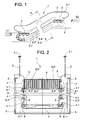
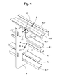
- FIG. 1 and FIG. 2 show an escalator 1 with a handrail 2.1 bearing balustrade 2 and between base plates 3 laterally guided steps 4.
- the escalator 1 connects a first floor E1 with a second floor E2.
- Casters 4.1 of the stages 4 travel on track rails 6.3 “, 6.4", or on tracks 6.1 “, 6.2”, which are fastened to the frames 7 with the fastening devices 8.
- two guide rails 6.5 are fixed to the frame 7 with a fastening device 8. These fastening devices 8 are described below with reference to FIGS. 3 to 9 described in more detail.
- Each bulkhead 7 is connected to a framework 5 of the escalator 1, for example by means of a screw connection, welded connection, press connection, riveted connection or by clinching (clinching).
- the fastening device 18 has a spring element 20 with two spring legs 20.1, 20.2 and a bearing point 22. Each spring leg 20.1, 20.2 has a clamping point 23 and a lever end 24. Between the bearing point 22 and the clamping points 23 are each a short lever arm 25 and between the clamping points 23 and the lever ends 24 each have a long lever arm 26 is arranged.
- the spring element 20 is mirror-symmetrical to its longitudinal extension, wherein the mirror plane between the two spring legs 20.1, 20.2 and orthogonal to the pivot axis 27 of the bearing 22 is arranged.
- the fastening device 18 includes a latching point 30 formed on the component 5 ', a support point 31 and a bearing receptacle 32
- FIG. 3 Locking point 30 shown has two on the component 5 'integrally formed bracket 30.1, 30.2, wherein each bracket 30.1, 30.2 each receives a long lever arm 26 when the spring element 20 is tensioned.
- the attachment of the attachment 7 "on the component 5 ' is extremely simple First, the spring element 20 or its bearing point 22 is inserted into the bearing receptacle 32, in such a way that the component 5' between the two spring legs 20.1, 20.2 is arranged However, long lever arms 26 may not yet be engaged in the latching point 30. The two spring legs 20.1, 20.2 are to be brought into a starting position 38, so that the attachment 7 "can be inserted into the support point 31. Subsequently, the attachment 7 "is inserted and aligned in the support point 31.
- Pivot axis 27 are the clamping points 23 on the attachment 7 "and press it against the support point 31, even before the spring legs 20.1, 20.2 reach the locking point 30. Due to the leverage of the short lever arm 25 and the long lever arm 26, despite manual assembly, a very high, on the attachment 7 "acting clamping force or biasing force can be generated.
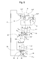
- FIG. 4 shows a single frame from the FIG. 2 with mounted rails, raceways and guide rails in three-dimensional representation.
- the bulkhead thus becomes the component 7 ', the rails to attachments 6. 1 ", 6.2", the raceways to attachments 6.3 “, 6.4” and the guide rail likewise to an attachment 6.5 " 41 of the in FIG. 3 shown fastening device 18, which is why identical Features the same reference numerals are used.
- the latching point 41 of the spring element 20 is in FIG. 8 and will be described in detail below.
- the component 7 ' are also made of thin sheet metal guide rails 9.1, 9.2 arranged. These limit a possible lifting of the rollers not shown or stepped rollers of the attachment parts 6.1 “, 6.2".
- the U-shaped guide rails 9.1, 9.2 can be spread across the longitudinal extent due to the small thickness of sheet metal and can be engaged without much effort in dovetail feet 10, which is formed on the component 7 '.
- the guide rail 9.1, 9.2 can also be fixed by means of a fastening device 8 on the component 7 '.
- FIG. 5 shows in the elevation in the FIG. 4 6 ', 6.3 “, 6.5” shown in this view, the fastening devices 8 with the tensioned spring elements 20 are much easier to see, using the example of an attachment 6.1 (running rail) also shows the active lever lengths l 1 , l 2. Due to the angled fold 29 of the spring element 20 and the arrangement of the spring element 20 on the component 7 ', these are shorter than the associated lever arms 25, 26. The active lever length l 2 of the long lever arm 26 is of course dependent on the direction of the latching applied, manual force F H.
- the effective lever length l 1 of the short lever arm 25 changes only slightly when the angled chamfer 29 and the thus formed clamping area 23 due to manufacturing tolerances a deviating the interpretation
- Lü Under design position is the theoretical position of the spring ementes 20 to understand in the clamped state, when all dimensions of the spring element 20, the component 7 'and the attachment 6.1 "are considered without tolerance deviations.
- the clamping point 23 must never exceed the dead center, that is, the active lever length l 1 of the small lever 25 must never be less than 0.
- the fastening device 8 has a very high level of reliability, which is given by the fact that a non-tensionable spring element 20 is recognized immediately during assembly and measures to remedy the problem, For example, the insertion of a metal sheet between the clamping point 23 and the attachment 6.1 "can be performed immediately.Frenched or deformed spring elements 20 are immediately recognized during inspections and / or maintenance due to lack of clamping force and can be replaced, the number of fasteners 8 over the longitudinal extent of Escalator, a moving walks or a hoistway is to be chosen so that the reliability is ensured even in the event of failure of individual spring elements 20.
- FIG. 5 also the advantageous positioning of the spring elements 20 with respect to the raceways and rails acting, external forces are shown.
- the external force F S, the tension force F F of the spring element 20 and the bending moment M L caused by the external force F S and the support of the moment M L are represented by the reaction force F R Force F S acts due to the mass and load to be carried on a step of the escalator or a pallet of a moving walk on the roller 4.1 on the attachment 6.2 ".
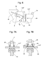
- FIG. 6 shows in a larger representation in the FIG. 5 marked section B. This shows that two attachment parts 6.3 “, 6.4" can be attached to the component 7 'with a fastening device 8.
- two attachment parts 6.3 ", 6.4" can be attached to the component 7 'with a fastening device 8.
- the insensitivity of the fastening device 8 with respect to large manufacturing tolerances comes into play.
- the contact point 51 of the component 7 ' may have a suitable shape, for example a tooth profile 43.
- a tooth profile 43 can, for example, have a greater hardness than the material of the attachment 6.3 "When the spring element 20 is tensioned, the protruding teeth of the tooth profile 43 penetrate partially into the material of the attachment 6.3". This positive locking prevents any relative movement between the component 7 'and the attachment 6.3 "in a plane which extends orthogonally to the direction of the clamping force F F of the spring element 20.
- tooth profiles 43 or profiles with sharp tips are of course also applicable, and instead of the tooth profile 43, a sliding-inhibiting coating, for example a flame-sprayed carbide hard coating or a slip-resistant or non-slip intermediate layer between the support 51, can be used and the attachment 6.3 "be arranged.
- a sliding-inhibiting coating for example a flame-sprayed carbide hard coating or a slip-resistant or non-slip intermediate layer between the support 51, can be used and the attachment 6.3 "be arranged.
- the embodiment of the bearing receptacle 32 can be seen, which is formed in the component 7 '. This is preferably not designed as a bore, but as a slot-shaped recess.
- the open end of the bearing receptacle 32 preferably extends in the opposite direction to the bearing force F P of the spring element 20. This embodiment allows for easy insertion of the spring element in the component 7 '.
- FIG. 7A shows a further embodiment possibility of the component 7 'formed support point 61 in a sectional elevation.
- a relative movement of the attachment 6.1 in the direction of its longitudinal extension is desired.
- the attachment 6.1 is only mentioned by way of example, and the other attachments, not shown, can also be fixed to the component 7 'by means of a suitably designed attachment device.
- a relative movement can be easily admitted, since the partially shown spring element 20 by the component 7 'penetrating bearing point and the locking point (both not shown) is held stationary on the component 7'.
- the support point 61 is a sliding shoe 52 arranged. This is made in the illustrated embodiment of a plastic with high strength and low creep, for example, a glass fiber reinforced plastic.
- the shoe 52 made of plastic also has vibration damping properties.
- a sliding insert 53 may be arranged, which improve the sliding properties and / or vibration damping properties between the attachment 6.1" and the clamping points 23 of the spring element 20. Furthermore, the clamping points 23 can be supported against each other by the sliding insert 53 in the direction of the sliding movement X in order to avoid lateral drifting away.
- FIG. 8 shows the engaging part 41 formed on the component 7 'in a three-dimensional view.
- the latching point 41 has a hook formed on the component 7 '71 and an insert 72 with an opening 72.1 in the assembled state, the hook 71 extends through the opening 72.1.
- the insert 72 is further secured by the supporting forces F A of the spring element 20 in the hook 71. The farther the insert 72 is located away from the bearing 22, the lower are the supporting forces F A acting on the insert 72.
- the insert 72 may be made of metal, for example made of steel, but also made of plastic.
- An insert 72 made of plastic has the advantage that vibrations are damped within the fastening device, so that the operating noise of the escalator, the moving walk or the elevator can be minimized.
- the insert 72 further has an expanding wedge 72.2, which is formed by two lateral chamfers.
- an expanding wedge 72.2 facilitates the spreading apart of the two spring legs 20.1, 20.2, so that they can be easily lifted over the lugs 72.5, 72.6 of the insert 72 and snapped into the recesses 72.3, 72.4.
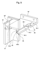
- FIG. 9 shows a guide rail of a lift in three-dimensional view, which is arranged in an elevator shaft, not shown.
- the elevator car and / or the balance weight or counterweight is performed.
- the guide rail as an attachment 80 "is fastened to the shaft wall of the elevator shaft by means of a component 90.
- a contact point 91, a The latching point 92 is formed by means of an S-shaped fold of a region of the component 90 'delimited by two parallel cuts on.
- the illustrated spring element 95 differs from the spring elements of the embodiments shown above in that it has only one spring leg 95.1.
- the features such as a clamping point 95.9, a lever end 95.4, a bearing 95.2, a short lever 95.5 and a long lever arm 95.3 are also present in this spring element 95.
- the operation and the assembly process of this fastening device 28 correspond to the preceding embodiments.
- the spring element have only one spring leg.
- sliding shoes, sliding inserts, damping inserts, tooth profiles or profiles with sharp tips and the like more can be used.
- an attachment which is fixed to a plurality of components, is connected by differently configured fastening devices with the components.
- one of the fastening devices may have a tooth profile and all other fastening devices a sliding block. Accordingly, appropriately configured attachment devices are included within the scope of the present claims.
Landscapes
- Escalators And Moving Walkways (AREA)
- Engineering & Computer Science (AREA)
- General Engineering & Computer Science (AREA)
- Mechanical Engineering (AREA)
- Display Devices Of Pinball Game Machines (AREA)
- Connection Of Plates (AREA)
Priority Applications (17)
| Application Number | Priority Date | Filing Date | Title |
|---|---|---|---|
| EP11174899A EP2548832A1 (de) | 2011-07-21 | 2011-07-21 | Bauteil mit einer Befestigungsvorrichtung für Anbauteile |
| PL12733143T PL2734465T3 (pl) | 2011-07-21 | 2012-07-09 | Element konstrukcyjny z urządzeniem mocującym dla części montażowych |
| KR1020147004256A KR102072868B1 (ko) | 2011-07-21 | 2012-07-09 | 부착물을 위한 체결 장치를 가지는 구성요소 |
| MX2014000733A MX338637B (es) | 2011-07-21 | 2012-07-09 | Componente con un dispositivo de fijacion para componentes adicionales. |
| BR112014001215A BR112014001215A2 (pt) | 2011-07-21 | 2012-07-09 | componente com um dispositivo de fixação para peças acessórias |
| EP12733143.7A EP2734465B1 (de) | 2011-07-21 | 2012-07-09 | Bauteil mit einer befestigungsvorrichtung für anbauteile |
| CA2842496A CA2842496C (en) | 2011-07-21 | 2012-07-09 | Component having a fastening apparatus for add-on parts |
| RU2014103497/11A RU2590842C2 (ru) | 2011-07-21 | 2012-07-09 | Компонент с крепежным устройством для дополнительных деталей |
| ES12733143.7T ES2539911T3 (es) | 2011-07-21 | 2012-07-09 | Componente con un dispositivo de fijación para piezas montables |
| PCT/EP2012/063361 WO2013010838A1 (de) | 2011-07-21 | 2012-07-09 | Bauteil mit einer befestigungsvorrichtung für anbauteile |
| CN201280040972.2A CN103764534B (zh) | 2011-07-21 | 2012-07-09 | 一种自动扶梯、移动步道或升降梯的构件 |
| AU2012286046A AU2012286046B2 (en) | 2011-07-21 | 2012-07-09 | Component having a fastening apparatus for add-on parts |
| US13/547,135 US9664220B2 (en) | 2011-07-21 | 2012-07-12 | Component with a fastening device for attachments |
| CL2014000152A CL2014000152A1 (es) | 2011-07-21 | 2014-01-20 | Componente de una escalera mecanica de un pasillo rodante o un elevador, contiene un dispositivo de fijacion, un elemento de resorte, un puesto de encaje y un puesto de soporte para un componente adicional a fijar, el elemento de resorte presenta un puesto de cojinete, un puesto de fijacion y un extremo de palanca. |
| CO14024334A CO6870024A2 (es) | 2011-07-21 | 2014-02-06 | Elemento de construcción con un dispositivo de ajuste para elementos adicionales |
| ZA2014/01051A ZA201401051B (en) | 2011-07-21 | 2014-02-11 | Component having a fastening apparatus for add-on parts |
| HK14109558.9A HK1196117A1 (zh) | 2011-07-21 | 2014-09-23 | 種自動扶梯、移動步道或升降梯的構件 |
Applications Claiming Priority (1)
| Application Number | Priority Date | Filing Date | Title |
|---|---|---|---|
| EP11174899A EP2548832A1 (de) | 2011-07-21 | 2011-07-21 | Bauteil mit einer Befestigungsvorrichtung für Anbauteile |
Publications (1)
| Publication Number | Publication Date |
|---|---|
| EP2548832A1 true EP2548832A1 (de) | 2013-01-23 |
Family
ID=46466562
Family Applications (2)
| Application Number | Title | Priority Date | Filing Date |
|---|---|---|---|
| EP11174899A Withdrawn EP2548832A1 (de) | 2011-07-21 | 2011-07-21 | Bauteil mit einer Befestigungsvorrichtung für Anbauteile |
| EP12733143.7A Not-in-force EP2734465B1 (de) | 2011-07-21 | 2012-07-09 | Bauteil mit einer befestigungsvorrichtung für anbauteile |
Family Applications After (1)
| Application Number | Title | Priority Date | Filing Date |
|---|---|---|---|
| EP12733143.7A Not-in-force EP2734465B1 (de) | 2011-07-21 | 2012-07-09 | Bauteil mit einer befestigungsvorrichtung für anbauteile |
Country Status (16)
| Country | Link |
|---|---|
| US (1) | US9664220B2 (ru) |
| EP (2) | EP2548832A1 (ru) |
| KR (1) | KR102072868B1 (ru) |
| CN (1) | CN103764534B (ru) |
| AU (1) | AU2012286046B2 (ru) |
| BR (1) | BR112014001215A2 (ru) |
| CA (1) | CA2842496C (ru) |
| CL (1) | CL2014000152A1 (ru) |
| CO (1) | CO6870024A2 (ru) |
| ES (1) | ES2539911T3 (ru) |
| HK (1) | HK1196117A1 (ru) |
| MX (1) | MX338637B (ru) |
| PL (1) | PL2734465T3 (ru) |
| RU (1) | RU2590842C2 (ru) |
| WO (1) | WO2013010838A1 (ru) |
| ZA (1) | ZA201401051B (ru) |
Cited By (1)
| Publication number | Priority date | Publication date | Assignee | Title |
|---|---|---|---|---|
| EP4353656A1 (de) * | 2022-10-10 | 2024-04-17 | TK Elevator Innovation and Operations GmbH | Tragstruktur für eine fahrwegvorrichtung |
Families Citing this family (5)
| Publication number | Priority date | Publication date | Assignee | Title |
|---|---|---|---|---|
| US20180118521A1 (en) | 2015-04-16 | 2018-05-03 | Inventio Ag | Escalator having common return rails |
| EP3081521A1 (de) | 2015-04-16 | 2016-10-19 | Inventio AG | Fahrtreppe mit gemeinsamen rücklaufschienen |
| EP3081522A1 (de) | 2015-04-16 | 2016-10-19 | Inventio AG | Fahrtreppe mit gemeinsamen rücklaufschienen |
| EP3205781A1 (en) * | 2016-02-12 | 2017-08-16 | Metalogenia Research & Technologies S.L. | Female part, retaining device and pin system for excavators and the like |
| EP3687934B1 (de) * | 2017-09-27 | 2021-09-08 | Inventio AG | Ausrichtvorrichtung und verfahren zur montage einer führungsschiene in einem aufzugschacht einer aufzuganlage |
Citations (7)
| Publication number | Priority date | Publication date | Assignee | Title |
|---|---|---|---|---|
| CH561659A5 (en) * | 1972-12-08 | 1975-05-15 | Kuenzler Ernst Ag | Lift running rail attachment - using a support element with bearing sections having adjustable spring loaded clamps |
| SU1000369A1 (ru) * | 1981-11-18 | 1983-02-28 | Государственный Проектно-Конструкторский Институт Технологии Монтажа Промышленного Оборудования "Гипротехмонтаж" | Устройство дл креплени направл ющей лифта |
| JPS5864677U (ja) * | 1981-10-26 | 1983-04-30 | 三菱電機株式会社 | エレベ−タ機器の締結金具 |
| JPH01127586A (ja) * | 1987-11-12 | 1989-05-19 | Mitsubishi Electric Corp | エレベータのガイドレールブラケット |
| JPH1077172A (ja) * | 1996-09-04 | 1998-03-24 | Toshiba Fa Syst Eng Kk | エレベータ |
| DE10126833A1 (de) * | 2000-06-02 | 2002-04-04 | Otis Elevator Co | Schnellverbindervorrichtung für Aufzug-Führungsschienenprofile |
| EP1679280A1 (de) | 2005-01-07 | 2006-07-12 | Inventio Ag | Einrichtung zur Befestigung von Bauteilen |
Family Cites Families (12)
| Publication number | Priority date | Publication date | Assignee | Title |
|---|---|---|---|---|
| GB722900A (en) | 1951-08-30 | 1955-02-02 | Mills James Ltd | Improvements in or relating to rail fastenings |
| US3187856A (en) * | 1961-05-01 | 1965-06-08 | Eastern Prod Corp | Acoustical ceiling suspension fastening system |
| US3102614A (en) | 1961-12-01 | 1963-09-03 | Eastern Prod Corp | Suspended ceiling clip |
| DE1500692A1 (de) * | 1966-03-24 | 1969-04-03 | S Cox Darwin | Loesbare Einbauanordnung |
| US3614340A (en) * | 1969-10-17 | 1971-10-19 | Johan L Harmsen | Securing means for power rail and/or shield |
| US3867802A (en) * | 1971-07-06 | 1975-02-25 | Vercon Products | Floor support assembly for building structures |
| US3984960A (en) * | 1975-03-03 | 1976-10-12 | Stearns Product Development Corporation | Utility building system |
| SU1027128A1 (ru) * | 1982-03-31 | 1983-07-07 | Центральное Проектно-Конструкторское Бюро По Лифтам Всесоюзного Промышленного Объединения "Союзлифтмаш" | Устройство дл креплени направл ющей лифта |
| US4559751A (en) * | 1984-03-01 | 1985-12-24 | Crystaplex Plastics Ltd. | Corrosive resistant grid construction for a suspended ceiling |
| US6327758B1 (en) * | 1999-11-01 | 2001-12-11 | Juno Manufacturing, Inc. | Resilient unitary lighting clip |
| DE10210383B4 (de) * | 2002-03-08 | 2007-03-29 | Preh Gmbh | Befestigungsfeder |
| US7381006B2 (en) * | 2005-01-07 | 2008-06-03 | Inventio Ag | Device for fastening components |
-
2011
- 2011-07-21 EP EP11174899A patent/EP2548832A1/de not_active Withdrawn
-
2012
- 2012-07-09 PL PL12733143T patent/PL2734465T3/pl unknown
- 2012-07-09 WO PCT/EP2012/063361 patent/WO2013010838A1/de active Application Filing
- 2012-07-09 RU RU2014103497/11A patent/RU2590842C2/ru not_active IP Right Cessation
- 2012-07-09 CN CN201280040972.2A patent/CN103764534B/zh active Active
- 2012-07-09 EP EP12733143.7A patent/EP2734465B1/de not_active Not-in-force
- 2012-07-09 KR KR1020147004256A patent/KR102072868B1/ko active IP Right Grant
- 2012-07-09 CA CA2842496A patent/CA2842496C/en not_active Expired - Fee Related
- 2012-07-09 MX MX2014000733A patent/MX338637B/es active IP Right Grant
- 2012-07-09 AU AU2012286046A patent/AU2012286046B2/en not_active Ceased
- 2012-07-09 ES ES12733143.7T patent/ES2539911T3/es active Active
- 2012-07-09 BR BR112014001215A patent/BR112014001215A2/pt not_active IP Right Cessation
- 2012-07-12 US US13/547,135 patent/US9664220B2/en not_active Expired - Fee Related
-
2014
- 2014-01-20 CL CL2014000152A patent/CL2014000152A1/es unknown
- 2014-02-06 CO CO14024334A patent/CO6870024A2/es unknown
- 2014-02-11 ZA ZA2014/01051A patent/ZA201401051B/en unknown
- 2014-09-23 HK HK14109558.9A patent/HK1196117A1/zh not_active IP Right Cessation
Patent Citations (7)
| Publication number | Priority date | Publication date | Assignee | Title |
|---|---|---|---|---|
| CH561659A5 (en) * | 1972-12-08 | 1975-05-15 | Kuenzler Ernst Ag | Lift running rail attachment - using a support element with bearing sections having adjustable spring loaded clamps |
| JPS5864677U (ja) * | 1981-10-26 | 1983-04-30 | 三菱電機株式会社 | エレベ−タ機器の締結金具 |
| SU1000369A1 (ru) * | 1981-11-18 | 1983-02-28 | Государственный Проектно-Конструкторский Институт Технологии Монтажа Промышленного Оборудования "Гипротехмонтаж" | Устройство дл креплени направл ющей лифта |
| JPH01127586A (ja) * | 1987-11-12 | 1989-05-19 | Mitsubishi Electric Corp | エレベータのガイドレールブラケット |
| JPH1077172A (ja) * | 1996-09-04 | 1998-03-24 | Toshiba Fa Syst Eng Kk | エレベータ |
| DE10126833A1 (de) * | 2000-06-02 | 2002-04-04 | Otis Elevator Co | Schnellverbindervorrichtung für Aufzug-Führungsschienenprofile |
| EP1679280A1 (de) | 2005-01-07 | 2006-07-12 | Inventio Ag | Einrichtung zur Befestigung von Bauteilen |
Cited By (2)
| Publication number | Priority date | Publication date | Assignee | Title |
|---|---|---|---|---|
| EP4353656A1 (de) * | 2022-10-10 | 2024-04-17 | TK Elevator Innovation and Operations GmbH | Tragstruktur für eine fahrwegvorrichtung |
| WO2024078847A1 (de) * | 2022-10-10 | 2024-04-18 | Tk Elevator Innovation And Operations Gmbh | Tragstruktur für eine fahrwegvorrichtung |
Also Published As
| Publication number | Publication date |
|---|---|
| KR20140066708A (ko) | 2014-06-02 |
| HK1196117A1 (zh) | 2014-12-05 |
| MX338637B (es) | 2016-04-25 |
| CL2014000152A1 (es) | 2014-07-11 |
| CO6870024A2 (es) | 2014-02-20 |
| EP2734465B1 (de) | 2015-03-25 |
| MX2014000733A (es) | 2014-02-19 |
| ES2539911T3 (es) | 2015-07-07 |
| KR102072868B1 (ko) | 2020-02-03 |
| US20130177351A1 (en) | 2013-07-11 |
| AU2012286046B2 (en) | 2017-07-27 |
| US9664220B2 (en) | 2017-05-30 |
| WO2013010838A1 (de) | 2013-01-24 |
| ZA201401051B (en) | 2015-10-28 |
| RU2014103497A (ru) | 2015-11-20 |
| AU2012286046A1 (en) | 2014-02-06 |
| PL2734465T3 (pl) | 2015-08-31 |
| CA2842496C (en) | 2019-04-02 |
| RU2590842C2 (ru) | 2016-07-10 |
| CN103764534B (zh) | 2016-02-17 |
| BR112014001215A2 (pt) | 2017-02-21 |
| EP2734465A1 (de) | 2014-05-28 |
| CA2842496A1 (en) | 2013-01-24 |
| CN103764534A (zh) | 2014-04-30 |
Similar Documents
| Publication | Publication Date | Title |
|---|---|---|
| EP2734465B1 (de) | Bauteil mit einer befestigungsvorrichtung für anbauteile | |
| EP3044153B1 (de) | Palette für einen fahrsteig oder stufe für eine fahrtreppe | |
| EP2900585B1 (de) | Fahrbahnsystem für eine fahrtreppe oder einen fahrsteig | |
| WO2014048808A1 (de) | Führungsleiste für eine laufschiene einer fahrtreppe oder eines fahrsteiges | |
| EP2365155A1 (de) | Vorrichtung zur Befestigung einer Geländerbrüstung | |
| WO2015113680A1 (de) | Palette für einen fahrsteig oder stufe für eine fahrtreppe | |
| EP3060511B1 (de) | Befestigungsvorrichtung zum befestigen einer stufe oder palette an einem zugmittel | |
| EP0433224B1 (de) | Zusammengesetztes Tragelement | |
| WO2013029979A1 (de) | Fahrtreppe oder fahrsteig mit einem untersichtblech | |
| DE202014100163U1 (de) | Klemmteil zur Fixierung von Geländerplatten in Halteprofilen | |
| EP1785546B1 (de) | Konsolanker zur Fixierung einer Verblendung an einer Gebäudewand | |
| EP3137406B1 (de) | Fahrbahnsystem für eine fahrtreppe oder einen fahrsteig | |
| WO2019157544A1 (de) | Verfahren zur herstellung von verbunddecken und verbunddecke | |
| DE202006011801U1 (de) | Rahmenkonstruktion für die Montage eines Sanitärgegenstandes | |
| DE102010006560A1 (de) | Tragvorrichtung und Schalungssystem | |
| DE10208359A1 (de) | Dichtungsvorrichtung für eine Bewegungsfuge | |
| EP2581521A2 (de) | Dielenanordnung sowie Vorrichtung zum Halten einer Enddiele | |
| DE202012101395U1 (de) | Anordnung zur Montage von Dachzubehörelementen auf geneigten Gebäudedächern | |
| EP3296475B1 (de) | Balkon und verfahren zur herstellung eines solchen balkons | |
| EP1873340A2 (de) | Türanlage | |
| EP1697601B1 (de) | Tragbügel zur befestigung von fassadenelementen od.dgl. an aussenwänden von gebäuden | |
| EP1679280B1 (de) | Einrichtung zur Befestigung von Bauteilen | |
| DE202018003027U1 (de) | Verbindungsstück zur winkeligen Verbindung zweier Bauteile | |
| DE102014104542A1 (de) | Befestigungsvorrichtung für Trockenbauwände | |
| DE202021104125U1 (de) | Baugruppe eines Kabeltragsystems |
Legal Events
| Date | Code | Title | Description |
|---|---|---|---|
| PUAI | Public reference made under article 153(3) epc to a published international application that has entered the european phase |
Free format text: ORIGINAL CODE: 0009012 |
|
| AK | Designated contracting states |
Kind code of ref document: A1 Designated state(s): AL AT BE BG CH CY CZ DE DK EE ES FI FR GB GR HR HU IE IS IT LI LT LU LV MC MK MT NL NO PL PT RO RS SE SI SK SM TR |
|
| AX | Request for extension of the european patent |
Extension state: BA ME |
|
| STAA | Information on the status of an ep patent application or granted ep patent |
Free format text: STATUS: THE APPLICATION HAS BEEN WITHDRAWN |
|
| 18W | Application withdrawn |
Effective date: 20130117 |