EP2548691A1 - Dispositif de déchargement pour un dispositif d'usinage de tuyaux avec un élément support et/ou une surface de dépôt déplaçables en hauteur - Google Patents
Dispositif de déchargement pour un dispositif d'usinage de tuyaux avec un élément support et/ou une surface de dépôt déplaçables en hauteur Download PDFInfo
- Publication number
- EP2548691A1 EP2548691A1 EP20110174965 EP11174965A EP2548691A1 EP 2548691 A1 EP2548691 A1 EP 2548691A1 EP 20110174965 EP20110174965 EP 20110174965 EP 11174965 A EP11174965 A EP 11174965A EP 2548691 A1 EP2548691 A1 EP 2548691A1
- Authority
- EP
- European Patent Office
- Prior art keywords
- tube
- longitudinal direction
- lance
- pipe
- movable
- Prior art date
- Legal status (The legal status is an assumption and is not a legal conclusion. Google has not performed a legal analysis and makes no representation as to the accuracy of the status listed.)
- Granted
Links
- 238000012545 processing Methods 0.000 title claims abstract description 46
- 230000008093 supporting effect Effects 0.000 title claims abstract description 17
- 238000007599 discharging Methods 0.000 title claims abstract description 5
- 238000003860 storage Methods 0.000 claims abstract description 68
- 238000005520 cutting process Methods 0.000 claims abstract description 21
- 238000000034 method Methods 0.000 claims abstract description 9
- 238000000151 deposition Methods 0.000 claims description 11
- 238000000926 separation method Methods 0.000 claims description 6
- 238000007790 scraping Methods 0.000 abstract 1
- 238000003698 laser cutting Methods 0.000 description 28
- 238000003754 machining Methods 0.000 description 16
- 238000011010 flushing procedure Methods 0.000 description 6
- 239000002184 metal Substances 0.000 description 5
- 230000001960 triggered effect Effects 0.000 description 5
- 230000005484 gravity Effects 0.000 description 4
- 230000009471 action Effects 0.000 description 3
- 230000008569 process Effects 0.000 description 3
- 238000005096 rolling process Methods 0.000 description 3
- 238000012546 transfer Methods 0.000 description 3
- 238000010276 construction Methods 0.000 description 2
- 230000008878 coupling Effects 0.000 description 2
- 238000010168 coupling process Methods 0.000 description 2
- 238000005859 coupling reaction Methods 0.000 description 2
- 238000000227 grinding Methods 0.000 description 2
- 230000001976 improved effect Effects 0.000 description 2
- 238000003780 insertion Methods 0.000 description 2
- 230000037431 insertion Effects 0.000 description 2
- 230000000284 resting effect Effects 0.000 description 2
- 238000006748 scratching Methods 0.000 description 2
- 230000002393 scratching effect Effects 0.000 description 2
- 244000089486 Phragmites australis subsp australis Species 0.000 description 1
- 230000015572 biosynthetic process Effects 0.000 description 1
- 239000002131 composite material Substances 0.000 description 1
- 238000011109 contamination Methods 0.000 description 1
- 238000001816 cooling Methods 0.000 description 1
- 238000011161 development Methods 0.000 description 1
- 238000006073 displacement reaction Methods 0.000 description 1
- 230000002349 favourable effect Effects 0.000 description 1
- 238000007654 immersion Methods 0.000 description 1
- 230000008676 import Effects 0.000 description 1
- 239000012535 impurity Substances 0.000 description 1
- 238000004519 manufacturing process Methods 0.000 description 1
- 239000000463 material Substances 0.000 description 1
- 230000002093 peripheral effect Effects 0.000 description 1
- 238000003672 processing method Methods 0.000 description 1
- 230000000630 rising effect Effects 0.000 description 1
- 238000007665 sagging Methods 0.000 description 1
Images


Classifications
-
- B—PERFORMING OPERATIONS; TRANSPORTING
- B23—MACHINE TOOLS; METAL-WORKING NOT OTHERWISE PROVIDED FOR
- B23K—SOLDERING OR UNSOLDERING; WELDING; CLADDING OR PLATING BY SOLDERING OR WELDING; CUTTING BY APPLYING HEAT LOCALLY, e.g. FLAME CUTTING; WORKING BY LASER BEAM
- B23K26/00—Working by laser beam, e.g. welding, cutting or boring
- B23K26/36—Removing material
- B23K26/38—Removing material by boring or cutting
-
- B—PERFORMING OPERATIONS; TRANSPORTING
- B23—MACHINE TOOLS; METAL-WORKING NOT OTHERWISE PROVIDED FOR
- B23K—SOLDERING OR UNSOLDERING; WELDING; CLADDING OR PLATING BY SOLDERING OR WELDING; CUTTING BY APPLYING HEAT LOCALLY, e.g. FLAME CUTTING; WORKING BY LASER BEAM
- B23K26/00—Working by laser beam, e.g. welding, cutting or boring
- B23K26/70—Auxiliary operations or equipment
-
- B—PERFORMING OPERATIONS; TRANSPORTING
- B23—MACHINE TOOLS; METAL-WORKING NOT OTHERWISE PROVIDED FOR
- B23K—SOLDERING OR UNSOLDERING; WELDING; CLADDING OR PLATING BY SOLDERING OR WELDING; CUTTING BY APPLYING HEAT LOCALLY, e.g. FLAME CUTTING; WORKING BY LASER BEAM
- B23K26/00—Working by laser beam, e.g. welding, cutting or boring
- B23K26/08—Devices involving relative movement between laser beam and workpiece
- B23K26/0823—Devices involving rotation of the workpiece
-
- B—PERFORMING OPERATIONS; TRANSPORTING
- B23—MACHINE TOOLS; METAL-WORKING NOT OTHERWISE PROVIDED FOR
- B23K—SOLDERING OR UNSOLDERING; WELDING; CLADDING OR PLATING BY SOLDERING OR WELDING; CUTTING BY APPLYING HEAT LOCALLY, e.g. FLAME CUTTING; WORKING BY LASER BEAM
- B23K37/00—Auxiliary devices or processes, not specially adapted to a procedure covered by only one of the preceding main groups
- B23K37/04—Auxiliary devices or processes, not specially adapted to a procedure covered by only one of the preceding main groups for holding or positioning work
-
- B—PERFORMING OPERATIONS; TRANSPORTING
- B23—MACHINE TOOLS; METAL-WORKING NOT OTHERWISE PROVIDED FOR
- B23Q—DETAILS, COMPONENTS, OR ACCESSORIES FOR MACHINE TOOLS, e.g. ARRANGEMENTS FOR COPYING OR CONTROLLING; MACHINE TOOLS IN GENERAL CHARACTERISED BY THE CONSTRUCTION OF PARTICULAR DETAILS OR COMPONENTS; COMBINATIONS OR ASSOCIATIONS OF METAL-WORKING MACHINES, NOT DIRECTED TO A PARTICULAR RESULT
- B23Q7/00—Arrangements for handling work specially combined with or arranged in, or specially adapted for use in connection with, machine tools, e.g. for conveying, loading, positioning, discharging, sorting
- B23Q7/04—Arrangements for handling work specially combined with or arranged in, or specially adapted for use in connection with, machine tools, e.g. for conveying, loading, positioning, discharging, sorting by means of grippers
-
- B—PERFORMING OPERATIONS; TRANSPORTING
- B23—MACHINE TOOLS; METAL-WORKING NOT OTHERWISE PROVIDED FOR
- B23K—SOLDERING OR UNSOLDERING; WELDING; CLADDING OR PLATING BY SOLDERING OR WELDING; CUTTING BY APPLYING HEAT LOCALLY, e.g. FLAME CUTTING; WORKING BY LASER BEAM
- B23K2101/00—Articles made by soldering, welding or cutting
- B23K2101/04—Tubular or hollow articles
- B23K2101/06—Tubes
-
- Y—GENERAL TAGGING OF NEW TECHNOLOGICAL DEVELOPMENTS; GENERAL TAGGING OF CROSS-SECTIONAL TECHNOLOGIES SPANNING OVER SEVERAL SECTIONS OF THE IPC; TECHNICAL SUBJECTS COVERED BY FORMER USPC CROSS-REFERENCE ART COLLECTIONS [XRACs] AND DIGESTS
- Y10—TECHNICAL SUBJECTS COVERED BY FORMER USPC
- Y10T—TECHNICAL SUBJECTS COVERED BY FORMER US CLASSIFICATION
- Y10T83/00—Cutting
- Y10T83/202—With product handling means
- Y10T83/2092—Means to move, guide, or permit free fall or flight of product
- Y10T83/22—Means to move product laterally
- Y10T83/2205—Reciprocating means
Definitions
- the present invention relates to an unloading apparatus for a processing apparatus for processing pipes, which has a catching lance movable in the tube longitudinal direction (X-direction) and insertable into the interior of a pipe to be processed, and a processing method using such unloading apparatus.
- a tube is understood to mean an elongated body (an elongated workpiece) whose length is generally substantially greater than its cross-section and which is made of a substantially inflexible material. Tubes can have any open or closed cross-sectional shape, with round and rectangular tubes represent the most common tubes. Tubular components made from tubes by laser cutting are referred to in this application as tube parts.
- Fig. 1 shows a known as "TruLaser tube” processing plant 1 for laser cutting of tubes 2 , which is referred to as a laser cutting machine and is designed for processing of tubes with an arbitrary cross-sectional shape.
- the illustrated laser cutting machine 1 comprises a feeding device 3 for laterally feeding a pipe 2 to be cut to the laser cutting machine 1, a processing device 4 for laser cutting pipe parts from the pipe 2 and an unloading device 5 for unloading the cut pipe parts from the laser cutting machine 1. All essential functions of Laser cutting machine 1 are controlled by means of a numerical control device 6 .
- the feeding device 3 comprises a rotary and feed device 7 serving as a workpiece movement device, and a machine bed 8 with guide rails 9 and a push-through device 10.
- the rotary and feed device 7 is driven on the guide rails 9 in a motor-driven manner in the feed direction 11 .
- the rotating and feeding device 7 On the side facing a pipe 2 to be supplied, the rotating and feeding device 7 has a clamping device 12 , which is rotatably controlled in the direction of the double arrow 13 and the supplied pipe 2 from the outside and clamps stationary.
- the supplied pipe 2 is supported by at least one integrated into the machine bed 8 workpiece support 14 .
- the tube 2 is guided through the push-through device 10 .
- the push-through device 10 is designed so that the clamped tube 2 is guided in the feed direction 11 and not clamped stationary.
- the tube 2 is rotatable about the axis of rotation 13 in the push-through device 10.
- the processing device 4 comprises a laser beam source 15 for generating a laser beam 16, a processing head 17 and a beam guide 18, which the Laser beam 16 leads from the laser beam source 15 to the processing head 17.
- the laser beam 16 emerges from the processing head 17 and is focused at a processing point F on the outer peripheral surface of the clamped tube 2.
- the unloading device 5 is provided, which dissipates the cut from the pipe 2 pipe parts and the remaining pipe from the laser cutting machine 1.
- a loading device 19 as an automation component, with which a pipe 2 is automatically conveyed to a transfer position and transferred to the feeding device 3 of the laser cutting machine 1.
- the mechanical arrangement of laser cutting machine 1 and the loading device 19 is referred to as a production cell 20 .
- the turning and feeding device 7 When the pipe 2 supplied via the loading device 19 is arranged in the transfer position, the turning and feeding device 7 is initially in a starting position remote from the machining head. For pipe processing, the turning and feeding device 7 moves from its position with the clamping device 12 open so far in the direction of the supplied pipe 2 until the end of the pipe 2 facing away from the machining head 17 comes to lie within the clamping device 12. The clamping device 12 is closed and thereby clamped the tube 2 at the rotary and feed device 7 stationary. The rotating and advancing device 7 and the tube 2 move together in the direction of the machining head 17.
- the tube 2 initially runs with its end facing the machining head 17 into the push-through device 10 and is moved in the feed direction 11 through the push-through device 10, wherein the tube 2 in the push-through device 10 is rotatable about the axis of rotation 13.
- the tube 2 is delivered by the movement of the rotary and feed device 7 in the feed direction 11 relative to the machining head 17 in the desired processing position.
- auxiliary equipment eg a hollow lance
- the carriage has a horizontal support plate for supporting the auxiliary device, which is displaced controlled by servo drives in the vertical direction.
- an unloading device of the type mentioned which has at least one movable in the vertical direction, in particular roller-shaped support member for supporting the catching lance and / or movable in the vertical direction shelf for depositing at least one in the cutting machining of the pipe to be separated pipe section.
- the catching lance, the at least one pipe section, or both are supported to prevent deflection or damage of the catching lance when pipe sections fall on the catching lance or when carrying pipe sections through the catching lance.
- the height-adjustable support element for the catching lance is part of the unloading device, so it is facing away from the turning and feeding device Side of the machining position arranged.
- the support element can be adjusted in height to the catching lance and thus used as a support point for the catching lance (English: "Catcher”). This prevents bowing of the lance due to its own weight or due to the weight of threaded pipe sections and thus leads to improved rigidity of the assembly, to reduce vibration and to increase the life of the fishing lance. In this way, a better accuracy in the processing is achieved and the formation of scratches on the tube inside by contact between the lance and tube can be avoided.
- a depositing surface can be used for supporting the pipe or pipe sections to be separated from the pipe during the cutting process.
- the storage surface is arranged for this purpose in the region of the processing point and supports during processing at least one pipe section to be separated. In this case, it is not necessary to catch the separated pipe sections with the catching lance.
- the pipe sections can instead be stored on the shelf after the cutting process.
- the catch lance remains centered in the pipe and in the pipe sections and does not come to a contact of the pipe inner wall with the catch lance.
- the pipe sections can be stored by a controlled (slow) lowering movement of the shelf on the catch lance, instead of falling by gravity on the lance uncontrolled. In this way, scratches on the pipe inside and damage to the catch lance are avoided.
- both aforementioned measures are combined.
- a scraper which is preferably movable in the tube longitudinal direction, comprises the support element, which is designed in particular in the form of a support roller. To support the catch lance, the support element on the It is advantageous if the scraper itself is movably mounted in the vertical direction, so that during the movement of the scraper in the height direction, the support element is moved in the height direction with.
- the wiper typically comprises a wiper element for wiping off the tube sections arranged on the catching lance and a support element in the form of one (or more) support rollers on which the catching lance can rest.
- a wiper element for wiping off the tube sections arranged on the catching lance
- a support element in the form of one (or more) support rollers on which the catching lance can rest.
- the scraper and / or the support roller in the height direction (Z direction) can be mounted sprung.
- the scraper or the support roller are displaceable in this case typically against a force acting against the direction of gravity spring force.
- the scraper on a scraper which is slidably mounted on the scraper in the tube longitudinal direction or in the feed direction of the tube, and indeed type-safe manner against the action of a spring force. Since it may possibly lead to jamming of pipe parts between a pipe part and the scraper when stripping pipe parts, it is advantageous if the typical plate-shaped scraper perform at a too high load overload protection as an evasive movement in the feed direction of the tube (in the positive X direction) can.
- the force at which the evasive movement of the scraper element is triggered can be adjusted continuously, for example by a mechanical force limiter.
- the triggering of the compensating movement can be detected for example by means of a proximity switch to stop the further advancement of the tube in the tube longitudinal direction.
- the scraper on a Abstreiferhalterung which is arranged to be vertically movable on a movable in the tube longitudinal direction (X direction) Abstreiferschlitten.
- the scraper is flexibly positionable, the position of the scraper along the catch lance so flexible to the different sizes of the pipes to be cut or to the number and size of the pipe sections customizable.
- the support surface is formed on a movable in the tube longitudinal direction (X direction) storage slide.
- the storage surface of the storage carriage can preferably be moved (controlled) not only in the tube longitudinal direction but also in at least one other direction. The movement in the further direction takes place either by moving the tray carriage as a whole or by the fact that the storage surface is moved relative to the bearing storage carriage.
- the storage surface can be positioned during the processing of a pipe below the pipe to be deposited or supported and in the Z direction to the pipe, so that a cut pipe part does not fall on the catching lance, but is supported from below by the storage surface. After the end of the machining, the catching lance can be pulled out of the pipe part without touching the pipe part and damaging the pipe surface.
- the cut pipe part can be removed directly from the storage surface or moved with the storage carriage to another position in the tube longitudinal direction and unloaded there.
- the storage surface is additionally movable in at least one direction other than the tube longitudinal direction, it is also possible to position the wiper carriage or the catching lance carriage directly at the processing site, for example when thin tubes are to be processed and collected on a thin, short catching lance ,
- the storage carriage to a boom for moving the support surface of the storage carriage transversely to the tube longitudinal direction or to the machine axis.
- the depositing surface can be moved away from the machine longitudinal axis when the stripping carriage or the catching lance carriage carrying the catching lance is to be positioned next to the processing point so that collisions can be prevented in a particularly simple manner.
- the storage surface is mounted vertically adjustable on the storage carriage.
- the scraper carriage or catcher sled (s) can be moved under the shelf, or vice versa.
- the height adjustment of the shelf which e.g. can be realized by attaching the shelf to a controlled in height slide, used to make the shelf to the outer circle of the tube to be supported by the shelf.
- the storage surface may in this case be designed in particular prismatic, i. starting from a the top of the shelf forming, extending in the tube longitudinal edge starting transversely to the tube longitudinal direction rise on both sides, so that a lateral rolling or slipping of overlying pipe parts is prevented.
- the depositing surface of the depositing carriage is pivotable between a first, horizontal position for depositing pipe sections to be separated from the pipe and a second, inclined position for discharging pipe sections separated from the pipe.
- a pivoting device e.g. serve in the form of a hydraulic or pneumatic cylinder whose piston engages a free end of the shelf. Due to the pivoting movement of the shelf surface resting pipe parts can be easily unloaded.
- the unloading device has both a scraper with a support element and a storage carriage with a storage surface, so that both the catching lance and the pipe or the pipe sections can be supported during or after processing. In this way, a particularly good stability and precision machining is achieved.
- the catching lance can be arranged on two catching lance holders which are independently height-adjustable, ie movable in the Z-direction perpendicular to the tube longitudinal direction.
- the catch lance can not only be changed in height, for example, to make it to the upper pipe inside, but it can also be set at an angle to the X-axis obliquely upwards.
- the Fanglanzenhalterept are typically mounted in the pipe longitudinal direction (X-direction) movable.
- the Fanglanzenhalteronnet are mounted on two independently movable in the tube longitudinal direction Fanglanzenschlitten.
- the support distance of the Fanglanzenhalteronne can be selectively varied and adjusted depending on the length and weight of the lance and the diameter and weight of the pipe to be machined: For long lances and heavy pipe parts, the support distance can be increased to a deflection of the lance and reduce the load on the brackets.
- the catching lance is displaceably mounted on at least one catching lance holder in the tube longitudinal direction in order to be able to execute an evasive movement if the forces acting on the catching lance (in the positive or negative X-direction) become too great.
- the displacement can take place as in the stripping against the action of a spring force, wherein the load at which the evasive movement is triggered, can also be adjusted via a force limiter.
- a compensation movement in both the feed direction of the tube (in the positive X direction) and counter to the feed direction (in the negative X direction) is favorable, since deadlocks can occur both during retraction and when retracting the lance from the tube.
- the occurrence of the compensation movement can be detected by means of a proximity switch to stop further movement of the lance in the tube longitudinal direction.
- the unloading device has an inclined discharge surface, which adjoins the storage surface transversely to the tube longitudinal direction.
- the upper end of the inclined discharge surface is in this case at a height arranged, which coincides with the height of the lower end of the shelf in the inclined position to pass pipes or pipe parts in a controlled manner in collection containers or transport facilities. Due to the (stationary) unloading surface, which extends over the entire travel path of the storage sled or the catching sled in the tube longitudinal direction, it is prevented that the depositing surface during the process in the tube longitudinal direction collides with poorly positioned collecting containers and possibly hooked there.
- the catcher sled, the scraper carriage and the storage sled may be attached to guide rails of a pipe longitudinally extending (longitudinal) support.
- the guide rails allow a particularly simple and therefore cost-effective leadership.
- the carriages can be moved independently of one another along the guide rails and be delivered in a desired position along the carrier.
- guide rails can also be mounted directly on the floor of the machine hall, so that the carriages are movable directly on the floor.
- An evasive movement of the tray carriage in this case may be e.g. can be realized at a branch of one of the guide rails, on which the storage carriage along a branching guide rail portion which extends in a direction different from the tube longitudinal direction, can be moved.
- Another aspect of the invention relates to a method for cutting a pipe with a laser machining apparatus, which is associated with an unloading device as described above, comprising the steps: inserting the catching lance into the interior of a pipe to be cut until a collecting opening of the catching lance at a Positioning of a laser beam is positioned, moving the support element - eg by moving the scraper - and / or the shelf in the vertical direction (Z direction) until the catch lance from the support element and / or the at least one pipe section to be separated is supported by the contact surface of the storage carriage , Separating the at least one pipe section from the tube by means of the laser beam, and retraction of the catching lance from the pipe section.
- the catching lance is supported by the support element of the scraper during the machining of the pipe and during the stripping of the cut pipe parts, so that they can bend less or not at all and vibrations are reduced.
- the tube part to be separated off or separated is supported by the depositing surface of the depositing carriage during processing or during insertion or removal of the catching lance. In this way contact between the catching lance and the inner surface of the pipe can be completely avoided since the lance is not suitable for catching the cut parts, but only for the discharge of metal splashes.
- the lance is switched on or executed in the center of the pipe and the cut pipe parts remain on the shelf, scratches on the tube inside can therefore be avoided.
- a scraper is not necessarily needed in this case.
- the catching lance can be moved in height (in the Z-direction) before or after the separation of the at least one pipe section in order to minimize the distance to the cutting edge during the cutting process.
- the catching lance can be aligned at an angle to the tube longitudinal axis (X-axis) during insertion into the tube to be cut and / or during withdrawal from the or the tube sections in the Z-direction.
- the deflection of a long, thin lance is thus compensated and collisions between the lance and the pipe end and the grinding of the lance on the pipe inside can be prevented.
- the alignment of the catch lance at an angle to the pipe axis can be done here by the Fanglanzenhalterept, where the catch is mounted, are delivered at different positions in the height direction.
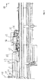
- Fig. 2 schematically shows a discharge device 5, which instead of the in Fig. 1 shown unloading device 5 in the laser cutting machine 1 of Fig. 1 Use finds.
- the unloading device 5 has a (longitudinal) carrier 21 , which in the tube longitudinal direction (X-direction of an XYZ coordinate system) to the machine bed 8 (see. Fig. 1 ).
- X guide rails 22 are mounted on the support 21 extending in the tube longitudinal direction.
- the unloading device 5 has a storage carriage 23 with a depositing surface 24, a catching lance 27 mounted on one side on two catching lance slides 25, 26 and a scraper 29 arranged on a scraper carriage 28 .
- the storage carriage 23 is guided in the tube longitudinal direction X.
- the storage carriage 23 is provided with a drive (not shown) by means of the in Fig. 1 shown control device 6 controlled and controlled displaced.
- the storage surface 24 of the tray carriage 23 is formed in the present example as a prismatic shaped tray table, which can be made across a boom 30 in a direction (Y direction) transverse to the tube longitudinal dimension X over the top of the carrier 21 and withdrawn, so that the shelf 24 no longer protrudes into the region of the pipe-facing side of the carrier 21 into it.
- the transverse arm 30 is attached to a Z-slide (not shown) of the storage carriage 23, which can be moved by a drive (not shown), so that the storage surface 24 of the storage carriage 23 is controlled (by the control device 6) at height (Z).
- Direction can be hired to the diameter or envelope of the processed or to be processed pipes.
- the shelf 24 of in Fig. 2 shown tray carriage 23 is pivotable between a first and a second angular position.
- first, horizontal position in Fig. 2 not shown
- pipe parts are stored without rolling or slipping on the shelf 24.
- the prismatic, rising to the sides shelf surface 24 prevents the lateral rolling or slipping of overlying pipes or pipe parts.
- deposited pipe parts can be subsequently transported by moving the tray carriage 23 in the tube longitudinal direction X to another position along the support 21 and unloaded there by hand or by tilting the shelf 24.
- the storage carriage 23 is moved programmatically in the pipe longitudinal direction X.
- a (not shown) hydraulic cylinder serves to the shelf 24 from the first, horizontal position to the second, inclined position (in Fig. 2 shown) too swivel and vice versa.
- a free end of the storage surface 24 is coupled for movement with a piston rod of the hydraulic cylinder.
- an oblique discharge surface 31 is mounted on the machine bed, which extends in the tube longitudinal direction X along the entire carrier 21.
- An upper end of the discharge surface 31 in this case adjoins a lower end of the storage surface 24 in its inclined position.
- the discharge surface 31 is used, for example, to prevent the moving storage surface 24 hooked with poorly positioned Sammel laborem.
- the sloping discharge surface 31 is typically arranged with its lower end in its height (Z-direction) so that the tube parts can be discharged without additional lifting devices in euro-grid boxes (reject height 900mm).
- the storage surface 24 of the storage carriage 23 can be moved by means of the transverse arm 30 in a retracted position on the side facing away from the tube of the carrier 21.
- the storage surface 24 can thus be moved away from the machine longitudinal axis in the Y direction, for example, when the wiper carriage 28 directly after the processing position (see. Fig. 1 ) should be arranged.
- the catching lance 27 is mounted on two Fanglanzenhaltern 32, 33 , which are attached to a respective one in the tube longitudinal direction X traversable Fanglanzenschlitten 25, 26 .
- the catch lance 27 protrudes in the tube longitudinal direction X on the rotary and feed device 7 (see. Fig. 1 ) in front.
- the catching lance slides 25, 26 are each coupled to a drive unit of a motorized catching lance drive.
- the drive unit has an electric drive motor. From this, a driving gear not described in detail in the figures is driven, which in turn engages in a drive rack, which is attached to the cross-member 21
- the catching lance slides 25, 26 are coupled and jointly movable with the catching lance 27 in the tube longitudinal direction X.
- a longitudinal guide This is a conventional linear guide, which comprises a guide rail mounted on the carrier 21.
- the guide rail cooperates in the usual way with a catching lance-side longitudinal guide device of conventional construction provided on the catching lance slides 25, 26.
- the catching lance holders 32, 33 are independent of each other by means of an electric drive motor, which is arranged on the back of the catching lance slides 25, 26 (in Fig. 3 not visible), via pinion 48 and timing belt 49 in height adjustable.
- the catch lance 27 can be aligned at an angle to the tube longitudinal axis X, as will be described in more detail below.
- the two Fanglanzenhalterept 32, 33 mechanically (rigid) can be coupled together, for example by means of a metal bridge 34. In this way, the be absorbed by the catch lance 27 and the moments created on this resting tubular parts as a composite, whereby the stability and rigidity of the arrangement is improved.
- the catching lance 27 is mounted on a lance coupling 35 arranged on the sheet-metal bridge 34, which allows the replacement of the catching lance 27.
- the lance coupling 35 is slidably mounted on a guide rail 36 in the tube longitudinal direction X to allow an evasive movement of the catch lance 27, if it comes when retracting the catch lance 27 into the tube 2 or when retracting the catch lance 27 from the tube 2 to collisions.
- the force in the X-direction, in which the compensation movement is triggered, can be adjusted continuously via a mechanical Krafibe dictionary 37.
- the release force can be adjusted depending on the weight and dimensions of the pipe to be machined 2 or depending on the size and length of the catch lance 27.
- the fishing lance 27 is at its free end with an in Fig. 3 recognizable Auffangöffnüng 38 provided.
- the catch lance 27 for example the in EP 1454 700 A1 described cooling and / or Spüllanze. It can alternatively be designed as a "sacrificial lance" without flushing function.
- the catching lance is designed at its end with a spoon-shaped collecting opening 38 without Spülfluidzugang to catch spatter.
- the collecting opening 38 is arranged in the interior of the pipe 2 to be processed below the processing point F of the laser cutting beam 16 (see. Fig. 1 ).
- resulting metal splash arrive at a Spüllanze through the collecting opening 38 into the interior of the lance 27, from where they are removed with the aid of a flushing medium.
- the flushing medium is fed via hoses in the catch lance 27 and - loaded with impurities - discharged from the catch lance 27.
- the inlet and outlet lines for the flushing medium are housed protected inside a attached to the catch lances 25, 26 drag chain,
- the scraper 29 comprises a scraper element 39 and a support element in the form of a support roller 40.
- the scraper element 39 is plate-like and has a U-shaped passage opening 41 , where it is penetrated by the catch lance 27.
- the support roller 40 is rotatably mounted on a Abstreiferhalterung 42 and serves to support the catch lance 27 during the laser processing and unloading of pipe sections.
- the Abstreiferhalterung 42 is spring-mounted in the Z direction and in height (in the Z direction) relative to the Abstreiferschlitten 28 slidably.
- the wiper carriage 28 with the wiper 29 is coupled to a drive unit of a (not shown) motor scraper drive.
- the drive unit of the motorized scraper drive comprises an electric drive motor. This drives a drive gear, which in turn meshes with a counter toothing of the drive rack. Accordingly, the Antfiebszahnstange forms the motorized Fanglanzenantrieb and the motorized scraper drive common support structure-side drive device.
- the motor scraper drive is the scraper carriage 28 with the scraper 29 relative to Laser cutting head 17 in the tube longitudinal direction X movable.
- To guide the scraper carriage 28 and the scraper 29 during its movement in the tube longitudinal direction X is an unspecified scraper Langs Adjust.
- the wiper longitudinal guide is also a conventional linear guide.
- an overload protection device 43 is provided on the stripper holder 42, which comprises two tension springs 44 and a (further) mechanical force limiter 45 .
- the deflection length of the wiper element 38 in the tube longitudinal direction X is predetermined by the spring travel of the two tension spring 42 and is for example 120 mm.
- the force from which an evasive action is triggered is manually adjustable via the mechanical force limiter 45 in the range of approximately 100 N to 1500 N, depending on the weight of the tube parts and the lance 27.
- the set force is indicated by a pointer on the force limiter 45
- a triggering of the evasive movement is detected by a proximity switch 46 attached to the wiper carriage 28.
- the associated switching lug is designed so that it continues to cover the proximity switch 46 even when moving the Abstreiferhalterung 42 in height.
- Fig. 5 the discharge side of the pipe processing machine 1 is shown in a side view.
- a relatively large diameter pipe 2 is to be machined.
- the catch lance 27 is shown with a much smaller diameter.
- the catching lance 27 immersed in the interior of the tube 2 can also have a larger diameter adapted to the tube diameter.
- a large lance diameter in turn allows a large fishing lance length, since for the Flushing medium inside the catching lance 27 flow cross sections can be provided, which allow a functionally reliable supply and removal of flushing medium also over relatively long path lengths.
- a large diameter of the fishing lance 27 offers the possibility of carrying out the catching lance with the increased rigidity required for a long length.
- the catching lance 27 and the stripper 29 are first positioned with the laser cutting beam switched off in the tube longitudinal direction X, as shown in FIG Fig. 6 is shown.
- the catching lance slides 25, 26 are numerically controlled by means of the motor drives in the tube longitudinal direction X arranged such that the collecting opening of the catching lance 27 is penetrated by the machining axis 47 of the laser cutting head 17.
- the fishing lance 27 runs at the free end of the pipe to be machined 2 in the pipe interior. The pipe end is then in front of the desired dimension via the machining axis 47 of the laser cutting head 17 to the discharge side of the laser cutting machine 1 out.
- the catch lance 27 can dive into the interior of the tube 2 with only a slightly larger inner diameter, without damaging the inner surface of the tube 2. It is understood that the inclination of the catch lance 27 along its travel in the tube longitudinal direction 27 may possibly be changed.
- the wiper carriage 28 is moved by means of the numerically controlled motor scraper drive in the tube longitudinal direction X in a position in which it has a distance from the machining axis 47 of the laser cutting head 17 in the tube longitudinal direction X, which on the total length of or after the tube processing is tuned to unload finished parts. On the total length of the finished parts to be unloaded is also tuned so that the cutting head side projection of the catch lance 27 against the wiper 29th
- the storage carriage 23 can be arranged under the pipe 2 and be employed in the Z direction to the pipe 2.
- the tube 2 is supported during and / or after processing by the shelf 24. This is advantageous when heavy pipes are to be cut or when unloaded without scratching.
- the unloading position 23 of the cutting head 23 between the cutting head 17 and the Abstreiferschlitten 28 is disposed below the tube 2. If thin-walled pipes are to be machined or short pipe parts are to be cut, support by the support surface 24 is unnecessary or even a hindrance.
- the shelf 24 by means of the cross arm 30 are brought into a retracted position on the side facing away from the tube 2 of the carrier 21, so that the Abstreiferschlitten 28 can be positioned directly after the processing position F.
- Fig. 7 shows the catch lance 27 is raised after immersion in the tube 2 by a movement of the Fanglanzenhalterungen 32, 33 in the Z direction and just (for example, about 3 mm) positioned below the upper tube inside.
- the scraper 29 is also raised in the Z direction, so that the support roller 40 supports the catch lance 27.
- the chuck 12 of the rotating and feeding device 7 is rotated with the tube fixed thereto by 360 ° in the tube circumferential direction.
- a separation cut continuous in the tube circumferential direction is created on the tube 2.
- Contamination of the pipe inner wall by the metal splashes formed during the cutting operation is prevented by means of the catch lance 27.
- a severed by the separating cut from the pipe 2 pipe section is either automatically deposited under gravity on the catch lance 27 or supported from below by the shelf 24 of the tray carriage 23 and possibly stored by controlled process the shelf 24 down on the lance 27.
- the tube 2 with switched off laser cutting beam 18 by moving the rotary and feed device 7 in the direction of the Laser cutting head 17 can be postponed.
- the threaded on the catch lance 27 pipe section is moved by the leading end of the tube 2 in the direction of the wiper 29.
- the support surface 24 of the delivery table 23 is pivoted into the inclined unloading position.
- the catch lance 27 moves numerically controlled from its working position according to Fig. 7 in the unloading position according to Fig. 5 , In this case, the catch lance 27 performs a relative movement to the scraper 29.
- the pipe sections whose diameter exceeds the width of the passage opening 41 on the scraper 29, stripped by the scraper 29 of the catch lance 27.
- the pipe sections fall under gravity on the (inclined) shelf 24 of the tray table 23 and then roll or slide on the inclined discharge surface 31, from where they are stored in not shown in detail precast containers and finally discharged from the vicinity of the laser cutting machine 1.
- the storage surface 24 of the storage table 23 during the extension of the catch lance 27 may be set in a horizontal position. In this case, the pipe sections fall on the shelf 24 and remain there. By moving the tray carriage 23 along the carrier 21 and then tilting the tray surface 24, the tube parts can be unloaded at the desired position.
Landscapes
- Engineering & Computer Science (AREA)
- Physics & Mathematics (AREA)
- Optics & Photonics (AREA)
- Mechanical Engineering (AREA)
- Plasma & Fusion (AREA)
- Laser Beam Processing (AREA)
- Spray Control Apparatus (AREA)
Priority Applications (4)
| Application Number | Priority Date | Filing Date | Title |
|---|---|---|---|
| EP11174965.1A EP2548691B1 (fr) | 2011-07-22 | 2011-07-22 | Dispositif de déchargement pour un dispositif d'usinage de tuyaux avec une surface de depôt déplaçables en hauteur ; Méthode d'usinage par découpe utilisant un tel dispositif |
| US13/551,654 US20130020295A1 (en) | 2011-07-22 | 2012-07-18 | Unloading Device for a Processing Device for Processing Pipes and Related Methods |
| KR1020120079310A KR101410106B1 (ko) | 2011-07-22 | 2012-07-20 | 파이프를 가공하는 가공 장치용의 언로딩 장치 |
| CN201210351942.5A CN102922146B (zh) | 2011-07-22 | 2012-07-20 | 用于加工管的加工装置的卸料装置 |
Applications Claiming Priority (1)
| Application Number | Priority Date | Filing Date | Title |
|---|---|---|---|
| EP11174965.1A EP2548691B1 (fr) | 2011-07-22 | 2011-07-22 | Dispositif de déchargement pour un dispositif d'usinage de tuyaux avec une surface de depôt déplaçables en hauteur ; Méthode d'usinage par découpe utilisant un tel dispositif |
Publications (2)
| Publication Number | Publication Date |
|---|---|
| EP2548691A1 true EP2548691A1 (fr) | 2013-01-23 |
| EP2548691B1 EP2548691B1 (fr) | 2016-08-31 |
Family
ID=45023526
Family Applications (1)
| Application Number | Title | Priority Date | Filing Date |
|---|---|---|---|
| EP11174965.1A Active EP2548691B1 (fr) | 2011-07-22 | 2011-07-22 | Dispositif de déchargement pour un dispositif d'usinage de tuyaux avec une surface de depôt déplaçables en hauteur ; Méthode d'usinage par découpe utilisant un tel dispositif |
Country Status (4)
| Country | Link |
|---|---|
| US (1) | US20130020295A1 (fr) |
| EP (1) | EP2548691B1 (fr) |
| KR (1) | KR101410106B1 (fr) |
| CN (1) | CN102922146B (fr) |
Cited By (8)
| Publication number | Priority date | Publication date | Assignee | Title |
|---|---|---|---|---|
| CN103786037A (zh) * | 2014-02-24 | 2014-05-14 | 福建省三明机床有限责任公司 | 斜横梁卸荷复合导轨结构 |
| CN105033491A (zh) * | 2015-08-18 | 2015-11-11 | 江苏新扬子造船有限公司 | 直管与套管调速定位滚动手工焊接流水线的操作方法 |
| CN110116313A (zh) * | 2019-05-21 | 2019-08-13 | 安徽星马专用汽车有限公司 | 一种轻量化混凝土运输车焊接法兰切割用移动升降小车 |
| CN110153269A (zh) * | 2019-05-23 | 2019-08-23 | 太原向明智能装备股份有限公司 | 一种自动冲断落料收集装置 |
| DE102018122717A1 (de) * | 2018-09-17 | 2020-03-19 | Trumpf Werkzeugmaschinen Gmbh + Co. Kg | Verfahren zur schneidenden Bearbeitung von Rohren in einer Laserrohrschneidmaschine sowie Laserrohrschneidmaschine |
| IT201900011103A1 (it) * | 2019-07-08 | 2021-01-08 | Adige Spa | Macchina per il taglio laser di tubi provvista di un'apparecchiatura per la pulitura dei tubi in lavorazione |
| WO2021175556A1 (fr) * | 2020-03-06 | 2021-09-10 | Trumpf Werkzeugmaschinen Gmbh + Co. Kg | Machine-outil à laser pour usinage de pièces de fabrication |
| CN113547209A (zh) * | 2021-07-14 | 2021-10-26 | 赵重 | 一种具有下料接取结构的金属管材加工用激光机 |
Families Citing this family (26)
| Publication number | Priority date | Publication date | Assignee | Title |
|---|---|---|---|---|
| CN103317379B (zh) * | 2013-07-15 | 2015-05-20 | 旭东机械(昆山)有限公司 | 管件加工设备的下料装置 |
| CN103624408B (zh) * | 2013-11-25 | 2015-07-22 | 武汉新特光电技术有限公司 | 汽车发动机缸套激光切割机床 |
| CN103659430B (zh) * | 2013-11-27 | 2015-04-08 | 武汉法利莱切割系统工程有限责任公司 | 一种用于激光管材切割机的翻转上料机构 |
| CN103737417A (zh) * | 2013-12-19 | 2014-04-23 | 中山市加贝五金模具有限公司 | 一种用于大型钢材切割后自动下料装置 |
| CN104084682B (zh) * | 2014-06-26 | 2016-02-17 | 常熟市非凡金属制品有限公司 | 钢圆棒断料机的推料机构 |
| CN105290808B (zh) * | 2015-11-11 | 2017-09-22 | 深圳市硕方精密机械有限公司 | 接料装置 |
| CN105397294B (zh) * | 2015-12-25 | 2018-04-03 | 深圳市耐恩科技有限公司 | 夹持型自动光纤焊接机 |
| US10260291B2 (en) * | 2016-04-27 | 2019-04-16 | Broco, Inc. | Portable drill pipe hard banding machine |
| IT201600107239A1 (it) * | 2016-10-25 | 2018-04-25 | Ennio Vezzalini | apparecchiatura per l'esecuzionedi una pluralità di fessure o fori o asole passanti lo spessore di tubi. |
| CN106425118A (zh) * | 2016-11-04 | 2017-02-22 | 湖北华工法利莱切焊系统工程有限公司 | 一种异型管上料装置 |
| JP7064230B2 (ja) * | 2017-03-14 | 2022-05-10 | 株式会社万陽 | 定寸送り装置を備えた棒材切断機 |
| CN109048145A (zh) * | 2018-04-03 | 2018-12-21 | 浙江创大汽车部件有限公司 | 汽车门框焊接装置 |
| CN109128347A (zh) * | 2018-09-12 | 2019-01-04 | 襄阳福康达机械有限公司 | 一种具有快速定位尺寸的钢管切管机 |
| CN109317831A (zh) * | 2018-11-26 | 2019-02-12 | 佛山市宏石激光技术有限公司 | 一种管材支撑装置 |
| CN109290682A (zh) * | 2018-11-26 | 2019-02-01 | 佛山市宏石激光技术有限公司 | 一种激光切管机的管材落料装置 |
| CN109304548A (zh) * | 2018-11-26 | 2019-02-05 | 佛山市宏石激光技术有限公司 | 一种激光切管设备 |
| CN109648135B (zh) * | 2019-02-15 | 2023-09-08 | 昆山华恒焊接股份有限公司 | 短管定长下料装置及具有该装置的管道定长加工系统 |
| DE102019106847A1 (de) * | 2019-03-18 | 2020-09-24 | Trumpf Werkzeugmaschinen Gmbh + Co. Kg | Vorrichtung zum Einbringen eines Trennmittels in ein hohlförmiges Werkstück |
| RU2759273C1 (ru) * | 2020-12-25 | 2021-11-11 | Общество с ограниченной ответственностью "НАУЧНО-ТЕХНИЧЕСКОЕ ОБЪЕДИНЕНИЕ "ИРЭ-Полюс" (ООО НТО "ИРЭ-Полюс") | Универсальный каркасный модуль и система для лазерной обработки протяженных объектов вращения |
| CN112706182B (zh) * | 2021-01-11 | 2023-04-07 | 河南勤工机器人有限公司 | 管、型材机器人识别无序抓取上料机 |
| JP7116817B1 (ja) * | 2021-02-26 | 2022-08-10 | ヤマザキマザック株式会社 | レーザ加工機 |
| CN113333318B (zh) * | 2021-06-29 | 2022-12-06 | 广东韶钢松山股份有限公司 | 一种能够分拣超长钢筋头的振动给料机 |
| CN113333940B (zh) * | 2021-08-03 | 2021-11-30 | 广东宏石激光技术股份有限公司 | 一种激光切管装置 |
| CN113352008B (zh) * | 2021-08-10 | 2021-10-29 | 江苏沪云激光设备有限公司 | 一种管材激光切割工艺及激光切割机 |
| CN114161504B (zh) * | 2021-11-17 | 2023-11-28 | 青岛泽昊汽车配件有限公司 | 一种定长可调节式切管机 |
| KR102633158B1 (ko) * | 2023-09-25 | 2024-02-02 | 싸트정공 주식회사 | 파이프 타입 소재의 레이저 가공장치 |
Citations (6)
| Publication number | Priority date | Publication date | Assignee | Title |
|---|---|---|---|---|
| JPS62173129A (ja) * | 1986-01-28 | 1987-07-30 | Kawasaki Steel Corp | 管切削時のびびり防止装置 |
| JPH058065A (ja) * | 1991-06-27 | 1993-01-19 | Mitsubishi Kakoki Kaisha Ltd | 長尺棒状材の自動高速切断装置 |
| DE20310828U1 (de) * | 2003-07-14 | 2003-09-18 | Sieper, Heinz Dietmar, 42477 Radevormwald | Vorrichtung zur Innenbearbeitung von rohrförmigen Werkstücken und Zwangsführungseinrichtung |
| DE10249106A1 (de) | 2002-10-21 | 2004-04-29 | Bystronic Laser Ag | Maschine zur Laserstrahlbearbeitung von länglichen Werkstücken |
| EP1454700A1 (fr) | 2003-03-05 | 2004-09-08 | Trumpf Werkzeugmaschinen GmbH + Co. KG | Lance de refroidissement et/ou de soufflage pour un dispositif d'usinage par laser et méthode d'aspiration des particules, des gaz ou des fumées pendant un usinage par laser |
| EP1923166B1 (fr) | 2006-11-16 | 2009-01-07 | Trumpf Laser- und Systemtechnik GmbH | Dispositif pour le découpage de tubes par un jet de coupage |
Family Cites Families (18)
| Publication number | Priority date | Publication date | Assignee | Title |
|---|---|---|---|---|
| US2740474A (en) * | 1953-01-12 | 1956-04-03 | American Mfg Company Inc | Method and mechanism for roll handling |
| US3304824A (en) * | 1965-07-02 | 1967-02-21 | Werton Dale Brougher | Bar handling and shearing machine |
| US3631750A (en) * | 1970-04-09 | 1972-01-04 | Eduard Hanni | Sheet-cutting mechanism |
| IT1256131B (it) * | 1992-09-09 | 1995-11-29 | Dispositivo caricatore per il caricamento sequenziale di barre in macchine utensili | |
| US4022092A (en) * | 1976-02-25 | 1977-05-10 | Aetna-Standard Engineering Company | Multiple blade scrap saw for pipe mill |
| US4442739A (en) * | 1982-06-21 | 1984-04-17 | Litton Industrial Products, Inc. | Multi-spindle work transfer device |
| US5994667A (en) * | 1997-10-15 | 1999-11-30 | Scimed Life Systems, Inc. | Method and apparatus for laser cutting hollow workpieces |
| FR2786717B1 (fr) * | 1998-12-08 | 2001-01-19 | Hubert Clapot | Dispositif pour assurer l'entrainement d'un tube en rotation et installation pour usiner un tube integrant un tel dispositif |
| US6335508B1 (en) * | 2000-05-25 | 2002-01-01 | Kyong H. Nam | Pipe handling system for laser and other pipe treating processes |
| DE10207970C1 (de) * | 2002-02-25 | 2003-08-21 | Deckel Maho Pfronten Gmbh | Fräsmaschine zur Fräs- und Drehbearbeitung von Stangenmaterial |
| DE10245371B4 (de) * | 2002-09-28 | 2006-06-01 | Trumpf Sachsen Gmbh | Verfahren und Vorrichtung zum Ausschneiden von Blechzuschnitten |
| KR20040100238A (ko) * | 2003-05-22 | 2004-12-02 | 이기섭 | 파이프 자동 절단 시스템 |
| ITMI20031576A1 (it) * | 2003-07-31 | 2005-02-01 | Lucio Vaccani | Apparecchiatura di taglio o profilati ad elevata precisione di impiego. |
| ES2303023T3 (es) * | 2004-03-08 | 2008-08-01 | Lns S.A. | Aparato de control automatico de dos mecanismos separados de desplazamiento de traslacion de una misma barra. |
| US7337644B2 (en) * | 2006-05-04 | 2008-03-04 | Proking Heating Technologies International Corp. | Assembled workstation |
| ATE458571T1 (de) * | 2007-07-17 | 2010-03-15 | Trumpf Werkzeugmaschinen Gmbh | Maschinelle anordnung zum bearbeiten von stabartigen werkstücken mit einer einrichtung zur werkstückabstützung |
| CN201871873U (zh) * | 2010-11-05 | 2011-06-22 | 深圳市大族激光科技股份有限公司 | 激光切管机 |
| EP2492041B1 (fr) * | 2011-02-25 | 2015-01-14 | TRUMPF Werkzeugmaschinen GmbH + Co. KG | Dispositif avec un dispositif d'usinage de tuyau ; Méthode de déchargement d'un tuyau utilisant un tel dispositif |
-
2011
- 2011-07-22 EP EP11174965.1A patent/EP2548691B1/fr active Active
-
2012
- 2012-07-18 US US13/551,654 patent/US20130020295A1/en not_active Abandoned
- 2012-07-20 KR KR1020120079310A patent/KR101410106B1/ko active IP Right Grant
- 2012-07-20 CN CN201210351942.5A patent/CN102922146B/zh active Active
Patent Citations (6)
| Publication number | Priority date | Publication date | Assignee | Title |
|---|---|---|---|---|
| JPS62173129A (ja) * | 1986-01-28 | 1987-07-30 | Kawasaki Steel Corp | 管切削時のびびり防止装置 |
| JPH058065A (ja) * | 1991-06-27 | 1993-01-19 | Mitsubishi Kakoki Kaisha Ltd | 長尺棒状材の自動高速切断装置 |
| DE10249106A1 (de) | 2002-10-21 | 2004-04-29 | Bystronic Laser Ag | Maschine zur Laserstrahlbearbeitung von länglichen Werkstücken |
| EP1454700A1 (fr) | 2003-03-05 | 2004-09-08 | Trumpf Werkzeugmaschinen GmbH + Co. KG | Lance de refroidissement et/ou de soufflage pour un dispositif d'usinage par laser et méthode d'aspiration des particules, des gaz ou des fumées pendant un usinage par laser |
| DE20310828U1 (de) * | 2003-07-14 | 2003-09-18 | Sieper, Heinz Dietmar, 42477 Radevormwald | Vorrichtung zur Innenbearbeitung von rohrförmigen Werkstücken und Zwangsführungseinrichtung |
| EP1923166B1 (fr) | 2006-11-16 | 2009-01-07 | Trumpf Laser- und Systemtechnik GmbH | Dispositif pour le découpage de tubes par un jet de coupage |
Cited By (13)
| Publication number | Priority date | Publication date | Assignee | Title |
|---|---|---|---|---|
| CN103786037B (zh) * | 2014-02-24 | 2016-04-20 | 福建省三明机床有限责任公司 | 斜横梁卸荷复合导轨结构 |
| CN103786037A (zh) * | 2014-02-24 | 2014-05-14 | 福建省三明机床有限责任公司 | 斜横梁卸荷复合导轨结构 |
| CN105033491A (zh) * | 2015-08-18 | 2015-11-11 | 江苏新扬子造船有限公司 | 直管与套管调速定位滚动手工焊接流水线的操作方法 |
| DE102018122717A1 (de) * | 2018-09-17 | 2020-03-19 | Trumpf Werkzeugmaschinen Gmbh + Co. Kg | Verfahren zur schneidenden Bearbeitung von Rohren in einer Laserrohrschneidmaschine sowie Laserrohrschneidmaschine |
| WO2020057951A1 (fr) | 2018-09-17 | 2020-03-26 | Trumpf Werkzeugmaschinen Gmbh + Co. Kg | Procédé d'usinage par découpe de tubes dans une machine de découpe de tubes par laser ainsi que machine de découpe de tubes par laser |
| CN110116313A (zh) * | 2019-05-21 | 2019-08-13 | 安徽星马专用汽车有限公司 | 一种轻量化混凝土运输车焊接法兰切割用移动升降小车 |
| CN110116313B (zh) * | 2019-05-21 | 2024-01-09 | 安徽星马专用汽车有限公司 | 一种轻量化混凝土运输车焊接法兰切割用移动升降小车 |
| CN110153269A (zh) * | 2019-05-23 | 2019-08-23 | 太原向明智能装备股份有限公司 | 一种自动冲断落料收集装置 |
| CN110153269B (zh) * | 2019-05-23 | 2024-03-22 | 太重集团向明智能装备股份有限公司 | 一种自动冲断落料收集装置 |
| IT201900011103A1 (it) * | 2019-07-08 | 2021-01-08 | Adige Spa | Macchina per il taglio laser di tubi provvista di un'apparecchiatura per la pulitura dei tubi in lavorazione |
| WO2021005485A1 (fr) * | 2019-07-08 | 2021-01-14 | Adige S.P.A. | Machine de coupe de tube laser équipée d'un appareil de nettoyage de tubes en cours d'usinage |
| WO2021175556A1 (fr) * | 2020-03-06 | 2021-09-10 | Trumpf Werkzeugmaschinen Gmbh + Co. Kg | Machine-outil à laser pour usinage de pièces de fabrication |
| CN113547209A (zh) * | 2021-07-14 | 2021-10-26 | 赵重 | 一种具有下料接取结构的金属管材加工用激光机 |
Also Published As
| Publication number | Publication date |
|---|---|
| CN102922146B (zh) | 2015-10-21 |
| US20130020295A1 (en) | 2013-01-24 |
| EP2548691B1 (fr) | 2016-08-31 |
| CN102922146A (zh) | 2013-02-13 |
| KR101410106B1 (ko) | 2014-07-03 |
| KR20130011983A (ko) | 2013-01-30 |
Similar Documents
| Publication | Publication Date | Title |
|---|---|---|
| EP2548691B1 (fr) | Dispositif de déchargement pour un dispositif d'usinage de tuyaux avec une surface de depôt déplaçables en hauteur ; Méthode d'usinage par découpe utilisant un tel dispositif | |
| EP2548692B1 (fr) | Dispositif de déchargement pour un dispositif de traitement de tuyaux avec une lance attrapeuse et deux support de lance ; Méthode d'usinage par coupage utilisant un tel dispositif | |
| EP2492041B1 (fr) | Dispositif avec un dispositif d'usinage de tuyau ; Méthode de déchargement d'un tuyau utilisant un tel dispositif | |
| EP1923166B1 (fr) | Dispositif pour le découpage de tubes par un jet de coupage | |
| EP3106241B1 (fr) | Machine-outil et procédé destinés a l'évacuation de parties d'une pièce à usiner | |
| EP2611555B1 (fr) | Machine de redressage et de cintrage d'une pièce allongée, dispositif d'amenée et d'évacuation à cet effet, et procédé de redressage par cintrage de pièces allongées | |
| EP3083123B1 (fr) | Machine pour diviser des pièces en forme de plaques et son utilisation | |
| EP1955789B1 (fr) | Cintreuse | |
| EP2611554B1 (fr) | Tête de prise pour dispositifs de prise pour la manipulation de pièces allongées, dispositif d'amenée et d'évacuation de pièces allongées en direction et hors d'une machine d'usinage, et procédé de redressage par cintrage de pièces allongées | |
| AT511078B1 (de) | Fertigungsanlage mit einem werkzeugwechselsystem | |
| EP2177289A1 (fr) | Machines-outils et procédé destinés à l'évacuation d'une partie d'une pièce à usiner | |
| EP1952939A1 (fr) | Dispositif de manipulation d'une pièce à usiner | |
| DE102016104107B4 (de) | Einrichtung zur Abstützung von Werkstücken, eine Werkstückabstützung sowie eine maschinelle Anordnung zur Bearbeitung von Werkstücken | |
| CH696843A5 (de) | Werkzeugmaschine zur Laserstrahlbearbeitung von länglichen Werkstücken. | |
| EP3778049A1 (fr) | Machine d'usinage pour pièces de matière plate dotée d'une unité de pose et procédé correspondant | |
| EP0872292B1 (fr) | Machine pour le cintrage d'éléments allongés tels que tubes, barres ou profilés | |
| EP2363361A2 (fr) | Dispositif d'empilement et procédé d'empilement de pièces usinées longitudinales | |
| WO2022106581A1 (fr) | Station de déchargement pour machine d'usinage et machine d'usinage pour l'usinage par découpe de pièces en forme de tubes ou de barres | |
| EP2875879B1 (fr) | Dispositif mécanique de transfert de pièce et dispositif de déchargement mécanique et agencement mécanique destiné au traitement de pièces à l'aide d'un tel dispositif de transfert de pièce | |
| EP2361709A2 (fr) | Dispositif d'alimentation de panneaux | |
| EP2939767B1 (fr) | Embarreur avec magasin | |
| EP2692455B1 (fr) | Machine-outil pour l'usinage de pièces en forme de plaque, notamment de tôles | |
| EP4003639A2 (fr) | Dispositif de déchargement pour le déchargement d'une pièce tubulaire, machine d'usinage de tubes et procédé pour décharger une pièce tubulaire | |
| DE3928328C1 (fr) | ||
| EP2459342B1 (fr) | Installation mécanisée de traitement de pièces et support de palette pour une installation mécanisée de traitement de pièces |
Legal Events
| Date | Code | Title | Description |
|---|---|---|---|
| PUAI | Public reference made under article 153(3) epc to a published international application that has entered the european phase |
Free format text: ORIGINAL CODE: 0009012 |
|
| AK | Designated contracting states |
Kind code of ref document: A1 Designated state(s): AL AT BE BG CH CY CZ DE DK EE ES FI FR GB GR HR HU IE IS IT LI LT LU LV MC MK MT NL NO PL PT RO RS SE SI SK SM TR |
|
| AX | Request for extension of the european patent |
Extension state: BA ME |
|
| 17P | Request for examination filed |
Effective date: 20130717 |
|
| RBV | Designated contracting states (corrected) |
Designated state(s): AL AT BE BG CH CY CZ DE DK EE ES FI FR GB GR HR HU IE IS IT LI LT LU LV MC MK MT NL NO PL PT RO RS SE SI SK SM TR |
|
| 17Q | First examination report despatched |
Effective date: 20140225 |
|
| GRAP | Despatch of communication of intention to grant a patent |
Free format text: ORIGINAL CODE: EPIDOSNIGR1 |
|
| INTG | Intention to grant announced |
Effective date: 20160107 |
|
| GRAR | Information related to intention to grant a patent recorded |
Free format text: ORIGINAL CODE: EPIDOSNIGR71 |
|
| GRAS | Grant fee paid |
Free format text: ORIGINAL CODE: EPIDOSNIGR3 |
|
| GRAA | (expected) grant |
Free format text: ORIGINAL CODE: 0009210 |
|
| INTG | Intention to grant announced |
Effective date: 20160629 |
|
| AK | Designated contracting states |
Kind code of ref document: B1 Designated state(s): AL AT BE BG CH CY CZ DE DK EE ES FI FR GB GR HR HU IE IS IT LI LT LU LV MC MK MT NL NO PL PT RO RS SE SI SK SM TR |
|
| REG | Reference to a national code |
Ref country code: CH Ref legal event code: EP Ref country code: GB Ref legal event code: FG4D Free format text: NOT ENGLISH |
|
| REG | Reference to a national code |
Ref country code: IE Ref legal event code: FG4D Free format text: LANGUAGE OF EP DOCUMENT: GERMAN |
|
| REG | Reference to a national code |
Ref country code: DE Ref legal event code: R096 Ref document number: 502011010547 Country of ref document: DE |
|
| REG | Reference to a national code |
Ref country code: AT Ref legal event code: REF Ref document number: 824568 Country of ref document: AT Kind code of ref document: T Effective date: 20161015 |
|
| REG | Reference to a national code |
Ref country code: LT Ref legal event code: MG4D |
|
| REG | Reference to a national code |
Ref country code: NL Ref legal event code: MP Effective date: 20160831 |
|
| PG25 | Lapsed in a contracting state [announced via postgrant information from national office to epo] |
Ref country code: RS Free format text: LAPSE BECAUSE OF FAILURE TO SUBMIT A TRANSLATION OF THE DESCRIPTION OR TO PAY THE FEE WITHIN THE PRESCRIBED TIME-LIMIT Effective date: 20160831 Ref country code: NO Free format text: LAPSE BECAUSE OF FAILURE TO SUBMIT A TRANSLATION OF THE DESCRIPTION OR TO PAY THE FEE WITHIN THE PRESCRIBED TIME-LIMIT Effective date: 20161130 Ref country code: LT Free format text: LAPSE BECAUSE OF FAILURE TO SUBMIT A TRANSLATION OF THE DESCRIPTION OR TO PAY THE FEE WITHIN THE PRESCRIBED TIME-LIMIT Effective date: 20160831 Ref country code: FI Free format text: LAPSE BECAUSE OF FAILURE TO SUBMIT A TRANSLATION OF THE DESCRIPTION OR TO PAY THE FEE WITHIN THE PRESCRIBED TIME-LIMIT Effective date: 20160831 Ref country code: HR Free format text: LAPSE BECAUSE OF FAILURE TO SUBMIT A TRANSLATION OF THE DESCRIPTION OR TO PAY THE FEE WITHIN THE PRESCRIBED TIME-LIMIT Effective date: 20160831 |
|
| PG25 | Lapsed in a contracting state [announced via postgrant information from national office to epo] |
Ref country code: GR Free format text: LAPSE BECAUSE OF FAILURE TO SUBMIT A TRANSLATION OF THE DESCRIPTION OR TO PAY THE FEE WITHIN THE PRESCRIBED TIME-LIMIT Effective date: 20161201 Ref country code: ES Free format text: LAPSE BECAUSE OF FAILURE TO SUBMIT A TRANSLATION OF THE DESCRIPTION OR TO PAY THE FEE WITHIN THE PRESCRIBED TIME-LIMIT Effective date: 20160831 Ref country code: NL Free format text: LAPSE BECAUSE OF FAILURE TO SUBMIT A TRANSLATION OF THE DESCRIPTION OR TO PAY THE FEE WITHIN THE PRESCRIBED TIME-LIMIT Effective date: 20160831 Ref country code: LV Free format text: LAPSE BECAUSE OF FAILURE TO SUBMIT A TRANSLATION OF THE DESCRIPTION OR TO PAY THE FEE WITHIN THE PRESCRIBED TIME-LIMIT Effective date: 20160831 Ref country code: SE Free format text: LAPSE BECAUSE OF FAILURE TO SUBMIT A TRANSLATION OF THE DESCRIPTION OR TO PAY THE FEE WITHIN THE PRESCRIBED TIME-LIMIT Effective date: 20160831 |
|
| PG25 | Lapsed in a contracting state [announced via postgrant information from national office to epo] |
Ref country code: RO Free format text: LAPSE BECAUSE OF FAILURE TO SUBMIT A TRANSLATION OF THE DESCRIPTION OR TO PAY THE FEE WITHIN THE PRESCRIBED TIME-LIMIT Effective date: 20160831 Ref country code: EE Free format text: LAPSE BECAUSE OF FAILURE TO SUBMIT A TRANSLATION OF THE DESCRIPTION OR TO PAY THE FEE WITHIN THE PRESCRIBED TIME-LIMIT Effective date: 20160831 |
|
| PG25 | Lapsed in a contracting state [announced via postgrant information from national office to epo] |
Ref country code: BG Free format text: LAPSE BECAUSE OF FAILURE TO SUBMIT A TRANSLATION OF THE DESCRIPTION OR TO PAY THE FEE WITHIN THE PRESCRIBED TIME-LIMIT Effective date: 20161130 Ref country code: CZ Free format text: LAPSE BECAUSE OF FAILURE TO SUBMIT A TRANSLATION OF THE DESCRIPTION OR TO PAY THE FEE WITHIN THE PRESCRIBED TIME-LIMIT Effective date: 20160831 Ref country code: PL Free format text: LAPSE BECAUSE OF FAILURE TO SUBMIT A TRANSLATION OF THE DESCRIPTION OR TO PAY THE FEE WITHIN THE PRESCRIBED TIME-LIMIT Effective date: 20160831 Ref country code: SM Free format text: LAPSE BECAUSE OF FAILURE TO SUBMIT A TRANSLATION OF THE DESCRIPTION OR TO PAY THE FEE WITHIN THE PRESCRIBED TIME-LIMIT Effective date: 20160831 Ref country code: PT Free format text: LAPSE BECAUSE OF FAILURE TO SUBMIT A TRANSLATION OF THE DESCRIPTION OR TO PAY THE FEE WITHIN THE PRESCRIBED TIME-LIMIT Effective date: 20170102 Ref country code: SK Free format text: LAPSE BECAUSE OF FAILURE TO SUBMIT A TRANSLATION OF THE DESCRIPTION OR TO PAY THE FEE WITHIN THE PRESCRIBED TIME-LIMIT Effective date: 20160831 Ref country code: DK Free format text: LAPSE BECAUSE OF FAILURE TO SUBMIT A TRANSLATION OF THE DESCRIPTION OR TO PAY THE FEE WITHIN THE PRESCRIBED TIME-LIMIT Effective date: 20160831 |
|
| REG | Reference to a national code |
Ref country code: DE Ref legal event code: R097 Ref document number: 502011010547 Country of ref document: DE |
|
| PLBE | No opposition filed within time limit |
Free format text: ORIGINAL CODE: 0009261 |
|
| STAA | Information on the status of an ep patent application or granted ep patent |
Free format text: STATUS: NO OPPOSITION FILED WITHIN TIME LIMIT |
|
| REG | Reference to a national code |
Ref country code: FR Ref legal event code: PLFP Year of fee payment: 7 |
|
| 26N | No opposition filed |
Effective date: 20170601 |
|
| PG25 | Lapsed in a contracting state [announced via postgrant information from national office to epo] |
Ref country code: SI Free format text: LAPSE BECAUSE OF FAILURE TO SUBMIT A TRANSLATION OF THE DESCRIPTION OR TO PAY THE FEE WITHIN THE PRESCRIBED TIME-LIMIT Effective date: 20160831 |
|
| REG | Reference to a national code |
Ref country code: CH Ref legal event code: PL |
|
| GBPC | Gb: european patent ceased through non-payment of renewal fee |
Effective date: 20170722 |
|
| REG | Reference to a national code |
Ref country code: IE Ref legal event code: MM4A |
|
| PG25 | Lapsed in a contracting state [announced via postgrant information from national office to epo] |
Ref country code: IE Free format text: LAPSE BECAUSE OF NON-PAYMENT OF DUE FEES Effective date: 20170722 Ref country code: CH Free format text: LAPSE BECAUSE OF NON-PAYMENT OF DUE FEES Effective date: 20170731 Ref country code: LI Free format text: LAPSE BECAUSE OF NON-PAYMENT OF DUE FEES Effective date: 20170731 Ref country code: GB Free format text: LAPSE BECAUSE OF NON-PAYMENT OF DUE FEES Effective date: 20170722 |
|
| REG | Reference to a national code |
Ref country code: BE Ref legal event code: MM Effective date: 20170731 |
|
| PG25 | Lapsed in a contracting state [announced via postgrant information from national office to epo] |
Ref country code: LU Free format text: LAPSE BECAUSE OF NON-PAYMENT OF DUE FEES Effective date: 20170722 |
|
| REG | Reference to a national code |
Ref country code: FR Ref legal event code: PLFP Year of fee payment: 8 |
|
| PG25 | Lapsed in a contracting state [announced via postgrant information from national office to epo] |
Ref country code: BE Free format text: LAPSE BECAUSE OF NON-PAYMENT OF DUE FEES Effective date: 20170731 |
|
| REG | Reference to a national code |
Ref country code: AT Ref legal event code: MM01 Ref document number: 824568 Country of ref document: AT Kind code of ref document: T Effective date: 20170722 |
|
| PG25 | Lapsed in a contracting state [announced via postgrant information from national office to epo] |
Ref country code: MT Free format text: LAPSE BECAUSE OF FAILURE TO SUBMIT A TRANSLATION OF THE DESCRIPTION OR TO PAY THE FEE WITHIN THE PRESCRIBED TIME-LIMIT Effective date: 20160831 |
|
| PG25 | Lapsed in a contracting state [announced via postgrant information from national office to epo] |
Ref country code: AL Free format text: LAPSE BECAUSE OF FAILURE TO SUBMIT A TRANSLATION OF THE DESCRIPTION OR TO PAY THE FEE WITHIN THE PRESCRIBED TIME-LIMIT Effective date: 20160831 |
|
| PG25 | Lapsed in a contracting state [announced via postgrant information from national office to epo] |
Ref country code: AT Free format text: LAPSE BECAUSE OF NON-PAYMENT OF DUE FEES Effective date: 20170722 |
|
| PG25 | Lapsed in a contracting state [announced via postgrant information from national office to epo] |
Ref country code: HU Free format text: LAPSE BECAUSE OF FAILURE TO SUBMIT A TRANSLATION OF THE DESCRIPTION OR TO PAY THE FEE WITHIN THE PRESCRIBED TIME-LIMIT; INVALID AB INITIO Effective date: 20110722 Ref country code: MC Free format text: LAPSE BECAUSE OF FAILURE TO SUBMIT A TRANSLATION OF THE DESCRIPTION OR TO PAY THE FEE WITHIN THE PRESCRIBED TIME-LIMIT Effective date: 20160831 |
|
| PG25 | Lapsed in a contracting state [announced via postgrant information from national office to epo] |
Ref country code: CY Free format text: LAPSE BECAUSE OF NON-PAYMENT OF DUE FEES Effective date: 20160831 |
|
| PG25 | Lapsed in a contracting state [announced via postgrant information from national office to epo] |
Ref country code: MK Free format text: LAPSE BECAUSE OF FAILURE TO SUBMIT A TRANSLATION OF THE DESCRIPTION OR TO PAY THE FEE WITHIN THE PRESCRIBED TIME-LIMIT Effective date: 20160831 |
|
| PG25 | Lapsed in a contracting state [announced via postgrant information from national office to epo] |
Ref country code: TR Free format text: LAPSE BECAUSE OF FAILURE TO SUBMIT A TRANSLATION OF THE DESCRIPTION OR TO PAY THE FEE WITHIN THE PRESCRIBED TIME-LIMIT Effective date: 20160831 |
|
| PG25 | Lapsed in a contracting state [announced via postgrant information from national office to epo] |
Ref country code: IS Free format text: LAPSE BECAUSE OF FAILURE TO SUBMIT A TRANSLATION OF THE DESCRIPTION OR TO PAY THE FEE WITHIN THE PRESCRIBED TIME-LIMIT Effective date: 20161231 |
|
| PGFP | Annual fee paid to national office [announced via postgrant information from national office to epo] |
Ref country code: FR Payment date: 20210729 Year of fee payment: 11 |
|
| PG25 | Lapsed in a contracting state [announced via postgrant information from national office to epo] |
Ref country code: FR Free format text: LAPSE BECAUSE OF NON-PAYMENT OF DUE FEES Effective date: 20220731 |
|
| PGFP | Annual fee paid to national office [announced via postgrant information from national office to epo] |
Ref country code: IT Payment date: 20230724 Year of fee payment: 13 |
|
| PGFP | Annual fee paid to national office [announced via postgrant information from national office to epo] |
Ref country code: DE Payment date: 20230719 Year of fee payment: 13 |