EP2531015B1 - Machine with ground working elements providing improved stability - Google Patents
Machine with ground working elements providing improved stability Download PDFInfo
- Publication number
- EP2531015B1 EP2531015B1 EP11703256.5A EP11703256A EP2531015B1 EP 2531015 B1 EP2531015 B1 EP 2531015B1 EP 11703256 A EP11703256 A EP 11703256A EP 2531015 B1 EP2531015 B1 EP 2531015B1
- Authority
- EP
- European Patent Office
- Prior art keywords
- chassis
- working
- inclination
- stability
- machine
- Prior art date
- Legal status (The legal status is an assumption and is not a legal conclusion. Google has not performed a legal analysis and makes no representation as to the accuracy of the status listed.)
- Active
Links
- 244000025254 Cannabis sativa Species 0.000 claims description 18
- 238000000034 method Methods 0.000 claims description 11
- 230000000007 visual effect Effects 0.000 claims description 4
- 241000951498 Brachypteraciidae Species 0.000 description 3
- 239000012530 fluid Substances 0.000 description 3
- 230000005484 gravity Effects 0.000 description 3
- 230000000903 blocking effect Effects 0.000 description 2
- 238000010586 diagram Methods 0.000 description 2
- 230000002123 temporal effect Effects 0.000 description 2
- 241001494496 Leersia Species 0.000 description 1
- 238000013459 approach Methods 0.000 description 1
- 238000010276 construction Methods 0.000 description 1
- 238000013461 design Methods 0.000 description 1
- 238000001514 detection method Methods 0.000 description 1
- 230000000977 initiatory effect Effects 0.000 description 1
- 238000012544 monitoring process Methods 0.000 description 1
- 238000012546 transfer Methods 0.000 description 1
Images

Classifications
-
- A—HUMAN NECESSITIES
- A01—AGRICULTURE; FORESTRY; ANIMAL HUSBANDRY; HUNTING; TRAPPING; FISHING
- A01D—HARVESTING; MOWING
- A01D34/00—Mowers; Mowing apparatus of harvesters
- A01D34/01—Mowers; Mowing apparatus of harvesters characterised by features relating to the type of cutting apparatus
- A01D34/02—Mowers; Mowing apparatus of harvesters characterised by features relating to the type of cutting apparatus having reciprocating cutters
- A01D34/24—Lifting devices for the cutter-bar
- A01D34/243—Mechanical lifting devices
-
- A—HUMAN NECESSITIES
- A01—AGRICULTURE; FORESTRY; ANIMAL HUSBANDRY; HUNTING; TRAPPING; FISHING
- A01D—HARVESTING; MOWING
- A01D34/00—Mowers; Mowing apparatus of harvesters
- A01D34/01—Mowers; Mowing apparatus of harvesters characterised by features relating to the type of cutting apparatus
- A01D34/412—Mowers; Mowing apparatus of harvesters characterised by features relating to the type of cutting apparatus having rotating cutters
- A01D34/42—Mowers; Mowing apparatus of harvesters characterised by features relating to the type of cutting apparatus having rotating cutters having cutters rotating about a horizontal axis, e.g. cutting-cylinders
- A01D34/43—Mowers; Mowing apparatus of harvesters characterised by features relating to the type of cutting apparatus having rotating cutters having cutters rotating about a horizontal axis, e.g. cutting-cylinders mounted on a vehicle, e.g. a tractor, or drawn by an animal or a vehicle
- A01D34/44—Mowers; Mowing apparatus of harvesters characterised by features relating to the type of cutting apparatus having rotating cutters having cutters rotating about a horizontal axis, e.g. cutting-cylinders mounted on a vehicle, e.g. a tractor, or drawn by an animal or a vehicle with two or more cutters
-
- A—HUMAN NECESSITIES
- A01—AGRICULTURE; FORESTRY; ANIMAL HUSBANDRY; HUNTING; TRAPPING; FISHING
- A01D—HARVESTING; MOWING
- A01D34/00—Mowers; Mowing apparatus of harvesters
- A01D34/835—Mowers; Mowing apparatus of harvesters specially adapted for particular purposes
- A01D34/86—Mowers; Mowing apparatus of harvesters specially adapted for particular purposes for use on sloping ground, e.g. on embankments or in ditches
-
- A—HUMAN NECESSITIES
- A01—AGRICULTURE; FORESTRY; ANIMAL HUSBANDRY; HUNTING; TRAPPING; FISHING
- A01D—HARVESTING; MOWING
- A01D75/00—Accessories for harvesters or mowers
- A01D75/28—Control mechanisms for harvesters or mowers when moving on slopes; Devices preventing lateral pull
Definitions
- This invention relates to cutting machines such as grass cutting machines for sports or municipal usage.
- a typical ride-on grass cutting machine for such usage has multiple grass cutting units which may take the form, for example, of cutter reels or rotating cutters.
- the left and right cutting units are liftable with respect to the chassis from a grass cutting position to a transport position in which the overall width of the machine is reduced.
- each cutting unit will incorporate a roller or other ground engaging element which serves in the cutting position to orientate the cutting blade or blades with respect to the ground so as to give the desired height of cut.
- a machine comprising: a chassis having ground engaging wheels; at least two ground working units mounted on the chassis at locations spaced in a first direction, each working unit having a ground engaging element and being liftable with respect to the chassis from a working position in which the respective ground engaging element is in ground contact; an inclinometer adapted to monitor an inclination of the chassis in the first direction with respect to the horizontal; and a controller adapted to receive an inclination value from the inclinometer and configured when the inclination value exceeds a defined threshold to lift that one of the working units that is by virtue of the inclination at a higher level than the other of the working units.
- the controller may be configured to lifting a working unit from a working position in which a substantial proportion of the weight of the working unit is borne by the ground, to a lifted position in which a substantial proportion of the weight of the working unit is borne by the chassis.
- embodiments of the invention can react to a measured inclination - without reliance upon operator involvement - to lift some but not all working units in a manner predetermined to improve the stability of the machine.
- Grass cutting units are often carried on lift arms, with the lift arm being rotatable from a grass cutting position, in which the cutting unit is horizontal, to a transport position in which the cutting unit is vertical.
- the transport position will typically reduce the overall width of the machine for transport along roads or through gateways.
- the present inventors have recognised that the stability of the machine on a left to right incline (that is to say in the direction in which the left and right hand cutting units are separated) can be improved by lifting the higher of the two cutting units to a stability lift position.
- the moment exerted on the chassis by the lifted unit, in the rotational sense which improves stability, is greater in the stability lift position than in either of the working or transport positions.
- lifting to the stability lift position may involve rotating the lift arm through that minimum angle that can be assumed to (or be determined to) transfer substantially all of the weight of the unit from the ground to the chassis. Rotation beyond that minimum angle may of course unhelpfully reduce the moment applied.
- the chassis may be adapted to be driven in a forward direction with said first direction being transverse to the forward direction. Whilst the typical situation will have differential lifting of left and right hand units (together with lifting or not of a central unit), situations may arise where differential lifting of forward and backward units can improve stability in the front and back direction. A practical situation may require an optimal strategy to be selected in accordance with a measured left to right incline and a measured fore and aft incline.
- Each working unit may be mounted on a lift arm extending in the first direction, the lift arm being rotatable with respect to the chassis about an axis extending in the forward direction.
- the lift arm is rotatable with respect to the chassis from a working position in which the working unit is essentially horizontal to a transport position in which the working unit is essentially vertical, the controller being configured when the inclination value exceeds a defined threshold to rotate the lift arm of that one of the working units to a stability lift position intermediate the working and transport positions.
- the moment exerted on the chassis by the working unit is greater in the stability lift position than in the transport position.
- the working units will typically comprise grass cutting units, each grass cutting unit suitably comprising a driven cutter reel cooperating with a fixed blade.
- the defined threshold can be set in the range of 60% to 90% or preferably in the range of 70% to 80% of the measured stability angle, being the maximum inclination of the chassis in the first direction with respect to the horizontal at which the machine remains stable.
- the present invention consists in a method of operating a machine comprising a chassis having ground engaging wheels; at least two ground working units mounted on the chassis at locations spaced in a first direction, and being liftable with respect to the chassis from a working position; the method comprising the steps of measuring an inclination of the chassis in the first direction with respect to the horizontal; and in dependence upon the measured inclination initiating differential lifting of the working units so as to increase a moment exerted on the chassis by a working unit in a rotational sense which improves the stability of the chassis with regard to the inclination.
- the step of differential lifting the working units may comprises lifting a working unit from a working position in which a substantial proportion of the weight of the working unit is borne by the ground, to a stability lift position in which a substantial proportion of the weight of the working unit is borne by the chassis.
- the stability lift position may be selected such that the moment exerted on the chassis by the working unit is greater in the stability lift position than in the transport position.
- the measured inclination may be compared with one or more predetermined inclination thresholds with distinct visual or audible warnings being optionally provided at each threshold.
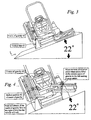
- the grass cutting machine shown in the drawings is of generally conventional construction and the physical layout of the working parts of the machine need not be described in detail.
- the grass cutting machine shown at (10) comprises a chassis (12) supported on forward (14) and rear (16) wheels.
- An operator seat unit (18) is provided on the chassis.
- the machine carries three reel cutting units: a central cutting unit (20) hung beneath the chassis and two front cutting units (left 22 and right 24, as seen by the operator) disposed forwardly of the front wheels (14).
- Each front cutting unit (22,24) is mounted on a lift arm (26).
- each lift arm is mounted on the chassis for rotation about a horizontal axis (28) oriented fore and aft of the machine.
- the lift arm supports the cutting unit through a sleeve (30), the arrangement providing relative rotation of the outward end of the lifting arm and the cutting reel about an axis (32) parallel to the axis (28).
- each cutting unit contains a ground roller (36). This extends parallel to the axis of the cutting reel and is positioned so that in the cutting orientation, engagement of the roller with the ground serves to control the height of cut. In this cutting orientation, the cutter unit floats with respect to the chassis with relative rotation about the parallel axes (28) (32) serving to accommodate ground contours.
- Figures 1 and 2 show the cutting units in a transport position.
- Each lift arm (26) has been lifted to the maximum extent by extension of the corresponding ram.
- the left and right cutting units are locked in a vertical orientation and the overall width of the machine has been significantly reduced..
- An inclinometer (38) is mounted on the chassis, conveniently at a location beneath the operator seat unit (18). This provides an input to the control system of the machine, this input providing a value of the forward-and-backward inclination (that is to say the left-right horizontal direction in Figure 1 ) and the side-to-side inclination (that is to say the lef t- right horizontal direction in Figure 2 ).
- the inclinometer (38) may take the form of a commercially available accelerometer having digital outputs.
- Figure 3 shows a machine positioned on a left to right incline of 22° to the horizontal.
- the machine is shown with the cutting unit that is lower on the slope, raised into the transport position.
- the central cutting unit and the cutting unit which is upper on the slope are both in the grass cutting position, that is to say with the roller of each of those two units in ground contact and the unit floating with respect to the chassis.
- This orientation is chosen as an illustration because it poses a greater risk to stability than the orientation in which all three cutting units are in the cutting position.
- This orientation with one cutting reel in the transport position may occur, for example, where grass is being cut on an incline adjacent a path or other obstacle. Whilst this orientation has been chosen as an illustration, it will be understood that a risk to stability would occur in other orientations.
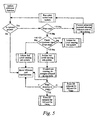
- FIG. 5 A flow diagram for a preferred control process is shown in Figure 5 .
- a measured slope angle is less than a first threshold which in this case is 16°.
- a first threshold which in this case is 16°.
- the same threshold is applied to the slope measured front and back and to the slope measured left and right. It may in some cases be useful to have separate threshold values.
- One way to pre-determine this first threshold value is to measure the actual stability of the machine, that is to say to measure the maximum angle of an incline that can be encountered before stability is lost.
- the first threshold may be chosen to be a proportion, for example approximately 50%, of the maximum stability angle.
- control solenoids are operated allowing selected units to lift or lower and the run cutter control system is allowed to drive the cutting reels conventionally.
- the angles associated with the first, second and third levels are:- Measured inclination % of maximum stability angle Level Up to 15 0 Up to 50% Greater than or equal to 16 0 First Greater than or equal to 18 0 Second Greater than or equal to 22 0 Over 70% Third
- the first level warning sub-system might include a display with real-time slope reading, with a selected colour or temporal variation of the display or an appropriate icon.
- a second level warning sub-system is initiated; this may comprise a different colour or a different temporal variation of the visual display and may further include an appropriate audible alarm. Also, lift, lower and float functions of all three cutter units are blocked. It will be observed that this blocking is the same blocking that occurs in the event of an operator not being present.
- a third level warning sub-system is initiated in which visual and/or audible alarms are varied to convey still greater urgency to the operator. Also, any of the cutters which are running are stopped. Lift, lower and float functions continue to be blocked. A determination is then made as to the sense of any slope in the left right direction, shown in Figure 5 as +X or -X. This determination of the sense of the incline enables the upper of the left and right cutting units to be determined so that, as shown in Figure 4 , the hydraulic ram associated with the upper cutting unit can pulsed to lift that upper cutting unit from the ground.
- the centre unit is also lifted so that the weight of the unit is borne by the chassis, again providing a moment which tends to improve stability.
- each lift arm may be monitored as the associated cutting unit floats. Then, the hydraulic ram associated with the upper cutting unit can be controlled to rotate the lift arm by that precise minimum amount necessary to lift the cutting unit wholly from the ground. In another arrangement, a similar degree of precision can be obtained by monitoring the proportion of the weight of each cutting unit borne by the chassis, for example with strain gauges.
- decisions on whether to lift particular units will be taken in dependence upon the measured value of both the left/right and the fore/aft inclinations. On ground having a substantial slope in both directions, it may for example to lift only the centre unit or only the higher forward unit, if the previously described lifting of both the centre and the higher forward unit would not improve fore/aft stability.
Landscapes
- Life Sciences & Earth Sciences (AREA)
- Environmental Sciences (AREA)
- Engineering & Computer Science (AREA)
- Mechanical Engineering (AREA)
- Harvester Elements (AREA)
Applications Claiming Priority (2)
| Application Number | Priority Date | Filing Date | Title |
|---|---|---|---|
| GB1001902.4A GB2477543B (en) | 2010-02-05 | 2010-02-05 | Machine with ground working elements and method of improving stability |
| PCT/GB2011/050199 WO2011095822A1 (en) | 2010-02-05 | 2011-02-04 | Machine with ground working elements providing improved stability |
Publications (2)
| Publication Number | Publication Date |
|---|---|
| EP2531015A1 EP2531015A1 (en) | 2012-12-12 |
| EP2531015B1 true EP2531015B1 (en) | 2014-01-08 |
Family
ID=42082536
Family Applications (1)
| Application Number | Title | Priority Date | Filing Date |
|---|---|---|---|
| EP11703256.5A Active EP2531015B1 (en) | 2010-02-05 | 2011-02-04 | Machine with ground working elements providing improved stability |
Country Status (7)
| Country | Link |
|---|---|
| US (1) | US9002592B2 (enExample) |
| EP (1) | EP2531015B1 (enExample) |
| JP (1) | JP2013518578A (enExample) |
| CN (1) | CN102753008B (enExample) |
| DK (1) | DK2531015T3 (enExample) |
| GB (1) | GB2477543B (enExample) |
| WO (1) | WO2011095822A1 (enExample) |
Families Citing this family (8)
| Publication number | Priority date | Publication date | Assignee | Title |
|---|---|---|---|---|
| CN105043332A (zh) * | 2015-04-23 | 2015-11-11 | 常州格力博有限公司 | 一种割草机的角度监测系统及其监测方法 |
| JP6972924B2 (ja) * | 2017-10-27 | 2021-11-24 | コベルコ建機株式会社 | 走行ルートガイダンス装置 |
| IT201800006937A1 (it) * | 2018-07-05 | 2020-01-05 | Dispositivo per il controllo del funzionamento di un’apparecchiatura agricola | |
| US11259463B1 (en) * | 2018-10-04 | 2022-03-01 | Harper Industries, Inc. | Slope mower with automatic leveling suspension and system for maintaining vertical orientation of mower body |
| CN109764078B (zh) * | 2019-03-25 | 2024-11-22 | 浙江春风动力股份有限公司 | 一种车辆及其全地形车的主动悬挂装置和减震方法 |
| CN110402670A (zh) * | 2019-08-31 | 2019-11-05 | 黄可 | 一种市政草坪维护设备的控制系统 |
| GB202003489D0 (en) | 2020-03-11 | 2020-04-29 | Agco Int Gmbh | Mower Combination |
| GB202114447D0 (en) * | 2021-10-08 | 2021-11-24 | Agco Int Gmbh | Implement control |
Family Cites Families (19)
| Publication number | Priority date | Publication date | Assignee | Title |
|---|---|---|---|---|
| US3876012A (en) * | 1972-01-18 | 1975-04-08 | Excel Ind | Anti-overturning implement vehicle |
| NL7902576A (en) * | 1979-04-03 | 1979-07-31 | Texas Industries Inc | Tractor drawn rotary mowing machine - has frame arm acting on beam at centre and toothed belt driven bevel gear transmission (OE 15.8.75) |
| US4869054A (en) * | 1986-04-21 | 1989-09-26 | Deweze Corporation | Slope mower with side frames |
| JPH04173003A (ja) * | 1990-11-05 | 1992-06-19 | Kubota Corp | フロントマウント型の乗用芝刈機 |
| US5203149A (en) * | 1991-01-23 | 1993-04-20 | N-R Industries, Inc. | Slope mower |
| JPH08289604A (ja) * | 1995-04-21 | 1996-11-05 | Kochi Pref Gov | 傾斜地走行作業車 |
| JPH0965743A (ja) * | 1995-08-31 | 1997-03-11 | Kubota Corp | 芝刈機 |
| US5711139A (en) | 1996-04-04 | 1998-01-27 | Swanson; Floyd R. | Self-leveling hillside mower with remote control |
| JP2911029B2 (ja) * | 1996-09-10 | 1999-06-23 | 株式会社共栄社 | 草刈機 |
| GB2330757B (en) * | 1997-11-01 | 2002-01-23 | Bomford Turner Ltd | Cutting apparatus |
| GB2346790B (en) * | 1999-02-19 | 2001-11-14 | Spearhead Machinery Ltd | Improvements in mowing head drives |
| US6983583B2 (en) * | 2003-11-21 | 2006-01-10 | Ariens Company | Lawnmower tilt sensor apparatus and method |
| EP2116670B1 (en) * | 2008-01-07 | 2013-11-06 | Hitachi Construction Machinery Co., Ltd | Double arm type work machine |
| US7549243B1 (en) * | 2008-01-15 | 2009-06-23 | Ariens Company | Lawn mower attachment mechanism |
| US8521384B2 (en) * | 2008-01-28 | 2013-08-27 | Textron Innovations Inc. | Turf maintenance vehicle all-wheel drive system |
| JP5168553B2 (ja) * | 2008-03-29 | 2013-03-21 | 株式会社アテックス | ハンド作業機のリヤステップ |
| CN201248261Y (zh) * | 2008-05-04 | 2009-06-03 | 上海创绘机器人科技有限公司 | 智能草坪维护机器人 |
| CN201199324Y (zh) * | 2008-05-16 | 2009-02-25 | 金士正 | 割草机自动停刀控制系统 |
| CN101350137A (zh) | 2008-09-04 | 2009-01-21 | 清华大学 | 货车弯道防侧翻动态检测方法及预警装置 |
-
2010
- 2010-02-05 GB GB1001902.4A patent/GB2477543B/en not_active Expired - Fee Related
-
2011
- 2011-02-04 DK DK11703256.5T patent/DK2531015T3/en active
- 2011-02-04 JP JP2012551690A patent/JP2013518578A/ja active Pending
- 2011-02-04 US US13/576,909 patent/US9002592B2/en active Active
- 2011-02-04 WO PCT/GB2011/050199 patent/WO2011095822A1/en not_active Ceased
- 2011-02-04 EP EP11703256.5A patent/EP2531015B1/en active Active
- 2011-02-04 CN CN201180008456.7A patent/CN102753008B/zh not_active Expired - Fee Related
Also Published As
| Publication number | Publication date |
|---|---|
| DK2531015T3 (en) | 2014-02-24 |
| CN102753008A (zh) | 2012-10-24 |
| GB2477543B (en) | 2013-11-13 |
| CN102753008B (zh) | 2015-11-25 |
| US20120323454A1 (en) | 2012-12-20 |
| EP2531015A1 (en) | 2012-12-12 |
| US9002592B2 (en) | 2015-04-07 |
| GB2477543A (en) | 2011-08-10 |
| JP2013518578A (ja) | 2013-05-23 |
| GB201001902D0 (en) | 2010-03-24 |
| WO2011095822A1 (en) | 2011-08-11 |
Similar Documents
| Publication | Publication Date | Title |
|---|---|---|
| EP2531015B1 (en) | Machine with ground working elements providing improved stability | |
| AU2020203384B2 (en) | Harvester stability monitoring and control | |
| US9956842B2 (en) | System and method for controlling stability of milling machines | |
| EP3695703B1 (en) | Windrower with ground contour sensing system and ground contour sensing method | |
| US9670630B2 (en) | Self-propelled building machine | |
| GB2471134A (en) | Speed sensitive longitudinal load moment control of a working machine | |
| KR101800112B1 (ko) | 보통형 콤바인의 예취부 제어장치 | |
| CN109403398B (zh) | 一种平地机铲刀控制方法以及平地机 | |
| EP2723954B1 (en) | Maximizing scissor lift breakover angle with fixed pothole protection | |
| JP4390873B2 (ja) | 土工用機械の操舵技術を決定するための方法 | |
| DE102022124728A1 (de) | Fräsmaschine mit umkippwarnsystem | |
| CN108307788B (zh) | 收割装置及收割机 | |
| JP2022188496A (ja) | 作業車両 | |
| JP4107592B2 (ja) | 作業機のローリング制御装置 | |
| JP2019088232A (ja) | 苗移植機 | |
| US11041276B2 (en) | Tool exposed status and lockouts | |
| CN106028789B (zh) | 切割机和基部切割组件 | |
| JP5751314B2 (ja) | 乗用型苗移植機 | |
| JP5614400B2 (ja) | 乗用型苗移植機 | |
| JP3916555B2 (ja) | 農作業機のローリング制御装置 | |
| JP2020058381A (ja) | 苗移植機 | |
| JP7360636B1 (ja) | コンバイン | |
| JP2015119676A (ja) | コンバインの刈取昇降制御装置 | |
| JP2020099247A (ja) | コンバイン | |
| JP5761311B2 (ja) | 乗用型苗移植機 |
Legal Events
| Date | Code | Title | Description |
|---|---|---|---|
| PUAI | Public reference made under article 153(3) epc to a published international application that has entered the european phase |
Free format text: ORIGINAL CODE: 0009012 |
|
| 17P | Request for examination filed |
Effective date: 20120727 |
|
| AK | Designated contracting states |
Kind code of ref document: A1 Designated state(s): AL AT BE BG CH CY CZ DE DK EE ES FI FR GB GR HR HU IE IS IT LI LT LU LV MC MK MT NL NO PL PT RO RS SE SI SK SM TR |
|
| DAX | Request for extension of the european patent (deleted) | ||
| GRAP | Despatch of communication of intention to grant a patent |
Free format text: ORIGINAL CODE: EPIDOSNIGR1 |
|
| RIN1 | Information on inventor provided before grant (corrected) |
Inventor name: CLIFFORD, CHRISTIAN, DEAN |
|
| INTG | Intention to grant announced |
Effective date: 20130801 |
|
| GRAS | Grant fee paid |
Free format text: ORIGINAL CODE: EPIDOSNIGR3 |
|
| GRAA | (expected) grant |
Free format text: ORIGINAL CODE: 0009210 |
|
| AK | Designated contracting states |
Kind code of ref document: B1 Designated state(s): AL AT BE BG CH CY CZ DE DK EE ES FI FR GB GR HR HU IE IS IT LI LT LU LV MC MK MT NL NO PL PT RO RS SE SI SK SM TR |
|
| REG | Reference to a national code |
Ref country code: GB Ref legal event code: FG4D |
|
| REG | Reference to a national code |
Ref country code: CH Ref legal event code: EP |
|
| REG | Reference to a national code |
Ref country code: IE Ref legal event code: FG4D |
|
| REG | Reference to a national code |
Ref country code: AT Ref legal event code: REF Ref document number: 648073 Country of ref document: AT Kind code of ref document: T Effective date: 20140215 |
|
| REG | Reference to a national code |
Ref country code: DE Ref legal event code: R096 Ref document number: 602011004587 Country of ref document: DE Effective date: 20140220 |
|
| REG | Reference to a national code |
Ref country code: DK Ref legal event code: T3 Effective date: 20140220 |
|
| REG | Reference to a national code |
Ref country code: SE Ref legal event code: TRGR |
|
| REG | Reference to a national code |
Ref country code: NL Ref legal event code: T3 |
|
| REG | Reference to a national code |
Ref country code: LT Ref legal event code: MG4D |
|
| PG25 | Lapsed in a contracting state [announced via postgrant information from national office to epo] |
Ref country code: NO Free format text: LAPSE BECAUSE OF FAILURE TO SUBMIT A TRANSLATION OF THE DESCRIPTION OR TO PAY THE FEE WITHIN THE PRESCRIBED TIME-LIMIT Effective date: 20140408 Ref country code: LT Free format text: LAPSE BECAUSE OF FAILURE TO SUBMIT A TRANSLATION OF THE DESCRIPTION OR TO PAY THE FEE WITHIN THE PRESCRIBED TIME-LIMIT Effective date: 20140108 Ref country code: IS Free format text: LAPSE BECAUSE OF FAILURE TO SUBMIT A TRANSLATION OF THE DESCRIPTION OR TO PAY THE FEE WITHIN THE PRESCRIBED TIME-LIMIT Effective date: 20140508 |
|
| PG25 | Lapsed in a contracting state [announced via postgrant information from national office to epo] |
Ref country code: CY Free format text: LAPSE BECAUSE OF FAILURE TO SUBMIT A TRANSLATION OF THE DESCRIPTION OR TO PAY THE FEE WITHIN THE PRESCRIBED TIME-LIMIT Effective date: 20140108 Ref country code: FI Free format text: LAPSE BECAUSE OF FAILURE TO SUBMIT A TRANSLATION OF THE DESCRIPTION OR TO PAY THE FEE WITHIN THE PRESCRIBED TIME-LIMIT Effective date: 20140108 Ref country code: PT Free format text: LAPSE BECAUSE OF FAILURE TO SUBMIT A TRANSLATION OF THE DESCRIPTION OR TO PAY THE FEE WITHIN THE PRESCRIBED TIME-LIMIT Effective date: 20140508 Ref country code: ES Free format text: LAPSE BECAUSE OF FAILURE TO SUBMIT A TRANSLATION OF THE DESCRIPTION OR TO PAY THE FEE WITHIN THE PRESCRIBED TIME-LIMIT Effective date: 20140108 |
|
| PG25 | Lapsed in a contracting state [announced via postgrant information from national office to epo] |
Ref country code: BE Free format text: LAPSE BECAUSE OF FAILURE TO SUBMIT A TRANSLATION OF THE DESCRIPTION OR TO PAY THE FEE WITHIN THE PRESCRIBED TIME-LIMIT Effective date: 20140108 Ref country code: LV Free format text: LAPSE BECAUSE OF FAILURE TO SUBMIT A TRANSLATION OF THE DESCRIPTION OR TO PAY THE FEE WITHIN THE PRESCRIBED TIME-LIMIT Effective date: 20140108 Ref country code: RS Free format text: LAPSE BECAUSE OF FAILURE TO SUBMIT A TRANSLATION OF THE DESCRIPTION OR TO PAY THE FEE WITHIN THE PRESCRIBED TIME-LIMIT Effective date: 20140108 Ref country code: HR Free format text: LAPSE BECAUSE OF FAILURE TO SUBMIT A TRANSLATION OF THE DESCRIPTION OR TO PAY THE FEE WITHIN THE PRESCRIBED TIME-LIMIT Effective date: 20140108 |
|
| REG | Reference to a national code |
Ref country code: CH Ref legal event code: PL |
|
| REG | Reference to a national code |
Ref country code: DE Ref legal event code: R097 Ref document number: 602011004587 Country of ref document: DE |
|
| PG25 | Lapsed in a contracting state [announced via postgrant information from national office to epo] |
Ref country code: CH Free format text: LAPSE BECAUSE OF NON-PAYMENT OF DUE FEES Effective date: 20140228 Ref country code: LI Free format text: LAPSE BECAUSE OF NON-PAYMENT OF DUE FEES Effective date: 20140228 Ref country code: RO Free format text: LAPSE BECAUSE OF FAILURE TO SUBMIT A TRANSLATION OF THE DESCRIPTION OR TO PAY THE FEE WITHIN THE PRESCRIBED TIME-LIMIT Effective date: 20140108 Ref country code: EE Free format text: LAPSE BECAUSE OF FAILURE TO SUBMIT A TRANSLATION OF THE DESCRIPTION OR TO PAY THE FEE WITHIN THE PRESCRIBED TIME-LIMIT Effective date: 20140108 Ref country code: MC Free format text: LAPSE BECAUSE OF FAILURE TO SUBMIT A TRANSLATION OF THE DESCRIPTION OR TO PAY THE FEE WITHIN THE PRESCRIBED TIME-LIMIT Effective date: 20140108 |
|
| PLBE | No opposition filed within time limit |
Free format text: ORIGINAL CODE: 0009261 |
|
| STAA | Information on the status of an ep patent application or granted ep patent |
Free format text: STATUS: NO OPPOSITION FILED WITHIN TIME LIMIT |
|
| PG25 | Lapsed in a contracting state [announced via postgrant information from national office to epo] |
Ref country code: SK Free format text: LAPSE BECAUSE OF FAILURE TO SUBMIT A TRANSLATION OF THE DESCRIPTION OR TO PAY THE FEE WITHIN THE PRESCRIBED TIME-LIMIT Effective date: 20140108 Ref country code: PL Free format text: LAPSE BECAUSE OF FAILURE TO SUBMIT A TRANSLATION OF THE DESCRIPTION OR TO PAY THE FEE WITHIN THE PRESCRIBED TIME-LIMIT Effective date: 20140108 |
|
| REG | Reference to a national code |
Ref country code: IE Ref legal event code: MM4A |
|
| 26N | No opposition filed |
Effective date: 20141009 |
|
| REG | Reference to a national code |
Ref country code: DE Ref legal event code: R097 Ref document number: 602011004587 Country of ref document: DE Effective date: 20141009 |
|
| PG25 | Lapsed in a contracting state [announced via postgrant information from national office to epo] |
Ref country code: IE Free format text: LAPSE BECAUSE OF NON-PAYMENT OF DUE FEES Effective date: 20140204 |
|
| REG | Reference to a national code |
Ref country code: FR Ref legal event code: PLFP Year of fee payment: 5 |
|
| PG25 | Lapsed in a contracting state [announced via postgrant information from national office to epo] |
Ref country code: SI Free format text: LAPSE BECAUSE OF FAILURE TO SUBMIT A TRANSLATION OF THE DESCRIPTION OR TO PAY THE FEE WITHIN THE PRESCRIBED TIME-LIMIT Effective date: 20140108 |
|
| REG | Reference to a national code |
Ref country code: FR Ref legal event code: PLFP Year of fee payment: 6 |
|
| PG25 | Lapsed in a contracting state [announced via postgrant information from national office to epo] |
Ref country code: MT Free format text: LAPSE BECAUSE OF FAILURE TO SUBMIT A TRANSLATION OF THE DESCRIPTION OR TO PAY THE FEE WITHIN THE PRESCRIBED TIME-LIMIT Effective date: 20140108 |
|
| PG25 | Lapsed in a contracting state [announced via postgrant information from national office to epo] |
Ref country code: SM Free format text: LAPSE BECAUSE OF FAILURE TO SUBMIT A TRANSLATION OF THE DESCRIPTION OR TO PAY THE FEE WITHIN THE PRESCRIBED TIME-LIMIT Effective date: 20140108 |
|
| PGFP | Annual fee paid to national office [announced via postgrant information from national office to epo] |
Ref country code: CZ Payment date: 20160108 Year of fee payment: 6 Ref country code: IT Payment date: 20160224 Year of fee payment: 6 Ref country code: DK Payment date: 20160226 Year of fee payment: 6 |
|
| PGFP | Annual fee paid to national office [announced via postgrant information from national office to epo] |
Ref country code: AT Payment date: 20160225 Year of fee payment: 6 Ref country code: SE Payment date: 20160226 Year of fee payment: 6 |
|
| PG25 | Lapsed in a contracting state [announced via postgrant information from national office to epo] |
Ref country code: BG Free format text: LAPSE BECAUSE OF FAILURE TO SUBMIT A TRANSLATION OF THE DESCRIPTION OR TO PAY THE FEE WITHIN THE PRESCRIBED TIME-LIMIT Effective date: 20140108 Ref country code: GR Free format text: LAPSE BECAUSE OF FAILURE TO SUBMIT A TRANSLATION OF THE DESCRIPTION OR TO PAY THE FEE WITHIN THE PRESCRIBED TIME-LIMIT Effective date: 20140409 |
|
| PG25 | Lapsed in a contracting state [announced via postgrant information from national office to epo] |
Ref country code: HU Free format text: LAPSE BECAUSE OF FAILURE TO SUBMIT A TRANSLATION OF THE DESCRIPTION OR TO PAY THE FEE WITHIN THE PRESCRIBED TIME-LIMIT; INVALID AB INITIO Effective date: 20110204 Ref country code: TR Free format text: LAPSE BECAUSE OF FAILURE TO SUBMIT A TRANSLATION OF THE DESCRIPTION OR TO PAY THE FEE WITHIN THE PRESCRIBED TIME-LIMIT Effective date: 20140108 Ref country code: LU Free format text: LAPSE BECAUSE OF NON-PAYMENT OF DUE FEES Effective date: 20140204 |
|
| REG | Reference to a national code |
Ref country code: FR Ref legal event code: PLFP Year of fee payment: 7 |
|
| REG | Reference to a national code |
Ref country code: DK Ref legal event code: EBP Effective date: 20170228 |
|
| REG | Reference to a national code |
Ref country code: SE Ref legal event code: EUG |
|
| REG | Reference to a national code |
Ref country code: AT Ref legal event code: MM01 Ref document number: 648073 Country of ref document: AT Kind code of ref document: T Effective date: 20170204 |
|
| PG25 | Lapsed in a contracting state [announced via postgrant information from national office to epo] |
Ref country code: AT Free format text: LAPSE BECAUSE OF NON-PAYMENT OF DUE FEES Effective date: 20170204 Ref country code: CZ Free format text: LAPSE BECAUSE OF NON-PAYMENT OF DUE FEES Effective date: 20170204 |
|
| PG25 | Lapsed in a contracting state [announced via postgrant information from national office to epo] |
Ref country code: SE Free format text: LAPSE BECAUSE OF NON-PAYMENT OF DUE FEES Effective date: 20170205 |
|
| PG25 | Lapsed in a contracting state [announced via postgrant information from national office to epo] |
Ref country code: DK Free format text: LAPSE BECAUSE OF NON-PAYMENT OF DUE FEES Effective date: 20170228 |
|
| REG | Reference to a national code |
Ref country code: FR Ref legal event code: PLFP Year of fee payment: 8 |
|
| PG25 | Lapsed in a contracting state [announced via postgrant information from national office to epo] |
Ref country code: IT Free format text: LAPSE BECAUSE OF NON-PAYMENT OF DUE FEES Effective date: 20170204 |
|
| PG25 | Lapsed in a contracting state [announced via postgrant information from national office to epo] |
Ref country code: MK Free format text: LAPSE BECAUSE OF FAILURE TO SUBMIT A TRANSLATION OF THE DESCRIPTION OR TO PAY THE FEE WITHIN THE PRESCRIBED TIME-LIMIT Effective date: 20140108 |
|
| PG25 | Lapsed in a contracting state [announced via postgrant information from national office to epo] |
Ref country code: AL Free format text: LAPSE BECAUSE OF FAILURE TO SUBMIT A TRANSLATION OF THE DESCRIPTION OR TO PAY THE FEE WITHIN THE PRESCRIBED TIME-LIMIT Effective date: 20140108 |
|
| P01 | Opt-out of the competence of the unified patent court (upc) registered |
Effective date: 20230529 |
|
| PGFP | Annual fee paid to national office [announced via postgrant information from national office to epo] |
Ref country code: NL Payment date: 20250227 Year of fee payment: 15 |
|
| PGFP | Annual fee paid to national office [announced via postgrant information from national office to epo] |
Ref country code: DE Payment date: 20250227 Year of fee payment: 15 |
|
| PGFP | Annual fee paid to national office [announced via postgrant information from national office to epo] |
Ref country code: FR Payment date: 20250225 Year of fee payment: 15 |
|
| PGFP | Annual fee paid to national office [announced via postgrant information from national office to epo] |
Ref country code: GB Payment date: 20250227 Year of fee payment: 15 |