EP2525995B1 - Beschlagsystem für einen fahrzeugsitz - Google Patents
Beschlagsystem für einen fahrzeugsitz Download PDFInfo
- Publication number
- EP2525995B1 EP2525995B1 EP11700799.7A EP11700799A EP2525995B1 EP 2525995 B1 EP2525995 B1 EP 2525995B1 EP 11700799 A EP11700799 A EP 11700799A EP 2525995 B1 EP2525995 B1 EP 2525995B1
- Authority
- EP
- European Patent Office
- Prior art keywords
- fitting
- driver
- shaft
- axially
- vehicle seat
- Prior art date
- Legal status (The legal status is an assumption and is not a legal conclusion. Google has not performed a legal analysis and makes no representation as to the accuracy of the status listed.)
- Active
Links
- 210000002105 tongue Anatomy 0.000 claims description 5
- 230000003993 interaction Effects 0.000 claims description 4
- 230000033001 locomotion Effects 0.000 claims description 4
- 238000005096 rolling process Methods 0.000 claims description 3
- 238000006073 displacement reaction Methods 0.000 description 4
- 229910000639 Spring steel Inorganic materials 0.000 description 2
- 230000005540 biological transmission Effects 0.000 description 2
- 239000000463 material Substances 0.000 description 2
- 239000011324 bead Substances 0.000 description 1
- 230000008878 coupling Effects 0.000 description 1
- 238000010168 coupling process Methods 0.000 description 1
- 238000005859 coupling reaction Methods 0.000 description 1
- 230000001419 dependent effect Effects 0.000 description 1
- 230000002349 favourable effect Effects 0.000 description 1
- IHQKEDIOMGYHEB-UHFFFAOYSA-M sodium dimethylarsinate Chemical class [Na+].C[As](C)([O-])=O IHQKEDIOMGYHEB-UHFFFAOYSA-M 0.000 description 1
- 230000009466 transformation Effects 0.000 description 1
- 238000000844 transformation Methods 0.000 description 1
- 230000007704 transition Effects 0.000 description 1
Images

Classifications
-
- B—PERFORMING OPERATIONS; TRANSPORTING
- B60—VEHICLES IN GENERAL
- B60N—SEATS SPECIALLY ADAPTED FOR VEHICLES; VEHICLE PASSENGER ACCOMMODATION NOT OTHERWISE PROVIDED FOR
- B60N2/00—Seats specially adapted for vehicles; Arrangement or mounting of seats in vehicles
- B60N2/02—Seats specially adapted for vehicles; Arrangement or mounting of seats in vehicles the seat or part thereof being movable, e.g. adjustable
- B60N2/22—Seats specially adapted for vehicles; Arrangement or mounting of seats in vehicles the seat or part thereof being movable, e.g. adjustable the back-rest being adjustable
- B60N2/225—Seats specially adapted for vehicles; Arrangement or mounting of seats in vehicles the seat or part thereof being movable, e.g. adjustable the back-rest being adjustable by cycloidal or planetary mechanisms
-
- B—PERFORMING OPERATIONS; TRANSPORTING
- B60—VEHICLES IN GENERAL
- B60N—SEATS SPECIALLY ADAPTED FOR VEHICLES; VEHICLE PASSENGER ACCOMMODATION NOT OTHERWISE PROVIDED FOR
- B60N2/00—Seats specially adapted for vehicles; Arrangement or mounting of seats in vehicles
- B60N2/68—Seat frames
- B60N2/682—Joining means
-
- B—PERFORMING OPERATIONS; TRANSPORTING
- B60—VEHICLES IN GENERAL
- B60N—SEATS SPECIALLY ADAPTED FOR VEHICLES; VEHICLE PASSENGER ACCOMMODATION NOT OTHERWISE PROVIDED FOR
- B60N2/00—Seats specially adapted for vehicles; Arrangement or mounting of seats in vehicles
- B60N2/02—Seats specially adapted for vehicles; Arrangement or mounting of seats in vehicles the seat or part thereof being movable, e.g. adjustable
- B60N2/20—Seats specially adapted for vehicles; Arrangement or mounting of seats in vehicles the seat or part thereof being movable, e.g. adjustable the back-rest being tiltable, e.g. to permit easy access
-
- B—PERFORMING OPERATIONS; TRANSPORTING
- B60—VEHICLES IN GENERAL
- B60N—SEATS SPECIALLY ADAPTED FOR VEHICLES; VEHICLE PASSENGER ACCOMMODATION NOT OTHERWISE PROVIDED FOR
- B60N2/00—Seats specially adapted for vehicles; Arrangement or mounting of seats in vehicles
- B60N2/02—Seats specially adapted for vehicles; Arrangement or mounting of seats in vehicles the seat or part thereof being movable, e.g. adjustable
- B60N2/22—Seats specially adapted for vehicles; Arrangement or mounting of seats in vehicles the seat or part thereof being movable, e.g. adjustable the back-rest being adjustable
- B60N2/225—Seats specially adapted for vehicles; Arrangement or mounting of seats in vehicles the seat or part thereof being movable, e.g. adjustable the back-rest being adjustable by cycloidal or planetary mechanisms
- B60N2/2252—Seats specially adapted for vehicles; Arrangement or mounting of seats in vehicles the seat or part thereof being movable, e.g. adjustable the back-rest being adjustable by cycloidal or planetary mechanisms in which the central axis of the gearing lies inside the periphery of an orbital gear, e.g. one gear without sun gear
-
- B—PERFORMING OPERATIONS; TRANSPORTING
- B60—VEHICLES IN GENERAL
- B60N—SEATS SPECIALLY ADAPTED FOR VEHICLES; VEHICLE PASSENGER ACCOMMODATION NOT OTHERWISE PROVIDED FOR
- B60N2/00—Seats specially adapted for vehicles; Arrangement or mounting of seats in vehicles
- B60N2/02—Seats specially adapted for vehicles; Arrangement or mounting of seats in vehicles the seat or part thereof being movable, e.g. adjustable
- B60N2/22—Seats specially adapted for vehicles; Arrangement or mounting of seats in vehicles the seat or part thereof being movable, e.g. adjustable the back-rest being adjustable
- B60N2/235—Seats specially adapted for vehicles; Arrangement or mounting of seats in vehicles the seat or part thereof being movable, e.g. adjustable the back-rest being adjustable by gear-pawl type mechanisms
- B60N2/2356—Seats specially adapted for vehicles; Arrangement or mounting of seats in vehicles the seat or part thereof being movable, e.g. adjustable the back-rest being adjustable by gear-pawl type mechanisms with internal pawls
-
- B—PERFORMING OPERATIONS; TRANSPORTING
- B60—VEHICLES IN GENERAL
- B60N—SEATS SPECIALLY ADAPTED FOR VEHICLES; VEHICLE PASSENGER ACCOMMODATION NOT OTHERWISE PROVIDED FOR
- B60N2/00—Seats specially adapted for vehicles; Arrangement or mounting of seats in vehicles
- B60N2/68—Seat frames
-
- B—PERFORMING OPERATIONS; TRANSPORTING
- B60—VEHICLES IN GENERAL
- B60N—SEATS SPECIALLY ADAPTED FOR VEHICLES; VEHICLE PASSENGER ACCOMMODATION NOT OTHERWISE PROVIDED FOR
- B60N2205/00—General mechanical or structural details
- B60N2205/50—Interlocking shaft arrangements transmitting movement between hinge mechanisms on both sides of a seat
-
- F—MECHANICAL ENGINEERING; LIGHTING; HEATING; WEAPONS; BLASTING
- F16—ENGINEERING ELEMENTS AND UNITS; GENERAL MEASURES FOR PRODUCING AND MAINTAINING EFFECTIVE FUNCTIONING OF MACHINES OR INSTALLATIONS; THERMAL INSULATION IN GENERAL
- F16B—DEVICES FOR FASTENING OR SECURING CONSTRUCTIONAL ELEMENTS OR MACHINE PARTS TOGETHER, e.g. NAILS, BOLTS, CIRCLIPS, CLAMPS, CLIPS OR WEDGES; JOINTS OR JOINTING
- F16B21/00—Means for preventing relative axial movement of a pin, spigot, shaft or the like and a member surrounding it; Stud-and-socket releasable fastenings
- F16B21/10—Means for preventing relative axial movement of a pin, spigot, shaft or the like and a member surrounding it; Stud-and-socket releasable fastenings by separate parts
- F16B21/20—Means for preventing relative axial movement of a pin, spigot, shaft or the like and a member surrounding it; Stud-and-socket releasable fastenings by separate parts for bolts or shafts without holes, grooves, or notches for locking members
Definitions
- the invention relates to a fitting system for a vehicle seat having the features of the preamble of claim 1.
- a fitting system of this kind is from the DE 103 52 630 B4 known.
- the wave is applied with a bead on the inside of the fitting, while on the outside of the fitting rests a pushed onto the shaft quick fastener. The shaft is thereby relative to the fitting immovable.
- a coupling between two waves reveals the EP 0 917 984 A2
- a shaft end of the first shaft has a hexagonally shaped receptacle into which the end of the second shaft designed as a hexagonal ball head is inserted.
- the ball head allows a tilting movement relative to the receptacle and thus an angular tolerance compensation between the two shafts.
- the hexagon geometries are used for positive torque transmission.
- the invention is based on the object to improve a fitting system of the type mentioned, in particular to avoid special transformations of the shaft. This object is achieved by a fitting system with the features of claim 1.
- Advantageous embodiments are the subject of the dependent claims.
- the quick fastener on the one hand and the driver and / or its securing element on the other hand are separate components (separately formed components). They can therefore consist of different materials, such as spring steel on the one hand and plastic on the other hand, so that the most favorable properties of the different materials are combined.
- the quick fastener By the quick fastener is connected to the driver and / or its securing element, an axial securing of the shaft is achieved in both axial directions, without special deformations of the shaft are necessary.
- In one direction acts the quick fastener due to the system to the fitting as an axial securing of the shaft, in the opposite direction due to the connection with the driver or its securing element.
- the quick fastener thus ensures the interaction of shaft and driver axially in both directions. Which of the two components of the quick fastener is directly connected depends on the orientation of the driver or the fitting. Indirectly, the quick fastener is connected to the driver in both orientations.
- connection between the quick fastener and the driver or its securing element can be made simple. This is achieved by at least one axially projecting fingers for positive cooperation, preferably by means of hooks, in particular lugs for clipping.
- the invention can be used both with geared fittings as well as with detent fittings. It can be used as Lehneneinsteller a vehicle seat or elsewhere in the vehicle seat.
- the quick fastener may also interact with a subassembly other than a fitting.
- a vehicle seat 1 for a motor vehicle has a seat part 3 and a backrest 4 that is adjustable in its inclination relative to the seat part 3.
- a shaft 7 is rotated, which is arranged horizontally in the transition region between the seat part 3 and backrest 4.
- the shaft 7 rotatably engages in a fitting 10 a.
- the shaft 7 defines the used directional information of a cylindrical coordinate system.
- the shaft 7 and the two fittings 10 are components of a fitting system for tilt adjustment of the backrest. 4
- Each fitting 10 has a first fitting part 11 and a second fitting part 12, which are rotatable relative to each other.
- one of the two fitting parts 11 and 12 of the back 4 is assigned and connected to the structure, while the other of the two fitting parts 11 and 12 associated with the seat part 3 and is firmly connected to the structure.
- the relative rotation of the two fitting parts 11 and 12 causes the inclination adjustment of the backrest. 4
- a driver 21 is rotatably mounted.
- the driver 21 is centrally provided with a bore for receiving the shaft 7.
- the profile of the bore is suitable for the profile of the shaft 7, in this case a splined shaft profile formed.
- the shaft 7 and the driver are preferably non-rotatable with each other coupled. However, it can also be provided in the circumferential direction an idle, so that the shaft 7 and the driver 21 are coupled to driving.
- the driver 21 preferably has on one side a cover plate or a flange, by means of which it rests on the outside of one of the two fitting parts 11 and 12. On the outside of the other of the two fitting parts 11 and 12 by a - for example, annular, preferably clipped - securing element 43 axially secured.
- two basic types are conceivable.
- the fitting 10 is designed as a geared fitting, in which the first fitting part 11 and the second fitting part 12 are connected to each other by means of a gear for adjusting and locking, more precisely by means of a - present self-locking - eccentric orbit gear, as for example in the DE 44 36 101 A1 is described.
- a gear for adjusting and locking more precisely by means of a - present self-locking - eccentric orbit gear, as for example in the DE 44 36 101 A1 is described.
- an externally toothed gear is formed on the second fitting part 12, and an internally toothed ring gear is formed on the first fitting part 11, which mesh with one another.
- the diameter of the top circle of the external toothing of the toothed wheel is smaller by at least one tooth height than the diameter of the root circle of the internal toothing of the toothed ring.
- a corresponding difference in the number of teeth of gear and ring gear of at least one tooth allows a rolling movement of the ring gear on the gear.
- One of the two fitting parts 11 and 12 has a collar, which preferably serves as a bearing for the driver 21.
- On the collar two wedge segments are supported (with their curved inner surfaces), which (with their curved outer surfaces and preferably by means of a plain bearing bush) the other of the two fitting parts 11 and 12 store.
- the driver 21 has a catching segment with play between the narrow sides of the wedge segments.
- the mutually facing broad sides of the wedge segments each receive an end finger of a spring, which presses apart the wedge segments in the circumferential direction.
- an eccentric By the wedge segments 27 (and the spring) an eccentric is defined, which pushes the gear at an engagement point in the ring gear in extension of the direction of eccentricity.
- a torque is first transmitted to the driver 21 and then by means of the driver segment on the eccentric so defined, which slides along the plain bearing sleeve with displacement of the direction of eccentricity and thus under displacement of the intervention of the Gear in the ring gear, which is a tumbling rolling motion, ie as relative rotation with superimposed wobble.
- the inclination of the backrest 4 is continuously adjustable by this drive of the fittings 10 between several positions of use.
- a third fitting part is provided, which on the one hand firmly connected to the structure of the backrest 4 and on the other hand pivotally mounted relative to the non-seat part 3 associated fitting 11 or 12 and is releasably locked thereto.
- This design allows a free pivoting of the back 4 to facilitate access to a rear row of seats, without the set inclination of the backrest 4 is changed.
- the fitting 10 is designed as a latching fitting, in which the first fitting part 11 and the second fitting part 12 are locked together, as for example in the DE 10 2006 015 560 B3 is described.
- the second fitting part 12 has guide segments which, with straight guide surfaces in pairs, each guide a bolt laterally in the radial direction.
- the bars are provided at their radially outer end with a toothing, which engage with a ring gear of the first fitting part 11 formed as a ring gear can engage.
- the guide segments abut each with a curved bearing surface on the sprocket of the first fitting part 11, whereby the two fitting parts 11 and 12 store each other.
- On the driver 21 is rotatably or at least coupled to driving an eccentric, which is arranged in the defined between the fitting parts 11 and 12 space.
- a spring arrangement acts on the eccentric, which acts on the radially movable latch and these acted so that they are pressed radially outward to collapse in the sprocket.
- a control disk which is preferably non-rotatably mounted on the eccentric or on the driver 21, cooperates with the latches to a rotation (by a few degrees) of the driver 21 - and thus driven eccentric and the control disk - against the force of the spring assembly the retrieve latch, ie to pull radially outward from the sprocket, whereby the fitting 10 is unlocked and the two fitting parts 11 and 12 are rotatable relative to each other.
- the inclination of the back 4 is characterized adjustable between several, suitable for sitting use positions.
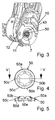
- the Quick fastener 50 In order to prevent displacement of the shaft 7 relative to the fitting 10 - and thus to the driver 21 - which is ensured by means of the system of the quick-fastener 50 on the fitting only in one of two possible directions, is the Quick fastener 50 according to the invention connected to the driver 21 or its securing element 43, depending on which side of the fitting 10 to the outer end of the shaft 7 has.
- the Schnellbefestiger 50 ensures the interaction of shaft 7 and driver 21 axially in both directions.
- the quick-fastener 50 has at least one, preferably a plurality of (in the present case six) fingers 50c which, distributed in the circumferential direction, project axially from the main body 50a and point towards the fitting 10.
- the fingers 50c interact positively with the driver 21 or securing element 43. They may for example be formed as a hook or the like, which engage behind the driver 21 or the securing element 43, for example, with a radially inwardly facing nose 50 d engage in a circumferential groove thereof. Between the fingers 50c are preferably alternately further (present six) axially projecting segments 50e provided, which can facilitate the positioning of the Schnellbefestigers 50 relative to the driver 21.
Landscapes
- Engineering & Computer Science (AREA)
- Aviation & Aerospace Engineering (AREA)
- Transportation (AREA)
- Mechanical Engineering (AREA)
- Chairs For Special Purposes, Such As Reclining Chairs (AREA)
- Seats For Vehicles (AREA)
Description
- Die Erfindung betrifft ein Beschlagsystem für einen Fahrzeugsitz mit den Merkmalen des Oberbegriffs des Anspruches 1.
- Ein Beschlagsystem dieser Art ist aus der
DE 103 52 630 B4 bekannt. Bei einem der beiden Beschläge liegt die Welle mit einem Wulst an der Innenseite des Beschlags an, während an der Außenseite des Beschlags ein auf die Welle geschobener Schnellbefestiger anliegt. Die Welle ist dadurch relativ zum Beschlag unverschieblich. - Aus der
DE 100 21 404 A1 ist eine an einer Welle eines Beschlags befestigte Sicherungsscheibe bekannt, die Federlaschen aufweist, welche in axialer Richtung von einem Basisbereich der Sicherungsscheibe abgekröpft sind und zur federnden Anlage an ein zweites Bauelement ausgebildet sind. Die Federlaschen dienen dem Ausgleich von radialem Spiel zwischen der Welle und dem zweiten Bauelement, nicht jedoch einer axialen Sicherung der Welle durch Formschluss. - Eine Kupplung zwischen zwei Wellen offenbart die
EP 0 917 984 A2 . Ein Wellenende der ersten Welle weist eine sechseckig ausgeformte Aufnahme auf, in die das als Sechskant-Kugelkopf ausgebildete Ende der zweiten Welle eingeführt ist. Der Kugelkopf ermöglicht eine Kippbewegung relativ zu der Aufnahme und somit einen Winkeltoleranzausgleich zwischen den beiden Wellen. Die Sechseck-Geometrien dienen der formschlüssigen Drehmomentübertragung. - Der Erfindung liegt die Aufgabe zu Grunde, ein Beschlagsystem der eingangs genannten Art zu verbessern, insbesondere spezielle Umformungen der Welle zu vermeiden. Diese Aufgabe wird erfindungsgemäß durch ein Beschlagsystem mit den Merkmalen des Anspruches 1 gelöst. Vorteilhafte Ausgestaltungen sind Gegenstand der Unteransprüche.
- Der Schnellbefestiger einerseits und der Mitnehmer und/oder dessen Sicherungselement andererseits sind separate Bauteile (separat ausgebildete Bauteile). Sie können daher aus verschiedenen Materialien bestehen, beispielsweise Federstahl einerseits und Kunststoff andererseits, so dass die jeweils günstigsten Eigenschaften der verschiedenen Materialien kombiniert werden.
- Indem der Schnellbefestiger mit dem Mitnehmer und/oder dessen Sicherungselement verbunden ist, wird eine axiale Sicherung der Welle in beide axiale Richtungen erreicht, ohne dass spezielle Umformungen der Welle notwendig sind. In eine Richtung wirkt der Schnellbefestiger aufgrund der Anlage an den Beschlag als axiale Sicherung der Welle, in der entgegengesetzten Richtung aufgrund der Verbindung mit dem Mitnehmer oder dessen Sicherungselement. Der Schnellbefestiger sichert also das Zusammenwirken von Welle und Mitnehmer axial in beide Richtungen. Mit welchem der beiden Bauteile der Schnellbefestiger direkt verbunden ist, hängt von der Orientierung des Mitnehmers oder des Beschlags ab. Indirekt ist der Schnellbefestiger bei beiden Orientierungen mit dem Mitnehmer verbunden.
- Da die Welle und der Mitnehmer in Umfangsrichtung drehfest verbunden sind oder mit einem Leerweg auf Mitnahme gekoppelt sind, kann die Verbindung zwischen dem Schnellbefestiger und dem Mitnehmer oder dessen Sicherungselement einfach gestaltet werden. Dies wird erreicht, durch mindestens einen axial abstehenden Finger zum formschlüssigen Zusammenwirken, vorzugsweise mittels Haken, insbesondere Nasen zum Clipsen.
- Die Erfindung kann sowohl mit Getriebebeschlägen als auch mit Rastbeschlägen verwendet werden. Sie kann als Lehneneinsteller eines Fahrzeugsitzes oder an anderer Stelle des Fahrzeugsitzes verwendet werden. Der Schnellbefestiger kann auch mit einer anderen Baugruppe als einem Beschlag zusammenwirken.
- Im Folgenden ist die Erfindung anhand eines in der Zeichnung dargestellten Ausführungsbeispiels näher erläutert. Es zeigen
- Fig. 1
- eine perspektivische Ansicht des Ausführungsbeispiels vor der Montage des Schnellbefestigers,
- Fig. 2
- eine perspektivische Ansicht des Schnellbefestigers,
- Fig. 3
- eine perspektivische Ansicht des Ausführungsbeispiels nach der Montage des Schnellbefestigers,
- Fig. 4
- eine Draufsicht auf den Schnellbefestiger,
- Fig. 5
- einen Schnitt durch den Schnellbefestiger entlang der Linie V-V in
Fig. 4 , und - Fig. 6
- eine schematische Darstellung eines Fahrzeugsitzes.
- Ein Fahrzeugsitz 1 für ein Kraftfahrzeug weist ein Sitzteil 3 und eine relativ zum Sitzteil 3 in ihrer Neigung einstellbare Lehne 4 auf. Zur Neigungseinstellung der Lehne 4 wird manuell, beispielsweise mittels eines Handrades 5, oder motorisch, beispielsweise mittels eines Elektromotors, eine Welle 7 gedreht, welche horizontal im Übergangsbereich zwischen Sitzteil 3 und Lehne 4 angeordnet ist. Auf beiden Seiten des Fahrzeugsitzes 1 greift die Welle 7 drehfest in einen Beschlag 10 ein. Die Welle 7 definiert die verwendeten Richtungsangaben eines Zylinderkoordinatensystems. Die Welle 7 und die beiden Beschläge 10 sind Bestandteile eines Beschlagsystems zur Neigungseinstellung der Lehne 4.
- Jeder Beschlag 10 weist ein erstes Beschlagteil 11 und ein zweites Beschlagteil 12 auf, welche relativ zueinander verdrehbar sind. Mit der Montage des Beschlags 10 ist eines der beiden Beschlagteile 11 und 12 der Lehne 4 zugeordnet und mit deren Struktur verbunden, während das andere der beiden Beschlagteile 11 und 12 dem Sitzteil 3 zugeordnet und fest mit dessen Struktur verbunden ist. Das relative Verdrehen der beiden Beschlagteile 11 und 12 bewirkt die Neigungseinstellung der Lehne 4.
- Im Zentrum des Beschlags 10 ist drehbar ein Mitnehmer 21 gelagert. Der Mitnehmer 21 ist zentral mit einer Bohrung zur Aufnahme der Welle 7 versehen. Das Profil der Bohrung ist passend zum Profil der Welle 7, vorliegend einem Keilwellenprofil, ausgebildet. Die Welle 7 und der Mitnehmer sind vorzugsweise drehfest miteinander gekoppelt. Es kann jedoch auch in Umfangsrichtung ein Leerweg vorgesehen sein, so dass die Welle 7 und der Mitnehmer 21 auf Mitnahme gekoppelt sind. Der Mitnehmer 21 weist vorzugsweise auf einer Seite eine Abdeckscheibe oder einen Flansch auf, mittels dessen er auf der Außenseite des einen der beiden Beschlagteile 11 und 12 anliegt. Auf der Außenseite des anderen der beiden Beschlagteile 11 und 12 durch ein - beispieslweise ringförmiges, vorzugsweise aufgeclipstes - Sicherungselement 43 axial gesichert. Hinsichtlich des weiteren inneren Aufbaus des Beschlags 10 sind zwei Grundtypen denkbar.
- Gemäß einem ersten Grundtyp ist der Beschlag 10 als Getriebebeschlag ausgebildet, bei welchem das erste Beschlagteil 11 und das zweite Beschlagteil 12 mittels eines Getriebes zum Verstellen und Feststellen miteinander verbunden sind, genauer gesagt mittels eines - vorliegend selbsthemmenden - Exzenterumlaufgetriebes, wie es beispielsweise in der
DE 44 36 101 A1 beschrieben ist. Zur Ausbildung des Getriebes ist am zweiten Beschlagteil 12 ein außenverzahntes Zahnrad und am ersten Beschlagteil 11 ein innenverzahnter Zahnkranz ausgebildet, welche miteinander kämmen. Der Durchmesser des Kopfkreises der Außenverzahnung des Zahnrads ist um wenigstens eine Zahnhöhe kleiner als der Durchmesser des Fußkreises der Innenverzahnung des Zahnkranzes. Ein entsprechender Unterschied der Zähneanzahl von Zahnrad und Zahnkranz von wenigstens einem Zahn ermöglicht eine Abwälzbewegung des Zahnkranzes am Zahnrad. Eines der beiden Beschlagteile 11 und 12 weist einen Kragen auf, der vorzugsweise als Lager für den Mitnehmer 21 dient. Auf dem Kragen sind zwei Keilsegmente (mit ihren gekrümmten Innenflächen) abgestützt, die (mit ihren gekrümmten Außenflächen und vorzugsweise mittels einer Gleitlagerbuchse) das andere der beiden Beschlagteile 11 und 12 lagern. Der Mitnehmer 21 weist ein mit Spiel zwischen die Schmalseiten der Keilsegmente fassendes Mitnehmersegment auf. Die einander zugekehrten Breitseiten der Keilsegmente nehmen jeweils einen Endfinger einer Feder auf, welche die Keilsegmente in Umfangsrichtung auseinanderdrückt. - Durch die Keilsegmente 27 (und die Feder) wird ein Exzenter definiert, welcher in Verlängerung der Richtung der Exzentrizität das Zahnrad an einer Eingriffsstelle in den Zahnkranz drückt. Bei einem Antrieb durch die sich (mehrfach) drehende Welle 7 wird ein Drehmoment zunächst auf den Mitnehmer 21 und mittels des Mitnehmersegments dann auf den so definierten Exzenter übertragen, welcher entlang der Gleitlagerbuchse gleitet unter Verlagerung der Richtung der Exzentrizität und damit unter Verlagerung der Eingriffsstelle des Zahnrades im Zahnkranz, was sich als taumelnde Abwälzbewegung darstellt, d.h. als Relativdrehung mit überlagerter Taumelbewegung. Die Neigung der Lehne 4 ist durch diesen Antrieb der Beschläge 10 zwischen mehreren Gebrauchsstellungen stufenlos einstellbar.
- Optional ist ein drittes Beschlagteil vorgesehen, welches einerseits fest mit der Struktur der Lehne 4 verbunden und andererseits relativ zu dem der nicht dem Sitzteil 3 zugeordneten Beschlagteil 11 oder 12 schwenkbar gelagert und mit diesem lösbar verriegelt ist. Diese Ausbildung erlaubt ein Freischwenken der Lehne 4 zur Erleichterung des Zugangs zu einer hinteren Sitzreihe, ohne dass die eingestellte Neigung der Lehne 4 geändert wird.
- Gemäß einem zweiten Grundtyp ist der Beschlag 10 als Rastbeschlag ausgebildet, bei welchem das erste Beschlagteil 11 und das zweite Beschlagteil 12 miteinander verriegelbar sind, wie es beispielsweise in der
DE 10 2006 015 560 B3 beschrieben ist. - Das zweite Beschlagteil 12 weist Führungssegmente auf, welche mit geraden Führungsflächen paarweise jeweils einen Riegel seitlich in radialer Richtung führen. Die Riegel sind an ihrem radial außen liegenden Ende mit einer Verzahnung versehen, die mit einem Zahnkranz des als Hohlrad ausgebildeten ersten Beschlagteils 11 in Eingriff gelangen (einfallen) kann. Wenn der Zahnkranz und die Riegel zusammenwirken, ist der Beschlag 10 verriegelt. Die Führungssegmente liegen mit jeweils einer gebogenen Lagerfläche am Zahnkranz des ersten Beschlagteils 11 an, wodurch die beiden Beschlagteile 11 und 12 einander lagern. Auf dem Mitnehmer 21 sitzt drehfest oder wenigstens auf Mitnahme gekoppelt ein Exzenter, welcher in dem zwischen den Beschlagteilen 11 und 12 definierten Bauraum angeordnet ist. Eine Federanordnung beaufschlagt den Exzenter, welcher auf die radial beweglichen Riegel einwirkt und diese beaufschlagt, so dass sie radial nach außen gedrückt werden, um in den Zahnkranz einzufallen. Eine Steuerscheibe, die vorzugsweise drehfest auf dem Exzenter oder auf dem Mitnehmer 21 sitzt, wirkt mit den Riegeln zusammen, um bei einer Drehung (um wenige Grad) des Mitnehmers 21 - und des damit angetriebenen Exzenters und der Steuerscheibe - entgegen der Kraft der Federanordnung die Riegel zurückzuholen, d.h. aus dem Zahnkranz radial nach innen zu ziehen, womit der Beschlag 10 entriegelt ist und die beiden Beschlagteile 11 und 12 relativ zueinander verdrehbar sind. Die Neigung der Lehne 4 ist dadurch zwischen mehreren, zum Sitzgebrauch geeigneten Gebrauchsstellungen einstellbar.
- Beiden Grundtypen gemeinsam ist, dass auf die Welle 7 von deren äußeren Ende her ein Schnellbefestiger 50 bis zum Beschlag 10 geschoben ist, und zwar vorzugsweise bei beiden Beschlägen 10. Der Schnellbefestiger 50, welcher einen weiteren Bestandteil des Beschlagsystems bildet, sitzt nach der Montage axial unverschieblich auf der Welle 7. Hierzu stehen von dem ringförmigen, die Welle 7 wenigstens teilweise umschließenden Grundkörper 50a des Schnellbefestigers 50 mehrere (vorliegend sechs) in Umfangsrichtung verteilte Zungen 50b radial nach innen (und axial in die vom Beschlag 10 abgewandte Richtung) ab. Die Zungen 50b des beispielsweise aus Federstahl bestehenden Schnellbefestigers 50 liegen unter Vorspannung an der Welle 7 anliegen. Durch diesen Reibschluss ist das Verschieben des Schnellbefestigers 50 relativ zur Welle 7 in die vom Beschlag 10 abgewandte Richtung praktisch, d.h. mit den im Gebrauch auftretenden Kräften und ohne Werkzeuge, unmöglich und in die entgegengesetzte (dem Beschlag 10 zugewandte) Richtung, in welche der Schnellbefestiger 50 aufgeschoben wurde, sehr erschwert und durch eine Anlage am Beschlag 10 ebenfalls unmöglich. Zudem besteht in Umfangsrichtung eine Formschluss zwischen den Zungen 50b und dem Keilwellenprofil der Welle 7.
- Um auch ein Verschieben der Welle 7 relativ zum Beschlag 10 - und damit zum Mitnehmer 21 - zu verhindern, was mittels der Anlage des Schnellbefestigers 50 am Beschlag nur in eine von zwei möglichen Richtungen sichergestellt ist, ist der Schnellbefestiger 50 erfindungsgemäß mit dem Mitnehmer 21 oder dessen Sicherungselement 43 verbunden, je nachdem welche Seite des Beschlags 10 zum äußeren Ende der Welle 7 weist. Damit sichert der Schnellbefestiger 50 das Zusammenwirken von Welle 7 und Mitnehmer 21 axial in beide Richtungen. Für die besagte Verbindung weist der Schnellbefestiger 50 wenigstens einen, vorzugsweise mehrere (vorliegend sechs) Finger 50c auf, welche in Umfangsrichtung verteilt vom Grundkörper 50a axial abstehen und zum Beschlag 10 hin weisen. Die Finger 50c wirken formschlüssig mit dem Mitnehmer 21 oder Sicherungselement 43 zusammen. Sie können beispielsweise als Haken oder dergleichen ausgebildet sein, welche den Mitnehmer 21 oder das Sicherungselement 43 hintergreifen, beispielsweise mit einer radial nach innen weisenden Nase 50d in eine umlaufende Rille desselben greifen. Zwischen den Fingern 50c sind vorzugsweise jeweils abwechselnd weitere (vorliegende sechs) axial abstehende Segmente 50e vorgesehen, welche die Positionierung des Schnellbefestigers 50 relativ zum Mitnehmer 21 erleichtern können.
-
- 1
- Fahrzeugsitz
- 3
- Sitzteil
- 4
- Lehne
- 5
- Handrad
- 7
- Welle
- 10
- Beschlag
- 11
- erstes Beschlagteil
- 12
- zweites Beschlagteil
- 21
- Mitnehmer
- 43
- Sicherungselement
- 50
- Schnellbefestiger
- 50a
- Grundkörper
- 50b
- Zunge
- 50c
- Finger
- 50d
- Nase
- 50e
- Segment
Claims (7)
- Beschlagsystem für einen Fahrzeugsitz, insbesondere für einen Kraftfahrzeugsitz, mita) einer sich axial erstreckenden Welle (7), welche in Umfangsrichtung drehbar ist,b) wenigstens einem Beschlag (10), der einen drehbar gelagerten und mittels eines Sicherungselements (43) axial gesicherten Mitnehmer (21) zum Antreiben oder zum Entriegeln des Beschlags (10) aufweist, wobei die Welle (7) mit dem Mitnehmer (21) in Umfangsrichtung drehfest oder auf Mitnahme gekoppelt zusammenwirkt, um den Mitnehmer (21) zu drehen, undc) wenigstens einem Schnellbefestiger (50), welcher axial unverschieblich auf der Welle (7) sitzt, um das Zusammenwirken von Welle (7) und Mitnehmer (21) axial in wenigstens eine Richtung zu sichern, wobeid) der Schnellbefestiger (50) mit dem Mitnehmer (21) und/oder dessen Sicherungselement (43) verbunden ist,dadurch gekennzeichnet, dasse) der Schnellbefestiger (50) einen Grundkörper (50a), der insbesondere ringförmig ausgebildet ist und die Welle (7) wenigstens teilweise umschließt, und wenigstens einen vom Grundkörper (50a) axial abstehenden Finger (50c) aufweist, welcher zum Beschlag (10) hin weist undf) der wenigstens eine oder die vorgesehenen Finger (50c) formschlüssig mit dem Mitnehmer (21) oder dem Sicherungselement (43) zusammenwirken.
- Beschlagsystem nach Anspruch 1, dadurch gekennzeichnet, dass der wenigstens eine oder die vorgesehenen Finger (50c) als Haken ausgebildet sind, welche den Mitnehmer (21) oder das Sicherungselement (43) hintergreifen.
- Beschlagsystem nach Anspruch 1 oder 2, dadurch gekennzeichnet, dass der wenigstens eine oder die vorgesehenen Finger (50c) eine radial nach innen weisende Nase (50d) aufweisen.
- Beschlagsystem nach einem der Ansprüche 1 bis 3, dadurch gekennzeichnet, dass der Schnellbefestiger (50) vom Grundkörper (50a) axial abstehende Segmente (50e) zwischen den Fingern (50c) aufweist.
- Beschlagsystem nach einem der Ansprüche 1 bis 4, dadurch gekennzeichnet, dass der Schnellbefestiger (50) vom Grundkörper (50a) radial nach innen abstehende Zungen (50b) aufweist, welche an der Welle (7), insbesondere mit Vorspannung, anliegen.
- Beschlagsystem nach einem der vorhergehenden Ansprüche, dadurch gekennzeichnet, dass der Beschlag (10) relativ zueinander verdrehbare Beschlagteile (11, 12) aufweist, wobei die Beschlagteile (11, 12) miteinander in Getriebeverbindung stehen mittels eines Zahnkranzes und eines damit kämmenden Zahnrades, welche durch einen vom Mitnehmer (21) angetriebenen, umlaufenden Exzenter (27) eine relative Abwälzbewegung ausführen, oder wobei die Beschlagteile (11, 12) miteinander verriegelbar sind mittels radial verschieblicher Riegel, welche von dem einen Beschlagteil (11, 12) geführt von einem federbelasteten, drehbar gelagerter Exzenter zum Zusammenwirken mit einem Zahnkranz des anderen Beschlagteils (11, 12) beaufschlagbar und mittels Drehung des Mitnehmers (21) rückholbar sind.
- Fahrzeugsitz, insbesondere Kraftfahrzeugsitz, mit einem Beschlagsystem nach einem der vorhergehenden Ansprüche.
Applications Claiming Priority (2)
| Application Number | Priority Date | Filing Date | Title |
|---|---|---|---|
| DE102010005471.2A DE102010005471B4 (de) | 2010-01-20 | 2010-01-20 | Beschlagsystem für einen Fahrzeugsitz |
| PCT/EP2011/000120 WO2011088969A1 (de) | 2010-01-20 | 2011-01-13 | Beschlagsystem für einen fahrzeugsitz |
Publications (2)
| Publication Number | Publication Date |
|---|---|
| EP2525995A1 EP2525995A1 (de) | 2012-11-28 |
| EP2525995B1 true EP2525995B1 (de) | 2016-10-05 |
Family
ID=43837898
Family Applications (1)
| Application Number | Title | Priority Date | Filing Date |
|---|---|---|---|
| EP11700799.7A Active EP2525995B1 (de) | 2010-01-20 | 2011-01-13 | Beschlagsystem für einen fahrzeugsitz |
Country Status (7)
| Country | Link |
|---|---|
| US (1) | US9227542B2 (de) |
| EP (1) | EP2525995B1 (de) |
| JP (1) | JP5487323B2 (de) |
| KR (1) | KR101354593B1 (de) |
| CN (1) | CN102712276B (de) |
| DE (1) | DE102010005471B4 (de) |
| WO (1) | WO2011088969A1 (de) |
Families Citing this family (10)
| Publication number | Priority date | Publication date | Assignee | Title |
|---|---|---|---|---|
| DE102010005471B4 (de) | 2010-01-20 | 2019-08-29 | Adient Luxembourg Holding S.À R.L. | Beschlagsystem für einen Fahrzeugsitz |
| FR2977204B1 (fr) * | 2011-06-28 | 2016-09-30 | Faurecia Sieges D'automobile | Dispositif de reglage angulaire pour siege de vehicule |
| DE102012008821A1 (de) * | 2012-05-07 | 2013-11-07 | GM Global Technology Operations LLC (n.d. Ges. d. Staates Delaware) | Verstellvorrichtung, Fahrzeugsitz und Kraftfahrzeug sowie Verfahren hierzu |
| DE102013221929B4 (de) * | 2013-08-27 | 2022-11-10 | Adient Us Llc | Fahrzeugsitz mit einem Beschlag mit Easy-Entry-Funktion |
| DE102014202986B4 (de) | 2013-11-28 | 2024-01-04 | Keiper Seating Mechanisms Co., Ltd. | Beschlagsystem für einen Fahrzeugsitz |
| DE102016201483B4 (de) | 2015-10-28 | 2023-05-04 | Keiper Seating Mechanisms Co., Ltd. | Beschlagsystem für einen Fahrzeugsitz, sowie Fahrzeugsitz |
| KR102070022B1 (ko) | 2018-05-02 | 2020-01-29 | 현대트랜시스(주) | 차량의 시트 리클라이너 |
| WO2020115020A1 (en) * | 2018-12-03 | 2020-06-11 | Saint-Gobain Performance Plastics Pampus Gmbh | Push-on fastener, assembly, and method of making and using the same |
| US20220219577A1 (en) * | 2019-05-10 | 2022-07-14 | Adient Us Llc | Fitting for vehicle seat |
| US20220341447A1 (en) * | 2021-04-27 | 2022-10-27 | Illinois Tool Works Inc. | Pre-Captured Push Retainer |
Family Cites Families (37)
| Publication number | Priority date | Publication date | Assignee | Title |
|---|---|---|---|---|
| US3027609A (en) * | 1957-06-19 | 1962-04-03 | United Carr Fastener Corp | Fasteners adapted to be mounted in an aperture or recess of a support |
| US2950937A (en) * | 1957-11-07 | 1960-08-30 | United Carr Fastener Corp | Fastening device |
| US3007726A (en) | 1959-12-03 | 1961-11-07 | United Carr Fastener Corp | Fastening devices |
| FR1397269A (fr) * | 1964-02-19 | 1965-04-30 | Glaenzer Spicer Sa | Dispositif de retenue axiale d'une pièce mécanique emboîtée dans un alésage ou enfilée sur un arbre |
| US3796124A (en) * | 1971-11-09 | 1974-03-12 | V Crosa | Clamping system |
| USD278883S (en) * | 1982-12-30 | 1985-05-21 | Frieberg Bengt O | Reversible friction-ring washer |
| JPH0456222U (de) * | 1990-09-20 | 1992-05-14 | ||
| DE4436101C5 (de) * | 1993-11-30 | 2008-12-11 | Keiper Gmbh & Co.Kg | Lehneneinstellbeschlag für Sitze mit verstellbarer Rückenlehne, insbesondere Kraftfahrzeugsitze |
| DE19548809C1 (de) * | 1995-12-27 | 1997-05-22 | Keiper Recaro Gmbh Co | Ver- und Feststelleinrichtung für Sitze, wie Kraftfahrzeugsitze, zur Verstellung der Rückenlehne |
| US5967611A (en) | 1997-11-20 | 1999-10-19 | Caterpillar Inc. | Reclining mechanism for a seat assembly |
| DE19928148A1 (de) * | 1999-06-19 | 2001-01-04 | Keiper Gmbh & Co | Rastbeschlag für einen Fahrzeugsitz |
| US6098504A (en) * | 1999-04-16 | 2000-08-08 | Hu; Bobby | Nut holding devices |
| US6170363B1 (en) * | 1999-06-17 | 2001-01-09 | Bobby Hu | Nut holding devices |
| US6600632B1 (en) * | 2000-01-19 | 2003-07-29 | Maxtor Corporation | Conductive lock washer |
| DE10021404C2 (de) * | 2000-05-03 | 2003-06-26 | Faurecia Autositze Gmbh & Co | Sicherungsscheibe |
| US20040016046A1 (en) * | 2002-07-26 | 2004-01-29 | Siegal David M. | Push-on bolt stabilizer |
| USD528407S1 (en) * | 2003-02-03 | 2006-09-19 | Schwab Pierre P | Snap disc element |
| DE10311679A1 (de) * | 2003-03-11 | 2004-09-23 | Brose Fahrzeugteile Gmbh & Co. Kg, Coburg | Gelenkverbindung |
| DE10352630B4 (de) * | 2003-11-11 | 2008-05-29 | Faurecia Autositze Gmbh | Kraftfahrzeugsitz mit neigungsverstellbarer Rückenlehne |
| DE102004011267B4 (de) * | 2004-03-09 | 2006-10-05 | Faurecia Autositze Gmbh & Co. Kg | Neigungsverstellbeschlag für die Rückenlehne eines Kraftfahrzeugsitzes |
| DE102004011268B3 (de) * | 2004-03-09 | 2005-09-22 | Faurecia Autositze Gmbh & Co. Kg | Neigungsverstellbeschlag für die Rückenlehne eines Kraftfahrzeugsitzes |
| JP4189760B2 (ja) * | 2004-07-28 | 2008-12-03 | アイシン精機株式会社 | リクライニング装置 |
| DE102004044754B4 (de) * | 2004-09-16 | 2006-10-05 | Faurecia Autositze Gmbh & Co. Kg | Neigungsverstellbeschlag für die Rückenlehne eines Kraftfahrzeugsitzes |
| DE102004049991A1 (de) * | 2004-10-14 | 2006-04-20 | Keiper Gmbh & Co.Kg | Beschlag für einen Fahrzeugsitz |
| DE102005052781B3 (de) * | 2005-11-05 | 2006-12-14 | Faurecia Autositze Gmbh & Co. Kg | Neigungsverstellbeschlag für die Rückenlehne eines Kraftfahrzeugsitzes |
| TWI273951B (en) * | 2005-12-07 | 2007-02-21 | Hou-Fei Hu | Retaining device |
| DE102006015560B3 (de) * | 2006-04-04 | 2007-08-16 | Keiper Gmbh & Co.Kg | Beschlag für einen Fahrzeugsitz |
| DE102006041917B3 (de) * | 2006-09-07 | 2008-01-17 | Keiper Gmbh & Co.Kg | Übertragungsvorrichtung für einen Fahrzeugsitz |
| US7314250B1 (en) * | 2006-09-27 | 2008-01-01 | Keiper Gmbh & Co. Kg | Fitting system for a vehicle seat |
| DE102007027934B4 (de) * | 2007-06-18 | 2012-12-06 | Interroll-Holding Ag | Welle-Nabe-Baugruppe mit Spreizelement |
| KR20090017775A (ko) * | 2007-08-16 | 2009-02-19 | 주식회사다스 | 시트백의 리클라이닝장치 |
| DE102008024853B4 (de) | 2008-05-19 | 2024-03-07 | Keiper Seating Mechanisms Co., Ltd. | Beschlag für einen Fahrzeugsitz, Fahrzeugsitz und Verfahren zur Erzeugung einer axialen Sicherung |
| JP5167948B2 (ja) * | 2008-05-22 | 2013-03-21 | トヨタ紡織株式会社 | 車両用シートの連結装置 |
| DE102009038562B3 (de) * | 2009-08-19 | 2011-02-24 | Keiper Gmbh & Co. Kg | Beschlag für einen Fahrzeugsitz sowie Fahrzeugsitz |
| DE102009041491B4 (de) * | 2009-09-10 | 2013-04-11 | Keiper Gmbh & Co. Kg | Beschlag für einen Fahrzeugsitz und Fahrzeugsitz |
| DE102010005471B4 (de) | 2010-01-20 | 2019-08-29 | Adient Luxembourg Holding S.À R.L. | Beschlagsystem für einen Fahrzeugsitz |
| USD703034S1 (en) * | 2013-08-22 | 2014-04-22 | Alpha Stamping Company | Retainer |
-
2010
- 2010-01-20 DE DE102010005471.2A patent/DE102010005471B4/de active Active
-
2011
- 2011-01-13 CN CN201180006045.4A patent/CN102712276B/zh active Active
- 2011-01-13 US US13/574,204 patent/US9227542B2/en active Active
- 2011-01-13 WO PCT/EP2011/000120 patent/WO2011088969A1/de active Application Filing
- 2011-01-13 KR KR1020127016021A patent/KR101354593B1/ko not_active IP Right Cessation
- 2011-01-13 EP EP11700799.7A patent/EP2525995B1/de active Active
- 2011-01-13 JP JP2012542584A patent/JP5487323B2/ja not_active Expired - Fee Related
Non-Patent Citations (1)
| Title |
|---|
| None * |
Also Published As
| Publication number | Publication date |
|---|---|
| DE102010005471A1 (de) | 2011-07-21 |
| KR20120094059A (ko) | 2012-08-23 |
| EP2525995A1 (de) | 2012-11-28 |
| WO2011088969A1 (de) | 2011-07-28 |
| JP5487323B2 (ja) | 2014-05-07 |
| JP2013513512A (ja) | 2013-04-22 |
| CN102712276A (zh) | 2012-10-03 |
| DE102010005471B4 (de) | 2019-08-29 |
| CN102712276B (zh) | 2015-11-25 |
| US20130001998A1 (en) | 2013-01-03 |
| KR101354593B1 (ko) | 2014-01-22 |
| US9227542B2 (en) | 2016-01-05 |
Similar Documents
| Publication | Publication Date | Title |
|---|---|---|
| EP2525995B1 (de) | Beschlagsystem für einen fahrzeugsitz | |
| EP2566719B1 (de) | Beschlag für einen fahrzeugsitz | |
| EP1713659B1 (de) | Beschlag für einen fahrzeugsitz | |
| DE102006044490B4 (de) | Beschlag für einen Fahrzeugsitz | |
| EP2585338B1 (de) | Beschlagsystem für einen fahrzeugsitz | |
| DE102013210688B4 (de) | Beschlagsystem für einen fahrzeugsitz und fahrzeugsitz | |
| EP2398671B1 (de) | Beschlag für einen fahrzeugsitz | |
| DE102010025112B4 (de) | Beschlag für einen Fahrzeugsitz und Fahrzeugsitz | |
| DE102010013092A1 (de) | Beschlag für einen Fahrzeugsitz | |
| DE102009041492A1 (de) | Beschlag für einen Fahrzeugsitz | |
| WO2011023278A1 (de) | Beschlag für einen fahrzeugsitz | |
| EP2563617A1 (de) | Beschlag für einen fahrzeugsitz | |
| EP2467279B1 (de) | Beschlag für einen fahrzeugsitz | |
| DE102012012852B4 (de) | Beschlag für einen Fahrzeugsitz sowie Fahrzeugsitz | |
| WO2005077704A2 (de) | Beschlag für einen fahrzeugsitz | |
| DE102010039066B4 (de) | Beschlagsanordnung mit einem Anschlag | |
| EP2580086B1 (de) | Beschlag für einen fahrzeugsitz | |
| DE102011013788A1 (de) | Beschlag für einen Fahrzeugsitz | |
| DE102011016656B3 (de) | Beschlag für einen Fahrzeugsitz sowie Fahrzeugsitz | |
| DE102010054314B4 (de) | Beschlagsystem für einen Fahrzeugsitz | |
| DE102013226002B4 (de) | Rastbeschlag für einen Fahrzeugsitz sowie Fahrzeugsitz | |
| DE102017216521B4 (de) | Anschlagmodul für einen fahrzeugsitz sowie fahrzeugsitz | |
| DE102016201483B4 (de) | Beschlagsystem für einen Fahrzeugsitz, sowie Fahrzeugsitz | |
| DE102010050542B4 (de) | Beschlagsystem für einen Fahrzeugsitz und Fahrzeugsitz | |
| DE102021134202A1 (de) | Beschlagsystem für einen Fahrzeugsitz, sowie Fahrzeugsitz |
Legal Events
| Date | Code | Title | Description |
|---|---|---|---|
| PUAI | Public reference made under article 153(3) epc to a published international application that has entered the european phase |
Free format text: ORIGINAL CODE: 0009012 |
|
| 17P | Request for examination filed |
Effective date: 20120420 |
|
| AK | Designated contracting states |
Kind code of ref document: A1 Designated state(s): AL AT BE BG CH CY CZ DE DK EE ES FI FR GB GR HR HU IE IS IT LI LT LU LV MC MK MT NL NO PL PT RO RS SE SI SK SM TR |
|
| DAX | Request for extension of the european patent (deleted) | ||
| RAP1 | Party data changed (applicant data changed or rights of an application transferred) |
Owner name: JOHNSON CONTROLS COMPONENTS GMBH & CO. KG |
|
| GRAP | Despatch of communication of intention to grant a patent |
Free format text: ORIGINAL CODE: EPIDOSNIGR1 |
|
| INTG | Intention to grant announced |
Effective date: 20160711 |
|
| GRAS | Grant fee paid |
Free format text: ORIGINAL CODE: EPIDOSNIGR3 |
|
| GRAA | (expected) grant |
Free format text: ORIGINAL CODE: 0009210 |
|
| AK | Designated contracting states |
Kind code of ref document: B1 Designated state(s): AL AT BE BG CH CY CZ DE DK EE ES FI FR GB GR HR HU IE IS IT LI LT LU LV MC MK MT NL NO PL PT RO RS SE SI SK SM TR |
|
| REG | Reference to a national code |
Ref country code: GB Ref legal event code: FG4D Free format text: NOT ENGLISH |
|
| REG | Reference to a national code |
Ref country code: CH Ref legal event code: EP |
|
| REG | Reference to a national code |
Ref country code: AT Ref legal event code: REF Ref document number: 834311 Country of ref document: AT Kind code of ref document: T Effective date: 20161015 |
|
| REG | Reference to a national code |
Ref country code: IE Ref legal event code: FG4D Free format text: LANGUAGE OF EP DOCUMENT: GERMAN |
|
| REG | Reference to a national code |
Ref country code: DE Ref legal event code: R096 Ref document number: 502011010827 Country of ref document: DE |
|
| REG | Reference to a national code |
Ref country code: FR Ref legal event code: PLFP Year of fee payment: 7 |
|
| REG | Reference to a national code |
Ref country code: NL Ref legal event code: MP Effective date: 20161005 |
|
| REG | Reference to a national code |
Ref country code: LT Ref legal event code: MG4D |
|
| REG | Reference to a national code |
Ref country code: DE Ref legal event code: R081 Ref document number: 502011010827 Country of ref document: DE Owner name: KEIPER SEATING MECHANISMS CO., LTD., CN Free format text: FORMER OWNER: JOHNSON CONTROLS COMPONENTS GMBH & CO. KG, 67657 KAISERSLAUTERN, DE Ref country code: DE Ref legal event code: R081 Ref document number: 502011010827 Country of ref document: DE Owner name: ADIENT LUXEMBOURG HOLDING S.A R.L., LU Free format text: FORMER OWNER: JOHNSON CONTROLS COMPONENTS GMBH & CO. KG, 67657 KAISERSLAUTERN, DE Ref country code: DE Ref legal event code: R081 Ref document number: 502011010827 Country of ref document: DE Owner name: ADIENT LUXEMBOURG HOLDING S.A.R.L., LU Free format text: FORMER OWNER: JOHNSON CONTROLS COMPONENTS GMBH & CO. KG, 67657 KAISERSLAUTERN, DE |
|
| PG25 | Lapsed in a contracting state [announced via postgrant information from national office to epo] |
Ref country code: LV Free format text: LAPSE BECAUSE OF FAILURE TO SUBMIT A TRANSLATION OF THE DESCRIPTION OR TO PAY THE FEE WITHIN THE PRESCRIBED TIME-LIMIT Effective date: 20161005 |
|
| PG25 | Lapsed in a contracting state [announced via postgrant information from national office to epo] |
Ref country code: SE Free format text: LAPSE BECAUSE OF FAILURE TO SUBMIT A TRANSLATION OF THE DESCRIPTION OR TO PAY THE FEE WITHIN THE PRESCRIBED TIME-LIMIT Effective date: 20161005 Ref country code: NO Free format text: LAPSE BECAUSE OF FAILURE TO SUBMIT A TRANSLATION OF THE DESCRIPTION OR TO PAY THE FEE WITHIN THE PRESCRIBED TIME-LIMIT Effective date: 20170105 Ref country code: GR Free format text: LAPSE BECAUSE OF FAILURE TO SUBMIT A TRANSLATION OF THE DESCRIPTION OR TO PAY THE FEE WITHIN THE PRESCRIBED TIME-LIMIT Effective date: 20170106 Ref country code: LT Free format text: LAPSE BECAUSE OF FAILURE TO SUBMIT A TRANSLATION OF THE DESCRIPTION OR TO PAY THE FEE WITHIN THE PRESCRIBED TIME-LIMIT Effective date: 20161005 |
|
| PGFP | Annual fee paid to national office [announced via postgrant information from national office to epo] |
Ref country code: FR Payment date: 20170120 Year of fee payment: 7 |
|
| PG25 | Lapsed in a contracting state [announced via postgrant information from national office to epo] |
Ref country code: NL Free format text: LAPSE BECAUSE OF FAILURE TO SUBMIT A TRANSLATION OF THE DESCRIPTION OR TO PAY THE FEE WITHIN THE PRESCRIBED TIME-LIMIT Effective date: 20161005 Ref country code: PL Free format text: LAPSE BECAUSE OF FAILURE TO SUBMIT A TRANSLATION OF THE DESCRIPTION OR TO PAY THE FEE WITHIN THE PRESCRIBED TIME-LIMIT Effective date: 20161005 Ref country code: IS Free format text: LAPSE BECAUSE OF FAILURE TO SUBMIT A TRANSLATION OF THE DESCRIPTION OR TO PAY THE FEE WITHIN THE PRESCRIBED TIME-LIMIT Effective date: 20170205 Ref country code: FI Free format text: LAPSE BECAUSE OF FAILURE TO SUBMIT A TRANSLATION OF THE DESCRIPTION OR TO PAY THE FEE WITHIN THE PRESCRIBED TIME-LIMIT Effective date: 20161005 Ref country code: RS Free format text: LAPSE BECAUSE OF FAILURE TO SUBMIT A TRANSLATION OF THE DESCRIPTION OR TO PAY THE FEE WITHIN THE PRESCRIBED TIME-LIMIT Effective date: 20161005 Ref country code: ES Free format text: LAPSE BECAUSE OF FAILURE TO SUBMIT A TRANSLATION OF THE DESCRIPTION OR TO PAY THE FEE WITHIN THE PRESCRIBED TIME-LIMIT Effective date: 20161005 Ref country code: BE Free format text: LAPSE BECAUSE OF NON-PAYMENT OF DUE FEES Effective date: 20170131 Ref country code: PT Free format text: LAPSE BECAUSE OF FAILURE TO SUBMIT A TRANSLATION OF THE DESCRIPTION OR TO PAY THE FEE WITHIN THE PRESCRIBED TIME-LIMIT Effective date: 20170206 Ref country code: HR Free format text: LAPSE BECAUSE OF FAILURE TO SUBMIT A TRANSLATION OF THE DESCRIPTION OR TO PAY THE FEE WITHIN THE PRESCRIBED TIME-LIMIT Effective date: 20161005 |
|
| REG | Reference to a national code |
Ref country code: DE Ref legal event code: R097 Ref document number: 502011010827 Country of ref document: DE |
|
| PG25 | Lapsed in a contracting state [announced via postgrant information from national office to epo] |
Ref country code: RO Free format text: LAPSE BECAUSE OF FAILURE TO SUBMIT A TRANSLATION OF THE DESCRIPTION OR TO PAY THE FEE WITHIN THE PRESCRIBED TIME-LIMIT Effective date: 20161005 Ref country code: DK Free format text: LAPSE BECAUSE OF FAILURE TO SUBMIT A TRANSLATION OF THE DESCRIPTION OR TO PAY THE FEE WITHIN THE PRESCRIBED TIME-LIMIT Effective date: 20161005 Ref country code: SK Free format text: LAPSE BECAUSE OF FAILURE TO SUBMIT A TRANSLATION OF THE DESCRIPTION OR TO PAY THE FEE WITHIN THE PRESCRIBED TIME-LIMIT Effective date: 20161005 Ref country code: CZ Free format text: LAPSE BECAUSE OF FAILURE TO SUBMIT A TRANSLATION OF THE DESCRIPTION OR TO PAY THE FEE WITHIN THE PRESCRIBED TIME-LIMIT Effective date: 20161005 Ref country code: EE Free format text: LAPSE BECAUSE OF FAILURE TO SUBMIT A TRANSLATION OF THE DESCRIPTION OR TO PAY THE FEE WITHIN THE PRESCRIBED TIME-LIMIT Effective date: 20161005 |
|
| PLBE | No opposition filed within time limit |
Free format text: ORIGINAL CODE: 0009261 |
|
| STAA | Information on the status of an ep patent application or granted ep patent |
Free format text: STATUS: NO OPPOSITION FILED WITHIN TIME LIMIT |
|
| PG25 | Lapsed in a contracting state [announced via postgrant information from national office to epo] |
Ref country code: SM Free format text: LAPSE BECAUSE OF FAILURE TO SUBMIT A TRANSLATION OF THE DESCRIPTION OR TO PAY THE FEE WITHIN THE PRESCRIBED TIME-LIMIT Effective date: 20161005 Ref country code: IT Free format text: LAPSE BECAUSE OF FAILURE TO SUBMIT A TRANSLATION OF THE DESCRIPTION OR TO PAY THE FEE WITHIN THE PRESCRIBED TIME-LIMIT Effective date: 20161005 Ref country code: BG Free format text: LAPSE BECAUSE OF FAILURE TO SUBMIT A TRANSLATION OF THE DESCRIPTION OR TO PAY THE FEE WITHIN THE PRESCRIBED TIME-LIMIT Effective date: 20170105 |
|
| REG | Reference to a national code |
Ref country code: CH Ref legal event code: PL |
|
| 26N | No opposition filed |
Effective date: 20170706 |
|
| GBPC | Gb: european patent ceased through non-payment of renewal fee |
Effective date: 20170113 |
|
| PG25 | Lapsed in a contracting state [announced via postgrant information from national office to epo] |
Ref country code: MC Free format text: LAPSE BECAUSE OF FAILURE TO SUBMIT A TRANSLATION OF THE DESCRIPTION OR TO PAY THE FEE WITHIN THE PRESCRIBED TIME-LIMIT Effective date: 20161005 |
|
| PG25 | Lapsed in a contracting state [announced via postgrant information from national office to epo] |
Ref country code: CH Free format text: LAPSE BECAUSE OF NON-PAYMENT OF DUE FEES Effective date: 20170131 Ref country code: LI Free format text: LAPSE BECAUSE OF NON-PAYMENT OF DUE FEES Effective date: 20170131 |
|
| REG | Reference to a national code |
Ref country code: IE Ref legal event code: MM4A |
|
| PG25 | Lapsed in a contracting state [announced via postgrant information from national office to epo] |
Ref country code: SI Free format text: LAPSE BECAUSE OF FAILURE TO SUBMIT A TRANSLATION OF THE DESCRIPTION OR TO PAY THE FEE WITHIN THE PRESCRIBED TIME-LIMIT Effective date: 20161005 Ref country code: GB Free format text: LAPSE BECAUSE OF NON-PAYMENT OF DUE FEES Effective date: 20170113 Ref country code: LU Free format text: LAPSE BECAUSE OF NON-PAYMENT OF DUE FEES Effective date: 20170113 |
|
| REG | Reference to a national code |
Ref country code: BE Ref legal event code: MM Effective date: 20170131 |
|
| PG25 | Lapsed in a contracting state [announced via postgrant information from national office to epo] |
Ref country code: IE Free format text: LAPSE BECAUSE OF NON-PAYMENT OF DUE FEES Effective date: 20170113 |
|
| REG | Reference to a national code |
Ref country code: AT Ref legal event code: MM01 Ref document number: 834311 Country of ref document: AT Kind code of ref document: T Effective date: 20170113 |
|
| REG | Reference to a national code |
Ref country code: DE Ref legal event code: R081 Ref document number: 502011010827 Country of ref document: DE Owner name: KEIPER SEATING MECHANISMS CO., LTD., CN Free format text: FORMER OWNER: ADIENT LUXEMBOURG HOLDING S.A.R.L., LUXEMBOURG, LU Ref country code: DE Ref legal event code: R081 Ref document number: 502011010827 Country of ref document: DE Owner name: ADIENT LUXEMBOURG HOLDING S.A R.L., LU Free format text: FORMER OWNER: ADIENT LUXEMBOURG HOLDING S.A.R.L., LUXEMBOURG, LU |
|
| PG25 | Lapsed in a contracting state [announced via postgrant information from national office to epo] |
Ref country code: AT Free format text: LAPSE BECAUSE OF NON-PAYMENT OF DUE FEES Effective date: 20170113 |
|
| PG25 | Lapsed in a contracting state [announced via postgrant information from national office to epo] |
Ref country code: MT Free format text: LAPSE BECAUSE OF FAILURE TO SUBMIT A TRANSLATION OF THE DESCRIPTION OR TO PAY THE FEE WITHIN THE PRESCRIBED TIME-LIMIT Effective date: 20161005 |
|
| PG25 | Lapsed in a contracting state [announced via postgrant information from national office to epo] |
Ref country code: FR Free format text: LAPSE BECAUSE OF NON-PAYMENT OF DUE FEES Effective date: 20180131 |
|
| REG | Reference to a national code |
Ref country code: FR Ref legal event code: ST Effective date: 20180928 |
|
| PG25 | Lapsed in a contracting state [announced via postgrant information from national office to epo] |
Ref country code: HU Free format text: LAPSE BECAUSE OF FAILURE TO SUBMIT A TRANSLATION OF THE DESCRIPTION OR TO PAY THE FEE WITHIN THE PRESCRIBED TIME-LIMIT; INVALID AB INITIO Effective date: 20110113 |
|
| PG25 | Lapsed in a contracting state [announced via postgrant information from national office to epo] |
Ref country code: CY Free format text: LAPSE BECAUSE OF NON-PAYMENT OF DUE FEES Effective date: 20161005 |
|
| PG25 | Lapsed in a contracting state [announced via postgrant information from national office to epo] |
Ref country code: MK Free format text: LAPSE BECAUSE OF FAILURE TO SUBMIT A TRANSLATION OF THE DESCRIPTION OR TO PAY THE FEE WITHIN THE PRESCRIBED TIME-LIMIT Effective date: 20161005 |
|
| PG25 | Lapsed in a contracting state [announced via postgrant information from national office to epo] |
Ref country code: TR Free format text: LAPSE BECAUSE OF FAILURE TO SUBMIT A TRANSLATION OF THE DESCRIPTION OR TO PAY THE FEE WITHIN THE PRESCRIBED TIME-LIMIT Effective date: 20161005 |
|
| PG25 | Lapsed in a contracting state [announced via postgrant information from national office to epo] |
Ref country code: AL Free format text: LAPSE BECAUSE OF FAILURE TO SUBMIT A TRANSLATION OF THE DESCRIPTION OR TO PAY THE FEE WITHIN THE PRESCRIBED TIME-LIMIT Effective date: 20161005 |
|
| REG | Reference to a national code |
Ref country code: DE Ref legal event code: R082 Ref document number: 502011010827 Country of ref document: DE Representative=s name: KUTZENBERGER WOLFF & PARTNER PATENTANWALTSPART, DE Ref country code: DE Ref legal event code: R081 Ref document number: 502011010827 Country of ref document: DE Owner name: KEIPER SEATING MECHANISMS CO., LTD., CN Free format text: FORMER OWNER: ADIENT YANFENG SEATING MECHANISMS CO., LTD., SHANGHAI, CN Ref country code: DE Ref legal event code: R081 Ref document number: 502011010827 Country of ref document: DE Owner name: KEIPER SEATING MECHANISMS CO., LTD., CN Free format text: FORMER OWNER: ADIENT LUXEMBOURG HOLDING S.A R.L., LUXEMBOURG, LU Ref country code: DE Ref legal event code: R082 Ref document number: 502011010827 Country of ref document: DE Representative=s name: LIEDTKE & PARTNER PATENTANWAELTE, DE |
|
| REG | Reference to a national code |
Ref country code: DE Ref legal event code: R082 Ref document number: 502011010827 Country of ref document: DE Representative=s name: KUTZENBERGER WOLFF & PARTNER PATENTANWALTSPART, DE |
|
| PGFP | Annual fee paid to national office [announced via postgrant information from national office to epo] |
Ref country code: DE Payment date: 20231121 Year of fee payment: 14 |