EP2503519B1 - Appareil de traitement d'argent - Google Patents
Appareil de traitement d'argent Download PDFInfo
- Publication number
- EP2503519B1 EP2503519B1 EP12160460.7A EP12160460A EP2503519B1 EP 2503519 B1 EP2503519 B1 EP 2503519B1 EP 12160460 A EP12160460 A EP 12160460A EP 2503519 B1 EP2503519 B1 EP 2503519B1
- Authority
- EP
- European Patent Office
- Prior art keywords
- banknotes
- dispensing
- unit
- money
- depositing
- Prior art date
- Legal status (The legal status is an assumption and is not a legal conclusion. Google has not performed a legal analysis and makes no representation as to the accuracy of the status listed.)
- Active
Links
Images


Classifications
-
- G—PHYSICS
- G07—CHECKING-DEVICES
- G07D—HANDLING OF COINS OR VALUABLE PAPERS, e.g. TESTING, SORTING BY DENOMINATIONS, COUNTING, DISPENSING, CHANGING OR DEPOSITING
- G07D11/00—Devices accepting coins; Devices accepting, dispensing, sorting or counting valuable papers
- G07D11/50—Sorting or counting valuable papers
-
- G—PHYSICS
- G07—CHECKING-DEVICES
- G07D—HANDLING OF COINS OR VALUABLE PAPERS, e.g. TESTING, SORTING BY DENOMINATIONS, COUNTING, DISPENSING, CHANGING OR DEPOSITING
- G07D11/00—Devices accepting coins; Devices accepting, dispensing, sorting or counting valuable papers
- G07D11/20—Controlling or monitoring the operation of devices; Data handling
- G07D11/32—Record keeping
- G07D11/34—Monitoring the contents of devices, e.g. the number of stored valuable papers
Definitions
- the present disclosure relates to a money handling apparatus for performing at least a process of dispensing money and a process of counting the money.
- Japanese Patent Publication No. 2009-9605 teaches a machine for depositing and dispensing banknotes installed in an automatic teller machine.
- the depositing/dispensing machine includes a plurality of storage units each storing the banknotes. In a dispensing process, the depositing/dispensing machine feeds the banknotes stored in the storage units, recognizes the fed banknotes through a recognition unit, and then dispenses the recognized banknotes to an outlet.
- the storage units of the depositing/dispensing machine include storage units for storing the banknotes dispensed in the dispensing process (recycling containers), and a storage unit for storing the banknotes which are not dispensed (a deposit container).
- the depositing/dispensing machine including both of the recycling containers and the deposit container increases in size. If a size of a casing of the machine is not increased, the capacity of the recycling containers is reduced by the capacity of the deposit container.
- WO2008/047094 teaches a banknote depositing/dispensing machine which is placed in a teller counter of a financial institution, such as a bank, and is operated by a teller at a teller window.
- the depositing/dispensing machine includes the recycling containers, but does not include the deposit container.
- the depositing/dispensing machine is small, and is advantageously placed in the teller counter.
- the operator needs to count the banknotes dispensed to the outlet manually or using a counting device. This complicates the operator's work.
- the number of the dispensed banknotes is quite large. The larger the number of the dispensed banknotes is, the larger load is imposed on the operator in counting the banknotes.
- WO 2008/129293 A1 describes a method of sorting a plurality of articles, and an apparatus for carrying out the method.
- the method comprises the steps of detecting one or more characteristics of each article; sorting any articles whose detected characteristics meet a first set of predetermined criteria to a first destination; sorting any other articles to a second destination; determining both whether any of the articles sorted to the second destination have detected characteristics which meet a second set of predetermined criteria and whether any of the articles sorted to the second destination have detected characteristics which do not meet a second set of predetermined criteria; the second destination contains one or more articles with detected characteristics that meet the second set of predetermined criteria and one or more articles with detected characteristics that do not meet the second set of predetermined criteria, as determined in the previous step, if sorting any articles from the second destination whose detected characteristics meet the second set of predetermined criteria to a third destination; and sorting any other articles from the second destination to a fourth destination.
- WO 01/99060 A1 relates to a method and device for processing sheet-like articles, especially bank notes, documents of monetary value and the like.
- a method and device for processing sheet-like articles especially bank notes, documents of monetary value and the like.
- the group of sheet-like articles that does not fulfill the criteria is separated into at least two subgroups. This makes it possible to separately process the subgroups during post-processing, and to particularly focus on the presence of certain problems or faults, e.g. forgeries. This results in an overall facilitation with regard to post-processing, whereby the level of complexity is reduced.
- the invention is defined by the subject-matter of the independent claim.
- the dependent claims are directed to advantageous embodiments.
- the disclosure is concerned with providing a money handling apparatus which can suitably handle money when the money is rejected in the dispensing process.
- the disclosed apparatus is a money handling apparatus which is configured to perform at least a process of dispensing money and a process of counting the money.
- the money handling apparatus includes: a storage unit configured to store the money and feed the stored money; a recognition unit configured to recognize at least whether the money is normal money or money to be rejected; a dispensing unit to which the money is dispensed; and a control unit configured to allow, in the dispensing process, feeding of a required number of the money from the storage unit, recognition of the fed money by the recognition unit, and dispensing of the recognized money to the dispensing unit.
- the control unit allows dispensing of at least the money rejected by the recognition unit to the dispensing unit in the dispensing process, and then goes into standby for the counting process to count the money dispensed to the dispensing unit.
- the storage unit feeds the money stored therein in the dispensing process.
- the "money” includes banknotes and coins.
- the recognition unit recognizes whether the money fed from the storage unit is the normal money or the money to be rejected. The recognized money is dispensed to the dispensing unit.
- the banknotes which are overlapped, and are not recognizable by the recognition unit are rejected and dispensed to the dispensing unit. Both of the rejected money and the normal money may be dispensed to the dispensing unit. Since the money handling apparatus is configured to dispense the rejected money to the dispensing unit, the money handling apparatus may not include a particular storage unit for storing the rejected money (e.g., a cassette which is detachably attached to the money handling apparatus). This can advantageously downsize the apparatus.
- the money handling apparatus is configured to dispense the rejected money to the dispensing unit.
- the counting process is required to determine the denominations and the number of the money actually dispensed to the dispensing unit.
- the money handling apparatus goes into standby for the counting process to count the money dispensed to the dispensing unit. Since the money handling apparatus performs the counting process, the need for the operator to manually count the money is eliminated, thereby reducing the load on the operator. Further, the counting process performed by the apparatus ensures high accuracy. This is particularly advantageous when the rejected money and the normal money are both dispensed to the dispensing unit, and the number of the money to be counted is large.
- the counting process is sequentially performed after the dispensing process by the same money handling apparatus which performs the dispensing process, the operator's work can be simplified, thereby further reducing the load on the operator. Further, a history of the processes can advantageously be recorded when the dispensing process and the counting process are performed by the same apparatus.
- Performing the counting process after the dispensing process can determine the inventory amount in the storage unit after the dispensing process. This allows suitable handling of the money when the money is rejected in the dispensing process.
- the rejected money and the normal money may be both dispensed to the dispensing unit.
- the dispensing process may normally be finished by temporarily storing the rejected money in a particular storage unit (e.g., an escrow unit), while dispensing only the normal money to the dispensing unit.
- the temporarily stored rejected money may be dispensed to the dispensing unit after the dispensing process is finished, and then the apparatus may start the counting process.
- the counting process after the dispensing process may automatically be started after the money is dispensed, or may manually be started by the operator. For example, when a relatively small number of the money is dispensed to the dispensing unit, the operator can easily count the money manually in a short time. Thus, use of the money handling apparatus for performing the counting process is not greatly necessary. Therefore, the counting process may manually be started so that the operator can optionally select whether the counting process is started or not.
- the counting process may be started after the dispensing process is finished. For example, when the number of the money dispensed in the dispensing process is large, and the money is dispensed in several times due to limited capacity of the dispensing unit, the counting process may be started after all the money is dispensed. Alternatively, the dispensing process may be stopped after the rejected money is dispensed, and then the counting process may be started. In the latter case, the dispensing process may be restarted after the counting process is finished.
- the denominations of the money may be recognized in counting the money so that the money of different denominations can be counted. However, only the number of the money may be counted in the counting process.
- the control unit may allow, in the counting process after the dispensing process, the recognition unit to count the money dispensed to the dispensing unit, and then allows dispensing of the counted money to the dispensing unit.
- the money dispensed to the dispensing unit may be placed in the inlet again so that the money can be fed one by one from the inlet to count the money.
- the dispensing unit is configured to be able to feed the money one by one, i.e., when the inlet of the money also serves as an outlet of the money
- the money dispensed to the dispensing unit in the dispensing process may be left in the dispensing unit, and the money may be fed one by one from the dispensing unit to count the money in the counting process.
- the money dispensed to the dispensing unit in the counting process may be handled separately, or the normal money among the dispensed money may be stored in the storage unit.
- control unit may allow, in the counting process after the dispensing process, the recognition unit to count the money dispensed to the dispensing unit, and then allows storing of the counted money in the storage unit.
- the money returned to the storage unit can be dispensed in the next dispensing process, thereby effectively using the money in the money handling apparatus. It is however preferable in the counting process to store only the money which is recognized as the normal money by the recognition unit, and to dispense the money recognized as that to be rejected by the recognition unit to the dispensing unit.
- the money handling apparatus may further include a memory unit configured to store information related to the money rejected in the counting process.
- the information related to the rejected money may be input to the money handling apparatus, for example, manually by the operator.
- the apparatus when the apparatus is configured to return the money once dispensed in the dispensing process in the counting process, and the money is recognized as the money to be rejected, and cannot be stored in the storage unit in the counting process, the information related to the rejected money is stored in the memory unit. This allows appropriate handling of the inventory amount in the storage unit.
- the control unit may determine an inventory amount in the storage unit after the dispensing process based on a result of the counting process.
- the result of the counting process may be used not only by the operator to determine the number of the money dispensed in the dispensing process, but to determine the inventory amount in the storage unit stored in the money handling apparatus.
- the control unit may perform the counting process after the dispensing process, and then performs a reconciliation process of determining an inventory amount in the storage unit to check a result of the counting process and a result of the reconciliation process against an inventory amount in the storage unit before the dispensing process.
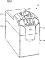
- FIG. 1 shows an appearance of a banknote depositing/dispensing machine (hereinafter merely referred to as a depositing/dispensing machine) 1.
- the depositing/dispensing machine 1 is placed in a teller counter of a bank, for example, and is shared by two tellers on the right and left sides of the depositing/dispensing machine 1.
- the depositing/dispensing machine 1 is basically bilaterally symmetrical.
- the depositing/dispensing machine 1 at least performs a depositing process for storing banknotes placed in an inlet 211 in a storage unit 3, and a dispensing process for dispensing the banknotes stored in the storage unit 3 to an outlet 231.
- the depositing/dispensing machine 1 is a so-called circulating depositing/dispensing machine.
- the banknotes dispensed in the dispensing process include the banknotes stored in the storage unit 3 in the depositing process.
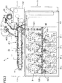
- the depositing/dispensing machine 1 is broadly divided into an upper handling unit 11 and a lower safe unit 13.
- a casing 111 constituting the handling unit 11 contains a depositing unit 21 having the inlet 211, a dispensing unit 23 having the outlet 231, a recognition unit 25 configured to recognize the banknotes, and an upper transport unit 41 which includes a looped transport path 411 connecting the depositing unit 21, the dispensing unit 23, and the recognition unit 25.
- a casing 131 constituting the safe unit 13 contains a storage unit 3 including a plurality of winding storage modules 31 (8 storage modules in the example shown in the figures), and a lower transport unit 43 including a transport path 431 connecting the looped transport path 411 of the upper transport unit 41 and the storage modules 31.
- the casing 131 constituting the safe unit 13 is a protective casing 131 configured to protect the storage unit 3 etc. contained therein at a predetermined security level or higher.
- the inlet 211 of the depositing unit 21 is a port in which the banknotes to be deposited are placed in the depositing process.
- the inlet 211 is opened upward in an upper surface of the casing 111, and can receive a plurality of banknotes at a time.
- the depositing unit 21 includes a feeding mechanism for feeding the plurality of banknotes placed in the inlet 211 one by one to the looped transport path 411.
- the outlet 231 of the dispensing unit 23 is a port to which the banknotes are dispensed in the dispensing process.
- the outlet 231 is located forward of the inlet 211 (on the right of the inlet in FIG. 2 ), and is opened obliquely upward between the upper surface and a front surface of the casing 111.
- the outlet 231 is capable of receiving a plurality of banknotes at a time.
- the recognition unit 25 is provided on the looped transport path 411 to recognize authenticity, fitness, and denomination of each of the banknotes transported on the looped transport path 411.
- the upper transport unit 41 includes the looped transport path 411 endlessly running in the casing 111.
- the banknotes are transported on the looped transport path 411 clockwise and counterclockwise in FIG. 2 .
- the looped transport path 411 includes a combination of a plurality of rollers, belts, and guides as shown in FIG. 2 .
- the looped transport path 411 allows long edge feed of the banknotes one by one with a predetermined gap kept between the banknotes.
- the looped transport path 411 and the inlet 211 are connected through a depositing path 413, and the banknotes placed in the inlet 211 are transported to the looped transport path 411 through the depositing path 413.
- a dispensing path 415 is connected to the looped transport path 411 through a diverter 417 for changing the traveling direction of the banknotes.
- An end of the dispensing path 415 is connected to the outlet 231.
- the diverter 417 is configured to keep the banknotes traveling on the looped transport path 411 clockwise or counterclockwise, or to introduce the banknotes to the dispensing path 415.
- the banknotes traveling on the looped transport path 411 clockwise or counterclockwise are selectively transported to the outlet 231 by the diverter 417 through the dispensing path 415.
- First to third diverters 419, 4111, 4113 are provided on the looped transport path 411.
- Each of the first to third diverters 419-4113 is positioned at a junction of three transport paths extending in different directions, and selectively transports the banknotes traveling from one of the transport paths to the other two transport paths. Details of the diverters are described in International Patent Publication WO2009/034758 .
- the first diverter 419 is provided at a junction between the looped transport path 411 and the transport path 431 of the lower transport unit 43.
- the first diverter 419 selectively sends the banknotes traveling on the looped transport path 411 clockwise or counterclockwise to the transport path 431 of the lower transport unit 43 to store the banknotes in the storage unit 3, or allows the banknotes fed from the storage unit 3, and traveling on the transport path 431 of the lower transport unit 43 to travel clockwise or counterclockwise on the looped transport path 411.
- the second diverter 4111 is provided at a junction between the looped transport path 411 and a connection path 4115.
- the connection path 4115 connects an escrow unit 51 which is shown in a phantom line in FIG. 2 and the looped transport path 411.
- the second diverter 4111 sends the banknotes traveling on the looped transport path 411 clockwise or counterclockwise to the connection path 4115 to store the banknotes in the escrow unit 51, or transports the banknotes fed from the escrow unit 51 clockwise or counterclockwise on the looped transport path 411.
- the third diverter 4113 is provided at a junction between the looped transport path 411 and a cassette connection path 4117. As described in detail later, the cassette connection path 4117 connects a cassette 53 which is shown in a phantom line in FIG. 2 and the looped transport path 411. The third diverter 4113 selectively sends the banknotes traveling on the looped transport path 411 clockwise or counterclockwise to the cassette connection path 4117 to store the banknotes in the cassette 53.
- the storage unit 3 includes first to eighth winding (or tape-type) storage modules 31 -1 to 31 -8 .
- a set of the eight storage modules will be indicated by a reference character "31”
- the first, second, third, ... storage modules will be indicated by reference characters "31 -1 , 31 -2 , 31 -3 , "
- the number of the storage modules 31 is not particularly limited as long as more than one storage module 31 is provided. In this example, two rows of four storage modules 31 arranged in a depth direction of the machine (right-left direction in FIG. 2 ) are vertically stacked.
- the winding storage module 31 includes a tape for guiding the banknotes, a guide, a reel for winding the tape and the banknotes, and a substantially rectangular casing containing the tape, the guide, and the reel as described in Japanese Patent Publication No. 2000-123219 .
- the winding storage module 31 includes two tapes for sandwiching the banknotes, a reel for winding the two tapes sandwiching the banknotes, and a casing containing the tapes and the reel as described in International Patent Publication No. WO2011/036782 .
- the winding storage module 31 winds the banknotes one by one to store them, and feeds the banknotes one by one in a reverse order of the storing order, i.e., the last stored banknote is first fed.
- each of the storage modules 31 includes two tape reels 313 around each of which a tape is wound, and the banknotes are sandwiched between the two tapes extending from the tape reels 313.
- the banknotes are wound around the reel 311 with predetermined gaps provided therebetween.
- Each of the storage modules 31 is provided with a sensor arranged near an opening communicating the inside and the outside of the casing to detect the passage of the banknotes.
- the transport path 431 of the lower transport unit 43 includes a combination of a plurality of rollers, belts, and guides, and the transport path 431 allows long edge feed of the banknotes one by one.
- the transport path 431 extends vertically downward from the first diverter 419 on the looped transport path 411, and a lower end thereof is branched forward (to the right in FIG. 2 ) and rearward (to the left in FIG. 2 ) in a depth direction of the machine 1.
- the branch path extending rearward of the machine 1 is arranged between the two vertically stacked rows of the storage modules 31.
- the storage modules 31 are connected to the branch path through sorters 433 -1 to 433 -8 , respectively.
- Each of the sorters 433 -1 to 433 -8 is controlled by a control unit 513 described later to sort the banknotes by the denomination and/or the fitness recognized by the recognition unit 25, and to store the sorted banknotes in the plurality of storage modules 31.
- the escrow unit 51 for temporarily retaining the banknotes, and the cassette 53 detachably provided in the protective casing 131 of the safe unit 13 can optionally be attached.
- the escrow unit 51 is placed in empty space in the casing 111 forward of the looped transport path in the depth direction as shown in a phantom line in FIG. 2 .
- the escrow unit 51 is connected to the second diverter 4111 through the connection path 4115 as described above.
- the escrow unit 51 is a winding unit including two tapes, and stores the banknotes without changing the order of the banknotes so that the last stored banknote is first fed, like the storage modules 31 described above.
- the cassette 53 is detachably placed in empty space in the protective casing 131 forward of the storage modules in the depth direction as shown in a phantom line in FIG. 2 .
- the cassette 53 is connected to the third diverter 4113 on the looped transport path 411 through the cassette connection path 4117 as described above.
- the cassette 53 contains an ascending/descending table therein to store the banknotes stacked thereon.
- the banknotes stored in the cassette 53 cannot be fed out of the cassette.
- the cassette 53 stores some of the banknotes placed in the inlet 211 in the depositing process, but not stored in the storage unit 3, i.e., overflowed banknotes.
- the banknotes which were unrecognizable and rejected in the dispensing process etc. may also be stored in the cassette 53.
- the overflowed or rejected banknotes are dispensed to the outlet 231.
- additional winding storage modules 31 may be placed in the empty space in the protective casing 131 in place of the cassette 53.
- two additional storage modules 31 may vertically be stacked in the empty space.
- Each of the two storage modules 31 is connected to the branch path extending from the lower end of the transport path 431 forward in the depth direction of the machine through the sorter described above.
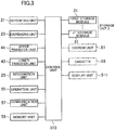
- FIG. 3 shows a structure associated with control of the depositing/dispensing machine 1.
- the depositing/dispensing machine 1 includes a control unit 513 which may basically be comprised of a well-known microcomputer.
- the control unit 513 is connected to the depositing unit 21, the dispensing unit 23, the storage unit 3 including the first to the n th storage modules 31, the upper transport unit 41, and the lower transport unit 43 so that signals can be sent and received therebetween.
- each of the units 21, 23, 3, 41, and 43 includes a sensor for detecting the banknotes traveling on the transport path, for example, and detection signals from the sensors are input to the control unit 513.
- the control unit 513 outputs control signals based on the input detection signals, and the units 21, 23, 3, 41, and 43 are operated in accordance with the signals.
- the control unit 513 is also connected to the recognition unit 25.
- the recognition unit 25 sends the recognition result to the control unit 513.
- the depositing/dispensing machine 1 is also connected to an operation unit 55 as a human interface for an operator of the depositing/dispensing machine 1, such as a teller, a communication unit 57 for sending and receiving signals between the depositing/dispensing machine 1 and a higher-ranking machine and other devices (not shown) through LAN or a serial bus, and a memory unit 59 for storing various types of information, e.g., general-purpose storage devices such as a hard disk drive, a flash memory.
- the memory unit 59 stores at least an inventory amount which is the respective numbers of the banknotes of different denominations or the amount of the banknotes stored in the depositing/dispensing machine 1.
- the memory unit 59 stores the inventory amount of each storage module 31.
- the escrow unit 51 and cassette 53 are also connected to the control unit 513, and are operated by the control signals output from the control unit 513.
- the depositing/dispensing machine 1 may optionally be provided with a display unit 511, such as a flat panel display, for displaying various types of information.
- the display unit 511 is also connected to the control unit 513.
- the control unit 513 controls the units 21, 23, 25, 3, 41, 43, 51, 53, 55, 57, 59, and 511 according to a command sent from the higher-ranking machine through the communication unit 57, and/or various commands sent through the operation unit 55.
- the depositing/dispensing machine 1 performs various processes including the depositing and dispensing processes described below.
- the processes performed by the depositing/dispensing machine 1 are stored as a log in the memory unit 59.
- the depositing process is a process for depositing (storing) the banknotes in the depositing/dispensing machine 1.
- Each of the banknotes placed in the inlet 211 is stored in any of the storage modules 31 based on the results of the recognition by the recognition unit 25, and the predetermined types (denomination, fitness, etc.) of the banknotes allocated to the storage modules 31. More specifically, the depositing/dispensing machine 1 performs the depositing process in the following manner.
- a command to start the depositing process is input to the depositing/dispensing machine 1 by operating the higher-ranking machine and/or the operation unit 55. As indicated by arrows in FIG.
- the feeding mechanism of the depositing unit 21 feeds the banknotes in the inlet 211 one by one, and the upper transport unit 41 transports the banknotes to the recognition unit 25.
- the recognition unit 25 recognizes and counts the banknotes.
- the upper transport unit 41 transports the banknotes recognized as acceptable by the recognition unit 25 (the acceptable banknotes will be referred to as normal banknotes in contrast with the rejected banknotes) from the looped transport path 411 to the transport path 431 of the lower transport unit 43 through the first diverter 419 as indicated by solid arrows in FIG. 4 .
- the lower transport unit 43 stores each of the banknotes in the predetermined storage module 31 based on the results of the recognition by the recognition unit 25, and the predetermined types of the banknotes allocated to the storage modules. Specifically, each of the banknotes is stored in the corresponding storage module 31 based on the denomination or fitness.
- the upper transport unit 41 transports the rejected banknotes which cannot be accepted by the depositing/dispensing machine 1, such as the banknotes which cannot be authenticated by the recognition unit 25, from the looped transport path 411 to the dispensing path 415 through the diverter 417 as indicated by dot-and-dash arrows in FIG. 4 .
- the rejected banknotes are then dispensed to the outlet 231.
- the banknotes rejected in the depositing process are placed again in the inlet 211, and are recognized again by the recognition unit 25.
- the inventory amount stored in the memory unit 59 is updated after the depositing process is finished.
- FIG. 4 shows the depositing process performed without providing the escrow unit 51 in the depositing/dispensing machine 1.
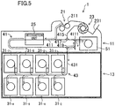
- FIG. 5 shows the depositing process performed with the escrow unit 51 provided in the depositing/dispensing machine 1.
- the feeding mechanism of the depositing unit 211 feeds the banknotes placed in the inlet 211 one by one, and the upper transport unit 41 transports the banknotes to the recognition unit 25.
- the upper transport unit 41 transports the normal banknotes recognized as acceptable by the recognition unit 25 from the looped transport path 411 to the escrow unit 51 through the second diverter 4111 as indicated by solid arrows in FIG. 5 to store the banknotes in the escrow unit.
- the rejected banknotes are dispensed to the outlet 231.
- the escrow unit 51 feeds the banknotes stored therein one by one, and the upper transport unit 41 transports the fed banknotes to the lower transport path 431 through the looped transport path 411 and the first diverter 419 as indicated by dot arrows in FIG 5 .
- the lower transport unit 43 sorts the banknotes by the denomination or fitness based on the results of the recognition by the recognition unit 25 and the predetermined types of the banknotes allocated to the storage modules to store the banknotes in the storage modules 31.
- the banknotes stored in the escrow unit 51 are dispensed to the outlet 231.
- the dispensing process is a process for dispensing the banknotes stored in the depositing/dispensing machine 1. Specifically, the dispensing process is started by performing predetermined dispensing operation of specifying the amount of money to be dispensed or the denomination and the number of the banknotes at the higher-ranking machine and/or the operation unit 55.
- the storage unit 3 feeds the specified number of the banknotes of the specified denomination from the storage module 31 as indicated by solid arrows in FIG. 6 .
- the lower transport unit 43 transports the fed banknotes to the looped transport path 411 of the upper transport unit 41 through the transport path 431.
- the upper transport unit 41 transports the banknotes to the recognition unit 25, and transports the banknotes recognized by the recognition unit 25 from the looped transport path 411 to the dispensing path 415 through the diverter 417.
- the banknotes are dispensed to the outlet 231.
- the inventory amount stored in the memory unit 59 is updated after the dispensing process is finished.
- the banknotes may be dispensed in several times, i.e., a divisional dispensing process is performed. Specifically, in the divisional dispensing process, the process is suspended when the banknotes not more than the capacity of the outlet 231 are dispensed, the dispensed banknotes are removed from the outlet 231, and then the dispensing process is restarted. The suspension and the restart of the process are repeated based on the number of the banknotes to be dispensed.
- the depositing/dispensing machine 1 does not include the escrow unit 51 and the cassette 53 as shown in FIG. 6 , the banknotes which are not recognizable by the recognition unit 25 and are rejected in the dispensing process are dispensed to the outlet 231 together with the normal banknotes.
- the depositing/dispensing machine 1 and/or the display unit 511 displays that the banknotes are rejected (error message). This can inform the operator that the rejected banknotes are contained in the banknotes dispensed to the outlet 231.
- the banknotes recognized and counted by the recognition unit 25 may irregularly be transferred to the storage modules 31 in the depositing process.
- the banknotes transferred on the transport paths 411, 431 may be skewed, may be connected without the predetermined gap therebetween, or may be overlapped.
- Such irregular transfer can be detected by checking the results of the recognition by the recognition unit 25 against the results of the detection by the sensors of the storage modules 31.
- the order of the banknotes is changed, and the banknotes may not be stored in the corresponding storage modules 31.
- the denominations or the numbers of the banknotes stored in the storage modules 31 may be uncertain.
- a process of determining the denominations and the numbers of the banknotes stored in the storage modules 31 is required. This process is called a reconciliation process.
- the reconciliation process includes, feeding all the banknotes out of the storage module 31 which requires the reconciliation, recognizing and counting the fed banknotes by the recognition unit 25, and returning the banknotes to the storage module 31.
- the banknotes fed from the storage module 31 are temporarily stored in a different storage module 31 before or after the recognition.
- the depositing/dispensing machine 1 includes the escrow unit 51
- the banknotes may temporarily be stored in the escrow unit 51.
- the irregular transfer occurred in the depositing process is detected by checking the results of the recognition by the recognition unit 25 against the results of the detection by the sensors of the storage modules 31 as described above.
- the irregular transfer is detected only after all the banknotes are stored in the storage modules 31.
- the reconciliation process needs to be performed on every storage module 31 in which at least one banknotes is stored in the depositing process, and all the banknotes stored in the corresponding storage modules 31 need to be fed out.
- the reconciliation process tends to take long time. The more banknotes the storage modules 31 store, the longer time the reconciliation takes.
- the number of the banknotes fed from the storage module 31 may become uncertain when the banknotes are connected or overlapped during the transfer, or one or more banknotes are rejected.
- the inventory amount in the storage module 31 after the dispensing process (the number of the banknotes stored in the storage module 31) becomes uncertain.
- the reconciliation process is performed on every storage module 31 from which at least one banknote is fed to determine the inventory amount in each of the storage modules 31.
- the depositing/dispensing machine 1 cannot be used during the reconciliation process performed after the depositing process and after the dispensing process. This disadvantageously delays the teller's work.
- the time taken to perform the reconciliation process is reduced by storing the banknotes in the storage module 31 in an original manner.
- every banknote stored in the storage module 31 is not fed in the reconciliation process, but at least some of the banknotes are fed to perform the reconciliation process on the storage module 31, thereby reducing the time taken for the reconciliation process.
- the reconciliation process performed by feeding some of the banknotes stored in the storage module 31 may be referred to as a partial reconciliation process.
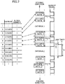
- FIG. 7 shows an example of how the banknotes are stored in the storage module 31.
- FIG. 7 shows in a center part the banknotes wound on the reel 311 of the winding storage module 31 in a developed view.
- the upward direction in FIG. 7 corresponds to a direction radially inward of the reel 311, and the downward direction in FIG. 7 corresponds to a direction radially outward of the reel 311.
- the upper banknote shown in FIG. 7 is stored earlier in the storage module 31, and the lower banknote shown in FIG. 7 is stored later in the storage module 31.
- the banknotes are sequentially fed out from the lower banknote.
- the banknotes are wound on the reel 311 with a predetermined distance d kept between each of the banknotes.
- a predetermined distance d kept between each of the banknotes.
- an interval larger than the predetermined distance d is provided between every depositing process (between every transaction).
- the memory unit 59 stores pieces of storage information corresponding to each storage module 31, each of which associating a consecutive number, denomination, and a block number of the banknote with each other as shown in a left part of FIG. 7 .
- the consecutive number is given to each of the banknotes stored in the storage module 31, and indicates the number of the banknotes stored in the storage module 31.
- the "block number" is given to a set of the banknotes stored in the storage module 31 in a period between the adjacent intervals, and can be considered as a "transaction number.”
- the consecutive number i.e., the inventory amount in the storage module 31
- the block number i.e., the interval
- the banknotes wound on the reel 311 and the pieces of storage information are associated as indicated by dot-and-dash arrows.
- the pieces of storage information stored in the memory unit 59 are updated every time the depositing process is performed.
- the depositing process in which the irregular transfer has occurred is "transaction 3" as shown in FIG. 7 .
- “Transaction 1” and “transaction 2” are depositing processes performed before the transaction 3, and the irregular transfer does not occur in the transactions 1 and 2.
- the inventory amounts in the storage module 31 after the transaction 1 and after the transaction 2 have been determined by the pieces of storage information stored in the memory unit 59.
- the reconciliation process needs to be performed on the corresponding storage module 31 after the transaction 3 is finished. At this time, only the banknotes which were wound on the reel 311 after the last interval are fed from the storage module 31. Specifically, only the banknotes stored in the storage module 31 in the transaction 3 are fed from the storage module 31 to perform the reconciliation process. Since at least the inventory amount in the storage module 31 after the transaction 2 has been determined, the inventory amount of the storage module 31 can be determined based on the inventory amount after the transaction 2 and the results of the reconciliation process.
- the reconciliation process can be performed by feeding only some of the banknotes, without feeding every banknote stored in the storage module 31. This can reduce the time for the reconciliation process.
- the banknotes wound in the transaction 3 may be fed as described above. However, for example, the banknotes stored in the depositing process in which the irregular transfer occurred (the transaction 3) and the banknotes stored in the depositing process immediately before the depositing process in which the irregular transfer occurred (the transaction 2) may be fed out of the storage module.
- the number of the fed banknotes may optionally be determined.
- the interval can be detected based on the signal from the sensor arranged near the opening of the storage module 31 as shown in a right part of FIG. 7 . Specifically, when a gap larger than the predetermined distance d is detected in feeding the banknotes, i.e., when the interval is detected, the feeding of the banknotes from the storage module 31 can be stopped.
- the interval may preferably be smaller than a gap corresponding to time T1 for a jam timer to detect jamming of the banknotes. This can prevent erroneous detection of the jamming of the banknotes.
- the banknotes can be fed from the storage module 31 until the intended interval is detected. For example, when the banknotes are fed until the last provided interval is detected, the number of the fed banknotes can be minimized, thereby advantageously reducing the time for the reconciliation process.
- the partial reconciliation process can be performed after the dispensing process, like the reconciliation process performed after the depositing process.
- the interval When the interval is provided between every transaction, the number of the intervals may be too large, and the number of the banknotes stored in the storage module 31 may be reduced.
- the interval instead of providing the interval between every transaction, the interval may be provided every time the number of the banknotes stored in the storage module 31 exceeds the predetermined number. This can reduce the number of the intervals as compared with the case where the interval is provided between every transaction, and can avoid reduction of the capacity of the storage module 31 due to the increased number of the intervals. Further, this eliminates the need to feed every banknote stored in the storage module 31 in the reconciliation process as described above, and the time for the reconciliation process can be reduced. This is particularly advantageous in striking a balance between ensuring the storage capacity and reducing the time for the reconciliation.
- the partial reconciliation process can be performed by providing the mark associated with the inventory amount in the storage module 31. Marks except for the above-described intervals between the banknotes can also be used. For example, an example where a serial number of each banknote is used as the mark, and an example where a position of the banknotes on the tape winding the banknotes in the storage module 31 (tape address) is used as the mark will be described below.
- the mark for performing the partial reconciliation process may be a physical mark including shapes and physical quantities, such as the intervals between the banknotes, the position of the banknote on the tape, and a logical mark stored as data, such as the serial number.
- the marks may be used alone, or may be used in combination to improve reliability.
- FIG. 8 shows how the banknotes are stored in the storage module 31 using the serial numbers of the banknotes.
- the banknotes are wound on the reel 311 with the predetermined distance d provided therebetween, but without the intervals between the banknotes, as shown in FIG. 8 .
- the serial numbers need to be read and stored in storing the banknotes in the storage module 31.
- the recognition unit 25 may read the serial numbers.
- the recognition unit 25 may be configured to recognize authenticity, fitness, and denomination of each of the banknotes, and to optically read the serial number printed on each of the banknotes.
- a reading unit different from the recognition unit 25 may be provided on the looped transport path 411, for example, to read the serial number.
- the serial number read in this manner is associated with the consecutive number and the denomination as a piece of information for each of the storage modules 31, and is stored in the memory unit 59 as shown in a left part of FIG. 8 .
- the inventory amount i.e., the consecutive number
- the mark i.e., the serial number
- the banknotes wound on the reel 311 and the pieces of storage information are associated as indicated by dot-and-dash arrows.
- the pieces of storage information stored in the memory unit 59 are updated every time the depositing process is performed as described above.
- the banknotes stored in the storage module 31 in the depositing process and "at least one more banknote” are fed from the storage module 31. Then, the fed banknotes are recognized and counted, and at least the serial number of the last fed banknotes is read. The read serial number is checked against the serial number contained in the pieces of storage information stored in the memory unit 59. When the read serial number is found in the storage information, the denomination and the number of the banknotes stored before the last fed banknote have been determined by the storage information in the memory unit. Thus, the feeding of the banknotes from the storage module 31 is stopped to finish the reconciliation process. When the read serial number is not found in the storage information, the feeding of the banknotes from the storage module 31 is continued until the banknote having the serial number contained in the storage information is fed.
- the reconciliation process is performed by feeding the banknotes from the storage module 31 until the banknote having the serial number contained in the storage information is fed.
- the serial number of the banknote is used as the mark, and at least some of the banknotes stored in the storage module 31 are fed for the reconciliation process.
- the time for the reconciliation process can be reduced.
- the capacity of the storage module 31 is not reduced.
- the serial number may be read and stored every time a predetermined number of the banknotes has passed, or the serial number of the banknote wound last time in each transaction may be read and stored. These reading and storing may be combined. This can advantageously save the storage capacity of the memory unit 59.
- checking the serial number whether alphabets and numerals constituting the serial number completely coincide with those of the stored serial number may be checked, or whether at least some of the alphabets and numerals coincide with those of the stored serial number may be checked. This may advantageously reduce the time for the reconciliation process. Whether at least some of the alphabets and numerals coincide with those of the stored serial numbers of more than one banknotes may be checked.
- FIG. 9 shows how the banknotes are stored using the tape address.
- the winding storage module 31 winds the banknotes by winding two tapes sandwiching the banknotes therebetween on the reel 311.
- a lengthwise position on a tape 315 and each of the banknotes wound on the reel 311 are associated with each other.
- the lengthwise position on the tape 315 will be referred to as a "tape address," and is used as the mark.
- the lengthwise position on the tape 315 i.e., the tape address
- the lengthwise position on the tape 315 can be obtained by an output (pulse number) of an encoder which is provided in the storage module 31 to detect whether the tape 315 is fed or wound back.
- calibration may be performed to associate the output of the encoder and the tape address by feeding and winding the tape 315 when the depositing/dispensing machine 1 is started (when the machine is in an initial state).
- the tape address corresponding to the wound banknote is specified by the output of the encoder every time the predetermined number of the banknotes is stored in the storage module 31 in the depositing process. Then, the tape address is associated with the consecutive number and the denomination, and is stored as the storage information in the memory unit 59.
- the inventory amount (i.e., the consecutive number) and the mark (i.e., the tape address) are associated with each other.
- the address on the tape 315 may not be stored every time the predetermined number of the banknotes is stored, but the tape address corresponding to each banknotes may be stored.
- the tape address corresponding to the banknote which is first stored in the transaction, or the tape address corresponding to the banknotes which is last stored in the transaction may be stored.
- the tape address associated with the number of the banknotes and the tape address associated with the transaction may be stored in combination.
- the banknotes wound on the reel 311 and the pieces of storage information are associated with each other as indicated by dot-and-dash arrows.
- the pieces of storage information in the memory unit 59 are updated every time the depositing process is performed as described above.
- the reconciliation process is performed by feeding the banknotes until the banknote which was stored in the storage module 31 before the current depositing process, and with which the address on the tape 315 is associated is fed. This is because the denomination and the number of the banknotes stored before the banknotes with which the address on the tape 315 is associated have been determined by the storage information stored in the memory unit 59.
- the banknotes are fed from the storage module 31 until the banknote corresponding to the stored tape address is fed.
- the tape address is used as the mark, and at least some of the banknotes stored in the storage module 31 are fed to perform the reconciliation process.
- the time for the reconciliation process can be reduced.
- the storage capacity of the storage module 31 is not reduced.
- the reconciliation process can be performed when the interval between the banknotes is associated with the tape address, instead of associating the banknote with the tape address.
- the depositing/dispensing machine 1 is configured to dispense the banknotes rejected in the dispensing process to the outlet 231 together with the normal banknotes when the cassette 53 is not attached thereto (see FIG. 6 ).
- the counting process is required to specify the banknotes and determine the number of the banknotes dispensed to the outlet 231.
- the inventory amount in the storage unit 3 may be uncertain unless the banknotes dispensed to the outlet 231 are counted. Since the depositing/dispensing machine 1 is configured to dispense the rejected banknotes to the outlet 231, the counting process must be performed when one or more banknotes are rejected in the dispensing process.
- the operator generally counts the dispensed banknotes manually or using a counting device (e.g., a banknote counter).
- a counting device e.g., a banknote counter
- the depositing/dispensing machine 1 is configured to go into standby for the counting process when one or more banknotes are rejected in the dispensing process.
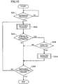
- FIG. 10 shows a flowchart of the dispensing process of the depositing/dispensing machine 1.
- step SA1 immediately after the start, whether or not a command to perform the dispensing process is input by the operator is determined.
- step SA1 is repeated. Specifically, the machine waits until the command to perform the dispensing process is input.
- the command to perform the dispensing process is input (YES is selected)
- the flow proceeds to step SA2.
- step SA2 the dispensing process is performed as described above.
- step SA3 whether or not one or more banknotes are rejected in the dispensing process is determined.
- the banknotes are not rejected (NO is selected)
- the flow is finished.
- one or more banknotes are rejected (YES is selected)
- the flow proceeds to step SA4.
- the memory unit 59 stores a log of the dispensing process in which the banknotes are rejected as a log in which the dispensing process requires a counting process, together with the inventory amount before the dispensing process.
- step SA4 whether or not a command to perform the counting process is input by the operator is determined.
- the depositing/dispensing machine 1 is configured in such a manner that the operator can optionally select whether the counting process is necessary or not after the dispensing process. For example, when the dispensing processes should sequentially be performed not to delay the teller's work, the counting process may be performed after the dispensing processes are sequentially performed. Thus, in the depositing/dispensing machine 1, the operator optionally selects whether the counting process should be performed after the dispensing process or not. This can improve usability of the depositing/dispensing machine 1.
- step SA4 when the command to perform the counting process is not input (NO is selected), the flow proceeds to step SA6.
- step SA6 whether the dispensing process is properly finished without rejecting the banknotes is determined. When the process is properly finished (YES is selected), the flow is finished. When the process is not properly finished (NO is selected), the flow returns to step SA2 to perform the dispensing process again.
- step SA4 when the command to perform the counting process is input (YES is selected), the flow proceeds to step SA5 to perform the counting process.
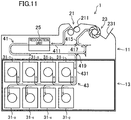
- the counting process after the dispensing process is started when the operator places every banknote dispensed to the outlet 231 (containing both the rejected banknotes and the normal banknotes) in the inlet 211, and performs predetermined operation to start the counting process.
- the feeding mechanism of the depositing unit 21 feeds the banknotes in the inlet 211 one by one, and the upper transport unit 41 transports the banknotes to the recognition unit 25.
- the recognition unit 25 recognizes and counts the banknotes.
- the upper transport unit 41 transports the banknotes that have passed the recognition unit 25 to the dispensing path 415 through the looped transport path 411 and the diverter 417 as indicated by solid arrows in FIG. 11 .
- every banknotes is dispensed again to the outlet 231.
- the result of the counting process is displayed on the higher-ranking machine and/or the display unit 511 to inform the operator of the result.
- the depositing/dispensing machine 1 performs the counting process after the dispensing process, there is no need for the operator to manually count the banknotes, thereby reducing the load on the operator. Further, since the depositing/dispensing machine 1 which performs the dispensing process can perform the counting process sequentially after the dispensing process, the operator's work is simplified, thereby further reducing the load on the operator.
- the depositing/dispensing machine 1 which can perform both of the dispensing process and the counting process can advantageously store the history and track the log.
- the results of the counting process are displayed on the higher-ranking machine or the display unit 511 as described above.
- the operator can be informed of the number of the banknotes dispensed in the dispensing process.
- the operator can manually determine the inventory amount in the storage unit 3 after the dispensing process.
- the inventory amount in the storage unit 3 of the depositing/dispensing machine 1 may automatically be determined based on the results of the counting process.
- the results of the counting process are the numbers of the banknotes of different denominations dispensed in the dispensing process which requires the counting process.
- the inventory amount after the dispensing process can be determined by subtracting the results of the counting process from the inventory amount before the dispensing process.
- the memory unit 59 stores the information. Then, the inventory amount of the depositing/dispensing machine 1 can be determined based on the results of the counting process and the information about the rejected banknotes stored in the memory unit 59.
- the counting process and the reconciliation process may be performed so that the results of the counting process and the results of the reconciliation process can be checked against the inventory amount in the storage unit 3 before the dispensing process.
- the banknotes can more suitably be handled even when the banknotes are rejected in the dispensing process.
- the reconciliation process may be a normal reconciliation process in which every banknote stored in the storage module 31 is fed, or may be the above-described partial reconciliation process.
- a command to perform the dispensing process may be input before proceeding to the counting process to properly finish the dispensing process, thereby quickly finishing the operator's work at the teller window.
- the counting process may be performed after the dispensing process is properly finished.
- the banknotes dispensed to the outlet 231 (containing both of the rejected banknotes and the normal banknotes) can separately be kept until the counting process is started.
- the results of the counting process are manually input to associate the counting results with the log of the dispensing process which requires the counting process stored in the memory unit 59, thereby determining the inventory amount after the dispensing process.
- the depositing/dispensing machine 1 does not need to perform the counting process.
- the machine 1 does not need to go into standby for the counting process.
- the memory unit 59 stores a plurality of logs of the dispensing process which requires the counting process, the operator can manually select the log of the dispensing process with which the counting results are associated in inputting the results.
- the fit banknotes which can be stored in the storage unit 3 may be stored in the storage modules 31 as indicated by dot-and-dash arrows in FIG. 11 . This allows effective use of the banknotes in the depositing/dispensing machine 1.
- the operator manually starts the counting process after the dispensing process is finished (step SA4 in FIG. 10 ).
- the counting process can automatically be started after the dispensing process.
- the counting process may be performed after all the banknotes are dispensed.
- the dispensing process may be suspended when the banknotes containing the rejected banknotes are dispensed, and then the counting process may be started. In this case, the dispensing process is restarted after the counting process is finished.
- the banknotes may merely be counted instead of recognizing and counting the banknotes. As long as the number of the banknotes fed from the depositing/dispensing machine 1 and the result of the counting process (the number of the banknotes) coincide with each other, the inventory amount can be determined based on the banknotes dispensed in the dispensing process.
- the banknotes rejected in the dispensing process may be stored in the escrow unit 51.
- the dispensing process can properly and quickly be finished by feeding only the normal banknotes to the outlet 231, and then the rejected banknotes stored in the escrow unit 51 may be counted.
- the rejected banknotes stored in the escrow unit 51 may be dispensed to the outlet 231 after the normal banknotes dispensed in the dispensing process are removed from the outlet 231, and then the rejected banknotes may be placed in the inlet 211 to perform the counting process.
- the inventory amount in the storage module 31 may manually or automatically be updated based on the count of the rejected banknotes. In particular, when the rejected banknotes are still unrecognizable, the operator may manually update the inventory amount in the storage module 31.
- the depositing/dispensing machine to which the disclosed technology is applicable is not limited to the depositing/dispensing machine placed in the teller counter.
- the disclosed technology may be applied to a depositing/dispensing machine for depositing the amount of sales of a shop etc.
- the disclosed technology is not limited to the depositing/dispensing machine for depositing/dispensing the banknotes, but may be applied to a dispensing machine for dispensing the banknotes contained therein. Further, the disclosed technology is not limited to the depositing/dispensing machine for depositing/dispensing the banknotes, but may be applied to a coin depositing/dispensing machine, a coin depositing machine, a banknote/coin depositing/dispensing machine, or a banknote/coin depositing machine.
Landscapes
- Physics & Mathematics (AREA)
- General Physics & Mathematics (AREA)
- Controlling Sheets Or Webs (AREA)
- Control Of Vending Devices And Auxiliary Devices For Vending Devices (AREA)
Claims (6)
- Appareil de manipulation d'argent (1) conçu pour réaliser au moins un processus de distribution d'argent et un processus de comptage de l'argent, l'appareil comprenant :une unité de stockage (3) comprenant une pluralité de modules de stockage (31), chacun étant conçu pour stocker l'argent et alimenter l'argent stocké ;une unité de reconnaissance (25) conçue pour reconnaître au moins si l'argent est de l'argent normal ou de l'argent devant être rej eté ;une unité de distribution unique (23) à laquelle l'argent est distribué ; etune unité de commande (513) conçue pour permettre l'alimentation d'un nombre déterminé de pièces de monnaie d'une valeur déterminée depuis l'unité de stockage (3), la reconnaissance de l'argent alimenté par l'unité de reconnaissance (25) et la distribution de l'argent reconnu à l'unité de distribution unique (23) dans le processus de distribution,l'unité de commande (513) permettant la distribution d'au moins l'argent rejeté par l'unité de reconnaissance (25) à l'unité de distribution unique (23) dans le processus de distribution et entrant ensuite en mode veille d'où un processus de comptage pour compter l'argent distribué à l'unité de distribution unique (23) est démarré par une opération prédéterminée d'un opérateur, l'argent ainsi distribué à l'unité de distribution unique (23) étant placé par l'opérateur dans une unité de dépôt (21) de l'appareil de manipulation d'argent (1) et compté par l'unité de reconnaissance (25).
- Appareil de manipulation d'argent (1) selon la revendication 1, dans lequel l'unité de commande (513) permet, dans le processus de comptage après le processus de distribution, de distribuer l'argent compté à l'unité de distribution (23).
- Appareil de manipulation d'argent (1) selon la revendication 1, dans lequel l'unité de commande (513) permet, dans le processus de comptage après le processus de distribution, de stocker l'argent compté dans l'unité de stockage (3).
- Appareil de manipulation d'argent (1) selon la revendication 3, comprenant en outre :une unité de mémoire (59) conçue pour stocker des informations liées à l'argent rejeté dans le processus de comptage.
- Appareil de manipulation d'argent (1) selon l'une quelconque des revendications 1 à 4, l'unité de commande (513) déterminant un niveau de stock dans l'unité de stockage (3) après le processus de distribution en fonction d'un résultat du processus de comptage.
- Appareil de manipulation d'argent (1) selon l'une quelconque des revendications 1 à 4, dans lequel l'unité de commande (513) réalise le processus de comptage après le processus de distribution et réalise ensuite un processus de réconciliation consistant à déterminer un niveau de stock dans l'unité de stockage (3) pour vérifier un résultat du processus de comptage et un résultat du processus de réconciliation par rapport à un niveau de stock dans l'unité de stockage (3) avant le processus de distribution.
Applications Claiming Priority (1)
| Application Number | Priority Date | Filing Date | Title |
|---|---|---|---|
| JP2011062501A JP2012198764A (ja) | 2011-03-22 | 2011-03-22 | 貨幣処理装置 |
Publications (2)
| Publication Number | Publication Date |
|---|---|
| EP2503519A1 EP2503519A1 (fr) | 2012-09-26 |
| EP2503519B1 true EP2503519B1 (fr) | 2017-11-29 |
Family
ID=45894258
Family Applications (1)
| Application Number | Title | Priority Date | Filing Date |
|---|---|---|---|
| EP12160460.7A Active EP2503519B1 (fr) | 2011-03-22 | 2012-03-21 | Appareil de traitement d'argent |
Country Status (3)
| Country | Link |
|---|---|
| US (1) | US20120241283A1 (fr) |
| EP (1) | EP2503519B1 (fr) |
| JP (1) | JP2012198764A (fr) |
Families Citing this family (11)
| Publication number | Priority date | Publication date | Assignee | Title |
|---|---|---|---|---|
| JP5786694B2 (ja) * | 2011-12-05 | 2015-09-30 | 沖電気工業株式会社 | 紙幣処理装置 |
| JP6162393B2 (ja) * | 2012-12-04 | 2017-07-12 | グローリー株式会社 | 紙幣処理装置 |
| EP2793199B1 (fr) | 2013-04-19 | 2017-03-15 | Wincor Nixdorf International GmbH | Procédé de détermination du stock d'un dispositif de stockage à rouleau basé sur des positions de moteur et dispositif correspondant |
| JP5830553B2 (ja) * | 2014-01-31 | 2015-12-09 | 日立オムロンターミナルソリューションズ株式会社 | 取引処理装置、及び取引システム |
| CN104504804B (zh) * | 2015-01-07 | 2017-05-24 | 广州广电运通信息科技有限公司 | 配钞方法、配钞装置以及金融自助设备 |
| JP2018081568A (ja) * | 2016-11-17 | 2018-05-24 | グローリー株式会社 | 紙幣収納装置および紙幣処理機 |
| JP7042847B2 (ja) * | 2018-01-19 | 2022-03-28 | グローリー株式会社 | 貨幣処理装置、貨幣処理システムおよび貨幣処理方法 |
| WO2020010563A1 (fr) * | 2018-07-12 | 2020-01-16 | 齐心商用设备(深圳)有限公司 | Détecteur de monnaie double face |
| JP2021022037A (ja) | 2019-07-25 | 2021-02-18 | グローリー株式会社 | 紙葉類処理装置 |
| JP2021051338A (ja) | 2019-09-20 | 2021-04-01 | グローリー株式会社 | 紙葉類処理装置及び紙葉類処理方法 |
| JP2021051335A (ja) | 2019-09-20 | 2021-04-01 | グローリー株式会社 | 紙葉類処理装置 |
Family Cites Families (47)
| Publication number | Priority date | Publication date | Assignee | Title |
|---|---|---|---|---|
| US6866134B2 (en) * | 1992-05-19 | 2005-03-15 | Cummins-Allison Corp. | Method and apparatus for document processing |
| US5687963A (en) * | 1994-11-14 | 1997-11-18 | Cummison-Allison Corp. | Method and apparatus for discriminating and counting documents |
| US6021883A (en) * | 1996-11-25 | 2000-02-08 | Cummins Allison, Corp. | Funds processing system |
| JP3324528B2 (ja) | 1998-10-12 | 2002-09-17 | 株式会社日立製作所 | 紙幣収納放出装置およびその装置を用いた紙幣自動入出金機 |
| JP4135238B2 (ja) * | 1998-12-08 | 2008-08-20 | 日立オムロンターミナルソリューションズ株式会社 | 紙幣入出金機 |
| US7201320B2 (en) * | 2000-02-11 | 2007-04-10 | Cummins-Allison Corp. | System and method for processing currency bills and documents bearing barcodes in a document processing device |
| US8701857B2 (en) * | 2000-02-11 | 2014-04-22 | Cummins-Allison Corp. | System and method for processing currency bills and tickets |
| DE10030227A1 (de) * | 2000-06-20 | 2002-02-21 | Giesecke & Devrient Gmbh | Verfahren und Vorrichtung zum Bearbeiten von Blattgut |
| US20050017066A1 (en) * | 2000-12-06 | 2005-01-27 | Kenneth Carter | Till control system |
| JP3902402B2 (ja) * | 2000-12-25 | 2007-04-04 | 日立オムロンターミナルソリューションズ株式会社 | 現金自動取引装置 |
| DE10117822A1 (de) * | 2001-04-10 | 2002-10-17 | Giesecke & Devrient Gmbh | Verfahren und Vorrichtung für das Sortieren von Banknoten |
| US7347358B2 (en) * | 2001-11-23 | 2008-03-25 | De La Rue International, Ltd. | Depositing items of value |
| JP3754922B2 (ja) * | 2001-12-26 | 2006-03-15 | 日立オムロンターミナルソリューションズ株式会社 | 紙幣取扱装置 |
| JP4012423B2 (ja) * | 2002-03-26 | 2007-11-21 | 日立オムロンターミナルソリューションズ株式会社 | 紙幣取扱装置 |
| JP3931112B2 (ja) * | 2002-06-05 | 2007-06-13 | 日立オムロンターミナルソリューションズ株式会社 | 紙幣取扱装置、自動取引装置、および自動取引装置のお釣り出金方法。 |
| EP1522052A4 (fr) * | 2002-06-13 | 2007-08-15 | Cummins Allison Corp | Systeme de traitement de billets de banque et procedes utilisant ledit systeme |
| JP4559697B2 (ja) * | 2002-10-24 | 2010-10-13 | グローリー株式会社 | 循環式紙幣入出金機 |
| BR0316012A (pt) * | 2002-11-08 | 2005-09-13 | Koninkl Philips Electronics Nv | Controlador hìbrido, sistema de comunicação de dados sem fio, estação sem fio, e, método de suportar avanços de qualidade de serviço |
| JP4166098B2 (ja) * | 2003-02-06 | 2008-10-15 | 日立オムロンターミナルソリューションズ株式会社 | 紙幣取扱装置 |
| JP2004318335A (ja) * | 2003-04-14 | 2004-11-11 | Hitachi Ltd | 紙幣取扱装置 |
| JP4200055B2 (ja) * | 2003-06-12 | 2008-12-24 | 日立オムロンターミナルソリューションズ株式会社 | 紙幣取引システム |
| JP4528067B2 (ja) * | 2004-09-02 | 2010-08-18 | 日立オムロンターミナルソリューションズ株式会社 | 紙幣取扱装置、紙幣管理システム、紙幣管理方法、および紙葉類取扱装置 |
| ITTO20060176A1 (it) * | 2006-03-09 | 2007-09-10 | Cts Cashpro Spa | Macchina automatica di introito ed esito contante |
| DE102006042186A1 (de) * | 2006-09-08 | 2008-03-27 | Giesecke & Devrient Gmbh | Verfahren für die Vernichtung von Banknoten |
| US20100052237A1 (en) | 2006-10-18 | 2010-03-04 | Lars Karoly Herczeg | Document handling apparatus |
| JPWO2008056404A1 (ja) * | 2006-11-06 | 2010-02-25 | グローリー株式会社 | 紙葉類識別装置および紙葉類識別方法 |
| EP2096606A4 (fr) * | 2006-12-25 | 2010-12-29 | Glory Kogyo Kk | Dispositif de traitement de billets de banque |
| DE102007005036A1 (de) * | 2007-02-01 | 2008-08-07 | Uhdenora S.P.A. | Verfahren zur Herstellung von Elektrolysezellen-Kontaktstreifen |
| KR20150093249A (ko) * | 2007-04-24 | 2015-08-17 | 글로리 글로벌 솔루션스 (홀딩스) 리미티드 | 물품을 분류하기 위한 방법 및 장치 |
| WO2008149433A1 (fr) * | 2007-06-06 | 2008-12-11 | Glory Ltd. | Conteneur de billets de banque et dispositif de traitement de billets de banque |
| WO2008152684A1 (fr) * | 2007-06-11 | 2008-12-18 | Glory Ltd. | Dispositif de manipulation de devise |
| JP5172257B2 (ja) | 2007-09-12 | 2013-03-27 | グローリー株式会社 | 紙葉類分岐機構、紙葉類処理装置および紙葉類分岐方法 |
| WO2009081085A1 (fr) * | 2007-12-21 | 2009-07-02 | De La Rue International Limited | Procédé et système de gestion de chambre forte |
| JP5156439B2 (ja) * | 2008-03-12 | 2013-03-06 | 日立オムロンターミナルソリューションズ株式会社 | 紙幣取扱装置及び現金自動取引装置 |
| CN102113027B (zh) * | 2008-07-28 | 2014-12-10 | 光荣株式会社 | 纸币处理装置 |
| US8019663B1 (en) * | 2008-07-31 | 2011-09-13 | Bank Of America Corporation | Transportation withdrawal and rebalance of cash handling device |
| JP5153530B2 (ja) | 2008-09-09 | 2013-02-27 | 日立オムロンターミナルソリューションズ株式会社 | 紙幣入出金機 |
| WO2010049968A1 (fr) * | 2008-10-28 | 2010-05-06 | グローリー株式会社 | Appareil de manipulation d'argent |
| DE102009006810A1 (de) * | 2009-01-30 | 2010-08-05 | Wincor Nixdorf International Gmbh | Vorrichtung und Verfahren zur Einzahlung und/oder Auszahlung zumindest von Banknoten mit einem ersten Nennwert und Banknoten mit einem zweiten Nennwert |
| US8267238B2 (en) * | 2009-03-16 | 2012-09-18 | Glory Ltd. | Banknote depositing machine and banknote depositing method |
| WO2010106665A1 (fr) * | 2009-03-19 | 2010-09-23 | グローリー株式会社 | Dispositif d'identification et de comptage de papier-monnaie et procédé d'identification et de comptage de papier-monnaie |
| RU2486592C1 (ru) * | 2009-03-23 | 2013-06-27 | Тэларис Лимитед | Устройство для обращения с документами |
| US8256624B2 (en) * | 2009-03-25 | 2012-09-04 | Glory Ltd. | Money handling apparatus and dispensing method thereof |
| WO2011036782A1 (fr) | 2009-09-28 | 2011-03-31 | グローリー株式会社 | Dispositif de stockage et d'avance de feuilles de papier |
| US8733531B2 (en) * | 2010-01-29 | 2014-05-27 | Glory Ltd. | Banknote handling apparatus and banknote handling method |
| JP5595955B2 (ja) * | 2011-03-18 | 2014-09-24 | 株式会社東芝 | 紙葉類処理装置 |
| US8991694B2 (en) * | 2011-12-21 | 2015-03-31 | Ncr Corporation | Item removal |
-
2011
- 2011-03-22 JP JP2011062501A patent/JP2012198764A/ja not_active Withdrawn
-
2012
- 2012-03-21 US US13/426,169 patent/US20120241283A1/en not_active Abandoned
- 2012-03-21 EP EP12160460.7A patent/EP2503519B1/fr active Active
Non-Patent Citations (1)
| Title |
|---|
| None * |
Also Published As
| Publication number | Publication date |
|---|---|
| EP2503519A1 (fr) | 2012-09-26 |
| JP2012198764A (ja) | 2012-10-18 |
| US20120241283A1 (en) | 2012-09-27 |
Similar Documents
| Publication | Publication Date | Title |
|---|---|---|
| EP2503519B1 (fr) | Appareil de traitement d'argent | |
| US8579278B2 (en) | Paper sheet handling apparatus with first and second transport surfaces | |
| US8958904B2 (en) | Banknote handling apparatus | |
| CN103988236B (zh) | 纸币处理装置 | |
| US9123191B2 (en) | Money depositing/dispensing device and money management method of money depositing/dispensing device | |
| US9342942B2 (en) | Bill-recycling ATM for teller with supplementary collection box and banknote transfer method applied thereto | |
| CN104517349B (zh) | 纸币处理装置 | |
| JP2010272024A (ja) | 自動取引装置 | |
| JP3931112B2 (ja) | 紙幣取扱装置、自動取引装置、および自動取引装置のお釣り出金方法。 | |
| JP2019036004A (ja) | 貨幣処理装置 | |
| JP2008027023A (ja) | 現金処理装置 | |
| JP2014232446A (ja) | 現金処理装置 | |
| JP2010015196A (ja) | 硬貨入出金機 | |
| JP2014029618A (ja) | 紙幣処理装置及び紙幣処理方法 | |
| JP2009230680A (ja) | 釣銭機及び貨幣取扱方法 | |
| JP6681234B2 (ja) | 貨幣処理装置 | |
| JP5638358B2 (ja) | 紙幣処理装置 | |
| JP6446336B2 (ja) | 硬貨処理装置 | |
| JP2011170417A (ja) | 貨幣類取扱装置および現金自動取引装置 | |
| JP4857719B2 (ja) | 紙幣入出金機 | |
| JP2018032290A (ja) | 貨幣処理装置、貨幣処理システム、及び、貨幣処理方法 | |
| JP5965236B2 (ja) | 紙幣処理装置及び紙幣処理方法 | |
| JP6399918B2 (ja) | 貨幣処理機および貨幣処理方法 | |
| JPH0644438A (ja) | 紙幣入出金機 | |
| JPS61194593A (ja) | 還流式現金自動取引装置 |
Legal Events
| Date | Code | Title | Description |
|---|---|---|---|
| PUAI | Public reference made under article 153(3) epc to a published international application that has entered the european phase |
Free format text: ORIGINAL CODE: 0009012 |
|
| AK | Designated contracting states |
Kind code of ref document: A1 Designated state(s): AL AT BE BG CH CY CZ DE DK EE ES FI FR GB GR HR HU IE IS IT LI LT LU LV MC MK MT NL NO PL PT RO RS SE SI SK SM TR |
|
| AX | Request for extension of the european patent |
Extension state: BA ME |
|
| 17P | Request for examination filed |
Effective date: 20130326 |
|
| 17Q | First examination report despatched |
Effective date: 20160812 |
|
| GRAP | Despatch of communication of intention to grant a patent |
Free format text: ORIGINAL CODE: EPIDOSNIGR1 |
|
| INTG | Intention to grant announced |
Effective date: 20170620 |
|
| GRAS | Grant fee paid |
Free format text: ORIGINAL CODE: EPIDOSNIGR3 |
|
| GRAA | (expected) grant |
Free format text: ORIGINAL CODE: 0009210 |
|
| AK | Designated contracting states |
Kind code of ref document: B1 Designated state(s): AL AT BE BG CH CY CZ DE DK EE ES FI FR GB GR HR HU IE IS IT LI LT LU LV MC MK MT NL NO PL PT RO RS SE SI SK SM TR |
|
| REG | Reference to a national code |
Ref country code: CH Ref legal event code: EP |
|
| REG | Reference to a national code |
Ref country code: AT Ref legal event code: REF Ref document number: 951053 Country of ref document: AT Kind code of ref document: T Effective date: 20171215 |
|
| REG | Reference to a national code |
Ref country code: IE Ref legal event code: FG4D |
|
| REG | Reference to a national code |
Ref country code: DE Ref legal event code: R096 Ref document number: 602012040253 Country of ref document: DE |
|
| REG | Reference to a national code |
Ref country code: FR Ref legal event code: PLFP Year of fee payment: 7 |
|
| REG | Reference to a national code |
Ref country code: NL Ref legal event code: MP Effective date: 20171129 |
|
| REG | Reference to a national code |
Ref country code: LT Ref legal event code: MG4D |
|
| REG | Reference to a national code |
Ref country code: AT Ref legal event code: MK05 Ref document number: 951053 Country of ref document: AT Kind code of ref document: T Effective date: 20171129 |
|
| PG25 | Lapsed in a contracting state [announced via postgrant information from national office to epo] |
Ref country code: SE Free format text: LAPSE BECAUSE OF FAILURE TO SUBMIT A TRANSLATION OF THE DESCRIPTION OR TO PAY THE FEE WITHIN THE PRESCRIBED TIME-LIMIT Effective date: 20171129 Ref country code: LT Free format text: LAPSE BECAUSE OF FAILURE TO SUBMIT A TRANSLATION OF THE DESCRIPTION OR TO PAY THE FEE WITHIN THE PRESCRIBED TIME-LIMIT Effective date: 20171129 Ref country code: NO Free format text: LAPSE BECAUSE OF FAILURE TO SUBMIT A TRANSLATION OF THE DESCRIPTION OR TO PAY THE FEE WITHIN THE PRESCRIBED TIME-LIMIT Effective date: 20180228 Ref country code: ES Free format text: LAPSE BECAUSE OF FAILURE TO SUBMIT A TRANSLATION OF THE DESCRIPTION OR TO PAY THE FEE WITHIN THE PRESCRIBED TIME-LIMIT Effective date: 20171129 Ref country code: FI Free format text: LAPSE BECAUSE OF FAILURE TO SUBMIT A TRANSLATION OF THE DESCRIPTION OR TO PAY THE FEE WITHIN THE PRESCRIBED TIME-LIMIT Effective date: 20171129 |
|
| PG25 | Lapsed in a contracting state [announced via postgrant information from national office to epo] |
Ref country code: RS Free format text: LAPSE BECAUSE OF FAILURE TO SUBMIT A TRANSLATION OF THE DESCRIPTION OR TO PAY THE FEE WITHIN THE PRESCRIBED TIME-LIMIT Effective date: 20171129 Ref country code: HR Free format text: LAPSE BECAUSE OF FAILURE TO SUBMIT A TRANSLATION OF THE DESCRIPTION OR TO PAY THE FEE WITHIN THE PRESCRIBED TIME-LIMIT Effective date: 20171129 Ref country code: LV Free format text: LAPSE BECAUSE OF FAILURE TO SUBMIT A TRANSLATION OF THE DESCRIPTION OR TO PAY THE FEE WITHIN THE PRESCRIBED TIME-LIMIT Effective date: 20171129 Ref country code: AT Free format text: LAPSE BECAUSE OF FAILURE TO SUBMIT A TRANSLATION OF THE DESCRIPTION OR TO PAY THE FEE WITHIN THE PRESCRIBED TIME-LIMIT Effective date: 20171129 Ref country code: BG Free format text: LAPSE BECAUSE OF FAILURE TO SUBMIT A TRANSLATION OF THE DESCRIPTION OR TO PAY THE FEE WITHIN THE PRESCRIBED TIME-LIMIT Effective date: 20180228 Ref country code: GR Free format text: LAPSE BECAUSE OF FAILURE TO SUBMIT A TRANSLATION OF THE DESCRIPTION OR TO PAY THE FEE WITHIN THE PRESCRIBED TIME-LIMIT Effective date: 20180301 |
|
| PG25 | Lapsed in a contracting state [announced via postgrant information from national office to epo] |
Ref country code: NL Free format text: LAPSE BECAUSE OF FAILURE TO SUBMIT A TRANSLATION OF THE DESCRIPTION OR TO PAY THE FEE WITHIN THE PRESCRIBED TIME-LIMIT Effective date: 20171129 |
|
| PG25 | Lapsed in a contracting state [announced via postgrant information from national office to epo] |
Ref country code: EE Free format text: LAPSE BECAUSE OF FAILURE TO SUBMIT A TRANSLATION OF THE DESCRIPTION OR TO PAY THE FEE WITHIN THE PRESCRIBED TIME-LIMIT Effective date: 20171129 Ref country code: DK Free format text: LAPSE BECAUSE OF FAILURE TO SUBMIT A TRANSLATION OF THE DESCRIPTION OR TO PAY THE FEE WITHIN THE PRESCRIBED TIME-LIMIT Effective date: 20171129 Ref country code: SK Free format text: LAPSE BECAUSE OF FAILURE TO SUBMIT A TRANSLATION OF THE DESCRIPTION OR TO PAY THE FEE WITHIN THE PRESCRIBED TIME-LIMIT Effective date: 20171129 Ref country code: CZ Free format text: LAPSE BECAUSE OF FAILURE TO SUBMIT A TRANSLATION OF THE DESCRIPTION OR TO PAY THE FEE WITHIN THE PRESCRIBED TIME-LIMIT Effective date: 20171129 Ref country code: CY Free format text: LAPSE BECAUSE OF FAILURE TO SUBMIT A TRANSLATION OF THE DESCRIPTION OR TO PAY THE FEE WITHIN THE PRESCRIBED TIME-LIMIT Effective date: 20171129 |
|
| REG | Reference to a national code |
Ref country code: DE Ref legal event code: R097 Ref document number: 602012040253 Country of ref document: DE |
|
| PG25 | Lapsed in a contracting state [announced via postgrant information from national office to epo] |
Ref country code: PL Free format text: LAPSE BECAUSE OF FAILURE TO SUBMIT A TRANSLATION OF THE DESCRIPTION OR TO PAY THE FEE WITHIN THE PRESCRIBED TIME-LIMIT Effective date: 20171129 Ref country code: SM Free format text: LAPSE BECAUSE OF FAILURE TO SUBMIT A TRANSLATION OF THE DESCRIPTION OR TO PAY THE FEE WITHIN THE PRESCRIBED TIME-LIMIT Effective date: 20171129 Ref country code: RO Free format text: LAPSE BECAUSE OF FAILURE TO SUBMIT A TRANSLATION OF THE DESCRIPTION OR TO PAY THE FEE WITHIN THE PRESCRIBED TIME-LIMIT Effective date: 20171129 |
|
| PLBE | No opposition filed within time limit |
Free format text: ORIGINAL CODE: 0009261 |
|
| STAA | Information on the status of an ep patent application or granted ep patent |
Free format text: STATUS: NO OPPOSITION FILED WITHIN TIME LIMIT |
|
| REG | Reference to a national code |
Ref country code: CH Ref legal event code: PL |
|
| 26N | No opposition filed |
Effective date: 20180830 |
|
| PG25 | Lapsed in a contracting state [announced via postgrant information from national office to epo] |
Ref country code: SI Free format text: LAPSE BECAUSE OF FAILURE TO SUBMIT A TRANSLATION OF THE DESCRIPTION OR TO PAY THE FEE WITHIN THE PRESCRIBED TIME-LIMIT Effective date: 20171129 Ref country code: MC Free format text: LAPSE BECAUSE OF FAILURE TO SUBMIT A TRANSLATION OF THE DESCRIPTION OR TO PAY THE FEE WITHIN THE PRESCRIBED TIME-LIMIT Effective date: 20171129 |
|
| REG | Reference to a national code |
Ref country code: BE Ref legal event code: MM Effective date: 20180331 |
|
| REG | Reference to a national code |
Ref country code: IE Ref legal event code: MM4A |
|
| PG25 | Lapsed in a contracting state [announced via postgrant information from national office to epo] |
Ref country code: LU Free format text: LAPSE BECAUSE OF NON-PAYMENT OF DUE FEES Effective date: 20180321 |
|
| PG25 | Lapsed in a contracting state [announced via postgrant information from national office to epo] |
Ref country code: IE Free format text: LAPSE BECAUSE OF NON-PAYMENT OF DUE FEES Effective date: 20180321 |
|
| PG25 | Lapsed in a contracting state [announced via postgrant information from national office to epo] |
Ref country code: LI Free format text: LAPSE BECAUSE OF NON-PAYMENT OF DUE FEES Effective date: 20180331 Ref country code: BE Free format text: LAPSE BECAUSE OF NON-PAYMENT OF DUE FEES Effective date: 20180331 Ref country code: CH Free format text: LAPSE BECAUSE OF NON-PAYMENT OF DUE FEES Effective date: 20180331 |
|
| PG25 | Lapsed in a contracting state [announced via postgrant information from national office to epo] |
Ref country code: MT Free format text: LAPSE BECAUSE OF NON-PAYMENT OF DUE FEES Effective date: 20180321 |
|
| PG25 | Lapsed in a contracting state [announced via postgrant information from national office to epo] |
Ref country code: TR Free format text: LAPSE BECAUSE OF FAILURE TO SUBMIT A TRANSLATION OF THE DESCRIPTION OR TO PAY THE FEE WITHIN THE PRESCRIBED TIME-LIMIT Effective date: 20171129 |
|
| PG25 | Lapsed in a contracting state [announced via postgrant information from national office to epo] |
Ref country code: HU Free format text: LAPSE BECAUSE OF FAILURE TO SUBMIT A TRANSLATION OF THE DESCRIPTION OR TO PAY THE FEE WITHIN THE PRESCRIBED TIME-LIMIT; INVALID AB INITIO Effective date: 20120321 Ref country code: PT Free format text: LAPSE BECAUSE OF FAILURE TO SUBMIT A TRANSLATION OF THE DESCRIPTION OR TO PAY THE FEE WITHIN THE PRESCRIBED TIME-LIMIT Effective date: 20171129 |
|
| PG25 | Lapsed in a contracting state [announced via postgrant information from national office to epo] |
Ref country code: MK Free format text: LAPSE BECAUSE OF NON-PAYMENT OF DUE FEES Effective date: 20171129 |
|
| PG25 | Lapsed in a contracting state [announced via postgrant information from national office to epo] |
Ref country code: AL Free format text: LAPSE BECAUSE OF FAILURE TO SUBMIT A TRANSLATION OF THE DESCRIPTION OR TO PAY THE FEE WITHIN THE PRESCRIBED TIME-LIMIT Effective date: 20171129 Ref country code: IS Free format text: LAPSE BECAUSE OF FAILURE TO SUBMIT A TRANSLATION OF THE DESCRIPTION OR TO PAY THE FEE WITHIN THE PRESCRIBED TIME-LIMIT Effective date: 20180329 |
|
| P01 | Opt-out of the competence of the unified patent court (upc) registered |
Effective date: 20230531 |
|
| PGFP | Annual fee paid to national office [announced via postgrant information from national office to epo] |
Ref country code: GB Payment date: 20260324 Year of fee payment: 15 |
|
| PGFP | Annual fee paid to national office [announced via postgrant information from national office to epo] |
Ref country code: DE Payment date: 20260319 Year of fee payment: 15 |
|
| PGFP | Annual fee paid to national office [announced via postgrant information from national office to epo] |
Ref country code: IT Payment date: 20260324 Year of fee payment: 15 |
|
| PGFP | Annual fee paid to national office [announced via postgrant information from national office to epo] |
Ref country code: FR Payment date: 20260320 Year of fee payment: 15 |