EP2498916B2 - Vorrichtung und verfahren zur konservierung von bauteilen - Google Patents
Vorrichtung und verfahren zur konservierung von bauteilen Download PDFInfo
- Publication number
- EP2498916B2 EP2498916B2 EP10779712.8A EP10779712A EP2498916B2 EP 2498916 B2 EP2498916 B2 EP 2498916B2 EP 10779712 A EP10779712 A EP 10779712A EP 2498916 B2 EP2498916 B2 EP 2498916B2
- Authority
- EP
- European Patent Office
- Prior art keywords
- hardener
- preservative agent
- application
- preservative
- application element
- Prior art date
- Legal status (The legal status is an assumption and is not a legal conclusion. Google has not performed a legal analysis and makes no representation as to the accuracy of the status listed.)
- Not-in-force
Links
Images



Classifications
-
- B—PERFORMING OPERATIONS; TRANSPORTING
- B05—SPRAYING OR ATOMISING IN GENERAL; APPLYING FLUENT MATERIALS TO SURFACES, IN GENERAL
- B05B—SPRAYING APPARATUS; ATOMISING APPARATUS; NOZZLES
- B05B7/00—Spraying apparatus for discharge of liquids or other fluent materials from two or more sources, e.g. of liquid and air, of powder and gas
- B05B7/02—Spray pistols; Apparatus for discharge
- B05B7/04—Spray pistols; Apparatus for discharge with arrangements for mixing liquids or other fluent materials before discharge
- B05B7/0408—Spray pistols; Apparatus for discharge with arrangements for mixing liquids or other fluent materials before discharge with arrangements for mixing two or more liquids
-
- B—PERFORMING OPERATIONS; TRANSPORTING
- B01—PHYSICAL OR CHEMICAL PROCESSES OR APPARATUS IN GENERAL
- B01F—MIXING, e.g. DISSOLVING, EMULSIFYING OR DISPERSING
- B01F25/00—Flow mixers; Mixers for falling materials, e.g. solid particles
- B01F25/20—Jet mixers, i.e. mixers using high-speed fluid streams
- B01F25/23—Mixing by intersecting jets
-
- B—PERFORMING OPERATIONS; TRANSPORTING
- B05—SPRAYING OR ATOMISING IN GENERAL; APPLYING FLUENT MATERIALS TO SURFACES, IN GENERAL
- B05B—SPRAYING APPARATUS; ATOMISING APPARATUS; NOZZLES
- B05B13/00—Machines or plants for applying liquids or other fluent materials to surfaces of objects or other work by spraying, not covered by groups B05B1/00 - B05B11/00
- B05B13/06—Machines or plants for applying liquids or other fluent materials to surfaces of objects or other work by spraying, not covered by groups B05B1/00 - B05B11/00 specially designed for treating the inside of hollow bodies
- B05B13/0627—Arrangements of nozzles or spray heads specially adapted for treating the inside of hollow bodies
-
- B—PERFORMING OPERATIONS; TRANSPORTING
- B05—SPRAYING OR ATOMISING IN GENERAL; APPLYING FLUENT MATERIALS TO SURFACES, IN GENERAL
- B05B—SPRAYING APPARATUS; ATOMISING APPARATUS; NOZZLES
- B05B7/00—Spraying apparatus for discharge of liquids or other fluent materials from two or more sources, e.g. of liquid and air, of powder and gas
- B05B7/02—Spray pistols; Apparatus for discharge
- B05B7/06—Spray pistols; Apparatus for discharge with at least one outlet orifice surrounding another approximately in the same plane
- B05B7/061—Spray pistols; Apparatus for discharge with at least one outlet orifice surrounding another approximately in the same plane with several liquid outlets discharging one or several liquids
-
- B—PERFORMING OPERATIONS; TRANSPORTING
- B05—SPRAYING OR ATOMISING IN GENERAL; APPLYING FLUENT MATERIALS TO SURFACES, IN GENERAL
- B05B—SPRAYING APPARATUS; ATOMISING APPARATUS; NOZZLES
- B05B7/00—Spraying apparatus for discharge of liquids or other fluent materials from two or more sources, e.g. of liquid and air, of powder and gas
- B05B7/02—Spray pistols; Apparatus for discharge
- B05B7/08—Spray pistols; Apparatus for discharge with separate outlet orifices, e.g. to form parallel jets, i.e. the axis of the jets being parallel, to form intersecting jets, i.e. the axis of the jets converging but not necessarily intersecting at a point
- B05B7/0807—Spray pistols; Apparatus for discharge with separate outlet orifices, e.g. to form parallel jets, i.e. the axis of the jets being parallel, to form intersecting jets, i.e. the axis of the jets converging but not necessarily intersecting at a point to form intersecting jets
- B05B7/0846—Spray pistols; Apparatus for discharge with separate outlet orifices, e.g. to form parallel jets, i.e. the axis of the jets being parallel, to form intersecting jets, i.e. the axis of the jets converging but not necessarily intersecting at a point to form intersecting jets with jets being only jets constituted by a liquid or a mixture containing a liquid
-
- B—PERFORMING OPERATIONS; TRANSPORTING
- B01—PHYSICAL OR CHEMICAL PROCESSES OR APPARATUS IN GENERAL
- B01F—MIXING, e.g. DISSOLVING, EMULSIFYING OR DISPERSING
- B01F2101/00—Mixing characterised by the nature of the mixed materials or by the application field
- B01F2101/2305—Mixers of the two-component package type, i.e. where at least two components are separately stored, and are mixed in the moment of application
-
- B—PERFORMING OPERATIONS; TRANSPORTING
- B05—SPRAYING OR ATOMISING IN GENERAL; APPLYING FLUENT MATERIALS TO SURFACES, IN GENERAL
- B05B—SPRAYING APPARATUS; ATOMISING APPARATUS; NOZZLES
- B05B13/00—Machines or plants for applying liquids or other fluent materials to surfaces of objects or other work by spraying, not covered by groups B05B1/00 - B05B11/00
- B05B13/02—Means for supporting work; Arrangement or mounting of spray heads; Adaptation or arrangement of means for feeding work
- B05B13/04—Means for supporting work; Arrangement or mounting of spray heads; Adaptation or arrangement of means for feeding work the spray heads being moved during spraying operation
- B05B13/0431—Means for supporting work; Arrangement or mounting of spray heads; Adaptation or arrangement of means for feeding work the spray heads being moved during spraying operation with spray heads moved by robots or articulated arms, e.g. for applying liquid or other fluent material to three-dimensional [3D] surfaces
-
- B—PERFORMING OPERATIONS; TRANSPORTING
- B05—SPRAYING OR ATOMISING IN GENERAL; APPLYING FLUENT MATERIALS TO SURFACES, IN GENERAL
- B05B—SPRAYING APPARATUS; ATOMISING APPARATUS; NOZZLES
- B05B13/00—Machines or plants for applying liquids or other fluent materials to surfaces of objects or other work by spraying, not covered by groups B05B1/00 - B05B11/00
- B05B13/02—Means for supporting work; Arrangement or mounting of spray heads; Adaptation or arrangement of means for feeding work
- B05B13/04—Means for supporting work; Arrangement or mounting of spray heads; Adaptation or arrangement of means for feeding work the spray heads being moved during spraying operation
- B05B13/0431—Means for supporting work; Arrangement or mounting of spray heads; Adaptation or arrangement of means for feeding work the spray heads being moved during spraying operation with spray heads moved by robots or articulated arms, e.g. for applying liquid or other fluent material to three-dimensional [3D] surfaces
- B05B13/0433—Means for supporting work; Arrangement or mounting of spray heads; Adaptation or arrangement of means for feeding work the spray heads being moved during spraying operation with spray heads moved by robots or articulated arms, e.g. for applying liquid or other fluent material to three-dimensional [3D] surfaces the work being vehicle components, e.g. vehicle bodies
-
- B—PERFORMING OPERATIONS; TRANSPORTING
- B05—SPRAYING OR ATOMISING IN GENERAL; APPLYING FLUENT MATERIALS TO SURFACES, IN GENERAL
- B05B—SPRAYING APPARATUS; ATOMISING APPARATUS; NOZZLES
- B05B13/00—Machines or plants for applying liquids or other fluent materials to surfaces of objects or other work by spraying, not covered by groups B05B1/00 - B05B11/00
- B05B13/02—Means for supporting work; Arrangement or mounting of spray heads; Adaptation or arrangement of means for feeding work
- B05B13/04—Means for supporting work; Arrangement or mounting of spray heads; Adaptation or arrangement of means for feeding work the spray heads being moved during spraying operation
- B05B13/0447—Installation or apparatus for applying liquid or other fluent material to conveyed separate articles
- B05B13/0452—Installation or apparatus for applying liquid or other fluent material to conveyed separate articles the objects being vehicle components, e.g. vehicle bodies
-
- B—PERFORMING OPERATIONS; TRANSPORTING
- B05—SPRAYING OR ATOMISING IN GENERAL; APPLYING FLUENT MATERIALS TO SURFACES, IN GENERAL
- B05B—SPRAYING APPARATUS; ATOMISING APPARATUS; NOZZLES
- B05B13/00—Machines or plants for applying liquids or other fluent materials to surfaces of objects or other work by spraying, not covered by groups B05B1/00 - B05B11/00
- B05B13/02—Means for supporting work; Arrangement or mounting of spray heads; Adaptation or arrangement of means for feeding work
- B05B13/04—Means for supporting work; Arrangement or mounting of spray heads; Adaptation or arrangement of means for feeding work the spray heads being moved during spraying operation
- B05B13/0447—Installation or apparatus for applying liquid or other fluent material to conveyed separate articles
- B05B13/0457—Installation or apparatus for applying liquid or other fluent material to conveyed separate articles specially designed for applying liquid or other fluent material to three-dimensional [3D] surfaces of the work, e.g. by using several moving spray heads
-
- B—PERFORMING OPERATIONS; TRANSPORTING
- B05—SPRAYING OR ATOMISING IN GENERAL; APPLYING FLUENT MATERIALS TO SURFACES, IN GENERAL
- B05C—APPARATUS FOR APPLYING FLUENT MATERIALS TO SURFACES, IN GENERAL
- B05C5/00—Apparatus in which liquid or other fluent material is projected, poured or allowed to flow on to the surface of the work
-
- B—PERFORMING OPERATIONS; TRANSPORTING
- B05—SPRAYING OR ATOMISING IN GENERAL; APPLYING FLUENT MATERIALS TO SURFACES, IN GENERAL
- B05C—APPARATUS FOR APPLYING FLUENT MATERIALS TO SURFACES, IN GENERAL
- B05C5/00—Apparatus in which liquid or other fluent material is projected, poured or allowed to flow on to the surface of the work
- B05C5/02—Apparatus in which liquid or other fluent material is projected, poured or allowed to flow on to the surface of the work the liquid or other fluent material being discharged through an outlet orifice by pressure, e.g. from an outlet device in contact or almost in contact, with the work
- B05C5/027—Coating heads with several outlets, e.g. aligned transversally to the moving direction of a web to be coated
Definitions
- the invention relates to a device and a method for the cavity preservation of motor vehicle body components with a preservative according to claims 1 and 6.
- the invention is preferably used for the preservation of hard-to-access surfaces that are to be preserved, which besides cavity preservation e.g. also applies to seam seals (e.g. flared seams), etc. of motor vehicle body components.
- Cavity conservation i.e. The preservation of an interior surface of a cavity is mostly used in high-quality vehicles in order to significantly extend the corrosion protection.
- the use of cavity preservation is typical, particularly in countries in which high commitments are made regarding the so-called "rust protection guarantee” (corrosion protection guarantee), which is particularly true for many European countries.
- rust protection guarantee corrosion protection guarantee
- the cavities to be preserved in the motor vehicle body are poured out with solvent-free wax which has been liquefied by heating, a part of the wax being deposited on the cavity walls and thereby preserving them while the excess wax runs off.
- the wax serving as a preservative is sprayed onto the inner walls of the cavities, for which purpose, for example, an application tube (lance) can be used, which is inserted into the cavities from the outside and has outlet openings for the wax.
- an application tube for example, an application tube (lance) can be used, which is inserted into the cavities from the outside and has outlet openings for the wax.
- a wax is usually used as the material for cavity preservation.
- processing is typical in which the wax is atomized together with air in a pre-atomization chamber and is passed to the body by means of air through hoses (e.g. 3-8 m length).
- the air is used for atomization, transport and distribution in the cavity.
- the wax is introduced into the cavity and is usually intended to seal it. To do this, it must run. This is usually supported by a tilting station that "tilts" the body part in order to support the course (penetration) of the wax. Openings (outlet bores) in the body part to be preserved indicate that the cavity has been coated successfully.
- This disadvantage is minimized by providing a wax dryer.
- This wax dryer heats the body parts to a certain minimum temperature over a certain minimum time, e.g. 1 min. at 60 ° C.
- a common wax dryer length is e.g. 60 m.
- the leakage of wax is essentially stopped.
- the wax hardens for a few more days / weeks, but never becomes completely solid, but remains flexible.
- Such wax dryers have a number of disadvantages, e.g. high energy consumption in operation, high investment and / or maintenance costs, high cleaning effort, large space consumption, lack of retrofitting for many customers, etc.
- DE 10 2008 011 489 A1 discloses a method for cavity sealing of a motor vehicle component by spraying a curable preservative such as. B. wax, to which a crosslinking component can be added directly before spraying.
- a spray gun known per se, is provided for applying the preservative and engages with an application element in the cavity to be preserved.
- the crosslinking component is mixed with the preservative in a mixing chamber.
- DE 103 20 341 A1 discloses a method of forming a polyurethane article wherein first and second bases of a polyurethane system are injected into an unlimited space above a mold.
- US 5,071,683 A discloses a similar process for making an elastomeric polyurethane layer in a mold.
- GB 2 251 396 A discloses schematically a method of applying two components from two nozzles.
- the object of the invention is to provide an improved device and an improved method for preserving components.
- the invention encompasses the general technical teaching of mixing a preservative and a hardener in the preservation of components in order to allow the preservative to harden more quickly, in particular in order to achieve a "drop stop".
- the device according to the invention for preserving components with a preservative is distinguished in particular by the fact that, in addition to the preservative, a hardener is applied which reacts with the preservative in order to allow the preservative to harden.
- the device is therefore preferably provided in order to apply a hardener in addition to the preservative in order to react with the preservative, as a result of which hardening of the preservative can be achieved.
- the device can be designed such that no or only very few sections of the device come into contact with a mixture of preservative and hardener.
- the preservative hardens through the hardener from the mixing process.
- a conventional mixer cannot sit directly in the nozzle for reasons of space, but would have to be installed a few centimeters to meters from the nozzle. Since the hardener reacts with water, the water or residual moisture from the air / compressed air is sufficient to initiate a reaction.
- the process of blowing the feed line empty after pre-atomization and / or mixing would leave residues in the feed line that would no longer be completely discharged even in subsequent coating processes. Even rinsing would not make the feed line and other contaminated device parts 100% clean.
- the preservative and hardener can preferably be mixed in terms of flow technology at an end section of the device, for example in an application device, an application element and / or a nozzle. It is also possible to design the device in such a way that the preservative and the hardener mix in flight (in the air), in a cavity to be preserved and / or on a component to be preserved. Mixing is thus preferably initiated in an application device, an application element, a nozzle, in flight (in the air), in a cavity to be preserved and / or on a component to be preserved.
- the device comprises an application device for applying the preservative and the hardener to the component to be preserved, a preservative line for supplying the preservative to the application device and a hardener line for supplying the hardener to the application device
- the application device has an application element with an outlet opening.
- the application element can be, for example, an application tube, a lance, a probe, etc.
- the application element has a nozzle at which the outlet opening is provided.
- the preservative line and the hardener line open into the application element in such a way that the preservative and the hardener mix in the application element. The mixing process can thus be initiated in the application element.
- the advantage of this is that only a few sections come into contact with a mixture of preservative and hardener.
- the preservative line and the hardener line open into the application element in such a way that the preservative and the hardener mix directly in front of the first nozzle and / or in the nozzle.
- the mixing process can thus be initiated immediately before and / or in the nozzle.
- the advantage of this is that only a few sections come into contact with a mixture of preservative and hardener.
- the application element is designed, for example, in such a way that it can be guided through an opening into a cavity to be preserved in order to spray its inner surfaces to be preserved with preservative and hardener.
- a mixer in particular in the application device, an application element, preferably an application tube, and / or in a nozzle.
- the mixer can also extend over at least two of the aforementioned sections (e.g. from the application tube into the nozzle).
- the mixer e.g. To accommodate in the nozzle and / or in the application tube, the mixer must be of correspondingly small dimensions and still achieve sufficient mixer results, which conventional mixers are unable to do.
- a mixer suitable for the invention could preferably be produced by means of generative processes (e.g. rapid prototyping).
- means can be provided, in particular for the application device, the application element and / or the nozzle with a solvent / rinsing agent, a reactive substance (for example a reaction retardant, for example an organic acid chloride), which essentially stops or inhibits curing, and / or a monofunctional substance (e.g. propanol or butanol, especially in the case of an isocyanate functionality) that reacts with the preservative and / or the hardener to essentially stop or inhibit hardening (in particular by essentially preventing its chain reaction) to flow through, to coat and / or to fill.
- a reactive substance for example a reaction retardant, for example an organic acid chloride
- a monofunctional substance e.g. propanol or butanol, especially in the case of an isocyanate functionality
- the reactive substance and / or the monofunctional substance thus act as a blocking agent in order to delay, preferably substantially prevent, hardening of the preservative or the mixture comprising preservative and hardener. It is possible that the mixture contains other components such as e.g. comprises a solvent and / or rinsing agent.
- the monofunctional substance is preferably a reactive, monofunctional substance that reacts with a preservative component and / or a hardener component, preferably with a hardener component, but does not lead to polymer chains due to its monofunctionality, but ideally leads to a molecule or Oligomer from a hardener molecule and two blocking agent molecules.
- amines or alcohols preferably lower alcohols, such as e.g. Ethanol, propanol, butanol and / or their isomers into consideration.
- the reactivity of the chain reaction, which is essentially prevented by the monofunctional substance, should be higher than that of the chain-forming reaction. Because e.g. If the bi- or multifunctional hardener molecules react with a short-chain monofunctional molecule, the viscosity of the mixture (preservative, hardener, monofunctional substance) remains low.
- the reactive substance should not get into the cavities to be preserved.
- the application device on only one robot, preferably on only one robot arm.
- the robot could be positioned along a conveyor path for vehicle body components.
- the invention is not limited to this, but can also be used, for example, in hand-operated devices, semi-automatic systems, robot systems, waxing machines, etc.
- Means may also be provided to atomize the preservative and / or the hardener.
- a cavity to be preserved has at least one opening from which the introduced preservative can undesirably escape again.
- the invention opens up the possibility of closing this opening by means of the preservative and the hardener.
- the preservative (with and / or without hardener) is preferably conveyed into the cavity to be preserved. Then in particular the area around the opening is provided with the hardener.
- the main advantage of this variant is the saving in hardener. It is also possible to selectively provide the areas around the opening with hardener without the requirement that the opening close.
- the opening in the cavity to be preserved can also be closed by means of a plug.
- the graft may preferably be made of metal, plastic, rubber, wax or a dissolving material (e.g. water soluble parts, ice, etc.) that dissolves after the preservative has dried.
- the invention also comprises a method for cavity preservation of motor vehicle body components with a device according to the invention, with which the advantages described above can be achieved.
- the method is characterized in particular in that, in addition to the preservative, a hardener is applied to the component to be preserved, which reacts with the preservative in order to allow the preservative to harden.
- a preservative e.g. a wax
- a hardener e.g. Isocyanate
- the invention can also be used with other components, e.g. different paints can be used.
- Fig. 1 is a schematic representation of a device for preserving components according to a first embodiment, preferably for preserving an inner surface of a cavity.
- the device is designed to apply a hardener to the component to be preserved, which reacts with the preservative, which causes the preservative to harden.
- Fig. 1 Shown in Fig. 1 is in particular an application device 10.
- the application device 10 can be arranged on a robot arm (not shown), preferably on the free end of the robot arm.
- the application device 10 comprises an application element 11.
- the application element 11 is preferably an application tube which, in terms of flow technology, essentially represents an end section of the device or of the application device 10.
- a nozzle 12 is provided on the application element 11.
- An outlet opening 13 is provided on the nozzle 12.
- a preservative line 50 for supplying a preservative 51 (e.g. wax) to the application device 10 and a hardener line 52 for supplying a hardener (e.g. isocyanate) 53 to the application device 10 are also provided.
- the preservative line 50 and the hardener line 52 open (open) in the application element 11, preferably in the nozzle 12 provided on the application element 11.
- the preservative 51 and the hardener 53 are thus mixed in the application element 11, i. that the mixing of the preservative 51 and the hardener 53 is initiated in the application element 11.
- M1 identifies this mixing area within the application element 11.
- the preservative line 50 and the hardener line 52 open into the nozzle 12, which is provided on the application element 11, so that in the first exemplary embodiment the preservative 51 and the hardener 53 are mixed in the nozzle 12.
- preservative line 50 and the hardener line 52 may open before, in particular immediately before, the nozzle 12, so that the preservative 51 and hardener 53 are mixed in the application element 11, preferably an application tube, and the nozzle 12.
- a mini mixer can be arranged in the application element 11 and / or the nozzle 12.
- Fig. 2 is a schematic representation of a device according to a second embodiment of the invention. Parts that are similar to the first exemplary embodiment or identical parts are provided with similar or identical reference numerals, so that reference can be made to the description of the first exemplary embodiment in order to avoid repetitions.
- the application device 20 comprises an application element 21.
- the application element 21 is preferably an application tube which, in terms of flow technology, essentially represents an end section of the device or of the application device 20.
- a nozzle 22 is provided on the application element 21.
- Two outlet openings 23A and 23B are provided on the nozzle 22.
- a preservative line 50 for supplying a preservative 51 to the application device 20 and a hardener line 52 for supplying a hardener 53 to the application device 20 are provided.
- the preservative line 50 leads to the first outlet opening 23A and the hardener line 52 leads to the second outlet opening 23B.
- the nozzle 22 or the first and second outlet openings 23A and 23B are arranged and / or can be positioned in such a way that the preservative 51 and the hardener 53 are mixed outside the application element 22 in the region M2 shown schematically.
- the preservative 51 and the hardener 53 are thus mixed in flight and / or on a surface to be preserved.
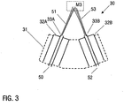
- Fig. 3 is a schematic representation of a device according to a third embodiment of the invention. Parts that are similar to the first and / or second exemplary embodiment or identical parts are provided with similar or identical reference numerals, so that reference can be made to the description of the first and / or second exemplary embodiment in order to avoid repetitions.
- Fig. 3 shows an application device 30. Similar to the first and second exemplary embodiments, the application device 30 comprises an application element 31.
- the application element 31 is preferably an application tube which, in terms of flow technology, essentially represents an end section of the device or of the application device 30.
- the application element 31 has not only one nozzle, but two nozzles 32A and 32B.
- the first nozzle 32A has a first outlet opening 33A and the second nozzle 32B has a second outlet opening 33B.
- a preservative line 50 for supplying a preservative 51 to the application device 30 and a hardener line 52 for supplying a hardener 53 to the application device 30 are provided.
- the preservative line 50 leads to the first nozzle 32A or the first outlet opening 33A, so that the preservative 51 can be conveyed out of the first outlet opening 33A.
- the hardener line 52 leads to the second nozzle 32B or the second outlet opening 33B, so that the hardener 53 can be conveyed out of the second outlet opening 33B.
- the first and second nozzles 32A and 32B or the first and second outlet openings 33A and 33B are arranged and / or can be positioned such that the preservative 51 and the hardener 53 are mixed outside the application element 31 in the region M3 shown schematically.
- the preservative 51 and the hardener 53 are thus mixed in flight and / or on the surface to be preserved.
- Fig. 4 is a schematic representation of a device according to a fourth embodiment, which is arranged along a conveying path F for motor vehicle body components. Parts that are similar to the first, second and / or third exemplary embodiment or identical parts are provided with similar or identical reference numerals, so that reference can be made to the descriptions of this exemplary embodiment in order to avoid repetitions.
- Fig. 4 essentially an application device 40 can be seen, which is shown on the one hand on robots R1, R2 and on the other hand in an enlarged representation.
- the application device 40 has two separate application elements 41A and 41B, which can preferably each be an application tube.
- the application element 41A and the application element 41B each represent essentially end sections of the device or of the application device 40 in terms of flow technology.
- the first application element 41A can be on a robot arm of a robot R1, preferably on the latter free end, whereas the second application element 41B can be arranged on a robot arm of another robot R2, preferably at its free end.
- the first application element 41A comprises a first nozzle 42A, at which a first outlet opening 43A is provided.
- the second application element 41B comprises a second nozzle 42B, at which a second outlet opening 43B is provided.
- a preservative line 50 for supplying a preservative 51 to the application device 40 and a hardener line 52 for supplying a hardener 53 to the application device 40 are provided.
- the preservative line 50 opens out at the first nozzle 42A or the first outlet opening 43A, so that the preservative 51 can be conveyed out of the first outlet opening 43A.
- the hardener line 52 opens at the second nozzle 42B or the second outlet opening 43B, so that the hardener 53 can be conveyed out of the second outlet opening 43B.
- the device for cavity preservation according to the fourth exemplary embodiment is preferably arranged on the conveyor path F for transporting motor vehicle body components.
- the first application element 41A can then be provided in a preservative application station S1, and the second application element 41B can be provided in a hardener application station S2.
- the hardener application station S2 could be positioned directly after the preservative application station S1.
- the material in particular the preservative and the hardener, could preferably be coordinated with one another in such a way that only a defined period of time is possible after the hardener has been introduced.
- the run should be stopped very quickly ("drop stop").
- the hardener application station S2 could also be positioned away from the preservative application station S1 in accordance with the process time of penetration. The hardener could then react without delay to trigger the "drop stop".
- the first and second nozzles 42A and 42B or the first and second outlet openings 43A and 43B are provided in such a way that the preservative 51 and the hardener 53 can be mixed outside the application device 40.
- the preservative 51 and hardener 53 are delivered sequentially, i.e. in a first step the first application element 41A applies the preservative 51 to the component to be preserved and in a second step the second application element 41B applies the hardener 53 to the component to be preserved.
- the preservative 51 and the hardener 53 are therefore preferably mixed on the component to be preserved.
- the application device can thus have one application element or a plurality of application elements.
- the application device preferably represents essentially an end section of the device in terms of flow technology.
- the application element or elements are preferably arranged behind the application device in terms of flow technology or preferably represent an essentially end section of the application device in terms of flow technology.
- the or the application elements are preferably designed such that they have one or can position several outlet openings on hard-to-access areas to be preserved, e.g. cavities to be preserved, undercuts, etc.
- means for atomizing the preservative and / or the hardener can be provided, for example in the published patent application DE 103 22 170 A1 is described, so that the content of this publication is fully attributable to the present description.
- the invention is preferably applicable to manual systems, semi-automatic systems, robot systems, waxing machines, etc.
- manual or semi-automatic systems a worker guides the corresponding nozzle (s) or outlet opening (s) into the cavity to be preserved and starts the coating process manually.
- the amount of material can be dosed automatically.
- the nozzle is brought to the next opening and the process is repeated.
- Different nozzles and material quantities as well as the other process parameters for different components on the vehicle are often different.
- a controller can preferably provide information with regard to the nozzle (s) to be used, whether and when the nozzle should be changed, the setting of relevant parameters, etc. After the removal (start), the coating can run fully automatically.
- Robotic systems are mostly used where a high degree of flexibility is required, e.g. Body variants, low quantities, changes, etc.
- the robots preferably have interchangeable heads, with one or more nozzles per head, which receive the nozzle heads according to the body opening and bring them into the corresponding body openings.
- the coating can run fully automatically.
- the body of waxing machines is usually positioned mechanically (centered). Then the nozzle (s) is inserted into the body openings by means of a mechanism and the wax is applied.
Landscapes
- Chemical & Material Sciences (AREA)
- Chemical Kinetics & Catalysis (AREA)
- Coating Apparatus (AREA)
- Nozzles (AREA)
- Application Of Or Painting With Fluid Materials (AREA)
Description
- Die Erfindung betrifft eine Vorrichtung und ein Verfahren zur Hohlraumkonservierung von Kraftfahrzeugkarosseriebauteilen mit einem Konservierungsmittel gemäß den Ansprüchen 1 und 6. Vorzugsweise findet die Erfindung Anwendung bei der Konservierung schwer zugänglicher, zu konservierender Flächen, was neben Hohlraumkonservierungen z.B. auch auf Nahtabdichtungen (z.B. Bördelnähte), etc. von Kraftfahrzeugkarosseriebauteilen zutrifft.
- Die Hohlraumkonservierung, d.h. die Konservierung einer Innenfläche eines Hohlraums, wird meist bei hochwertigen Fahrzeugen eingesetzt, um den Korrosionsschutz deutlich zu verlängern. Typisch ist der Einsatz der Hohlraumkonservierung insbesondere in Ländern, in denen hohe Zusagen betreffend die sogenannte "Durchrostgarantie" (Korrosionsschutzgarantie) gemacht werden, was insbesondere auf viele Länder Europas zutrifft. Manche in solche Länder importierten Fahrzeuge werden, sofern sie nicht bereits einer Hohlraumkonservierung unterzogen wurden, nachträglich einer Hohlraumkonservierung unterzogen.
- Insbesondere bei hochwertigen Fahrzeugen mit hohen Korrosionsschutzgarantien kann bisher auf eine Hohlraumkonservierung nicht verzichtet werden.
- Zur Hohlraumkonservierung von Kraftfahrzeugkarosserien sind im Wesentlichen zwei Verfahren bekannt, nämlich das Flutverfahren und das Sprühverfahren.
- Beim Flutverfahren werden die zu konservierenden Hohlräume der Kraftfahrzeugkarosserie mit lösemittelfreiem und durch Erhitzen verflüssigtem Wachs ausgegossen, wobei sich ein Teil des Wachses an den Hohlraumwandungen ablagert und diese dadurch konserviert, während das überschüssige Wachs abläuft.
- Bei dem Sprühverfahren zur Hohlraumkonservierung wird das als Konservierungsmittel dienende Wachs dagegen auf die Innenwandungen der Hohlräume aufgesprüht, wozu beispielsweise ein Applikationsrohr (Lanze) verwendet werden kann, das von außen in die Hohlräume eingeführt wird und Austrittsöffnungen für das Wachs aufweist.
- Als Material zur Hohlraumkonservierung wird üblicherweise ein Wachs verwendet. Gemäß Stand der Technik ist eine Verarbeitung typisch, bei der das Wachs in einer Vorzerstäubungskammer zusammen mit Luft vorzerstäubt und mittels Luft durch Schläuche (z.B. 3-8m Länge) zur Karosse geleitet wird. Die Luft dient der Zerstäubung, dem Transport und der Verteilung im Hohlraum. Das Wachs wird in den Hohlraum eingebracht und soll diesen üblicherweise versiegeln. Dazu muss es verlaufen. Unterstützt wird dies meist durch eine Kippstation, die das Karosserieteil "kippt", um so den Verlauf (Penetration) des Wachses zu unterstützen. Öffnungen (Auslaufbohrungen) in dem zu konservierenden Karosserieteil zeigen an, dass der Hohlraum erfolgreich beschichtet ist.
- Nachteilig daran ist, dass auslaufendes Wachs unerwünscht ist, insbesondere folgende Förderbereiche verschmutzen kann.
- Dieser Nachteil wird durch Bereitstellung eines Wachstrockners minimiert. Dieser Wachstrockner heizt die Karosserieteile auf eine bestimmte Mindesttemperatur über eine bestimmte Mindestzeit, z.B. 1 min. bei 60°C. Eine übliche Wachstrocknerlänge beträgt z.B. 60 m. Nach dem Trocknungsvorgang ist das Auslaufen von Wachs im Wesentlichen gestoppt. Man spricht in diesem Zusammenhang auch vom sogenannten "Drop-Stop". Das Wachs härtet noch weitere Tage/Wochen nach, wird aber nie ganz fest, sondern bleibt flexibel. Derartige Wachstrockner gehen mit einer Reihe von Nachteilen einher, wie z.B. hoher Energieverbrauch im Betrieb, hohe Investitions- und/oder Instandhaltungskosten, hoher Reinigungsaufwand, großer Platzverbrauch, fehlende Nachrüstbarkeit bei vielen Kunden, etc.
-
DE 10 2008 011 489 A1 offenbart ein Verfahren zur Hohlraumversiegelung eines Kraftfahrzeugbauteils durch Einsprühen eines aushärtbaren Konservierungsmittels wie z. B. Wachs, dem eine vernetzende Komponente direkt vor dem Einsprühen zugegeben werden kann. Zur Applikation des Konservierungsmittels ist eine als an sich bekannt bezeichnete Sprühpistole vorgesehen, die mit einem Applikationselement in den zu konservierenden Hohlraum eingreift. Die vernetzende Komponente wird in einer Mischkammer mit dem Konservierungsmittel gemischt. -
DE 103 20 341 A1 offenbart ein Verfahren zum Ausbilden eines Polyurethanartikels, wobei ein erster und ein zweiter Grundstoff eines Polyurethansystems in einen unbegrenzten Raum über einer Form gespritzt wird.US 5 071 683 A offenbart ein ähnliches Verfahren zum Herstellen einer Elastomerpolyurethanschicht in einer Form.GB 2 251 396 A - Die Dokumente
DE 35 18 584 A1 ,EP 2 067 530 A1 ,DE 36 16 235 C2 ,EP 1 795 282 A1 ,DE 31 42 154 C2 ,EP 2 098 302 A1 undUS 4 703 894 A beschreiben weiteren technologischen Hintergrund betreffend die Erfindung. - Aufgabe der Erfindung ist es, eine verbesserte Vorrichtung und ein verbessertes Verfahren zur Konservierung von Bauteilen zu schaffen. Insbesondere soll es möglich sein, nach der Applikation des Konservierungsmittels und optional anschließend erfolgender Penetration in kurzer Zeit und/oder ohne Trockner bzw. Ofen einen "Drop-Stop" zu erzielen. Bei der Hohlraumskonservierung beispielsweise soll auf einfache Art und Weise verhindert werden können, dass Konservierungsmittel aus dem zu konservierenden Hohlraum gelangt.
- Diese Aufgabe wird mit den Merkmalen der unabhängigen Ansprüche gelöst.
- Die Erfindung umfasst die allgemeine technische Lehre, ein Konservierungsmittel und einen Härter bei der Konservierung von Bauteilen zu mischen, um das Konservierungsmittel schneller aushärten zu lassen, insbesondere, um einen "Drop-Stop" zu erzielen.
- Die erfindungsgemäße Vorrichtung zur Konservierung von Bauteilen mit einem Konservierungsmittel zeichnet sich insbesondere dadurch aus, dass zusätzlich zu dem Konservierungsmittel ein Härter appliziert wird, der mit dem Konservierungsmittel reagiert, um das Konservierungsmittel aushärten zu lassen. Die Vorrichtung ist somit vorzugsweise vorgesehen, um zusätzlich zu dem Konservierungsmittel einen Härter zu applizieren, um mit dem Konservierungsmittel zu reagieren, wodurch eine Aushärtung des Konservierungsmittels erzielbar ist.
- Vorteilhaft ist daran insbesondere, dass zur Erzielung eines "Drop-Stops" kein Trockner bzw. Ofen erforderlich ist.
- Ein weiterer Vorteil der Erfindung liegt darin, dass die Vorrichtung so ausgebildet werden kann, dass keine oder nur sehr wenige Abschnitte der Vorrichtung mit einem Gemisch aus Konservierungsmittel und Härter in Kontakt kommen. Das Konservierungsmittel härtet durch den Härter ab dem Mischvorgang aus. Ein üblicher Mischer kann aus Platzgründen nicht direkt in der Düse sitzen, sondern müsste einige Zentimeter bis Meter von der Düse entfernt angebaut werden. Da der Härter mit Wasser reagiert, reicht das Wasser oder die Restfeuchte aus der Luft/Druckluft aus, um eine Reaktion in Gang zu setzen. Durch den Prozess des Leerblasens der Zuführleitung nach dem Vorzerstäuben und/oder Mischen würden Reste in der Zuführleitung verbleiben, die auch bei nachfolgenden Beschichtungsvorgängen nicht mehr vollständig ausgetragen werden würden. Auch durch ein Spülen würde die Zuführleitung und andere kontaminierten Vorrichtungsteile nicht zu 100% sauber. Somit würden Rückstände verbleiben, die aushärten, was mit einer Reihe von Problemen einhergeht. Als besonders problematisch sind hervorzuheben: Verstopfen der Düsen, Verändern der Düsengeometrie durch Ablagerungen, Veränderung des Applikationsergebnisses, Fehlfunktion/Ausfall einzelner Komponenten (z.B. Ventile), Druckverluste, Undichtigkeiten an Schnittstellen (z.B. zu Wechselköpfen), etc. Ferner können Verschmutzungen von Außengeometrien durch das Zerstäuben auftreten, wobei insbesondere Düsen, Düsenrohre, Wechselköpfe, Roboterbauteile, etc. betroffen sein können. Obige Probleme führen zu erhöhtem Reinigungs- und Instandhaltungsaufwand.
- Gemäß der Erfindung kann das Mischen von Konservierungsmittel und Härter vorzugsweise strömungstechnisch an einem Endabschnitt der Vorrichtung erfolgen, wie beispielsweise in einer Applikationseinrichtung, einem Applikationselement und/oder einer Düse. Es besteht auch die Möglichkeit, die Vorrichtung so auszubilden, dass sich das Konservierungsmittel und der Härter im Flug (in der Luft), in einem zu konservierenden Hohlraum und/oder an einem zu konservierenden Bauteil mischen. Vorzugsweise erfolgt die Initiierung der Vermischung somit in einer Applikationseinrichtung, einem Applikationselement, einer Düse, im Flug (in der Luft), in einem zu konservierenden Hohlraum und/oder an einem zu konservierenden Bauteil. Folglich kommt es vorzugsweise zu keiner Vermischung von Konservierungsmittel und Härter vor der Applikationseinrichtung, vor dem Applikationselement, vor einer Düse und/ oder vor einer Austrittsöffnung einer Düse. Somit können obige Nachteile völlig vermieden, zumindest aber deutlich abgeschwächt werden.
- Erfindungsgemäß umfasst die Vorrichtung eine Applikationseinrichtung zum Applizieren des Konservierungsmittels und des Härters auf das zu konservierende Bauteil, eine Konservierungsmittelleitung zum Zuführen des Konservierungsmittels zu der Applikationseinrichtung und eine Härterleitung zum Zuführen des Härters zu der Applikationseinrichtung
- Die Applikationseinrichtung weist erfindungsgemäß ein Applikationselement mit einer Austrittsöffnung auf Das Applikationselement kann beispielsweise ein Applikationsrohr, eine Lanze, eine Sonde, etc. sein.
- Bei einem bevorzugten Ausführungsbeispiel hat das Applikationselement eine Düse, an der die Austrittsöffnung bereitgestellt ist. Erfindungsgemäß münden die Konservierungsmittelleitung und die Härterleitung so in das Applikationselement, dass sich das Konservierungsmittel und der Härter in dem Applikationselement mischen. Der Mischvorgang kann somit in dem Applikationselement initiiert werden. Vorteilhaft daran ist, dass nur wenige Abschnitte mit einem Gemisch aus Konservierungsmittel und Härter in Kontakt kommen.
- Erfindungsgemäß besteht auch die Möglichkeit, dass die Konservierungsmittelleitung und die Härterleitung so in das Applikationselement münden, dass sich das Konservierungsmittel und der Härter unmittelbar vor der ersten Düse und/oder in der Düse mischen. Der Mischvorgang kann somit unmittelbar vor und/oder in der Düse initiiert werden. Vorteilhaft daran ist, dass nur wenige Abschnitte mit einem Gemisch aus Konservierungsmittel und Härter in Kontakt kommen. Das Applikationselement ist z.B. so ausgebildet, dass es durch eine Öffnung in einen zu konservierenden Hohlraum geführt werden kann, um dessen zu konservierende Innenflächen mit Konservierungsmittel und Härter zu besprühen.
- Ferner besteht die Möglichkeit, einen Mischer bereitzustellen, insbesondere in der Applikationseinrichtung, einem Applikationselement, vorzugsweise einem Applikationsrohr, und/oder in einer Düse. Der Mischer kann sich auch über zumindest zwei der vorgenannten Abschnitte erstrecken (z.B. vom Applikationsrohr in die Düse). Um den Mischer z.B. in der Düse und/oder im Applikationsrohr unterzubringen, muss der Mischer entsprechend kleine Ausmaße aufweisen, und dennoch ausreichende Mischerergebnisse erzielen, wozu herkömmliche Mischer nicht in der Lage sind. Ein für die Erfindung geeigneter Mischer könnte vorzugsweise hergestellt werden mittels generativer Verfahren (z.B. Rapid-Prototyping).
- Weiterhin können Mittel bereitgestellt sein, um insbesondere die Applikationseinrichtung, das Applikationselement und/oder die Düse mit einem Löse-/Spülmittel, einer reaktiven Substanz (z.B. einem Reaktionsverzögerer, wie beispielsweise einem organischen Säurechlorid), die das Aushärten im Wesentlichen stoppt oder hemmt, und/oder einer monofunktionellen Substanz (z.B. Propanol oder Butanol, insbesondere im Falle einer Isocyanatfunktionalität), die mit dem Konservierungsmittel und/oder dem Härter reagiert, um ein Aushärten im Wesentlichen zu stoppen oder zu hemmen (insbesondere, indem deren Kettenreaktion im Wesentlichen unterbunden wird), zu durchströmen, zu beschichten und/oder zu befüllen. Die reaktive Substanz und/oder die monofunktionelle Substanz wirken somit als Blockierungsmittel, um ein Aushärten des Konservierungsmittels bzw. des Gemischs, umfassend Konservierungsmittel und Härter, zu verzögern, vorzugsweise im Wesentlichen zu verhindern. Es ist möglich, dass das Gemisch weitere Bestandteile wie z.B. ein Löse- und/oder Spülmittel umfasst.
- Bei der monofunktionellen Substanz handelt es sich vorzugsweise um einen reaktiven, monofunktionellen Stoff, der mit einer Konservierungsmittelkomponente und/oder einer Härterkomponente, vorzugsweise mit einer Härterkomponente, reagiert, dabei aber auf Grund seiner Monofunktionalität nicht zu Polymerketten führt, sondern im Idealfall zu einem Molekül bzw. Oligomer aus einem Härtermolekül und zwei Blockierungsmittelmolekülen. Als monofunktionelle Substanz kommen insbesondere Amine oder Alkohole, bevorzugt niedere Alkohole, wie z.B. Ethanol, Propanol, Butanol und/oder deren Isomere in Betracht. Die Reaktivität der Kettenreaktion, die durch die monofunktionelle Substanz im Wesentlichen unterbunden wird, sollte höher sein als die der Ketten-bildenden Reaktion. Dadurch, dass z.B. die bi- oder multifunktionellen Härtermoleküle mit einem kurzkettigen monofunktionellen Molekül reagieren, bleibt die Viskosität der Mischung (Konservierungsmittel, Härter, monofunktionelle Substanz) niedrig.
- Die reaktive Substanz soll als solche nicht in die zu konservierenden Hohlräume gelangen.
- Es besteht auch die Möglichkeit, die Applikationseinrichtung an nur einem Roboter, vorzugsweise an nur einem einzigen Roboterarm, anzuordnen. Beispielsweise könnte der Roboter entlang eines Förderwegs für Kraftfahrzeugkarosseriebauteile positioniert sein. Die Erfindung ist hierauf jedoch nicht beschränkt, sondern kann z.B. auch bei handgeführten Vorrichtungen, halbautomatischen Anlagen, Roboteranlagen, Wachsmaschinen, etc. zum Einsatz kommen.
- Ferner können Mittel bereitgestellt sein, um das Konservierungsmittel und/oder den Härter zu zerstäuben.
- Üblicherweise weist ein zu konservierender Hohlraum zumindest eine Öffnung auf, aus der das eingeführte Konservierungsmittel unerwünscht wieder entweichen kann. Die Erfindung eröffnet die Möglichkeit, diese Öffnung mittels dem Konservierungsmittel und dem Härter zu schließen. Vorzugsweise wird dazu das Konservierungsmittel (mit und/oder ohne Härter) in den zu konservierenden Hohlraum befördert. Dann wird insbesondere gezielt der Bereich um die Öffnung mit dem Härter versehen. Als Vorteil dieser Variante ist vor allem die Einsparung von Härter zu nennen. Es ist auch möglich, gezielt die Bereiche um die Öffnung mit Härter zu versehen, ohne das Erfordernis, dass sich die Öffnung schließt.
- Alternativ kann die in dem zu konservierenden Hohlraum befindliche Öffnung auch mittels eines Pfropfs geschlossen werden. Der Pfropf kann vorzugsweise aus Metall, Kunststoff, Gummi, Wachs oder einem sich auflösenden Material (z.B. wasserlösliche Teile, Eis, etc.) sein, das sich auflöst, nachdem das Konservierungsmittel getrocknet ist.
- Ferner umfasst die Erfindung auch ein Verfahren zur Hohlraumkonservierung von Kraftfahrzeugkarosseriebauteilen mit einer Vorrichtung gemäß der Erfindung, mit dem die vorstehend beschriebenen Vorteile erzielbar sind.
- Das Verfahren zeichnet sich insbesondere dadurch aus, dass zusätzlich zu dem Konservierungsmittel ein Härter auf das zu konservierende Bauteil appliziert wird, der mit dem Konservierungsmittel reagiert, um das Konservierungsmittel aushärten zu lassen.
- Als Konservierungsmittel kann z.B. ein Wachs verwendet werden, wohingegen als Härter z.B. Isocyanat verwendet werden kann. Die Erfindung kann aber auch mit anderen Komponenten, wie z.B. verschiedenen Lacken verwendet werden.
- Andere vorteilhafte Weiterbildungen der Erfindung sind in den Unteransprüchen offenbart oder ergeben sich aus der nachstehenden Beschreibung bevorzugter Ausführungsbeispiele in Verbindung mit den beigefügten Figuren, wobei allerdings in den
Figuren 2 ,3 und4 keine Vorrichtung gemäß den Ansprüchen 1 und 6 dargestellt ist. Es zeigen: - Fig. 1
- eine schematische Darstellung einer Vorrichtung zur Konservierung von Bauteilen gemäß einem ersten Ausführungsbeispiel;
- Fig. 2
- eine schematische Darstellung einer Vorrichtung zur Konservierung von Bauteilen gemäß einem zweiten Ausführungsbeispiel;
- Fig. 3
- eine schematische Darstellung einer Vorrichtung zur Konservierung von Bauteilen gemäß einem dritten Ausführungsbeispiel;
- Fig. 4
- eine schematische Darstellung einer Vorrichtung zur Konservierung von Bauteilen gemäß einem vierten Ausführungsbeispiel.
-
Fig. 1 ist eine schematische Darstellung einer Vorrichtung zur Konservierung von Bauteilen gemäß einem ersten Ausführungsbeispiel, vorzugsweise zur Konservierung einer Innenfläche eines Hohlraums. Die Vorrichtung ist ausgelegt, um zusätzlich zu einem Konservierungsmittel einen Härter auf das zu konservierende Bauteil zu applizieren, der mit dem Konservierungsmittel reagiert, was das Konservierungsmittel aushärten lässt. - Dargestellt in
Fig. 1 ist insbesondere eine Applikationseinrichtung 10. Die Applikationseinrichtung 10 kann an einem Roboterarm (nicht dargestellt), vorzugsweise am freien Ende des Roboterarms, angeordnet sein. - Gemäß dem ersten Ausführungsbeispiel umfasst die Applikationseinrichtung 10 ein Applikationselement 11. Das Applikationselement 11 ist vorzugsweise ein Applikationsrohr, das strömungstechnisch im Wesentlichen einen Endabschnitt der Vorrichtung bzw. der Applikationseinrichtung 10 darstellt.
- An dem Applikationselement 11 ist eine Düse 12 bereitgestellt. An der Düse 12 ist eine Austrittsöffnung 13 vorgesehen. Ferner sind eine Konservierungsmittelleitung 50 zum Zuführen eines Konservierungsmittels 51 (z.B. Wachs) zu der Applikationseinrichtung 10 und eine Härterleitung 52 zum Zuführen eines Härters (z.B. Isocyanat) 53 zu der Applikationseinrichtung 10 bereitgestellt.
- Bei dem ersten Ausführungsbeispiel münden (öffnen sich) die Konservierungsmittelleitung 50 und die Härterleitung 52 in dem Applikationselement 11, vorzugsweise in der an dem Applikationselement 11 vorgesehenen Düse 12. Ein Mischen des Konservierungsmittels 51 und des Härters 53 erfolgt somit im Applikationselement 11, d.h. dass das Mischen des Konservierungsmittels 51 und des Härters 53 in dem Applikationselement 11 initiiert wird. M1 kennzeichnet diesen Mischbereich innerhalb des Applikationselements 11. Vorzugsweise kommt es zu keinem Mischen von Konservierungsmittel 51 und Härter 53 vor dem Applikationselement 11.
- Wie in
Fig. 1 zu sehen, münden die Konservierungsmittelleitung 50 und die Härterleitung 52 in der Düse 12, die an dem Applikationselement 11 vorgesehen ist, so dass im ersten Ausführungsbeispiel ein Mischen des Konservierungsmittels 51 und des Härters 53 in der Düse 12 erfolgt. - Es ist auch möglich, dass die Konservierungsmittelleitung 50 und die Härterleitung 52 vor, insbesondere unmittelbar vor der Düse 12 münden, so dass ein Mischen von Konservierungsmittel 51 und Härter 53 in dem Applikationselement 11, vorzugsweise einem Applikationsrohr, und der Düse 12 erfolgt.
- In dem Applikationselement 11 und/oder der Düse 12 kann bei Bedarf ein Minimischer angeordnet werden.
-
Fig. 2 ist eine schematische Darstellung einer Vorrichtung gemäß einem zweiten Ausführungsbeispiel der Erfindung. Zum ersten Ausführungsbeispiel ähnliche Teile oder identische Teile sind mit ähnlichen oder identischen Bezugszeichen versehen, so dass auf die Beschreibung zum ersten Ausführungsbeispiel verwiesen werden kann, um Wiederholungen zu vermeiden. - Dargestellt in
Fig. 2 ist insbesondere eine Applikationseinrichtung 20. Gemäß dem zweiten Ausführungsbeispiel umfasst die Applikationseinrichtung 20 ein Applikationselement 21. Das Applikationselement 21 ist vorzugsweise ein Applikationsrohr, das strömungstechnisch im Wesentlichen einen Endabschnitt der Vorrichtung bzw. der Applikationseinrichtung 20 darstellt. - An dem Applikationselement 21 ist eine Düse 22 bereitgestellt. An der Düse 22 sind zwei Austrittsöffnungen 23A und 23B vorgesehen. Ferner sind eine Konservierungsmittelleitung 50 zum Zuführen eines Konservierungsmittels 51 zu der Applikationseinrichtung 20 und eine Härterleitung 52 zum Zuführen eines Härters 53 zu der Applikationseinrichtung 20 bereitgestellt.
- Bei dem zweiten Ausführungsbeispiel führt die Konservierungsmittelleitung 50 zu der ersten Austrittsöffnung 23A und die Härterleitung 52 führt zu der zweiten Austrittsöffnung 23B.
- Die Düse 22 bzw. die erste und zweite Austrittsöffnung 23A und 23B sind so angeordnet und/oder so positionierbar, dass ein Mischen des Konservierungsmittels 51 und des Härters 53 außerhalb des Applikationselements 22 in dem schematisch dargestellten Bereich M2 erfolgt.
- Das Mischen des Konservierungsmittels 51 und des Härters 53 erfolgt somit im Flug und/oder an einer zu konservierenden Fläche.
-
Fig. 3 ist eine schematische Darstellung einer Vorrichtung gemäß einem dritten Ausführungsbeispiel der Erfindung. Zum ersten und/oder zweiten Ausführungsbeispiel ähnliche Teile oder identische Teile sind mit ähnlichen oder identischen Bezugszeichen versehen, so dass auf die Beschreibung zum ersten und/oder zweiten Ausführungsbeispiel verwiesen werden kann, um Wiederholungen zu vermeiden. -
Fig. 3 zeigt eine Applikationseinrichtung 30. Ähnlich wie bei dem ersten und zweiten Ausführungsbeispiel umfasst die Applikationsvorrichtung 30 ein Applikationselement 31. Das Applikationselement 31 ist vorzugsweise ein Applikationsrohr, das strömungstechnisch im Wesentlichen einen Endabschnitt der Vorrichtung bzw. der Applikationseinrichtung 30 darstellt. - Das Applikationselement 31 weist jedoch nicht nur eine Düse, sondern zwei Düsen 32A und 32B auf. Die erste Düse 32A hat eine erste Austrittsöffnung 33A und die zweite Düse 32B hat eine zweite Austrittsöffnung 33B.
- Ferner sind eine Konservierungsmittelleitung 50 zum Zuführen eines Konservierungsmittels 51 zu der Applikationseinrichtung 30 und eine Härterleitung 52 zum Zuführen eines Härters 53 zu der Applikationseinrichtung 30 bereitgestellt.
- Bei dem dritten Ausführungsbeispiel führt die Konservierungsmittelleitung 50 zu der ersten Düse 32A bzw. der ersten Austrittsöffnung 33A, so dass das Konservierungsmittel 51 aus der ersten Austrittsöffnung 33A befördert werden kann. Die Härterleitung 52 führt zu der zweiten Düse 32B bzw. der zweiten Austrittsöffnung 33B, so dass der Härter 53 aus der zweiten Austrittsöffnung 33B befördert werden kann.
- Die erste und zweite Düse 32A und 32B bzw. die erste und zweite Austrittsöffnung 33A und 33B sind so angeordnet und/oder sind so positionierbar, dass ein Mischen des Konservierungsmittels 51 und des Härters 53 außerhalb des Applikationselements 31 in dem schematisch dargestellten Bereich M3 erfolgt.
- Das Mischen des Konservierungsmittels 51 und des Härters 53 erfolgt somit im Flug und/oder an der zu konservierenden Fläche.
-
Fig. 4 ist eine schematische Darstellung einer Vorrichtung gemäß einem vierten Ausführungsbeispiel, die entlang eines Förderwegs F für Kraftfahrzeugkarosseriebauteile angeordnet ist. Zum ersten, zweiten und/oder dritten Ausführungsbeispiel ähnliche Teile oder identische Teile sind mit ähnlichen oder identischen Bezugszeichen versehen, so dass auf die Beschreibungen zu diesen Ausführungsbeispiel verwiesen werden kann, um Wiederholungen zu vermeiden. - In
Fig. 4 ist im Wesentlichen eine Applikationseinrichtung 40 zu sehen, die einerseits an Robotern R1, R2 und andererseits in vergrößerter Darstellung gezeigt ist. Im Gegensatz zu den vorigen Ausführungsbeispielen weist die Applikationseinrichtung 40 zwei separate Applikationselemente 41A und 41B auf, bei denen es sich vorzugsweise jeweils um ein Applikationsrohr handeln kann. Das Applikationselement 41A und das Applikationselement 41B stellen jeweils strömungstechnisch im Wesentlichen Endabschnitte der Vorrichtung bzw. der Applikationseinrichtung 40 dar. - Das erste Applikationselement 41A kann an einem Roboterarm eines Roboters R1, vorzugsweise an dessen freien Ende, angeordnet sein, wohingegen das zweite Applikationselement 41B an einem Roboterarm eines anderen Roboters R2, vorzugsweise an dessen freien Ende, angeordnet sein kann.
- Das erste Applikationselement 41A umfasst eine erste Düse 42A, an der eine erste Austrittsöffnung 43A bereitgestellt ist. Das zweite Applikationselement 41B umfasst eine zweite Düse 42B, an der eine zweite Austrittsöffnung 43B bereitgestellt ist.
- Ferner sind eine Konservierungsmittelleitung 50 zum Zuführen eines Konservierungsmittels 51 zu der Applikationseinrichtung 40 und eine Härterleitung 52 zum Zuführen eines Härters 53 zu der Applikationseinrichtung 40 bereitgestellt.
- Bei dem vierten Ausführungsbeispiel mündet die Konservierungsmittelleitung 50 an der ersten Düse 42A bzw. der ersten Austrittsöffnung 43A, so dass das Konservierungsmittel 51 aus der ersten Austrittsöffnung 43A befördert werden kann. Die Härterleitung 52 mündet an der zweiten Düse 42B bzw. der zweiten Austrittsöffnung 43B, so dass der Härter 53 aus der zweiten Austrittsöffnung 43B befördert werden kann.
- Vorzugsweise wird die Vorrichtung zur Hohlraumkonservierung gemäß dem vierten Ausführungsbeispiel an dem Förderweg F zum Transportieren von Kraftfahrzeugkarosseriebauteilen angeordnet. Das erste Applikationselement 41A kann dann in einer Konservierungsmittelapplizierstation S1 bereitgestellt sein, und das zweite Applikationselement 41B kann in einer Härterapplizierstation S2 bereitgestellt sein. Dabei könnte die Härterapplizierstation S2 direkt nach der Konservierungsmittelapplizierstation S1 positioniert sein.
- Vorzugsweise könnte das Material, insbesondere das Konservierungsmittel und der Härter, so aufeinander abgestimmt sein, dass nur noch eine definierte Verlaufszeit nach dem Einbringen des Härters möglich ist. Nachdem das Konservierungsmittel, vorzugsweise ein Wachs, penetriert ist, soll das Verlaufen sehr schnell gestoppt werden ("Drop-Stop"). Die Härterapplizierstation S2 könnte aber auch entsprechend der Prozesszeit des Penetrierens entfernt von der Konservierungsmittelapplizierstation S1 positioniert sein. Der Härter könnte dann ohne Verzögerung reagieren, um den "Drop-Stop" auszulösen.
- Die erste und zweite Düse 42A und 42B bzw. die erste und zweite Austrittsöffnung 43A und 43B werden so bereitgestellt, dass ein Mischen des Konservierungsmittels 51 und des Härters 53 außerhalb der Applikationseinrichtung 40 erfolgen kann.
- Vorzugsweise erfolgt die Abgabe von Konservierungsmittel 51 und Härter 53 sequentiell, d.h. in einem ersten Schritt appliziert das erste Applikationselement 41A das Konservierungsmittel 51 auf das zu konservierende Bauteil und in einem zweiten Schritt appliziert das zweite Applikationselement 41B den Härter 53 auf das zu konservierende Bauteil. Das Mischen des Konservierungsmittels 51 und des Härters 53 erfolgt somit vorzugsweise an dem zu konservierenden Bauteil.
- Die Applikationseinrichtung kann somit ein Applikationselement oder mehrere Applikationselemente aufweisen. Die Applikationseinrichtung stellt vorzugsweise strömungstechnisch im Wesentlichen einen Endabschnitt der Vorrichtung dar. Das oder die Applikationselemente sind vorzugsweise strömungstechnisch hinter der Applikationseinrichtung angeordnet bzw. stellen vorzugsweise strömungstechnisch einen im Wesentlichen Endabschnitt der Applikationseinrichtung dar. Das oder die Applikationselemente sind vorzugsweise so ausgebildet, dass sie eine oder mehrere Austrittsöffnungen an schwer zugängliche, zu konservierende Flächen positionieren können, wie z.B. zu konservierende Hohlräume, Hinterschneidungen, etc.
- Gemäß der Erfindung können Mittel zur Zerstäubung des Konservierungsmittels und/oder des Härters bereitgestellt sein, was beispielsweise in der Offenlegungsschrift
DE 103 22 170 A1 beschrieben ist, so dass der Inhalt dieser Offenlegungsschrift der vorliegenden Beschreibung in vollem Umfang zuzurechnen ist. - Die Erfindung ist vorzugsweise bei Handanlagen, halbautomatischen Anlagen, Roboteranlagen, Wachsmaschinen, etc. anwendbar. Bei den Handanlagen bzw. halbautomatischen Anlagen führt ein Werker die entsprechende Düse(n) bzw. Austrittsöffnung(en) in den zu konservierenden Hohlraum und startet manuell den Beschichtungsvorgang. Die Materialmenge kann dabei automatisch dosiert werden. Nach Ablauf des Vorgangs wird die Düse zur nächsten Öffnung gebracht und der Vorgang wiederholt sich. Oft sind unterschiedliche Düsen und Materialmengen sowie die weiteren Prozessparameter für verschiedene Bauteile am Fahrzeug unterschiedlich. Vorzugsweise kann eine Steuerung Informationen bereitstellen im Hinblick auf die einzusetzende(n) Düse(n), ob und wann die Düse gewechselt werden sollte, die Einstellung relevanter Parameter, etc. Nach dem Abziehen (Start) kann die Beschichtung vollautomatisch ablaufen.
- Roboteranlagen werden meist dort eingesetzt, wo ein hohes Maß an Flexibilität erforderlich ist, wie z.B. Karossenvarianten, niedrige Stückzahlen, Änderungen, etc. Die Roboter haben vorzugsweise Wechselköpfe, mit einer oder mehreren Düsen pro Kopf, die entsprechend der Karosserieöffnung die Düsenköpfe aufnehmen und in die entsprechenden Karosserieöffnungen bringen. Die Beschichtung kann vollautomatisch ablaufen.
- Bei Wachsmaschinen wird die Karosse meist mechanisch positioniert (zentriert). Dann wird mittels einer Mechanik die Düse(n) in die Karossenöffnungen eingeführt und das Wachs appliziert. Diese Anlagen arbeiten vollautomatisch
- Die Erfindung ist nicht auf die vorstehend beschriebenen bevorzugten Ausführungsbeispiele beschränkt. Vielmehr ist eine Vielzahl von Varianten und Abwandlungen möglich, die ebenfalls vom dem Erfindungsgedanken Gebrauch machen.
-
- 10, 20, 30, 40
- Applikationseinrichtung
- 11, 21, 31, 41A
- Erstes Applikationselement
- 41B
- Zweites Applikationselement
- 12, 22, 32A, 42A
- Erste Düse
- 32B, 42B
- Zweite Düse
- 13, 23A, 33A, 43A
- Erste Austrittsöffnung
- 23B, 33B, 43B
- Zweite Austrittsöffnung
- 50
- Konservierungsmittelleitung
- 51
- Konservierungsmittel
- 52
- Härterleitung
- 53
- Härter
- M1, M2, M3
- Mischbereiche
- F
- Förderweg
- S1
- Konservierungsmittelapplizierstation
- S2
- Härterapplizierstation
- R1, R2
- Roboter
Claims (14)
- Vorrichtung zur Hohlraumkonservierung von Kraftfahrzeugkarosseriebauteilen mit einem Konservierungsmittel (51), die vorgesehen ist, um zusätzlich zu dem Konservierungsmittel (51) einen Härter (53) zu applizieren, der mit dem Konservierungsmittel (51) reagiert, was das Konservierungsmittel (51) aushärten lässt, mita) einer Applikationseinrichtung (10) zum Applizieren des Konservierungsmittels (51) und des Härters (53) auf das zu konservierende Bauteil;b) einer Konservierungsmittelleitung (50) zum Zuführen des Konservierungsmittels (51) zu der Applikationseinrichtung (10) ;c) einer Härterleitung (52) zum Zuführen des Härters (53) zu der Applikationseinrichtung (10), wobei die Applikationseinrichtung (10) ein Applikationselement (11) umfasst, das als Applikationsrohr, Lanze oder Sonde mit einer Austrittsöffnung (13) ausgebildet ist und bevorzugt eine Düse (12) aufweist, an der die Austrittsöffnung (13) des Applikationselements (11) vorgesehen ist; undd) einem Roboterarm, an dem die Applikationseinrichtung angeordnet ist,dadurch gekennzeichnet, dass
die Konservierungsmittelleitung (50) und die Härterleitung (52) so in das Applikationselement (11) münden, dass das Konservierungsmittel (51) und der Härter (53) in dem Applikationselement (11) vermischt werden können, und/oder die Konservierungsmittelleitung (50) und die Härterleitung (52) so in das Applikationselement (11) münden, dass das Konservierungsmittel (51) und der Härter (53) unmittelbar vor und/oder in der Düse (12) des Applikationselements (11) vermischt werden können,
und Mittel bereitgestellt sind, um die Applikationseinrichtung (10) und/oder das Applikationselement (11) und/oder eine Düse (12) zu durchströmen und/oder zu beschichten und/oder zu befüllen mit einer reaktiven Substanz, die das Aushärten im Wesentlichen stoppt oder hemmt, und/oder einer monofunktionellen Substanz, die mit dem Konservierungsmittel und/oder dem Härter reagiert, um das Aushärten im Wesentlichen zu stoppen oder zu hemmen. - Vorrichtung nach Anspruch 1, wobeia) das Applikationselement (11) so ausgebildet ist, dass es in einen zu konservierenden Hohlraum geführt werden kann; und/oderb) das Applikatioriselement (11) ein Applikationsrohr oder eine Sonde ist.
- Vorrichtung nach einem der vorhergehenden Ansprüche, wobei ein Mischer in dem Applikationselement (11) und/oder in der Düse (12) bereitgestellt ist.
- Vorrichtung nach einem der vorhergehenden Ansprüche, wobei Mittel bereitgestellt sind, uma) die Applikationseinrichtung (10) und/oderb) das Applikationselement und/oderc) eine Düse
zu durchströmen und/oder zu beschichten und/oder zu befüllen mitd) einem Löse-/Spülmittel. - Vorrichtung nach einem der vorhergehenden Ansprüche, wobei Mittel bereitgestellt sind, um das Konservierungsmittel (51) und/oder den Härter (53) zu zerstäuben.
- Verfahren zur Hohlraumkonservierung von Kraftfahrzeugkarosseriebauteilen mit einem Konservierungsmittel (51), wobei zusätzlich zu dem Konservierungsmittel (51) ein Härter (53) appliziert wird, der mit dem Konservierungsmittel (51) reagiert, was das Konservierungsmittel (51) aushärten lässt, unter Verwendung einer Vorrichtung mita) einer Applikationseinrichtung (10) zum Applizieren des Konservierungsmittels (51) und des Härters (53) auf das zu konservierende Bauteil;b) einer Konservierungsmittelleitung (50) zum Zuführen des Konservierungsmittels (51) zu der Applikationseinrichtung (10); undc) einer Härterleitung (52) zum Zuführen des Härters (53) zu der Applikationseinrichtung (10), wobei die Applikationseinrichtung (10) ein Applikationselement (11) umfasst, das als Applikationsrohr, Lanze oder Sonde mit einer Austrittsöffnung (13) ausgebildet ist und bevorzugt eine Düse (12) aufweist, an der die Austrittsöffnung (13) des Applikationselements (11) vorgesehen ist,dadurch gekennzeichnet, dass
die Konservierungsmittelleitung (50) und die Härterleitung (52) so in das Applikationselement (11) münden, dass das Konservierungsmittel (51) und der Härter (53) in dem Applikationselement (11) vermischt werden können, und/oder die Konservierungsmittelleitung (50) und die Härterleitung (52) so in das Applikationselement (11) münden, dass das Konservierungsmittel (51) und der Härter (53) unmittelbar vor und/oder in der Düse (12) des Applikationselements (11) vermischt werden können. - Verfahren nach Anspruch 6, wobei das Konservierungsmittel (51) und der Härter (53) durch einen Mischer gemischt werden.
- Verfahren nach einem der Ansprüche 6 oder 7, wobei das Konservierungsmittel (51) und der Härter (53) aus einer Düse (12) appliziert werden.
- Verfahren nach einem der Ansprüche 6 - 8, wobei die Applizierung des Konservierungsmittels (51) und des Härters (53) gleichzeitig erfolgt.
- Verfahren nach einem der Ansprüche 6 - 9, wobei der Härter (53) nur auf Bereiche um eine an einem zu konservierenden Hohlraum befindliche Öffnung des zu konservierenden Bauteils appliziert wird, so dass die übrigen Bereiche des zu konservierenden Bauteils im Wesentlichen härterfrei bleiben.
- Verfahren nach einem der Ansprüche 6 - 10, wobei eine an dem zu konservierenden Hohlraum befindliche Öffnung des zu konservierenden Bauteils durch das Konservierungsmittel (51) und den Härter (53) geschlossen wird.
- Verfahren nach einem der Ansprüche 6 - 11, wobei eine an dem zu konservierenden Hohlraum befindliche Öffnung des zu konservierenden Bauteils geschlossen wird mittels einem Pfropf ausa) Metall;b) Kunststoff;c) Gummi;d) Wachs; odere) einem sich auflösenden Material, das sich auflöst, nachdem das Konservierungsmittel getrocknet ist.
- Verfahren nach einem der Ansprüche 6 - 12, wobeia) die Applikationseinrichtung und/oderb) das Applikationselement und/oderc) die Düse durchströmt und/oder beschichtet und/oder befüllt wird mitd) einem Löse-/Spülmittel; und/odere) einer reaktiven Substanz, die das Aushärten im Wesentlichen stoppt oder hemmt; und/oderf) einer monofunktionellen Substanz, die mit dem Konservierungsmittel und/oder dem Härter, vorzugsweise mit dem Härter, reagiert, um das Aushärten im Wesentlichen zu stoppen oder zu hemmen.
- Verfahren nach Anspruch 13, wobei das Durchströmen und/oder Beschichten und/oder Befüllena) nach jedem KFZ-Karosserieteil;b) alle X-Karosserieteile; und/oderc) in Pausen erfolgt.
Applications Claiming Priority (2)
| Application Number | Priority Date | Filing Date | Title |
|---|---|---|---|
| DE102009052654A DE102009052654A1 (de) | 2009-11-11 | 2009-11-11 | Vorrichtung und Verfahren zur Konservierung von Bauteilen |
| PCT/EP2010/006880 WO2011057785A1 (de) | 2009-11-11 | 2010-11-11 | Vorrichtung und verfahren zur konservierung von bauteilen |
Publications (3)
| Publication Number | Publication Date |
|---|---|
| EP2498916A1 EP2498916A1 (de) | 2012-09-19 |
| EP2498916B1 EP2498916B1 (de) | 2017-01-11 |
| EP2498916B2 true EP2498916B2 (de) | 2020-01-22 |
Family
ID=43517274
Family Applications (1)
| Application Number | Title | Priority Date | Filing Date |
|---|---|---|---|
| EP10779712.8A Not-in-force EP2498916B2 (de) | 2009-11-11 | 2010-11-11 | Vorrichtung und verfahren zur konservierung von bauteilen |
Country Status (6)
| Country | Link |
|---|---|
| US (1) | US9409192B2 (de) |
| EP (1) | EP2498916B2 (de) |
| CN (1) | CN102596421B (de) |
| DE (1) | DE102009052654A1 (de) |
| ES (1) | ES2621187T5 (de) |
| WO (1) | WO2011057785A1 (de) |
Families Citing this family (14)
| Publication number | Priority date | Publication date | Assignee | Title |
|---|---|---|---|---|
| EP2559491A1 (de) | 2011-08-17 | 2013-02-20 | Alfa Klebstoffe AG | Verfahren und Vorrichtung zum Aufsprühen von Klebstoffen |
| DE102016014951A1 (de) | 2016-12-14 | 2018-06-14 | Dürr Systems Ag | Beschichtungseinrichtung und zugehöriges Betriebsverfahren |
| DE102016014952A1 (de) | 2016-12-14 | 2018-06-14 | Dürr Systems Ag | Beschichtungseinrichtung zur Beschichtung von Bauteilen |
| DE102016014948A1 (de) | 2016-12-14 | 2018-06-14 | Dürr Systems Ag | Druckkopf und zugehöriges Betriebsverfahren |
| DE102016014920A1 (de) | 2016-12-14 | 2018-06-14 | Dürr Systems Ag | Druckkopf mit Verschiebe- und/oder Drehmechanik für zumindest eine Düsenreihe |
| DE102016014947A1 (de) | 2016-12-14 | 2018-06-14 | Dürr Systems Ag | Druckkopf zur Applikation eines Beschichtungsmittels |
| DE102016014943A1 (de) | 2016-12-14 | 2018-06-14 | Dürr Systems Ag | Druckkopf mit Temperiereinrichtung |
| DE102016014955A1 (de) | 2016-12-14 | 2018-06-14 | Dürr Systems Ag | Beschichtungseinrichtung und entsprechendes Beschichtungsverfahren |
| DE102016014956A1 (de) | 2016-12-14 | 2018-06-14 | Dürr Systems Ag | Beschichtungseinrichtung und zugehöriges Betriebsverfahren |
| DE102016014919A1 (de) * | 2016-12-14 | 2018-06-14 | Dürr Systems Ag | Applikationsvorrichtung und Verfahren zum Applizieren eines Beschichtungsmittels |
| DE102016014946A1 (de) | 2016-12-14 | 2018-06-14 | Dürr Systems Ag | Druckkopf zur Applikation eines Beschichtungsmittels auf ein Bauteil |
| DE102016014953A1 (de) | 2016-12-14 | 2018-06-14 | Dürr Systems Ag | Lackieranlage und entsprechendes Lackierverfahren |
| DE102016014944A1 (de) | 2016-12-14 | 2018-06-14 | Dürr Systems Ag | Beschichtungsverfahren und entsprechende Beschichtungseinrichtung |
| CN116371627B (zh) * | 2023-05-31 | 2023-08-08 | 山西交通养护集团有限公司 | 一种用于道路桥梁隧道衬砌养护设备 |
Citations (10)
| Publication number | Priority date | Publication date | Assignee | Title |
|---|---|---|---|---|
| US3848802A (en) † | 1972-06-01 | 1974-11-19 | Allied Chem | Method and apparatus for the preparation and ejection of a viscous dilatant material |
| DE3109520A1 (de) † | 1980-03-12 | 1982-04-15 | Nippon Zeon Co., Ltd., Tokyo | "verfahren und vorrichtung zum zusammenbau einer kraftfahrzeugverkleidung und verkleidungsteilen, bei denen ein rostschutzmittel zur anwendung kommt" |
| DD287876A5 (de) † | 1989-09-25 | 1991-03-14 | Karosserie-Spezialbau Dr. Seifert,De | Verfahren und vorrichtung zum beschichten korrosionsgefaehrdeter flaechen und hohlprofile |
| DE10047838A1 (de) † | 2000-09-27 | 2002-04-11 | Chemicon Bautechnik Gmbh | Verfahren und Vorrichtung zur Applikation von Reaktionsharzbeschichtungen |
| DE10148493A1 (de) † | 2001-10-01 | 2003-04-24 | Itw Automotive Prod Gmbh & Co | Verschlussstopfen zum dichten Verschließen einer Öffnung in einem Blech einer Karosserie oder dem Bodenblech von Automobilen |
| US6554212B2 (en) † | 2001-02-08 | 2003-04-29 | Ipr Automation Lp | Robot spray head for cavity treatment |
| EP1644130A1 (de) † | 2003-06-12 | 2006-04-12 | innostarter AG | Multicolor-spraydose |
| US7264303B2 (en) † | 2001-10-02 | 2007-09-04 | Mitsubishi Jidosha Kogyo Kabushiki Kaisha | Body panel with vibration damping material, vibration damping material coater, and damping material application method |
| US7297372B2 (en) † | 2001-12-26 | 2007-11-20 | Dow Global Technologies, Inc | Coating process and composition for same |
| EP2076336A1 (de) † | 2006-10-09 | 2009-07-08 | Poma Sondermaschinen- Und Vorrichtungsbau GmbH | Fluidversorgungseinrichtung für eine spritzanlage |
Family Cites Families (18)
| Publication number | Priority date | Publication date | Assignee | Title |
|---|---|---|---|---|
| NL291419A (de) * | 1962-04-13 | |||
| DE3142154A1 (de) * | 1981-10-23 | 1983-05-11 | Bayerische Motoren Werke AG, 8000 München | Konservierungsvorrichtung fuer hohlraeume |
| US4458831A (en) * | 1982-07-19 | 1984-07-10 | W. R. Grace & Co. | Variable flow dispensing device |
| JPS60248256A (ja) * | 1984-05-25 | 1985-12-07 | Shinichi Matsuda | パイプのライニング装置 |
| JPS61263665A (ja) * | 1985-05-17 | 1986-11-21 | Toyota Motor Corp | 2液混合型塗装装置 |
| DE3616235A1 (de) * | 1986-05-14 | 1987-11-19 | Daimler Benz Ag | Spruehduesentraeger zum automatisierten beschichten von hohlraeumen einer kraftfahrzeug-karosserie mit korrosionsschutzmitteln |
| BE1000767A7 (nl) * | 1987-07-16 | 1989-03-28 | Recticel | Werkwijze en inrichting voor het vormen van een laag polyurethaan op een oppervlak door spuiten. |
| GB2251396A (en) * | 1990-12-28 | 1992-07-08 | David Findlater | Application of reactive materials |
| DE19810032A1 (de) * | 1998-03-09 | 1999-09-16 | Acheson Ind Inc | Verfahren und Vorrichtung zum Vorbereiten der Formwandungen einer Form zur Urformung bzw. Umformung auf den nächstfolgenden Formungszyklus, Sprühelement mit Zentrifugalzerstäubung und Luftführung und Verwendung eines derartigen Sprühelements zum Versprühen im wesentlichen lösungsmittelfreien Formwandbehandlungsmittels |
| DE10029489A1 (de) * | 2000-06-15 | 2002-03-28 | Tesa Ag | Oberflächenschutzfolie für Lackoberflächen mit einer Selbstklebemasse auf Polyurethan-Basis |
| US20020148904A1 (en) * | 2001-04-17 | 2002-10-17 | Wen-Cheng Yu | Multi-functional /nozzle for photoresist developer dispenser |
| US6872337B2 (en) * | 2002-11-15 | 2005-03-29 | Lear Corporation | External mix spray urethane process and nozzle used therefor |
| DE10322170A1 (de) | 2003-05-16 | 2004-12-09 | Dürr Systems GmbH | Vorrichtung zur Hohlraumkonservierung und Vorzerstäuber |
| DE102006022760A1 (de) * | 2006-05-16 | 2007-11-22 | Bayer Materialscience Ag | Strang-Technik, Vorrichtung und Verfahren |
| US20090277378A1 (en) * | 2006-12-27 | 2009-11-12 | Abb K.K. | Coating apparatus |
| EP2067530A1 (de) * | 2007-12-06 | 2009-06-10 | SAR Electronic GmbH | Verfahren und Vorrichtung zum Einbringen eines Konservierungsmittels in Hohlräume |
| DE102008011489A1 (de) * | 2008-02-21 | 2009-08-27 | Pfinder Kg | Verfahren zur Hohlraumversiegelung |
| CN101250372A (zh) | 2008-03-25 | 2008-08-27 | 天津灯塔涂料工业发展有限公司 | 金属内壁防腐涂料及其制备方法 |
-
2009
- 2009-11-11 DE DE102009052654A patent/DE102009052654A1/de not_active Ceased
-
2010
- 2010-11-11 US US13/509,110 patent/US9409192B2/en not_active Expired - Fee Related
- 2010-11-11 CN CN201080051140.1A patent/CN102596421B/zh not_active Expired - Fee Related
- 2010-11-11 WO PCT/EP2010/006880 patent/WO2011057785A1/de not_active Ceased
- 2010-11-11 ES ES10779712T patent/ES2621187T5/es active Active
- 2010-11-11 EP EP10779712.8A patent/EP2498916B2/de not_active Not-in-force
Patent Citations (10)
| Publication number | Priority date | Publication date | Assignee | Title |
|---|---|---|---|---|
| US3848802A (en) † | 1972-06-01 | 1974-11-19 | Allied Chem | Method and apparatus for the preparation and ejection of a viscous dilatant material |
| DE3109520A1 (de) † | 1980-03-12 | 1982-04-15 | Nippon Zeon Co., Ltd., Tokyo | "verfahren und vorrichtung zum zusammenbau einer kraftfahrzeugverkleidung und verkleidungsteilen, bei denen ein rostschutzmittel zur anwendung kommt" |
| DD287876A5 (de) † | 1989-09-25 | 1991-03-14 | Karosserie-Spezialbau Dr. Seifert,De | Verfahren und vorrichtung zum beschichten korrosionsgefaehrdeter flaechen und hohlprofile |
| DE10047838A1 (de) † | 2000-09-27 | 2002-04-11 | Chemicon Bautechnik Gmbh | Verfahren und Vorrichtung zur Applikation von Reaktionsharzbeschichtungen |
| US6554212B2 (en) † | 2001-02-08 | 2003-04-29 | Ipr Automation Lp | Robot spray head for cavity treatment |
| DE10148493A1 (de) † | 2001-10-01 | 2003-04-24 | Itw Automotive Prod Gmbh & Co | Verschlussstopfen zum dichten Verschließen einer Öffnung in einem Blech einer Karosserie oder dem Bodenblech von Automobilen |
| US7264303B2 (en) † | 2001-10-02 | 2007-09-04 | Mitsubishi Jidosha Kogyo Kabushiki Kaisha | Body panel with vibration damping material, vibration damping material coater, and damping material application method |
| US7297372B2 (en) † | 2001-12-26 | 2007-11-20 | Dow Global Technologies, Inc | Coating process and composition for same |
| EP1644130A1 (de) † | 2003-06-12 | 2006-04-12 | innostarter AG | Multicolor-spraydose |
| EP2076336A1 (de) † | 2006-10-09 | 2009-07-08 | Poma Sondermaschinen- Und Vorrichtungsbau GmbH | Fluidversorgungseinrichtung für eine spritzanlage |
Also Published As
| Publication number | Publication date |
|---|---|
| US20120282405A1 (en) | 2012-11-08 |
| EP2498916B1 (de) | 2017-01-11 |
| ES2621187T3 (es) | 2017-07-03 |
| DE102009052654A1 (de) | 2011-05-12 |
| CN102596421A (zh) | 2012-07-18 |
| US9409192B2 (en) | 2016-08-09 |
| CN102596421B (zh) | 2016-12-28 |
| EP2498916A1 (de) | 2012-09-19 |
| WO2011057785A1 (de) | 2011-05-19 |
| ES2621187T5 (es) | 2020-09-22 |
Similar Documents
| Publication | Publication Date | Title |
|---|---|---|
| EP2498916B1 (de) | Vorrichtung und verfahren zur konservierung von bauteilen | |
| DE102010010053B4 (de) | Zerstäuber und Verfahren zum Applizieren von Ein- und Mehr-Komponenten-Beschichtungsmitteln | |
| DE10320341A1 (de) | Urethan-Spritzverfahren mit externer Mischung und dafür zu verwendende Düse | |
| EP1284162A1 (de) | Verfahren und Vorrichtung zum Reinigen einer Lack-Förderleitung in einer Lackiereinrichtung | |
| EP2833991A1 (de) | Sprühmischer zum mischen und sprühen von mindestens zwei fliessfähigen komponenten | |
| EP1992465A2 (de) | Sprühkopf | |
| WO2015149936A1 (de) | Beschichtungssystem und verfahren zum beschichten von gegenständen | |
| EP1375008B1 (de) | Verfahren und Vorrichtung zum Verkleben von Automobilbauteilen | |
| DE102012018940A1 (de) | Anlage zum Beschichten, insbesondere zum Lackieren, von Gegenständen, insbesondere von Fahrzeugkarosserien | |
| WO2016198122A1 (de) | Konservierungsanlagen für fahrzeugkarosserien, verfahren zur konservierung einer fahrzeugkarosserie und fahrzeugkarosserie | |
| DE102004027155A1 (de) | System und Verfahren zum Färben einer Sprüh-Urethan-Schicht für Innenausstattungs-Bestandteile von Fahrzeugen und hierdruch hergestellte Teile | |
| EP2153910B1 (de) | Verfahren und System zum Lackieren von Werkstücken | |
| DE2830316A1 (de) | Spritz- bzw. giesskopf zum beschichten von gegenstaenden | |
| EP1543883B1 (de) | Ventilanordnung zum Mischen eines Mehrkomponenten-Lacks und zugehöriges Betriebsverfahren | |
| DE69114163T2 (de) | Handhabung eines Mehrkomponentenklebers. | |
| DE10342643A1 (de) | Verfahren zum Betrieb einer Medien-Förderanlage | |
| DE102019101539A1 (de) | Vorrichtung zum Bereitstellen von Klebstoff | |
| DE102011110022B4 (de) | Reinigungsvorrichtung für einen Misch- oder Sprühkopf mit einem Auslaufrohr | |
| AT359793B (de) | Verfahren zum abdichten von verlegten gasrohr- leitungen und vorrichtung zur durchfuehrung des verfahrens | |
| EP3630375B1 (de) | Applikationseinrichtung und applikationsverfahren | |
| DE102006046568B4 (de) | Verfahren zum Aufbringen einer Trennmittelsuspension sowie Vorrichtung zur Durchführung des Verfahrens | |
| EP1872864B1 (de) | Vorrichtung und Verfahren zur Aufbringung eines flüssigen Belags auf eine Oberfläche | |
| DE19840556B4 (de) | Spritzvorrichtung zum Beschichten der Innenwandung eines Förderkanals | |
| DE102009018294B4 (de) | Mischvorrichtung | |
| DE102013019500A1 (de) | Vorrichtung und Verfahren zur Herstellung von Speiseeis |
Legal Events
| Date | Code | Title | Description |
|---|---|---|---|
| PUAI | Public reference made under article 153(3) epc to a published international application that has entered the european phase |
Free format text: ORIGINAL CODE: 0009012 |
|
| 17P | Request for examination filed |
Effective date: 20120427 |
|
| AK | Designated contracting states |
Kind code of ref document: A1 Designated state(s): AL AT BE BG CH CY CZ DE DK EE ES FI FR GB GR HR HU IE IS IT LI LT LU LV MC MK MT NL NO PL PT RO RS SE SI SK SM TR |
|
| DAX | Request for extension of the european patent (deleted) | ||
| 17Q | First examination report despatched |
Effective date: 20150513 |
|
| GRAP | Despatch of communication of intention to grant a patent |
Free format text: ORIGINAL CODE: EPIDOSNIGR1 |
|
| RIC1 | Information provided on ipc code assigned before grant |
Ipc: B05B 7/06 20060101ALI20160816BHEP Ipc: B05B 7/08 20060101ALI20160816BHEP Ipc: B05B 13/04 20060101ALN20160816BHEP Ipc: B05B 13/06 20060101ALI20160816BHEP Ipc: B01F 5/02 20060101ALI20160816BHEP Ipc: B05B 7/04 20060101AFI20160816BHEP |
|
| RAP1 | Party data changed (applicant data changed or rights of an application transferred) |
Owner name: DUERR SYSTEMS AG |
|
| INTG | Intention to grant announced |
Effective date: 20160922 |
|
| GRAS | Grant fee paid |
Free format text: ORIGINAL CODE: EPIDOSNIGR3 |
|
| STAA | Information on the status of an ep patent application or granted ep patent |
Free format text: STATUS: GRANT OF PATENT IS INTENDED |
|
| GRAA | (expected) grant |
Free format text: ORIGINAL CODE: 0009210 |
|
| STAA | Information on the status of an ep patent application or granted ep patent |
Free format text: STATUS: THE PATENT HAS BEEN GRANTED |
|
| AK | Designated contracting states |
Kind code of ref document: B1 Designated state(s): AL AT BE BG CH CY CZ DE DK EE ES FI FR GB GR HR HU IE IS IT LI LT LU LV MC MK MT NL NO PL PT RO RS SE SI SK SM TR |
|
| REG | Reference to a national code |
Ref country code: GB Ref legal event code: FG4D Free format text: NOT ENGLISH |
|
| REG | Reference to a national code |
Ref country code: CH Ref legal event code: EP |
|
| REG | Reference to a national code |
Ref country code: AT Ref legal event code: REF Ref document number: 860776 Country of ref document: AT Kind code of ref document: T Effective date: 20170115 |
|
| REG | Reference to a national code |
Ref country code: IE Ref legal event code: FG4D Free format text: LANGUAGE OF EP DOCUMENT: GERMAN |
|
| REG | Reference to a national code |
Ref country code: DE Ref legal event code: R096 Ref document number: 502010013050 Country of ref document: DE |
|
| REG | Reference to a national code |
Ref country code: LT Ref legal event code: MG4D |
|
| REG | Reference to a national code |
Ref country code: NL Ref legal event code: MP Effective date: 20170111 |
|
| PG25 | Lapsed in a contracting state [announced via postgrant information from national office to epo] |
Ref country code: NL Free format text: LAPSE BECAUSE OF FAILURE TO SUBMIT A TRANSLATION OF THE DESCRIPTION OR TO PAY THE FEE WITHIN THE PRESCRIBED TIME-LIMIT Effective date: 20170111 |
|
| REG | Reference to a national code |
Ref country code: ES Ref legal event code: FG2A Ref document number: 2621187 Country of ref document: ES Kind code of ref document: T3 Effective date: 20170703 |
|
| PG25 | Lapsed in a contracting state [announced via postgrant information from national office to epo] |
Ref country code: LT Free format text: LAPSE BECAUSE OF FAILURE TO SUBMIT A TRANSLATION OF THE DESCRIPTION OR TO PAY THE FEE WITHIN THE PRESCRIBED TIME-LIMIT Effective date: 20170111 Ref country code: NO Free format text: LAPSE BECAUSE OF FAILURE TO SUBMIT A TRANSLATION OF THE DESCRIPTION OR TO PAY THE FEE WITHIN THE PRESCRIBED TIME-LIMIT Effective date: 20170411 Ref country code: HR Free format text: LAPSE BECAUSE OF FAILURE TO SUBMIT A TRANSLATION OF THE DESCRIPTION OR TO PAY THE FEE WITHIN THE PRESCRIBED TIME-LIMIT Effective date: 20170111 Ref country code: IS Free format text: LAPSE BECAUSE OF FAILURE TO SUBMIT A TRANSLATION OF THE DESCRIPTION OR TO PAY THE FEE WITHIN THE PRESCRIBED TIME-LIMIT Effective date: 20170511 Ref country code: FI Free format text: LAPSE BECAUSE OF FAILURE TO SUBMIT A TRANSLATION OF THE DESCRIPTION OR TO PAY THE FEE WITHIN THE PRESCRIBED TIME-LIMIT Effective date: 20170111 Ref country code: GR Free format text: LAPSE BECAUSE OF FAILURE TO SUBMIT A TRANSLATION OF THE DESCRIPTION OR TO PAY THE FEE WITHIN THE PRESCRIBED TIME-LIMIT Effective date: 20170412 |
|
| PG25 | Lapsed in a contracting state [announced via postgrant information from national office to epo] |
Ref country code: RS Free format text: LAPSE BECAUSE OF FAILURE TO SUBMIT A TRANSLATION OF THE DESCRIPTION OR TO PAY THE FEE WITHIN THE PRESCRIBED TIME-LIMIT Effective date: 20170111 Ref country code: LV Free format text: LAPSE BECAUSE OF FAILURE TO SUBMIT A TRANSLATION OF THE DESCRIPTION OR TO PAY THE FEE WITHIN THE PRESCRIBED TIME-LIMIT Effective date: 20170111 Ref country code: BG Free format text: LAPSE BECAUSE OF FAILURE TO SUBMIT A TRANSLATION OF THE DESCRIPTION OR TO PAY THE FEE WITHIN THE PRESCRIBED TIME-LIMIT Effective date: 20170411 Ref country code: SE Free format text: LAPSE BECAUSE OF FAILURE TO SUBMIT A TRANSLATION OF THE DESCRIPTION OR TO PAY THE FEE WITHIN THE PRESCRIBED TIME-LIMIT Effective date: 20170111 Ref country code: PT Free format text: LAPSE BECAUSE OF FAILURE TO SUBMIT A TRANSLATION OF THE DESCRIPTION OR TO PAY THE FEE WITHIN THE PRESCRIBED TIME-LIMIT Effective date: 20170511 Ref country code: PL Free format text: LAPSE BECAUSE OF FAILURE TO SUBMIT A TRANSLATION OF THE DESCRIPTION OR TO PAY THE FEE WITHIN THE PRESCRIBED TIME-LIMIT Effective date: 20170111 |
|
| REG | Reference to a national code |
Ref country code: DE Ref legal event code: R026 Ref document number: 502010013050 Country of ref document: DE |
|
| PLBI | Opposition filed |
Free format text: ORIGINAL CODE: 0009260 |
|
| PG25 | Lapsed in a contracting state [announced via postgrant information from national office to epo] |
Ref country code: EE Free format text: LAPSE BECAUSE OF FAILURE TO SUBMIT A TRANSLATION OF THE DESCRIPTION OR TO PAY THE FEE WITHIN THE PRESCRIBED TIME-LIMIT Effective date: 20170111 Ref country code: RO Free format text: LAPSE BECAUSE OF FAILURE TO SUBMIT A TRANSLATION OF THE DESCRIPTION OR TO PAY THE FEE WITHIN THE PRESCRIBED TIME-LIMIT Effective date: 20170111 Ref country code: CZ Free format text: LAPSE BECAUSE OF FAILURE TO SUBMIT A TRANSLATION OF THE DESCRIPTION OR TO PAY THE FEE WITHIN THE PRESCRIBED TIME-LIMIT Effective date: 20170111 Ref country code: SK Free format text: LAPSE BECAUSE OF FAILURE TO SUBMIT A TRANSLATION OF THE DESCRIPTION OR TO PAY THE FEE WITHIN THE PRESCRIBED TIME-LIMIT Effective date: 20170111 |
|
| 26 | Opposition filed |
Opponent name: EISENMANN SE Effective date: 20171011 |
|
| REG | Reference to a national code |
Ref country code: FR Ref legal event code: PLFP Year of fee payment: 8 |
|
| PLAX | Notice of opposition and request to file observation + time limit sent |
Free format text: ORIGINAL CODE: EPIDOSNOBS2 |
|
| PG25 | Lapsed in a contracting state [announced via postgrant information from national office to epo] |
Ref country code: DK Free format text: LAPSE BECAUSE OF FAILURE TO SUBMIT A TRANSLATION OF THE DESCRIPTION OR TO PAY THE FEE WITHIN THE PRESCRIBED TIME-LIMIT Effective date: 20170111 Ref country code: SM Free format text: LAPSE BECAUSE OF FAILURE TO SUBMIT A TRANSLATION OF THE DESCRIPTION OR TO PAY THE FEE WITHIN THE PRESCRIBED TIME-LIMIT Effective date: 20170111 |
|
| PG25 | Lapsed in a contracting state [announced via postgrant information from national office to epo] |
Ref country code: SI Free format text: LAPSE BECAUSE OF FAILURE TO SUBMIT A TRANSLATION OF THE DESCRIPTION OR TO PAY THE FEE WITHIN THE PRESCRIBED TIME-LIMIT Effective date: 20170111 |
|
| PLBB | Reply of patent proprietor to notice(s) of opposition received |
Free format text: ORIGINAL CODE: EPIDOSNOBS3 |
|
| PG25 | Lapsed in a contracting state [announced via postgrant information from national office to epo] |
Ref country code: MC Free format text: LAPSE BECAUSE OF FAILURE TO SUBMIT A TRANSLATION OF THE DESCRIPTION OR TO PAY THE FEE WITHIN THE PRESCRIBED TIME-LIMIT Effective date: 20170111 |
|
| PG25 | Lapsed in a contracting state [announced via postgrant information from national office to epo] |
Ref country code: LI Free format text: LAPSE BECAUSE OF NON-PAYMENT OF DUE FEES Effective date: 20171130 Ref country code: CH Free format text: LAPSE BECAUSE OF NON-PAYMENT OF DUE FEES Effective date: 20171130 |
|
| PG25 | Lapsed in a contracting state [announced via postgrant information from national office to epo] |
Ref country code: LU Free format text: LAPSE BECAUSE OF NON-PAYMENT OF DUE FEES Effective date: 20171111 |
|
| REG | Reference to a national code |
Ref country code: BE Ref legal event code: MM Effective date: 20171130 |
|
| REG | Reference to a national code |
Ref country code: IE Ref legal event code: MM4A |
|
| PG25 | Lapsed in a contracting state [announced via postgrant information from national office to epo] |
Ref country code: MT Free format text: LAPSE BECAUSE OF FAILURE TO SUBMIT A TRANSLATION OF THE DESCRIPTION OR TO PAY THE FEE WITHIN THE PRESCRIBED TIME-LIMIT Effective date: 20170111 |
|
| PG25 | Lapsed in a contracting state [announced via postgrant information from national office to epo] |
Ref country code: IE Free format text: LAPSE BECAUSE OF NON-PAYMENT OF DUE FEES Effective date: 20171111 |
|
| PG25 | Lapsed in a contracting state [announced via postgrant information from national office to epo] |
Ref country code: BE Free format text: LAPSE BECAUSE OF NON-PAYMENT OF DUE FEES Effective date: 20171130 |
|
| REG | Reference to a national code |
Ref country code: AT Ref legal event code: MM01 Ref document number: 860776 Country of ref document: AT Kind code of ref document: T Effective date: 20171111 |
|
| PG25 | Lapsed in a contracting state [announced via postgrant information from national office to epo] |
Ref country code: AT Free format text: LAPSE BECAUSE OF NON-PAYMENT OF DUE FEES Effective date: 20171111 |
|
| RIC2 | Information provided on ipc code assigned after grant |
Ipc: B05B 7/06 20060101ALI20190403BHEP Ipc: B05B 13/06 20060101ALI20190403BHEP Ipc: B01F 5/02 20060101ALI20190403BHEP Ipc: B05B 13/04 20060101ALN20190403BHEP Ipc: B05B 7/08 20060101ALI20190403BHEP Ipc: B05B 7/04 20060101AFI20190403BHEP |
|
| RIC2 | Information provided on ipc code assigned after grant |
Ipc: B05B 7/04 20060101AFI20190423BHEP Ipc: B01F 5/02 20060101ALI20190423BHEP Ipc: B05B 13/06 20060101ALI20190423BHEP Ipc: B05B 7/06 20060101ALI20190423BHEP Ipc: B05B 13/04 20060101ALN20190423BHEP Ipc: B05B 7/08 20060101ALI20190423BHEP |
|
| PG25 | Lapsed in a contracting state [announced via postgrant information from national office to epo] |
Ref country code: HU Free format text: LAPSE BECAUSE OF FAILURE TO SUBMIT A TRANSLATION OF THE DESCRIPTION OR TO PAY THE FEE WITHIN THE PRESCRIBED TIME-LIMIT; INVALID AB INITIO Effective date: 20101111 |
|
| APAH | Appeal reference modified |
Free format text: ORIGINAL CODE: EPIDOSCREFNO |
|
| APBM | Appeal reference recorded |
Free format text: ORIGINAL CODE: EPIDOSNREFNO |
|
| APBP | Date of receipt of notice of appeal recorded |
Free format text: ORIGINAL CODE: EPIDOSNNOA2O |
|
| APBU | Appeal procedure closed |
Free format text: ORIGINAL CODE: EPIDOSNNOA9O |
|
| PG25 | Lapsed in a contracting state [announced via postgrant information from national office to epo] |
Ref country code: CY Free format text: LAPSE BECAUSE OF NON-PAYMENT OF DUE FEES Effective date: 20170111 |
|
| PG25 | Lapsed in a contracting state [announced via postgrant information from national office to epo] |
Ref country code: MK Free format text: LAPSE BECAUSE OF FAILURE TO SUBMIT A TRANSLATION OF THE DESCRIPTION OR TO PAY THE FEE WITHIN THE PRESCRIBED TIME-LIMIT Effective date: 20170111 |
|
| PUAH | Patent maintained in amended form |
Free format text: ORIGINAL CODE: 0009272 |
|
| STAA | Information on the status of an ep patent application or granted ep patent |
Free format text: STATUS: PATENT MAINTAINED AS AMENDED |
|
| 27A | Patent maintained in amended form |
Effective date: 20200122 |
|
| AK | Designated contracting states |
Kind code of ref document: B2 Designated state(s): AL AT BE BG CH CY CZ DE DK EE ES FI FR GB GR HR HU IE IS IT LI LT LU LV MC MK MT NL NO PL PT RO RS SE SI SK SM TR |
|
| REG | Reference to a national code |
Ref country code: DE Ref legal event code: R102 Ref document number: 502010013050 Country of ref document: DE |
|
| PG25 | Lapsed in a contracting state [announced via postgrant information from national office to epo] |
Ref country code: TR Free format text: LAPSE BECAUSE OF FAILURE TO SUBMIT A TRANSLATION OF THE DESCRIPTION OR TO PAY THE FEE WITHIN THE PRESCRIBED TIME-LIMIT Effective date: 20170111 |
|
| PG25 | Lapsed in a contracting state [announced via postgrant information from national office to epo] |
Ref country code: AL Free format text: LAPSE BECAUSE OF FAILURE TO SUBMIT A TRANSLATION OF THE DESCRIPTION OR TO PAY THE FEE WITHIN THE PRESCRIBED TIME-LIMIT Effective date: 20170111 |
|
| REG | Reference to a national code |
Ref country code: ES Ref legal event code: DC2A Ref document number: 2621187 Country of ref document: ES Kind code of ref document: T5 Effective date: 20200922 |
|
| PGFP | Annual fee paid to national office [announced via postgrant information from national office to epo] |
Ref country code: IT Payment date: 20221122 Year of fee payment: 13 Ref country code: GB Payment date: 20221125 Year of fee payment: 13 Ref country code: FR Payment date: 20221129 Year of fee payment: 13 Ref country code: DE Payment date: 20221123 Year of fee payment: 13 |
|
| PGFP | Annual fee paid to national office [announced via postgrant information from national office to epo] |
Ref country code: ES Payment date: 20230125 Year of fee payment: 13 |
|
| P01 | Opt-out of the competence of the unified patent court (upc) registered |
Effective date: 20230512 |
|
| REG | Reference to a national code |
Ref country code: DE Ref legal event code: R119 Ref document number: 502010013050 Country of ref document: DE |
|
| GBPC | Gb: european patent ceased through non-payment of renewal fee |
Effective date: 20231111 |
|
| PG25 | Lapsed in a contracting state [announced via postgrant information from national office to epo] |
Ref country code: DE Free format text: LAPSE BECAUSE OF NON-PAYMENT OF DUE FEES Effective date: 20240601 |
|
| PG25 | Lapsed in a contracting state [announced via postgrant information from national office to epo] |
Ref country code: GB Free format text: LAPSE BECAUSE OF NON-PAYMENT OF DUE FEES Effective date: 20231111 |
|
| PG25 | Lapsed in a contracting state [announced via postgrant information from national office to epo] |
Ref country code: FR Free format text: LAPSE BECAUSE OF NON-PAYMENT OF DUE FEES Effective date: 20231130 |
|
| PG25 | Lapsed in a contracting state [announced via postgrant information from national office to epo] |
Ref country code: GB Free format text: LAPSE BECAUSE OF NON-PAYMENT OF DUE FEES Effective date: 20231111 Ref country code: FR Free format text: LAPSE BECAUSE OF NON-PAYMENT OF DUE FEES Effective date: 20231130 Ref country code: DE Free format text: LAPSE BECAUSE OF NON-PAYMENT OF DUE FEES Effective date: 20240601 |
|
| PG25 | Lapsed in a contracting state [announced via postgrant information from national office to epo] |
Ref country code: IT Free format text: LAPSE BECAUSE OF NON-PAYMENT OF DUE FEES Effective date: 20231111 |
|
| PG25 | Lapsed in a contracting state [announced via postgrant information from national office to epo] |
Ref country code: IT Free format text: LAPSE BECAUSE OF NON-PAYMENT OF DUE FEES Effective date: 20231111 |
|
| REG | Reference to a national code |
Ref country code: ES Ref legal event code: FD2A Effective date: 20250102 |
|
| PG25 | Lapsed in a contracting state [announced via postgrant information from national office to epo] |
Ref country code: ES Free format text: LAPSE BECAUSE OF NON-PAYMENT OF DUE FEES Effective date: 20231112 |
|
| PG25 | Lapsed in a contracting state [announced via postgrant information from national office to epo] |
Ref country code: ES Free format text: LAPSE BECAUSE OF NON-PAYMENT OF DUE FEES Effective date: 20231112 |