EP2497683A1 - Dispositif coulissant pour véhicule - Google Patents
Dispositif coulissant pour véhicule Download PDFInfo
- Publication number
- EP2497683A1 EP2497683A1 EP10828175A EP10828175A EP2497683A1 EP 2497683 A1 EP2497683 A1 EP 2497683A1 EP 10828175 A EP10828175 A EP 10828175A EP 10828175 A EP10828175 A EP 10828175A EP 2497683 A1 EP2497683 A1 EP 2497683A1
- Authority
- EP
- European Patent Office
- Prior art keywords
- lock member
- rail
- engaging
- attaching
- rails
- Prior art date
- Legal status (The legal status is an assumption and is not a legal conclusion. Google has not performed a legal analysis and makes no representation as to the accuracy of the status listed.)
- Granted
Links
Images


Classifications
-
- B—PERFORMING OPERATIONS; TRANSPORTING
- B60—VEHICLES IN GENERAL
- B60N—SEATS SPECIALLY ADAPTED FOR VEHICLES; VEHICLE PASSENGER ACCOMMODATION NOT OTHERWISE PROVIDED FOR
- B60N2/00—Seats specially adapted for vehicles; Arrangement or mounting of seats in vehicles
- B60N2/02—Seats specially adapted for vehicles; Arrangement or mounting of seats in vehicles the seat or part thereof being movable, e.g. adjustable
- B60N2/04—Seats specially adapted for vehicles; Arrangement or mounting of seats in vehicles the seat or part thereof being movable, e.g. adjustable the whole seat being movable
- B60N2/06—Seats specially adapted for vehicles; Arrangement or mounting of seats in vehicles the seat or part thereof being movable, e.g. adjustable the whole seat being movable slidable
- B60N2/07—Slide construction
- B60N2/0702—Slide construction characterised by its cross-section
- B60N2/0705—Slide construction characterised by its cross-section omega-shaped
-
- B—PERFORMING OPERATIONS; TRANSPORTING
- B60—VEHICLES IN GENERAL
- B60N—SEATS SPECIALLY ADAPTED FOR VEHICLES; VEHICLE PASSENGER ACCOMMODATION NOT OTHERWISE PROVIDED FOR
- B60N2/00—Seats specially adapted for vehicles; Arrangement or mounting of seats in vehicles
- B60N2/02—Seats specially adapted for vehicles; Arrangement or mounting of seats in vehicles the seat or part thereof being movable, e.g. adjustable
- B60N2/04—Seats specially adapted for vehicles; Arrangement or mounting of seats in vehicles the seat or part thereof being movable, e.g. adjustable the whole seat being movable
- B60N2/06—Seats specially adapted for vehicles; Arrangement or mounting of seats in vehicles the seat or part thereof being movable, e.g. adjustable the whole seat being movable slidable
- B60N2/08—Seats specially adapted for vehicles; Arrangement or mounting of seats in vehicles the seat or part thereof being movable, e.g. adjustable the whole seat being movable slidable characterised by the locking device
- B60N2/0812—Location of the latch
- B60N2/0818—Location of the latch inside the rail
-
- B—PERFORMING OPERATIONS; TRANSPORTING
- B60—VEHICLES IN GENERAL
- B60N—SEATS SPECIALLY ADAPTED FOR VEHICLES; VEHICLE PASSENGER ACCOMMODATION NOT OTHERWISE PROVIDED FOR
- B60N2/00—Seats specially adapted for vehicles; Arrangement or mounting of seats in vehicles
- B60N2/02—Seats specially adapted for vehicles; Arrangement or mounting of seats in vehicles the seat or part thereof being movable, e.g. adjustable
- B60N2/04—Seats specially adapted for vehicles; Arrangement or mounting of seats in vehicles the seat or part thereof being movable, e.g. adjustable the whole seat being movable
- B60N2/06—Seats specially adapted for vehicles; Arrangement or mounting of seats in vehicles the seat or part thereof being movable, e.g. adjustable the whole seat being movable slidable
- B60N2/08—Seats specially adapted for vehicles; Arrangement or mounting of seats in vehicles the seat or part thereof being movable, e.g. adjustable the whole seat being movable slidable characterised by the locking device
- B60N2/0831—Movement of the latch
- B60N2/0862—Movement of the latch sliding
- B60N2/0875—Movement of the latch sliding in a vertical direction
-
- B—PERFORMING OPERATIONS; TRANSPORTING
- B60—VEHICLES IN GENERAL
- B60N—SEATS SPECIALLY ADAPTED FOR VEHICLES; VEHICLE PASSENGER ACCOMMODATION NOT OTHERWISE PROVIDED FOR
- B60N2/00—Seats specially adapted for vehicles; Arrangement or mounting of seats in vehicles
- B60N2/02—Seats specially adapted for vehicles; Arrangement or mounting of seats in vehicles the seat or part thereof being movable, e.g. adjustable
- B60N2/04—Seats specially adapted for vehicles; Arrangement or mounting of seats in vehicles the seat or part thereof being movable, e.g. adjustable the whole seat being movable
- B60N2/06—Seats specially adapted for vehicles; Arrangement or mounting of seats in vehicles the seat or part thereof being movable, e.g. adjustable the whole seat being movable slidable
- B60N2/08—Seats specially adapted for vehicles; Arrangement or mounting of seats in vehicles the seat or part thereof being movable, e.g. adjustable the whole seat being movable slidable characterised by the locking device
- B60N2/0881—Activation of the latches by the control mechanism
-
- B—PERFORMING OPERATIONS; TRANSPORTING
- B60—VEHICLES IN GENERAL
- B60N—SEATS SPECIALLY ADAPTED FOR VEHICLES; VEHICLE PASSENGER ACCOMMODATION NOT OTHERWISE PROVIDED FOR
- B60N2/00—Seats specially adapted for vehicles; Arrangement or mounting of seats in vehicles
- B60N2/24—Seats specially adapted for vehicles; Arrangement or mounting of seats in vehicles for particular purposes or particular vehicles
- B60N2/42—Seats specially adapted for vehicles; Arrangement or mounting of seats in vehicles for particular purposes or particular vehicles the seat constructed to protect the occupant from the effect of abnormal g-forces, e.g. crash or safety seats
- B60N2/4207—Seats specially adapted for vehicles; Arrangement or mounting of seats in vehicles for particular purposes or particular vehicles the seat constructed to protect the occupant from the effect of abnormal g-forces, e.g. crash or safety seats characterised by the direction of the g-forces
- B60N2/4214—Seats specially adapted for vehicles; Arrangement or mounting of seats in vehicles for particular purposes or particular vehicles the seat constructed to protect the occupant from the effect of abnormal g-forces, e.g. crash or safety seats characterised by the direction of the g-forces longitudinal
-
- B—PERFORMING OPERATIONS; TRANSPORTING
- B60—VEHICLES IN GENERAL
- B60N—SEATS SPECIALLY ADAPTED FOR VEHICLES; VEHICLE PASSENGER ACCOMMODATION NOT OTHERWISE PROVIDED FOR
- B60N2/00—Seats specially adapted for vehicles; Arrangement or mounting of seats in vehicles
- B60N2/24—Seats specially adapted for vehicles; Arrangement or mounting of seats in vehicles for particular purposes or particular vehicles
- B60N2/42—Seats specially adapted for vehicles; Arrangement or mounting of seats in vehicles for particular purposes or particular vehicles the seat constructed to protect the occupant from the effect of abnormal g-forces, e.g. crash or safety seats
- B60N2/427—Seats or parts thereof displaced during a crash
- B60N2/42709—Seats or parts thereof displaced during a crash involving residual deformation or fracture of the structure
-
- B—PERFORMING OPERATIONS; TRANSPORTING
- B60—VEHICLES IN GENERAL
- B60N—SEATS SPECIALLY ADAPTED FOR VEHICLES; VEHICLE PASSENGER ACCOMMODATION NOT OTHERWISE PROVIDED FOR
- B60N2/00—Seats specially adapted for vehicles; Arrangement or mounting of seats in vehicles
- B60N2/24—Seats specially adapted for vehicles; Arrangement or mounting of seats in vehicles for particular purposes or particular vehicles
- B60N2/42—Seats specially adapted for vehicles; Arrangement or mounting of seats in vehicles for particular purposes or particular vehicles the seat constructed to protect the occupant from the effect of abnormal g-forces, e.g. crash or safety seats
- B60N2/43—Safety locks
-
- B—PERFORMING OPERATIONS; TRANSPORTING
- B60—VEHICLES IN GENERAL
- B60N—SEATS SPECIALLY ADAPTED FOR VEHICLES; VEHICLE PASSENGER ACCOMMODATION NOT OTHERWISE PROVIDED FOR
- B60N2/00—Seats specially adapted for vehicles; Arrangement or mounting of seats in vehicles
- B60N2/24—Seats specially adapted for vehicles; Arrangement or mounting of seats in vehicles for particular purposes or particular vehicles
- B60N2/42—Seats specially adapted for vehicles; Arrangement or mounting of seats in vehicles for particular purposes or particular vehicles the seat constructed to protect the occupant from the effect of abnormal g-forces, e.g. crash or safety seats
- B60N2/433—Safety locks for back-rests, e.g. with locking bars activated by inertia
Definitions
- the present invention relates to a sliding device for a vehicle provided with a pair of first rails fixed to a vehicle and a pair of second rails supported movably relative to the first rails and particularly, relates to a sliding device for a vehicle capable of moving a seat for the vehicle in a front-rear direction.
- the sliding device for a vehicle described in Patent Document 1.
- the sliding device is provided with a lower rail and an upper rail which are mutually slidably engaged in a longitudinal direction, a lock member (lock lever) pivotably supported by the upper rail at about a center portion thereof and pivotably moved to be disengageably engaged with the lower rail, and a manipulation lever connected to the lock member for pivotably moving the lock member relative to the lower rail in a release direction.
- the lower rail takes an almost U-letter shape in section and comprises a base portion in a flat shape, vertical walls extending upward from both ends of the base portion, and flange portions turned inward and downward from upper end portions of respective vertical walls.
- a plurality of engaging teeth like a saw blade are formed on a lower end of each flange portion.
- the lock member is formed at one end portion thereof with engaging holes engageable with the engaging teeth of the lower rail and is formed at the other end portion thereof with an attaching portion to which a manipulation lever is attached.
- Patent Document 1 JP2008-184033 A (paragraphs [0012], [0030] and Figure 2 )
- the present invention has been made taking the foregoing problem into consideration, and an object thereof is to provide a sliding device for a vehicle capable of preventing the lock release of a lock member against an inputted large load in a vehicle forward direction.
- the construction of the invention according to Claim 1 comprises a first rail; a second rail supported relatively movably relative to the first rail in a rail axis direction; a lock member received and attached within a section area of one of the first and second rails to extend in the rail axis direction of the one rail for locking the relative movement between the first and second rails; a manipulation lever mounted to the lock member for moving the lock member to permit the relative movement between the first and second rails; a movement permitting portion formed on at least one of the lock member and the rail attaching the lock member so that the relative movement between the lock member and the rail attaching the lock member is allowed with the lock member locking the relative movement; and a movement restraining portion formed on the rail attaching the lock member to restrain the movement in a lock release direction of the lock member after the relative movement at the movement permitting portion.
- the construction of the invention according to Claim 2 is such that in Claim 1, the lock member is formed with an attaching portion attachable to one of the first and second rails and an engaging portion engageable with the other of the first and second rails; that one of the first and second rails is formed with an attached portion to which the attaching portion is attached, and an engaging-portion piercing opening through which the engaging portion passes; that the other of the first and second rails is formed with an engaged portion engageable with the engaging portion protruding from the engaging-portion piercing opening; that the movement permitting portion is formed at at least one of the attaching portion and the attached portion; and that the movement restraining portion is formed at the engaging-portion piercing opening so that when the lock member and the rail attaching the lock member move relatively, the engaging portion comes into engagement to be restrained from moving in a direction separating from the engaged portion.
- the construction of the invention according to Claim 3 is such that in Claim 1, the lock member is formed with an attaching portion attachable to one of the first second rails, an engaging portion engageable with the other of the first and second rails, and a mounting portion mounting the manipulation lever; that one of the first and second rails is formed with an attached portion to which the attaching portion is attached, and a mounting-portion piercing opening through which the mounting portion passes; that the other of the first and second rails is formed with an engaged portion engageable with the engaging portion; that the movement permitting portion is formed at at least one of the attaching portion and the attached portion; and that the movement restraining portion is formed at the mounting-portion piercing opening so that when the lock member and the rail attaching the lock member move relatively, the mounting portion comes into engagement to restrain the engaging portion from moving in a direction separating from the engaged portion.
- the construction of the invention according to Claim 4 is such that in Claim 1, the lock member is formed with an attaching portion attachable to one of the first and second rails and an engaging portion engageable with the other of the first and second rails; that one of the first and second rails is formed with an attached portion to which the attaching portion is attached, and an engaging-portion piercing opening through which the engaging portion passes; that the other of the first and second rails is formed with an engaged portion engageable with the engaging portion protruding from the engaging-portion piercing opening; that the movement permitting portion is formed between the attaching portion and the engaging portion on a body portion of the lock member; and that the movement restraining portion is formed at the engaging-portion piercing opening so that when the lock member and the rail attaching the lock member move relatively, the engaging portion comes into engagement to be restrained from moving in a direction separating from the engaged portion.
- the construction of the invention according to Claim 5 is such that in Claim 1, the lock member is formed with an attaching portion attachable to one of the first and second rails, an engaging portion engageable with the other of the first and second rails, and a mounting portion mounting the manipulation !ever; that one of the first and second rails is formed with an attached portion to which the attaching portion is attached, and a mounting-portion piercing opening through which the mounting portion passes; that the other of the first and second rails is formed with an portion engageable with the engaging portion; that the movement permitting portion is formed between the attaching portion and the engaging portion on a body portion of the look member; and that the movement restraining portion is formed at the mounting-portion piercing opening so that when the lock member and the rail attaching the lock member move relatively, the mounting portion comes into engagement to restrain the engaging portion from moving in a direction separating from the engaged portion.
- the construction of the invention according to Claim 6 is such that in any one of Claims 1 through 5, the first rail is a lower rail fixed to a floor of the vehicle; that the second rail is an upper rail fixed to a sheet of the vehicle; and that the lock member is attached to the upper rail for locking the relative movement between the upper rail and the lower rail when moved upward.
- the lock member when a frontal collision encountered with the lock member locking the relative movement between the first and second rails causes a large load to be inputted to one of the first and second rails in the vehicle forward direction, the lock member first relatively moves at the movement permitting portion relative to the rail attaching the lock member in the rail axis direction. Then, the lock member is restrained at the movement restraining portion from moving in the lock release direction. Therefore, it can be realized to stably maintain the state that the relative movement between the first and second rails is locked against the inputted large load in the vehicle forward direction.
- the lock member since the movement permitting portion is formed at at least one of the attaching portion formed on the lock member and the attached portion formed on the rail attaching the lock member, the lock member relatively moves at the movement permitting portion relative to the rail attaching the lock member in the rail axis direction when the large load in the vehicle forward direction is inputted. Further, since the movement restraining portion is formed at the engaging-portion piercing opening through which the engaging portion formed on the lock member passes, the engaging portion comes into engagement with the movement restraining portion to be restrained from moving in the direction separating from the engaged portion when the lock member makes the aforementioned relative movement. That is, the lock member is restrained from moving in the lock release direction.
- the lock member since the movement permitting portion is formed at at least one of the attaching portion formed on the lock member and the attached portion formed on the rail attaching the lock member, the lock member relatively moves at the movement permitting portion relative to the rail attaching the lock member in the rail axis direction when the large load in the vehicle forward direction is inputted. Further, since the movement restraining portion is formed at the mounting-portion piercing opening through which the mounting portion formed on the lock member passes, the mounting portion comes into engagement with the movement restraining portion when the lock member makes the aforementioned relative movement, whereby the engaging portion formed on the lock member is restrained from moving in the direction separating from the engaged portion. That is, the lock member is restrained from moving in the lock release direction.
- the lock member is formed with the attaching portion attached to one of the first and second rails and the engaging portion engaged with the other of the first and second rails. Further, since the movement permitting portion is formed between the attaching portion and the engaging portion on the body portion of the lock member, when the large load in the vehicle forward direction is inputted, the body portion of the lock member is drawn between the attaching portion and the engaging portion, and the movement permitting portion formed therebetween is deformed in the rail axis direction. That is, the lock member relatively moves in the rail axis direction relative to the rail attaching the lock member.
- the movement restraining portion is formed at the engaging-portion piercing opening through which the engaging portion of the lock member passes, when the lock member makes the aforementioned relative movement, the engaging portion comes into engagement with the movement restraining portion and is restrained from moving in the direction separating from the engaged portion. That is, the lock member is restrained from moving in the lock release direction.
- the lock member is formed with the attaching portion attached to one of the first and second rails and the engaging portion engaged with the other of the first and second rails. Further, since the movement permitting portion is formed between the attaching portion and the engaging portion on the body portion of the lock member, when the large load in the vehicle forward direction is inputted, the body portion of the lock member is drawn between the attaching portion and the engaging portion, and the movement permitting portion formed therebetween is deformed in the rail axis direction. That is, the lock member relatively moves relative to the rail attaching the lock member in the rail axis direction.
- the movement restraining portion is formed at the mounting-portion piercing opening through which the mounting portion formed on the lock member passes, when the lock member makes the aforementioned relative movement, the mounting portion comes into engagement with the movement restraining portion, whereby the engaging portion of the lock member is restrained from moving in the direction separating from the engaged portion. That is, the lock member is restrained from moving in the lock release direction.
- the technique capable of stably maintaining the state that the relative movement between the upper rail and the lower rail is locked against the inputted large load in the vehicle forward direction is applied to the sliding device for the vehicle in which the lock member vertically moves to perform the lock and the lock release.
- the sliding device for the vehicle features that it is few in the number of parts in comparison with a sliding device for a vehicle in which a lock member turns about a rail axis to perform the lock and the lock release, and hence, can be reduced in the cost for the device.
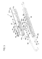
- sliding devices for a vehicle in the present embodiment are seat sliding devices 1 for moving a seat 10 relative to the vehicle in the front-rear direction, are manufactured to be generally left-right symmetrical, and are attached to lower parts on both sides of a seat cushion 11 of the seat 10.
- the respective seat sliding devices 1 have lower rails 30 fixed to a floor 20 of the vehicle and upper rails 40 fixed to the seat 10 side and supported to be relatively slidable relative to the lower rails 30 in a rail axis direction.
- lock members 50 for locking relative movements of the lower rails 30 and the upper rails 40 are arranged between the lower rails 3 and the upper rails 40 of the left and right seat sliding devices 1.
- One manipulation lever 60 which protrudes forward from between the seat 10 and the floor 20 is able to release the locks by the lock members 50. Unless described to the contrary, the construction and operation will be described hereafter with respect to the seat sliding device 1 on one side.
- the lower rail 30 has a base portion 31 parallel to the floor 20 of the vehicle, a first side portion 32a on the outside and a first side portion 32b on the inside which extend upward from both ends of the base portion 31 as they are curved, a second side portion 33a on the outside and a second side portion 33b on the inside curved once inward from the upper ends of both of the first side portions 32a, 32b and extending upward again, and a third side portion 34a on the outside and a third side portion 34b on the inside turned inward from the upper ends of both of the second side portions 33a, 33b and extending downward.
- the third side portions 34a, 34b of the lower rail 30 are formed with engaged portions 35 with which an engaging portion 54 of the lock member 50 referred to later is engaged.
- a plurality of cutouts 35a taking a saw-tooth shape and directed downward are provided at regular intervals in the rail axis direction over a length covering the front-rear maximum moving range of the upper rail 40.
- the upper rail 40 has a first hanging portion 41 a on the outside extending downward toward the floor 20 of the vehicle and a first hanging portion 41 b on the inside being shorter in length than the hanging portion 41a, a base plate portion 42b extending horizontally inward from the lower end of the first hanging portion 41b, a second hanging portion 43b extending downward from one end on the inside of the base plate portion 42b, a slope portion 44a on the outside and a slope portion 44b on the inside extending obliquely upward and outward from lower ends of the hanging portion 41 a and the second hanging portion 43b, and a rising portion 45a on the outside and a rising portion 45b on the inside curved once inward from outside one ends of both of the slope portions 44a, 44b and extending upward.
- an attached portion 46 to which an attaching portion 51 of the lock member 50 is attached is formed at a forward portion in the longitudinal direction on the base plate portion 42b of the upper rail 40.
- the attaching portion 51 and the attached portion 46 are formed as pinholes through which an attaching pin 52 is able to pass.
- a mounting-portion piercing opening 47 through which a mounting portion 55 of the lock member 50 passes is formed at a portion behind the attached portion 46 on the base plate portion 42b.
- engaging-portion piercing openings 49 through which the engaging portion 54 of the lock member 50 passes are formed at portions adjacent to the mounting-portion piercing opening 47 on the hanging portion 41 a, the second hanging portion 43b and both of the rising portions 45a, 45b of the upper rail 40.
- the attached portion 46, the mounting-portion piercing opening 47 and the engaging-portion piercing openings 49 have a function of preventing the lock member 50 from being unlocked or broken when a frontal collision encountered with the lock member 50 held in the lock state causes a large load in the vehicle forward direction inputted to the upper rail 40, and details of these will be referred to later.
- a lever support portion 48 which takes a square shape in section for supporting the manipulation lever 60 is provided upright between the attached portion 46 and the mounting-portion piercing opening 47 on the base plate portion 42b.
- the lever support portion 48 is formed by providing two parallel L-letter shape notches from a mid part on the first hanging portion 41 b to an inside one end of the base plate portion 42b and by turning inward an inland part between the notches to make an inverted L-letter shape.
- a slit 48b of an inverted U-letter shape is formed on the outside vertical wall portion 48a (hanging portion 41a) forming the lever support portion 48.
- a tongue piece portion 48c on an inland side defined by the slit 48b is slightly bent inward, and a one-end side of a lever spring 62 referred to later is made to pass through a clearance defined between the tongue piece portion 48c and the vertical wall portion 48a.
- a vertical wall portion 48d on the inside forming the lever support portion 48 is formed with a cutout 48e on the front part thereof. One end of the lever spring 62 is securely engaged with the cutout 48e.
- the rising portions 45a, 45b of the upper rail 40 are inserted from the front side between the first side portions 32a, 32b, the second side portions 33a, 33b and the third side portions 34a, 34b of the lower rail 30.
- ball bearings 2 are attached to be put between the inner sides of respective curved portions 32aa, 32ab, 32ba, 32bb formed at upper and lower ends of the first side portions 32a, 32b of the lower rail 30 and the outer sides of the slope portions 44a, 44b and the outer sides of curved portions 45aa, 45ba formed at lower ends of the rising portions 45a, 45b.
- the construction is such that the upper rail 40 is supported on the lower rail 30 through the rolling of balls 2a of the ball bearings 2 and is movable smoothly in the front-rear direction.
- the upper rail 40 is supported on the lower rail 30 without having any looseness in both of the vertical and left-right directions in such a manner that in the left-right direction, the slop portions 44a, 44b of the upper rail 40 and the curved portions 45aa, 45ba formed at the lower ends of the rising portions 45a, 45b are put between the pairs of ball bearings 2 located at both of the outer sides and that in the vertical direction, the slope portions 44a, 44b and the curved portions 45aa, 45ba formed at the lower ends of the rising portions 45a, 45b are put between the balls 2a retained in holders 2b of the respective ball beatings 2.
- the lock member 50 is made of an elastic material such as spring steel plate or the like and has the attaching portion 51, a body portion 53, the engaging portion 54, and the mounting portion 55 which are formed bodily.
- the lock member 50 is formed to be receivable in a section area of an inverted U-letter shape which is defined by the hanging portion 41a, the first hanging portion 41 b and the base plate portion 42b of the upper rail 40.
- the body portion 53 is formed to take an almost rectangular plate shape that is narrower in width than the inner width of the base plate portion 42b of the upper rail 40 and that extends in length from the attached portion 46 to the mounting-portion piercing opening 47 in the rail axis direction.
- the attached portion 51 is a round pinhole for the attaching pin 52 to be pierceable through and is formed on a forward end side of the body portion 53.
- the engaging portion 54 takes an almost rectangular plate shape that is wider in width than the outside width of the base plate portion 42b of the upper rail 40 and that is shorter in length than the horizontal width of the engaging-portion piercing openings 49 of the upper rail 40, that is, a shape that protrudes from the engaging-portion piercing openings 49 without contacting the edges of the engaging-portion piercing openings 49 and is provided on an end side behind the body portion 51.
- a plurality (two in the embodiment) of elongate holes 54a which are engageable with the cutouts 35a of the engaged portion 35 of the lower rail 30 are provided at the same interval as the cutouts 35a in the rail axis direction.
- the mounting portion 55 extends upward on the end side behind the engaging portion 54 to have the same width as the body portion 53 and takes an almost rectangular plate shape that protrudes from the mounting-portion piercing opening 47 to almost the same height as the lever support portion 48 without contacting the edge of the mounting-portion piercing opening 47.
- the mounting portion 55 is formed with a vertically oriented elongate hole 55a for an oblong-section portion 61 of the manipulation lever 60 to be inserted and fixed therein. Further, a cutout 55b in which the lever spring 62 is fitted is formed at an outer side of the mounting portion 55.
- the lock member 50 of the construction like this is arranged beneath the base plate portion 42b of the upper rail 40, wherein the engaging portion 54 passes through the engaging-portion piercing openings 49 and wherein the mounting portion 55 passes through the mounting-portion piercing opening 47. Then, the attaching pin 52 is made to pass through the attaching portion 51 of the lock member 50 and the attached portion 46 of the upper rail 40 and is calked, so that the lock member 50 is fixedly attached to the lower surface of the base plate portion 42b of the upper rail 40.
- the lock member 50 made of the elastic material is formed to such a shape that it lifts up the engaging portion 54 about the attaching portion 51 as fulcrum by means of its elastic return force.
- a bending of a Z-shape is made between the engaging portion 54 and the body portion 53 so that the engaging portion 54 of the lock member 50 is placed in parallel to the body portion 53 below the body portion 53.
- the manipulation lever 60 is made of a pipe material to take an almost U-letter shape, and each rear end of both side portions extending rearward is formed by being squashed to an oblong-section portion 61 which is longer in the vertical direction for a higher rigidity against a bending in the vertical direction.
- a notch portion 62 is provided on an upper surface at the vicinity to the rear end of each oblong-section portion 61.
- the manipulation lever 60 is attached to lever support portion 48 of the upper rail 40 and the mounting portion 55 of the lock member 50 by using the lever spring 62.
- the lever spring 62 is made by bending a wire rod, wherein a front portion is once bent outward and has a front end bent to an almost U-letter shape, while a rear portion is once bent upward and has a rear end bent to an almost U-letter shape.
- the U-letter shape portion at the rear end of the lever spring 62 is once disengaged from the cutout 55b on the mounting portion 55 of the lock member 50 and is lifted up, in which state the rear end portion of the oblong-section portion 61 is inserted into the elongate hole 55a at the mounting portion 55 of the lock member 50 to be let go under the rear end of the lever spring 62. Then, the U-letter shape portion at the rear end of the lever spring 62 is securely engaged with the cutout 55b on the mounting portion 55 of the lock member 50 and the notch portion 62 of the oblong-section portion 61.
- the attached portion 46 is formed to a shape that has an attaching hole 46a being somewhat larger in diameter than the outer diameter of the attaching pin 52 and a small hole 46b (corresponding to "movement permitting portion” in the present invention) of a small diameter which is juxtaposed to communicate with a rearward center portion of the attaching hole 46a through a communication portion 46c (corresponding to "movement permitting portion” in the present invention).
- the small hole 46b and the communication portion 46c enable the lock member 50 and the upper rail 40 to move relatively in the rail direction when a frontal collision encountered with the lock member 50 held in the lock state causes a large load to be inputted to the upper rail 40 in the vehicle forward direction.
- engaging-portion piercing opening 49 is formed to an almost rectangular having a width which is wider than the length of the engaging portion 54 in the rail axis direction so that at the time of an insertion, the engaging portion 54 of the lock member 50 does not contact the opening edge portion of the opening 49.
- an oblique portion 49a (corresponding to "movement restraining portion” in the present invention) is formed at a lower part on a rearward side portion of the engaging-portion piercing opening 49.
- the oblique portion 49a is formed so that at the time of relative movement of the lock member 50 and the upper rail 40, it can contact a rear part of the engaging portion 54 of the lock member 50 and can lift up the contacted engaging portion 54 rearward and obliquely above. As described later in detail, it becomes possible for the oblique portion 49a to restrain the lock member 50 from moving in a lock release direction after the relative movement at the aforementioned movement permitting portion.
- the mounting-portion piercing opening 47 is formed to an almost rectangular shape that has a wider width than the length of the mounting portion 55 in a direction orthogonal to the rail axis direction so that when inserted, the mounting portion 55 of the lock member 50 does not contact the opening edge portion of the opening 47.
- narrowing portions 47a, 47b corresponding "movement restraining portion” in the present invention
- the seat sliding device 1 When the seat sliding device 1 having been assembled to the seat 10 is in the lock state, the engaging portion 54 of the lock member 50 is in engagement with the engaged portions 35 of the lower rail 30 thanks to the elastic return force of the lock member 50.
- the passenger manipulates the front end portion of the manipulation lever 60 to raise the front end portion against the elastic return force of the lock member 50, the manipulation lever 60 is pivotally moved about the lever support portion 48 on the upper rail 40 clockwise as viewed in Figure 2 , and at the same time, the rear end portion of the oblong-section portion 61 of the manipulation lever 60 presses on the lower end portion in the elongate hole 55a of the mounting portion 55 of the lock member 50.
- the lock member 50 is pivotally moved about the attached portion 46 of the upper rail 40 clockwise as viewed in Figure 2 , and the engaging portion 54 of the lock member 50 is released from the engaged portions 35 of the lower rail 30 to turn to the lock release state. Therefore, the passenger can move the seat 10 to a desired front-rear position. Then, when the passenger releases the manipulation lever 60 from his hand, the manipulation lever 60 returns to the original position thanks to the elastic return force of the lock member 50, and the engaging member 54 of the lock member 50 is engaged with the engaged portions 35 of the lower rail 30 to turn to the lock state.
- the upper rail 40 applies the forward load as shown in Figure 5(A) to the attaching pin 52 that passes through the attaching hole 46a at the attached portion 46 of the upper rail 40.
- the attaching pin 52 receiving the aforementioned load deforms the communication portion 46c and the small hole 46b at the attached portion 46 and enters the deformed portion, whereby the upper rail 40 moves forward.
- the lock member 50 since the lock member 50 has been secured with the engaging portion 54 being in engagement with the engaged portions 35 of the lower rail 30, the upper rail 40 relatively moves forward relative to the lock member 50.
- the communication portion 46c and the small hole 46b at the attached portion 46 are set to complete their deformations by the force of the half or so of an estimated strength of the lock member 50.
- the attached portion 46 operates in the same manner as the operation having been described with reference to Figure 5 . Then, with the relative movement of the upper rail 40 relative to the lock member 50, the mounting-portion piercing opening 47 of the upper rail 40 through which the mounting portion 55 passes as shown in Figure 7(A) moves forward and moves as the narrowing portions 47a, 47b of the mounting-portion piercing opening 47 are cut in contact with the both side portions of the mounting portion 55, as shown in Figure 7(B) .
- the elongate holes 54a of the engaging portion 54 of the lock member 50 are held engaged to reach the roots of the cutouts 35a of the engaged portions 35 of the lower rail 30, in which the breakage mode in the aforementioned load becomes pure shear, so that a stable lock strength can be ensured.
- the movement permitting portion is formed at the attached portion 46 of the upper rail 40.
- the movement permitting portion may not be formed at the attached portion 46, and instead, a movement permitting portion may be formed on the body portion 53 of the lock member 50, as shown in Figure 8 .
- a curved portion 56 (corresponding to "movement permitting portion" in the present invention) is formed by downwardly bending a portion between the attaching portion 51 and the engaging portion 54 of the lock member 50 in the form of an arc.
- the operation will be performed as described hereafter when a frontal collision encountered causes a large load in the vehicle forward direction to be inputted to the upper rail 40.
- the upper rail 40 experts a forward load on the attaching pin 52 which is inserted in the attached portion 46 of the upper rail 40.
- the elongate holes 54a of the engaging portion 54 of the lock member 50 are held engaged to reach the roots of the cutouts 35a of the engaged portions 35 of the lower rail 30, in which the breakage mode in the aforementioned load becomes pure shear, so that a stable lock strength can be ensured.
- Figures 10(A) through (C) show modified forms of the movement permitting portion formed at the attached portion 46 of the upper rail 40.
- the attached portion 46 is formed to a shape that has an attaching hole 46a being slightly larger than the outer diameter of the attaching pin 52, an escape hole 46d (corresponding to "movement permitting portion” in the present invention) juxtaposed with a space from the attaching hole 46a and being the same as the attaching hole 46a in diameter, and a communication portion 46e (corresponding to "movement permitting portion” in the present invention) making the attaching hole 46a and the escape hole 46d communicate with each other.
- the communication portion 46e at the attached portion 46 is deformed to permit the attaching pin 52 to enter the escape hole 46d through the deformed portion, whereby it results that the upper rail 40 is relatively moved forward relative to the lock member 50. It is to be noted that the communication portion 46e of the attached portion 46 is set to complete its deformation by the force of the half or so of the estimated strength of the lock member 50.
- the attached portion 46 is formed to a shape that has an attaching hole 46a being slightly larger in diameter than the outer diameter of the attaching pin 52, an elongate hole 46f (corresponding to "movement permitting portion” in the present invention) provided to extend rearward from a rear center portion of the attaching hole 46a, and two elliptical holes 46g (corresponding to "movement permitting portion” in the present invention) provided on upper and lower sides of the elongate hole 46f.
- the elongate hole 46f at the attached portion 46 is deformed toward the two elliptical holes 46g sides and permits the attaching pin 52 to enter the deformed portion, whereby it results that the upper rail 40 is relatively moved forward relative to the lock member 50. It is to be noted that the elongate hole 46f at the attached portion 46 is set to complete its deformation by the force of the half or so of the estimated strength of the lock member 50.
- the attached portion 46 is formed to a shape that has an attaching hole 46a being slightly larger in diameter than the outer diameter of the attaching pin 52, an elongate hole 46h (corresponding to "movement permitting portion” in the present invention) provided to extend rearward from a rear lower-side portion of the attaching hole 46a, and an elliptical hole 46i (corresponding to "movement permitting portion” in the present invention) provided on an upper side of the elongate hole 46h.
- the elongate hole 46h at the attached portion 46 is deformed toward the elliptical hole 46i side and permits the attaching pin 52 to enter the deformed portion, whereby it results that the upper rail 40 relatively moves forward relative to the lock member 50. It is to be noted that the elongate hole 46h at the attached portion 46 is set to complete its deformation by the force of the half or so of the estimated strength of the lock member 50.
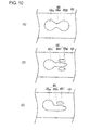
- FIG 11 is a view showing a modified form of the mounting portion 55 of the lock member 50.
- the mounting portion 55 is formed with the aforementioned elongate hole 55a and the cutout 55b, and further, a lower part of the mounting portion 55 is formed at both side portions thereof with cutouts 55c, 55d which enable the narrowing portions 47a, 47b of the mounting-portion piercing opening 47 shown in Figure 7(A) to come thereinto.
- the narrowing portions 47a, 47b of the mounting-portion piercing opening 47 move as they come into the cutouts 55c, 55d of the mounting portion 55.
- the narrowing portions 47a, 47b of the mounting-portion piercing opening 47 may move while held in contact with and thus cut by the both side portions of the mounting portion 55.
- Figure 12(A) is a view showing a modified form of the movement restraining portion formed at the mounting-portion piercing opening 47 of the upper rail 40 and is the view showing the movement restraining portion which is adapted to the mounting portion 55 formed with the cutouts 55c, 55d shown in Figure 11 .
- the mounting-portion piercing opening 47 has a large rectangular shape portion 47c that has a wider width than the width of the mounting portion 55 in the direction orthogonal to the rail axis direction so that the mounting portion 55 of the lock member 50 does not contact the opening edge portion, and a small rectangular shape portion 47d that is formed to communicate with a rear center of the large rectangular shape portion 47c and that has a slightly wider width than the distance between the cutouts 55c, 55d of the mounting portion 55.
- stepped portions 47e, 47f (corresponding to "movement restraining portion” in the present invention) which narrow the width of the mounting-portion piercing opening 47 so as to be able to come into the cutouts 55c, 55d of the mounting portion 55 at the time of relative movement between the lock member 50 and the upper rail 40.
- the lock member 50 is restrained from moving in the lock release direction and can further stably maintain the state that the relative movement between the lower rail 30 and the upper rail 40 has been locked against an inputted large load in the vehicle forward direction. Further, the elongate holes 54a at the engaging portion 54 of the lock member 50 are held engaged to reach the roots of the cutouts 35a of the engaged portions 35 of the lower rail 30, in which the breakage mode in the aforementioned load becomes pure shear, so that a stable lock strength can be ensured.
- the movement permitting portion is formed at the attached portion 46 of the upper rail 40
- a movement permitting portion of the same shape may be formed at the attaching portion 51 of the lock member 50.
- the movement permitting portion at the attaching portion 51 is formed on the forward side of the attaching hole 46a with the attaching pin 52 passing therethrough.
- the movement permitting portion at the attached portion 46 and the movement permitting portion at the attaching portion 51 either one of them may be formed or both of them may be formed.
- the present invention is applied to the sliding device 1 for the vehicle of the type that the lock member 50 moves vertically relative to the rail axis to perform the lock and the lock release
- the present invention may also be applicable to a sliding device for a vehicle of the type that the lock member turns about the rail axis to perform the lock and the lock release.
- the sliding device may be applicable to one for a vehicle that is required to slice.
- the sliding device for the vehicle according to the present invention is suitable for use in a sliding device for a vehicle that is provided with a pair or first rails fixed to a vehicle and a pair of second rails supported slidably relative to the first rails and that supports a seat of a vehicle movably in a front-rear direction.
- 1...siding device for vehicle 30...lower rail, 35...engaged portion, 40...upper rail, 46...attached portion, 46b...small hole (movement permitting portion), 46c...communication portion (movement permitting portion), 46d...escape hole (movement permitting portion), 46e... communication portion (movement permitting portion), 46f...elongate hole (movement permitting portion), 46g...elliptical hole (movement permitting portion), 46h...elongate hole (movement permitting portion), 46i...
Landscapes
- Engineering & Computer Science (AREA)
- Aviation & Aerospace Engineering (AREA)
- Transportation (AREA)
- Mechanical Engineering (AREA)
- Seats For Vehicles (AREA)
Applications Claiming Priority (2)
| Application Number | Priority Date | Filing Date | Title |
|---|---|---|---|
| JP2009253532A JP4947123B2 (ja) | 2009-11-04 | 2009-11-04 | 車両用スライド装置 |
| PCT/JP2010/067961 WO2011055615A1 (fr) | 2009-11-04 | 2010-10-13 | Dispositif coulissant pour véhicule |
Publications (3)
| Publication Number | Publication Date |
|---|---|
| EP2497683A1 true EP2497683A1 (fr) | 2012-09-12 |
| EP2497683A4 EP2497683A4 (fr) | 2012-10-03 |
| EP2497683B1 EP2497683B1 (fr) | 2013-11-20 |
Family
ID=43969855
Family Applications (1)
| Application Number | Title | Priority Date | Filing Date |
|---|---|---|---|
| EP10828175.9A Not-in-force EP2497683B1 (fr) | 2009-11-04 | 2010-10-13 | Dispositif coulissant pour véhicule |
Country Status (6)
| Country | Link |
|---|---|
| US (1) | US8708300B2 (fr) |
| EP (1) | EP2497683B1 (fr) |
| JP (1) | JP4947123B2 (fr) |
| CN (1) | CN202641425U (fr) |
| BR (1) | BR112012011456A2 (fr) |
| WO (1) | WO2011055615A1 (fr) |
Cited By (1)
| Publication number | Priority date | Publication date | Assignee | Title |
|---|---|---|---|---|
| EP2631110A1 (fr) * | 2012-02-21 | 2013-08-28 | Aisin Seiki Kabushiki Kaisha | Appareil coulissant de siège pour véhicule |
Families Citing this family (36)
| Publication number | Priority date | Publication date | Assignee | Title |
|---|---|---|---|---|
| JP2012126181A (ja) * | 2010-12-13 | 2012-07-05 | Shiroki Corp | スライドレール装置 |
| JP5647507B2 (ja) * | 2010-12-13 | 2014-12-24 | シロキ工業株式会社 | 車両用スライドレール装置 |
| JP5691542B2 (ja) * | 2011-01-18 | 2015-04-01 | トヨタ紡織株式会社 | 乗物シート用スライド装置 |
| JP5659974B2 (ja) * | 2011-07-12 | 2015-01-28 | アイシン精機株式会社 | 車両用シートスライド装置 |
| DE102011115948B3 (de) * | 2011-10-12 | 2013-01-24 | Keiper Gmbh & Co. Kg | Längseinstellbarer Fahrzeugsitz |
| JP6108783B2 (ja) * | 2012-01-24 | 2017-04-05 | シロキ工業株式会社 | パワーシートスライド装置 |
| JP5734890B2 (ja) * | 2012-02-15 | 2015-06-17 | シロキ工業株式会社 | 車両用スライドレール装置 |
| WO2014024779A1 (fr) * | 2012-08-09 | 2014-02-13 | アイシン精機 株式会社 | Dispositif de glissière de siège pour véhicule |
| JP2014034330A (ja) * | 2012-08-09 | 2014-02-24 | Aisin Seiki Co Ltd | 車両用シートスライド装置 |
| JP5998856B2 (ja) * | 2012-11-01 | 2016-09-28 | アイシン精機株式会社 | 車両用シートスライド装置 |
| US9038981B2 (en) * | 2012-10-19 | 2015-05-26 | Aisin Seiki Kabushiki Kaisha | Seat apparatus for vehicle |
| JP5974816B2 (ja) * | 2012-10-19 | 2016-08-23 | アイシン精機株式会社 | 車両用シートスライド装置 |
| JP5983295B2 (ja) * | 2012-10-19 | 2016-08-31 | アイシン精機株式会社 | 車両用シートスライド装置 |
| JP5974815B2 (ja) * | 2012-10-19 | 2016-08-23 | アイシン精機株式会社 | 車両用シートスライド装置 |
| JP5613744B2 (ja) * | 2012-10-24 | 2014-10-29 | シロキ工業株式会社 | 車両用スライドレール装置 |
| JP6028614B2 (ja) * | 2013-02-19 | 2016-11-16 | アイシン精機株式会社 | 車両用シートスライド装置 |
| JP6320187B2 (ja) * | 2014-06-16 | 2018-05-09 | シロキ工業株式会社 | 車両用シートスライド装置の組立装置及び組立方法 |
| DE102014211993B4 (de) * | 2014-06-23 | 2019-09-05 | Lear Corporation | Sitzschienenanordnung mit Lastaufnahmestrukturen und Fahrzeugsitzanordnung |
| JP6456253B2 (ja) * | 2014-08-11 | 2019-01-23 | 株式会社Tf−Metal | シートスライド装置 |
| DE102014225426B4 (de) * | 2014-10-20 | 2022-01-13 | Adient Luxembourg Holding S.À R.L. | Längseinsteller für einen Fahrzeugsitz und Fahrzeugsitz |
| US10933772B2 (en) | 2014-12-12 | 2021-03-02 | Adient Luxembourg Holding S.Á R.L. | Longitudinal adjuster for a vehicle seat, and vehicle seat |
| US10160350B2 (en) * | 2015-06-30 | 2018-12-25 | Brose Fahrzeugteile Gmbh & Co. Kg, Coburg | Adjusting device for longitudinal adjustment of a vehicle seat and method for assembly |
| JP6488939B2 (ja) | 2015-08-06 | 2019-03-27 | アイシン精機株式会社 | 車両用シートスライド装置 |
| DE102017208725A1 (de) * | 2016-05-26 | 2017-11-30 | Toyota Boshoku Kabushiki Kaisha | Sitzlängsverstellvorrichtung |
| DE102016225818B4 (de) * | 2016-09-21 | 2021-05-12 | Adient Luxembourg Holding S.À R.L. | Längseinsteller sowie Fahrzeugsitz |
| DE102016218236B4 (de) * | 2016-09-22 | 2022-05-05 | Lear Corporation | Sitzschienen-Anordnung |
| US10940775B2 (en) | 2018-03-16 | 2021-03-09 | Tf-Metal Co., Ltd. | Seat slide device |
| JP7023148B2 (ja) * | 2018-03-16 | 2022-02-21 | 株式会社Tf-Metal | シートスライド装置 |
| IT201800005731A1 (it) | 2018-05-25 | 2019-11-25 | Dispositivo di scorrimento per un sedile di veicolo | |
| IT201800006570A1 (it) * | 2018-06-21 | 2019-12-21 | Dispositivo di scorrimento per un sedile di veicolo provvisto di un sistema di bloccaggio migliorato | |
| IT201800006569A1 (it) * | 2018-06-21 | 2019-12-21 | Dispositivo di scorrimento per un sedile di veicolo provvisto di un sistema di bloccaggio migliorato | |
| JP7186102B2 (ja) | 2019-01-25 | 2022-12-08 | トヨタ紡織株式会社 | スライド装置 |
| JP7173885B2 (ja) * | 2019-01-25 | 2022-11-16 | トヨタ紡織株式会社 | スライド装置 |
| JP7173884B2 (ja) * | 2019-01-25 | 2022-11-16 | トヨタ紡織株式会社 | スライド装置 |
| JP7388259B2 (ja) * | 2020-03-13 | 2023-11-29 | トヨタ紡織株式会社 | 解除ハンドル |
| DE102021122623A1 (de) | 2021-06-18 | 2022-12-22 | Adient Us Llc | Verfahren zur herstellung eines betätigungshebels für einen längseinsteller, sowie betätigungshebel, längseinsteller und fahrzeugsitz |
Citations (3)
| Publication number | Priority date | Publication date | Assignee | Title |
|---|---|---|---|---|
| FR2767096A1 (fr) * | 1997-08-05 | 1999-02-12 | Faure Bertrand Equipements Sa | Glissiere pour siege de vehicules automobiles, comportant un verrou constitue d'une lame elastiquement flexible |
| DE10046204A1 (de) * | 2000-09-19 | 2002-06-06 | Keiper Gmbh & Co | Fahrzeugsitz-Längseinstellvorrichtung mit Zusatzverriegelung |
| DE202007004524U1 (de) * | 2007-03-28 | 2008-08-07 | Brose Fahrzeugteile Gmbh & Co. Kommanditgesellschaft, Coburg | Arretiervorrichtung für einen Kraftfahrzeugsitz |
Family Cites Families (12)
| Publication number | Priority date | Publication date | Assignee | Title |
|---|---|---|---|---|
| JPS5958638A (ja) * | 1982-09-28 | 1984-04-04 | Nec Corp | 光学的記録再生用光ヘツド |
| JPS5958638U (ja) * | 1982-10-13 | 1984-04-17 | 市光工業株式会社 | シ−トアジヤスタ |
| JP3646327B2 (ja) * | 1994-11-11 | 2005-05-11 | アイシン精機株式会社 | 車両用シートスライド装置 |
| JP2000085421A (ja) * | 1998-09-16 | 2000-03-28 | Toyo Seat Co Ltd | 車両用シートのスライド装置 |
| JP4121862B2 (ja) * | 2003-01-24 | 2008-07-23 | 岐阜車体工業株式会社 | 車両用シートトラックスライド装置におけるロック機構 |
| JP2008074380A (ja) * | 2006-08-25 | 2008-04-03 | Aisin Seiki Co Ltd | 車両用シートスライド装置 |
| JP4355963B2 (ja) | 2007-01-30 | 2009-11-04 | 株式会社今仙電機製作所 | スライドレール装置 |
| JP2009241919A (ja) * | 2007-11-15 | 2009-10-22 | Imasen Electric Ind Co Ltd | シートスライド装置 |
| DE102008034788B4 (de) * | 2008-02-28 | 2012-06-14 | Lear Corporation | Sitzanordnung und Längs-Sitzverstellvorrichtung für einen Fahrzeugsitz |
| US20120001049A1 (en) * | 2008-04-18 | 2012-01-05 | Johnson Controls Technology Company | Latch mechanism |
| JP5309802B2 (ja) * | 2008-09-02 | 2013-10-09 | アイシン精機株式会社 | 車両用シートスライド装置 |
| JP5214711B2 (ja) * | 2010-11-25 | 2013-06-19 | 岐阜車体工業株式会社 | シートトラックスライド装置におけるロック機構 |
-
2009
- 2009-11-04 JP JP2009253532A patent/JP4947123B2/ja not_active Expired - Fee Related
-
2010
- 2010-10-13 CN CN2010900011374U patent/CN202641425U/zh not_active Expired - Fee Related
- 2010-10-13 US US13/503,527 patent/US8708300B2/en not_active Expired - Fee Related
- 2010-10-13 BR BR112012011456-5A patent/BR112012011456A2/pt not_active Application Discontinuation
- 2010-10-13 EP EP10828175.9A patent/EP2497683B1/fr not_active Not-in-force
- 2010-10-13 WO PCT/JP2010/067961 patent/WO2011055615A1/fr active Application Filing
Patent Citations (3)
| Publication number | Priority date | Publication date | Assignee | Title |
|---|---|---|---|---|
| FR2767096A1 (fr) * | 1997-08-05 | 1999-02-12 | Faure Bertrand Equipements Sa | Glissiere pour siege de vehicules automobiles, comportant un verrou constitue d'une lame elastiquement flexible |
| DE10046204A1 (de) * | 2000-09-19 | 2002-06-06 | Keiper Gmbh & Co | Fahrzeugsitz-Längseinstellvorrichtung mit Zusatzverriegelung |
| DE202007004524U1 (de) * | 2007-03-28 | 2008-08-07 | Brose Fahrzeugteile Gmbh & Co. Kommanditgesellschaft, Coburg | Arretiervorrichtung für einen Kraftfahrzeugsitz |
Non-Patent Citations (1)
| Title |
|---|
| See also references of WO2011055615A1 * |
Cited By (1)
| Publication number | Priority date | Publication date | Assignee | Title |
|---|---|---|---|---|
| EP2631110A1 (fr) * | 2012-02-21 | 2013-08-28 | Aisin Seiki Kabushiki Kaisha | Appareil coulissant de siège pour véhicule |
Also Published As
| Publication number | Publication date |
|---|---|
| EP2497683B1 (fr) | 2013-11-20 |
| JP4947123B2 (ja) | 2012-06-06 |
| CN202641425U (zh) | 2013-01-02 |
| BR112012011456A2 (pt) | 2020-12-08 |
| US8708300B2 (en) | 2014-04-29 |
| US20120205512A1 (en) | 2012-08-16 |
| JP2011098610A (ja) | 2011-05-19 |
| EP2497683A4 (fr) | 2012-10-03 |
| WO2011055615A1 (fr) | 2011-05-12 |
Similar Documents
| Publication | Publication Date | Title |
|---|---|---|
| EP2497683B1 (fr) | Dispositif coulissant pour véhicule | |
| US8360383B2 (en) | Seat sliding device | |
| KR100610431B1 (ko) | 자동차용 시트 슬라이드 장치 | |
| US4068887A (en) | Seat mountings | |
| US6953178B2 (en) | Seat slide device for vehicle | |
| US9038981B2 (en) | Seat apparatus for vehicle | |
| EP2415629B1 (fr) | Appareil coulissant de siège pour véhicule | |
| WO2002066285A1 (fr) | Siege de voiture | |
| CN109715438B (zh) | 导轨及车辆座椅 | |
| EP1757484A3 (fr) | Siège d'enfant pour automobile | |
| US20150217661A1 (en) | Slide rail | |
| EP2213506A2 (fr) | Appareil coulissant de siège pour véhicule | |
| CN109476242B (zh) | 纵向调节器和车辆座椅 | |
| US6431632B1 (en) | Automobile seat assembly attachment structure | |
| JP5431076B2 (ja) | 車両用シートのスライド構造 | |
| CN106994922B (zh) | 儿童座椅 | |
| EP1046541A1 (fr) | Mécanisme de réglage d'un appui-tête d'un siège de véhicule | |
| US7195311B2 (en) | Safety device for vehicle seats | |
| CN110303957B (zh) | 纵向调节器及车辆座椅 | |
| JP5082490B2 (ja) | 車両用シート | |
| CN108928269B (zh) | 儿童座椅 | |
| KR101995345B1 (ko) | 헤드레스트 틸팅장치 | |
| JP5093006B2 (ja) | クリップ付き車両部品構成体 | |
| JP2012131467A (ja) | シートスライド装置 | |
| JP2012101561A (ja) | 車両用シート |
Legal Events
| Date | Code | Title | Description |
|---|---|---|---|
| PUAI | Public reference made under article 153(3) epc to a published international application that has entered the european phase |
Free format text: ORIGINAL CODE: 0009012 |
|
| 17P | Request for examination filed |
Effective date: 20120416 |
|
| AK | Designated contracting states |
Kind code of ref document: A1 Designated state(s): AL AT BE BG CH CY CZ DE DK EE ES FI FR GB GR HR HU IE IS IT LI LT LU LV MC MK MT NL NO PL PT RO RS SE SI SK SM TR |
|
| A4 | Supplementary search report drawn up and despatched |
Effective date: 20120903 |
|
| RIC1 | Information provided on ipc code assigned before grant |
Ipc: B60N 2/08 20060101AFI20120828BHEP Ipc: B60N 2/42 20060101ALI20120828BHEP Ipc: B60N 2/433 20060101ALI20120828BHEP |
|
| DAX | Request for extension of the european patent (deleted) | ||
| GRAP | Despatch of communication of intention to grant a patent |
Free format text: ORIGINAL CODE: EPIDOSNIGR1 |
|
| INTG | Intention to grant announced |
Effective date: 20130611 |
|
| GRAS | Grant fee paid |
Free format text: ORIGINAL CODE: EPIDOSNIGR3 |
|
| GRAA | (expected) grant |
Free format text: ORIGINAL CODE: 0009210 |
|
| AK | Designated contracting states |
Kind code of ref document: B1 Designated state(s): AL AT BE BG CH CY CZ DE DK EE ES FI FR GB GR HR HU IE IS IT LI LT LU LV MC MK MT NL NO PL PT RO RS SE SI SK SM TR |
|
| REG | Reference to a national code |
Ref country code: GB Ref legal event code: FG4D |
|
| REG | Reference to a national code |
Ref country code: CH Ref legal event code: EP |
|
| REG | Reference to a national code |
Ref country code: AT Ref legal event code: REF Ref document number: 641376 Country of ref document: AT Kind code of ref document: T Effective date: 20131215 |
|
| REG | Reference to a national code |
Ref country code: IE Ref legal event code: FG4D |
|
| REG | Reference to a national code |
Ref country code: DE Ref legal event code: R096 Ref document number: 602010011988 Country of ref document: DE Effective date: 20140116 |
|
| REG | Reference to a national code |
Ref country code: NL Ref legal event code: VDEP Effective date: 20131120 |
|
| REG | Reference to a national code |
Ref country code: AT Ref legal event code: MK05 Ref document number: 641376 Country of ref document: AT Kind code of ref document: T Effective date: 20131120 |
|
| REG | Reference to a national code |
Ref country code: LT Ref legal event code: MG4D |
|
| PG25 | Lapsed in a contracting state [announced via postgrant information from national office to epo] |
Ref country code: LT Free format text: LAPSE BECAUSE OF FAILURE TO SUBMIT A TRANSLATION OF THE DESCRIPTION OR TO PAY THE FEE WITHIN THE PRESCRIBED TIME-LIMIT Effective date: 20131120 Ref country code: IS Free format text: LAPSE BECAUSE OF FAILURE TO SUBMIT A TRANSLATION OF THE DESCRIPTION OR TO PAY THE FEE WITHIN THE PRESCRIBED TIME-LIMIT Effective date: 20140320 Ref country code: FI Free format text: LAPSE BECAUSE OF FAILURE TO SUBMIT A TRANSLATION OF THE DESCRIPTION OR TO PAY THE FEE WITHIN THE PRESCRIBED TIME-LIMIT Effective date: 20131120 Ref country code: NO Free format text: LAPSE BECAUSE OF FAILURE TO SUBMIT A TRANSLATION OF THE DESCRIPTION OR TO PAY THE FEE WITHIN THE PRESCRIBED TIME-LIMIT Effective date: 20140220 Ref country code: SE Free format text: LAPSE BECAUSE OF FAILURE TO SUBMIT A TRANSLATION OF THE DESCRIPTION OR TO PAY THE FEE WITHIN THE PRESCRIBED TIME-LIMIT Effective date: 20131120 Ref country code: NL Free format text: LAPSE BECAUSE OF FAILURE TO SUBMIT A TRANSLATION OF THE DESCRIPTION OR TO PAY THE FEE WITHIN THE PRESCRIBED TIME-LIMIT Effective date: 20131120 Ref country code: HR Free format text: LAPSE BECAUSE OF FAILURE TO SUBMIT A TRANSLATION OF THE DESCRIPTION OR TO PAY THE FEE WITHIN THE PRESCRIBED TIME-LIMIT Effective date: 20131120 |
|
| PG25 | Lapsed in a contracting state [announced via postgrant information from national office to epo] |
Ref country code: LV Free format text: LAPSE BECAUSE OF FAILURE TO SUBMIT A TRANSLATION OF THE DESCRIPTION OR TO PAY THE FEE WITHIN THE PRESCRIBED TIME-LIMIT Effective date: 20131120 Ref country code: RS Free format text: LAPSE BECAUSE OF FAILURE TO SUBMIT A TRANSLATION OF THE DESCRIPTION OR TO PAY THE FEE WITHIN THE PRESCRIBED TIME-LIMIT Effective date: 20131120 Ref country code: AT Free format text: LAPSE BECAUSE OF FAILURE TO SUBMIT A TRANSLATION OF THE DESCRIPTION OR TO PAY THE FEE WITHIN THE PRESCRIBED TIME-LIMIT Effective date: 20131120 Ref country code: BE Free format text: LAPSE BECAUSE OF FAILURE TO SUBMIT A TRANSLATION OF THE DESCRIPTION OR TO PAY THE FEE WITHIN THE PRESCRIBED TIME-LIMIT Effective date: 20131120 Ref country code: ES Free format text: LAPSE BECAUSE OF FAILURE TO SUBMIT A TRANSLATION OF THE DESCRIPTION OR TO PAY THE FEE WITHIN THE PRESCRIBED TIME-LIMIT Effective date: 20131120 |
|
| PG25 | Lapsed in a contracting state [announced via postgrant information from national office to epo] |
Ref country code: PT Free format text: LAPSE BECAUSE OF FAILURE TO SUBMIT A TRANSLATION OF THE DESCRIPTION OR TO PAY THE FEE WITHIN THE PRESCRIBED TIME-LIMIT Effective date: 20140320 |
|
| PG25 | Lapsed in a contracting state [announced via postgrant information from national office to epo] |
Ref country code: EE Free format text: LAPSE BECAUSE OF FAILURE TO SUBMIT A TRANSLATION OF THE DESCRIPTION OR TO PAY THE FEE WITHIN THE PRESCRIBED TIME-LIMIT Effective date: 20131120 |
|
| REG | Reference to a national code |
Ref country code: DE Ref legal event code: R097 Ref document number: 602010011988 Country of ref document: DE |
|
| PG25 | Lapsed in a contracting state [announced via postgrant information from national office to epo] |
Ref country code: RO Free format text: LAPSE BECAUSE OF FAILURE TO SUBMIT A TRANSLATION OF THE DESCRIPTION OR TO PAY THE FEE WITHIN THE PRESCRIBED TIME-LIMIT Effective date: 20131120 Ref country code: PL Free format text: LAPSE BECAUSE OF FAILURE TO SUBMIT A TRANSLATION OF THE DESCRIPTION OR TO PAY THE FEE WITHIN THE PRESCRIBED TIME-LIMIT Effective date: 20131120 Ref country code: CZ Free format text: LAPSE BECAUSE OF FAILURE TO SUBMIT A TRANSLATION OF THE DESCRIPTION OR TO PAY THE FEE WITHIN THE PRESCRIBED TIME-LIMIT Effective date: 20131120 Ref country code: SK Free format text: LAPSE BECAUSE OF FAILURE TO SUBMIT A TRANSLATION OF THE DESCRIPTION OR TO PAY THE FEE WITHIN THE PRESCRIBED TIME-LIMIT Effective date: 20131120 |
|
| PLBE | No opposition filed within time limit |
Free format text: ORIGINAL CODE: 0009261 |
|
| STAA | Information on the status of an ep patent application or granted ep patent |
Free format text: STATUS: NO OPPOSITION FILED WITHIN TIME LIMIT |
|
| PG25 | Lapsed in a contracting state [announced via postgrant information from national office to epo] |
Ref country code: DK Free format text: LAPSE BECAUSE OF FAILURE TO SUBMIT A TRANSLATION OF THE DESCRIPTION OR TO PAY THE FEE WITHIN THE PRESCRIBED TIME-LIMIT Effective date: 20131120 |
|
| 26N | No opposition filed |
Effective date: 20140821 |
|
| REG | Reference to a national code |
Ref country code: DE Ref legal event code: R097 Ref document number: 602010011988 Country of ref document: DE Effective date: 20140821 |
|
| PGFP | Annual fee paid to national office [announced via postgrant information from national office to epo] |
Ref country code: DE Payment date: 20141007 Year of fee payment: 5 Ref country code: FR Payment date: 20141008 Year of fee payment: 5 |
|
| PG25 | Lapsed in a contracting state [announced via postgrant information from national office to epo] |
Ref country code: SI Free format text: LAPSE BECAUSE OF FAILURE TO SUBMIT A TRANSLATION OF THE DESCRIPTION OR TO PAY THE FEE WITHIN THE PRESCRIBED TIME-LIMIT Effective date: 20131120 |
|
| PG25 | Lapsed in a contracting state [announced via postgrant information from national office to epo] |
Ref country code: MC Free format text: LAPSE BECAUSE OF FAILURE TO SUBMIT A TRANSLATION OF THE DESCRIPTION OR TO PAY THE FEE WITHIN THE PRESCRIBED TIME-LIMIT Effective date: 20131120 Ref country code: LU Free format text: LAPSE BECAUSE OF FAILURE TO SUBMIT A TRANSLATION OF THE DESCRIPTION OR TO PAY THE FEE WITHIN THE PRESCRIBED TIME-LIMIT Effective date: 20141013 |
|
| REG | Reference to a national code |
Ref country code: CH Ref legal event code: PL |
|
| GBPC | Gb: european patent ceased through non-payment of renewal fee |
Effective date: 20141013 |
|
| REG | Reference to a national code |
Ref country code: IE Ref legal event code: MM4A |
|
| PG25 | Lapsed in a contracting state [announced via postgrant information from national office to epo] |
Ref country code: LI Free format text: LAPSE BECAUSE OF NON-PAYMENT OF DUE FEES Effective date: 20141031 Ref country code: GB Free format text: LAPSE BECAUSE OF NON-PAYMENT OF DUE FEES Effective date: 20141013 Ref country code: CH Free format text: LAPSE BECAUSE OF NON-PAYMENT OF DUE FEES Effective date: 20141031 |
|
| PG25 | Lapsed in a contracting state [announced via postgrant information from national office to epo] |
Ref country code: IT Free format text: LAPSE BECAUSE OF FAILURE TO SUBMIT A TRANSLATION OF THE DESCRIPTION OR TO PAY THE FEE WITHIN THE PRESCRIBED TIME-LIMIT Effective date: 20131120 |
|
| PG25 | Lapsed in a contracting state [announced via postgrant information from national office to epo] |
Ref country code: IE Free format text: LAPSE BECAUSE OF NON-PAYMENT OF DUE FEES Effective date: 20141013 |
|
| PG25 | Lapsed in a contracting state [announced via postgrant information from national office to epo] |
Ref country code: SM Free format text: LAPSE BECAUSE OF FAILURE TO SUBMIT A TRANSLATION OF THE DESCRIPTION OR TO PAY THE FEE WITHIN THE PRESCRIBED TIME-LIMIT Effective date: 20131120 |
|
| REG | Reference to a national code |
Ref country code: DE Ref legal event code: R119 Ref document number: 602010011988 Country of ref document: DE |
|
| PG25 | Lapsed in a contracting state [announced via postgrant information from national office to epo] |
Ref country code: GR Free format text: LAPSE BECAUSE OF FAILURE TO SUBMIT A TRANSLATION OF THE DESCRIPTION OR TO PAY THE FEE WITHIN THE PRESCRIBED TIME-LIMIT Effective date: 20140221 Ref country code: CY Free format text: LAPSE BECAUSE OF FAILURE TO SUBMIT A TRANSLATION OF THE DESCRIPTION OR TO PAY THE FEE WITHIN THE PRESCRIBED TIME-LIMIT Effective date: 20131120 Ref country code: BG Free format text: LAPSE BECAUSE OF FAILURE TO SUBMIT A TRANSLATION OF THE DESCRIPTION OR TO PAY THE FEE WITHIN THE PRESCRIBED TIME-LIMIT Effective date: 20131120 |
|
| PG25 | Lapsed in a contracting state [announced via postgrant information from national office to epo] |
Ref country code: TR Free format text: LAPSE BECAUSE OF FAILURE TO SUBMIT A TRANSLATION OF THE DESCRIPTION OR TO PAY THE FEE WITHIN THE PRESCRIBED TIME-LIMIT Effective date: 20131120 Ref country code: HU Free format text: LAPSE BECAUSE OF FAILURE TO SUBMIT A TRANSLATION OF THE DESCRIPTION OR TO PAY THE FEE WITHIN THE PRESCRIBED TIME-LIMIT; INVALID AB INITIO Effective date: 20101013 Ref country code: DE Free format text: LAPSE BECAUSE OF NON-PAYMENT OF DUE FEES Effective date: 20160503 Ref country code: MT Free format text: LAPSE BECAUSE OF FAILURE TO SUBMIT A TRANSLATION OF THE DESCRIPTION OR TO PAY THE FEE WITHIN THE PRESCRIBED TIME-LIMIT Effective date: 20131120 |
|
| REG | Reference to a national code |
Ref country code: FR Ref legal event code: ST Effective date: 20160630 |
|
| PG25 | Lapsed in a contracting state [announced via postgrant information from national office to epo] |
Ref country code: FR Free format text: LAPSE BECAUSE OF NON-PAYMENT OF DUE FEES Effective date: 20151102 |
|
| PG25 | Lapsed in a contracting state [announced via postgrant information from national office to epo] |
Ref country code: MK Free format text: LAPSE BECAUSE OF FAILURE TO SUBMIT A TRANSLATION OF THE DESCRIPTION OR TO PAY THE FEE WITHIN THE PRESCRIBED TIME-LIMIT Effective date: 20131120 |
|
| PG25 | Lapsed in a contracting state [announced via postgrant information from national office to epo] |
Ref country code: AL Free format text: LAPSE BECAUSE OF FAILURE TO SUBMIT A TRANSLATION OF THE DESCRIPTION OR TO PAY THE FEE WITHIN THE PRESCRIBED TIME-LIMIT Effective date: 20131120 |