EP2496908B1 - Fliegerbombe - Google Patents
Fliegerbombe Download PDFInfo
- Publication number
- EP2496908B1 EP2496908B1 EP09749015.5A EP09749015A EP2496908B1 EP 2496908 B1 EP2496908 B1 EP 2496908B1 EP 09749015 A EP09749015 A EP 09749015A EP 2496908 B1 EP2496908 B1 EP 2496908B1
- Authority
- EP
- European Patent Office
- Prior art keywords
- bomb
- penetrator
- flying
- casing
- explosive
- Prior art date
- Legal status (The legal status is an assumption and is not a legal conclusion. Google has not performed a legal analysis and makes no representation as to the accuracy of the status listed.)
- Active
Links
- 239000002360 explosive Substances 0.000 claims description 44
- 229910000831 Steel Inorganic materials 0.000 claims description 7
- 239000010959 steel Substances 0.000 claims description 7
- 239000006260 foam Substances 0.000 claims description 5
- 238000009434 installation Methods 0.000 claims description 3
- 230000000694 effects Effects 0.000 description 6
- 230000035515 penetration Effects 0.000 description 6
- 239000003795 chemical substances by application Substances 0.000 description 4
- 125000006850 spacer group Chemical group 0.000 description 4
- 239000000725 suspension Substances 0.000 description 4
- 210000003128 head Anatomy 0.000 description 2
- 230000003111 delayed effect Effects 0.000 description 1
- 238000011161 development Methods 0.000 description 1
- 230000018109 developmental process Effects 0.000 description 1
- 239000000834 fixative Substances 0.000 description 1
- 230000005484 gravity Effects 0.000 description 1
- 230000010354 integration Effects 0.000 description 1
- 230000010534 mechanism of action Effects 0.000 description 1
- 230000000149 penetrating effect Effects 0.000 description 1
- 230000000704 physical effect Effects 0.000 description 1
Images

Classifications
-
- F—MECHANICAL ENGINEERING; LIGHTING; HEATING; WEAPONS; BLASTING
- F42—AMMUNITION; BLASTING
- F42B—EXPLOSIVE CHARGES, e.g. FOR BLASTING, FIREWORKS, AMMUNITION
- F42B25/00—Fall bombs
-
- F—MECHANICAL ENGINEERING; LIGHTING; HEATING; WEAPONS; BLASTING
- F42—AMMUNITION; BLASTING
- F42B—EXPLOSIVE CHARGES, e.g. FOR BLASTING, FIREWORKS, AMMUNITION
- F42B12/00—Projectiles, missiles or mines characterised by the warhead, the intended effect, or the material
- F42B12/02—Projectiles, missiles or mines characterised by the warhead, the intended effect, or the material characterised by the warhead or the intended effect
- F42B12/04—Projectiles, missiles or mines characterised by the warhead, the intended effect, or the material characterised by the warhead or the intended effect of armour-piercing type
- F42B12/06—Projectiles, missiles or mines characterised by the warhead, the intended effect, or the material characterised by the warhead or the intended effect of armour-piercing type with hard or heavy core; Kinetic energy penetrators
Definitions
- the invention relates to an aerial bomb.
- Aircraft bombs are stored without the attachments, such as detonator, wind turbine generator, power cable, steering devices and suspension lugs. Only before an application, the attachments are attached and transferred the aerial bomb in a ready state.
- the term aerial bomb applies primarily to the storage state in which the aforementioned attachments are not yet mounted.
- T2 is an advanced aircraft bomb known, which forms the starting point for the preamble of claim 1.
- This aerial bomb is based on a known explosive bomb.
- the advanced aircraft bomb has an enclosure whose outer dimensions match exactly with the known explosive bomb. Likewise, the mass properties match the known explosive bomb.
- a penetrator is arranged, which has an explosive charge in the rear.
- a standardized bomb shell often weighs more than a third of the total mass of an aerial bomb and is therefore not used here. Rather, the envelope is a newly developed lightweight component in order to give the penetrator a higher mass and thus a higher efficiency.
- the aerial bomb is known from the Internet (http://de.wikipedia.org/wiki/Mk 82 , 25 February 2008).
- the aerial bomb BLU-126 / B- represents a variant of the MK 82.
- the MK 82 is the most frequently used explosive bomb in the US and NATO forces.
- the air bomb BLU-126 / B was built on the request of the United States Navy after a bomb for minor collateral damage during air raids. It is also known as "Low Collateral Damage Bomb (LCDB)".
- LCDB Low Collateral Damage Bomb
- the BLU-126 / B has a smaller explosive charge.
- a non-explosive filling is added to get the same mass as before. This ensures that the aerodynamic properties of the bombs remain the same.
- the invention is based on the object to provide an aerial bomb using a standardized bomb cover made of steel, which has a high impact at low impact damage with low collateral damage.
- the aerial bomb has a standardized bomb shell.
- the bomb shell is in particular the bomb envelope of the aerial bomb MK 81, 82, 83 or 84.
- Such bomb cases are available in large numbers.
- the use of these bomb covers reduces costs.
- the bomb cover is made of steel and has a bow opening and a rear opening. These are the conditions for a slim penetrator, which is located in the bomb envelope.
- the Bombshell designed for an explosive bomb now serves as a bombshell for a penetrator.
- a penetrator can be regarded as slender, in particular, if it has a length which is more than 7 times its maximum outside diameter.
- the distance between the tip of the penetrator and the bow opening is less than 500 mm. This ensures that the penetrator has a sufficient length to ensure a high level of effect in the target.
- the distance of the rear end of the penetrator to the rear end of the bomb envelope is smaller than 50 mm. Even with this measure, a sufficient length of the penetrator is ensured with a high effect in the target guaranteed.
- the mass of the penetrator essentially corresponds to the mass of the explosive charge which is used in the explosive bomb designed as an aerial bomb. With this measure it is achieved that the penetrator receives the maximum possible mass. The penetrator almost completely replaces the former explosive charge.
- the maximum cross-sectional area of the penetrator is smaller than the cross-sectional area of the rear opening of the bomb envelope. This facilitates the installation of the penetrator in the bomb shell. at During assembly, the penetrator can be inserted through the rear opening into the bomb shell.
- the maximum cross-sectional area of the penetrator is greater than the cross-sectional area of the bow opening.
- this measure has the disadvantage that the penetrator must widen the narrower bow opening of the bomb envelope.
- the advantages lie in the fact that in the present framework, which are still discussed in the embodiment, the penetrator receives its maximum possible mass.
- the penetrator on a arranged in the rear explosive charge can be ignited at the time of target impact or delayed. With the explosive charge a localized effect is to be achieved. Collateral damage should be avoided.
- the mass fraction of the explosive charge to the total mass of the penetrator is a maximum size of 20%.
- an igniter receiving bush is arranged in the explosive charge of the penetrator, which has the same dimensions as the detonator bushing of the explosive bomb. For a soldier this means easy handling. He has in the context of deployment in the same way to use the detonator in the fuze receiving socket, as in the previous explosive bomb.
- the bomb shell on a receiving socket for a wind turbine generator wherein in the penetrator, a cable channel is arranged, which extends from the Zünderabilitybuchse up to the bottom opening of the receiving socket of the wind turbine generator.
- a cable channel is arranged, which extends from the Zündereffortbuchse up to the bottom opening of the receiving socket of the wind turbine generator.
- the penetrator is fixed with a fixing agent in the bomb envelope.
- the fixative fixes the position of the penetrator during storage, transport and use until impact with the target.
- the fixing agent is mounting foam. This represents a cost-effective measure.
- the mass of the mounting foam is insignificant relative to the total mass.
- the standardized bomb shell mechanical interfaces on the front of a use steering devices are anmontierbar. Existing, standardized steering devices of the previous explosive bomb can be used.
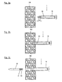
- the Fig. 1 shows an aerial bomb 1.
- the aerial bomb 1 has a standardized bomb shell 10.
- the bombshell 10 is the bombshell of the aerial bomb MK 82.
- the bombshell can also be the bombshell of the smaller aircraft bomb MK 81 or the larger aircraft bombs MK 83 or 84.
- the aerial bombs of MK types are explosive bombs.
- the bomb shell 10 is made of steel and has a smaller bow opening 11 and a larger rear opening 12. Unlike the explosive bomb in which the bomb shell is filled with explosive, now a slender penetrator 20 is disposed in the bomb shell 10.
- the mode of action of the aerial bomb 1 is in the Fig. 2a to 2c shown.
- the Fig. 2a shows an aerial bomb shortly before a target 100.
- the target 100 is a concrete target.
- the speed of the aerial bomb has a size of approx. 250 m / s.
- the bomb shell 10 and the penetrator 20 have the same speed at the beginning.
- the distance a between the tip of the penetrator 20 and the bow opening is greater than 100 mm, preferably greater than 150 mm.
- the distance a is also drawn. This distance a importantly ensures that the bomb shell 10 is still in front of the top of the penetrator on the target occurs.
- Fig. 2b indicates, takes place in the target a pre-damage, which is mainly caused by the structural strength of the bomb shell and the subsequent penetrator significantly facilitates the penetration of the target.
- the original explosive bomb contains a mass of about 90 kg explosive.
- the mass of the penetrator 20 corresponds to the mass of the explosive charge which was used in the explosive bomb designed as an aerial bomb.
- the mass of the penetrator therefore has a size of about 90 kg.
- the mass of the bomb shell 10 has a size of about 120 kg. Thus, a mass of about 3 kg remains for the further fastening parts, such as for the front spacer bushing 18 and the lid 80th
- the penetrator 20 is fixed in the bomb sheath 10 with a fixing agent.
- the fixing agent is mounting foam 30, whose mass is so small that it can be neglected in the mass design of the penetrator 20.
- the spacer bushing 18 centers the penetrator and facilitates assembly.
- the distance a between the tip of the penetrator 20 and the bow opening of the bomb sheath 10 should be at least so large that the front, provided in the standardized bomb sheath, slightly changed Igniter housing can be installed as a spacer sleeve 18. The slight change refers to a centering for the penetrator tip.
- the round rear opening 12 of the bomb cover 10 has a diameter of 150 mm.
- the maximum outer diameter of the penetrator 20 is smaller and has a size of about 140 mm, to allow installation over the rear opening 12.
- the maximum cross-sectional area of the penetrator 20 with a diameter of about 140 mm is greater than the cross-sectional area of the bow opening 11 with a diameter of about 80 mm. This results from the given boundary conditions, which pretend that the physical properties of the standard explosive bomb must not be changed.
- the maximum cross-sectional area of the penetrator is greater than the cross-sectional area of the bow opening.
- a minimum distance a is provided in order to generate a pre-damage to the target with the bomb envelope.
- penetrators are as slim as possible for a high level of effect in the target. Therefore, the distance a between the tip of the penetrator 20 and the bow opening 11 is smaller than 500 mm, preferably smaller than 300 mm.
- the distance b of the rear end of the penetrator to the rear end of the bomb cover 10 is smaller than 50 mm. In the exemplary embodiment, the distance b corresponds to the floor thickness of the rear-mounted cover 80.
- the penetrator 20 has an explosive charge 21 arranged in the rear.
- the mass fraction of the explosive charge 21 to the total mass of the penetrator 20 has a maximum size of 20%.
- the explosive charge 21 has a mass of about 10 kg.
- a fuze receiving socket 25 is arranged, which has the same dimensions as the detonator socket of the explosive bomb, from which the bomb shell is taken.
- the built-in detonator 90 in the aerial bomb is located.
- the ignition timing of the igniter 90 may be adjusted, for example, by the carrier aircraft. Either the ignition timing can coincide with the impact time or over a time delay after the impact time.
- Fig. 2c is the penetrator in a position that is suitable for ignition of the small explosive charge 21.
- the standardized bomb shell 10 has a receiving socket 14 for a wind turbine generator.
- a cable channel 26 is arranged, which extends from the Zünderinformationkuchse 25 to the bottom opening 15 of the receiving socket 14 of the wind turbine generator.
- the standardized bomb shell has a front mechanical interface 16 and a rear mechanical interface 17.
- a front steering device 40 or a rear steering device 50 may be mounted.
- the front steering device 40 may include a seeker head.
- the rear steering device may have a tail with adjustable wings.
Description
- Die Erfindung betrifft eine Fliegerbombe. Fliegerbomben werden ohne die Anbauteile, wie Zünder, Windradgenerator, Stromverbindungskabel, Lenkeinrichtungen und Aufhängeösen gelagert. Erst vor einem Einsatz werden die Anbauteile angebracht und die Fliegerbombe in einen betriebsbereiten Zustand überführt. In dieser Anmeldung gilt der Begriff Fliegerbombe in erster Linie für den Lagerungszustand, bei dem die vorgenannten Anbauteile noch nicht anmontiert sind.
- Neuentwicklungen von Fliegerbomben und ihre Integration in mögliche Plattformen sind extrem aufwändig. Eine Möglichkeit, die hierdurch verursachten Kosten zu reduzieren, besteht darin, sich an bestehenden Systemen zu orientieren. Von bestehenden Systemen sind die äußeren Abmessungen, die Masse, die Schwerpunktslage und die Massenträgheitsmomente um die Raumachsen bekannt. Diese Parameter bestimmen die aerodynamischen Eigenschaften. Ferner liegen die Aufhängepunkte zur Befestigung an der Trägerplattform vor. Schließlich sind die mechanischen Schnittstellen bekannt, um zum Beispiel die Lenkeinrichtungen anzubringen.
- Aus der
DE 697 30 252 T2 ist eine weiterentwickelte Fliegerbombe bekannt, welche dem Startpunkt für den Oberbegriff des Anspruchs 1 bildet. Diese Fliegerbombe orientiert sich an einer bekannten Sprengbombe. Die weiterentwickelte Fliegerbombe weist eine Umhüllung auf, deren äußere Abmessungen genau mit der bekannten Sprengbombe übereinstimmen. Ebenso stimmen die Masseneigenschaften mit der bekannten Sprengbombe überein. Innerhalb der Umhüllung ist ein Penetrator angeordnet, der im Heck eine Explosivstoffladung aufweist. Eine standardisierte Bombenhülle wiegt oftmals mehr als ein Drittel der Gesamtmasse einer Fliegerbombe und wird deshalb hier nicht eingesetzt. Vielmehr ist die Umhüllung ein neuentwickeltes Leichtbauteil, um dem Penetrator eine höhere Masse und damit eine höhere Wirksamkeit geben zu können. - Eine gattungsgemäße Fliegerbombe ist die Fliegerbombe BLU-126/B-. Die BLU-126/B-weist folgende Merkmale auf:
- die Fliegerbombe weist eine standardisierte Bombenhülle auf,
- die Bombenhülle ist die Bombenhülle der Fliegerbombe MK 82,
- die Bombenhülle besteht aus Stahl,
- die Bombenhülle weist eine kleinere Bugöffnung und eine größere Hecköffnung auf.
- Die Fliegerbombe ist aus dem Internet bekannt (http://de.wikipedia.org/wiki/Mk 82, 25. Februar 2008).
- Die Fliegerbombe BLU-126/B- stellt eine Variante der MK 82 dar. Die MK 82 ist die bei den US- und Nato-Streitkräften am häufigsten verwendete Sprengbombe. Die Fliegerbombe BLU-126/B- wurde auf Grund eines Wunsches der United States Navy nach einer Bombe für geringere Kolateralschäden bei Luftangriffen gebaut. Sie ist auch bekannt als "Low Collateral Damage Bomb (LCDB)". Um geringere Kolateralschäden zu erhalten, weist die BLU-126/B- eine kleinere Explosivstoffladung auf. Eine nicht explosive Füllung wird jedoch hinzugefügt, um die gleiche Masse wie vorher zu erhalten. Hierdurch wird erreicht, dass die aerodynamischen Eigenschaften der Bomben gleich bleiben.
- Der Erfindung liegt die Aufgabe zu Grunde, eine Fliegerbombe unter Verwendung einer standardisierten Bombenhülle aus Stahl zu schaffen, die im Zieleinschlag eine hohe Wirkung bei geringen Kolateralschäden aufweist.
- Diese Aufgabe wird erfindungsgemäß durch die Merkmale des Anspruches 1 gelöst.
- Die Fliegerbombe weist eine standardisierte Bombenhülle auf. Die Bombenhülle ist insbesondere die Bombenhülle der Fliegerbombe MK 81, 82, 83 oder 84. Derartige Bombenhüllen stehen in großer Anzahl zur Verfügung. Die Verwendung dieser Bombenhüllen reduziert die Kosten. Ferner liegt für diese Bombenhüllen eine Vielzahl von bereits fertig entwickelten und erprobten Anbauteilen vor, auf die zugegriffen werden kann. Auch dies reduziert die Kosten. Die Bombenhülle besteht aus Stahl und weist eine Bugöffnung und eine Hecköffnung auf. Dies sind die Rahmenbedingungen für einen schlanken Penetrator, der in der Bombenhülle angeordnet ist. Die für eine Sprengbombe konzipierte Bombenhülle dient nunmehr als Bombenhülle für einen Penetrator. Dadurch, dass der Abstand zwischen der Spitze des Penetrators und der Bugöffnung größer ist als 100 mm, wird in eine viel höhere Penetration des Penetrators erzielt, als erwartet. Dies wird dadurch erreicht, dass die Bombenhülle aus Stahl das Ziel vorschädigt. Aufgrund der Zielvorschädigung kann der Penetrator wesentlich tiefer in das Ziel eindringen. Die hohe mechanische Stabilität der Bombenhülle aus Stahl wird genutzt, um das Ziel zu schwächen und den Zieldurchschlag für den nachfolgenden Penetratorzu erleichtern. Bei dem Penetrator wird die Masse aufgrund seiner Schlankheit auf eine kleine Querschnittsfläche konzentriert. Eine kleinere Querschnittsfläche führt bei gleicher kinetischer Energie zu größeren Penetrationsleistungen. Da die Bombenhülle immer vor dem Penetrator Zielkontakt hat, wird das Eindringverhalten des Penetrators auch bei Auftreffwinkeln unterstützt.
- Ein Penetrator kann insbesondere dann als schlank betrachtet werden, wenn er eine Länge aufweist, die mehr als 7 mal so groß ist wie sein maximaler Außendurchmesser.
- Gemäß einer weiteren Ausgestaltung der Erfindung ist der Abstand zwischen der Spitze des Penetrators und der Bugöffnung kleiner als 500 mm. Hierdurch erreicht man, dass der Penetrator eine ausreichende Länge aufweist, um eine hohe Wirkung im Ziel zu gewährleisten.
- Gemäß einer weiteren Ausgestaltung der Erfindung ist der Abstand des Heckendes des Penetrators zum Heckende der Bombenhülle kleiner als 50 mm. Auch mit dieser Maßnahme ist eine ausreichende Länge des Penetrators verbunden mit einer hohen Wirkung im Ziel gewährleistet.
- Gemäß einer weiteren Ausgestaltung der Erfindung entspricht die Masse des Penetrators im Wesentlichen der Masse der Explosivstoffladung, die in der als Sprengbombe ausgebildeten Fliegerbombe eingesetzt ist. Mit dieser Maßnahme erreicht man, dass der Penetrator die maximal mögliche Masse erhält. Der Penetrator ersetzt die frühere Explosivstoffladung nahezu vollständig.
- Gemäß einer weiteren Ausgestaltung der Erfindung ist die maximale Querschnittsfläche des Penetrators kleiner als die Querschnittsfläche der Hecköffnung der Bombenhülle. Dies erleichtert den Einbau des Penetrators in die Bombenhülle. Bei der Montage lässt sich der Penetrator durch die Hecköffnung in die Bombenhülle einführen.
- Gemäß einer weiteren Ausgestaltung der Erfindung ist die maximale Querschnittfläche des Penetrators größer als die Querschnittsfläche der Bugöffnung. Diese Maßnahme bedeutet einerseits einen Nachteil dahingehend, dass der Penetrator die engere Bugöffnung der Bombenhülle aufweiten muss. Andererseits überwiegen die Vorteile, die darin liegen, dass bei den vorliegenden Rahmenbedingungen, die noch im Ausführungsbeispiel diskutiert werden, der Penetrator seine maximal mögliche Masse erhält.
- Gemäß einer weiteren Ausgestaltung der Erfindung weist der Penetrator eine im Heck angeordnete Explosivstoffladung auf. Die Explosivstoffladung kann zum Zeitpunkt des Zieleinschlages oder zeitverzögert gezündet werden. Mit der Explosivstoffladung soll eine örtlich begrenzte Wirkung erzielt werden. Kolateralschäden sollen vermieden werden.
- Gemäß einer weiteren Ausgestaltung der Erfindung beträgt der Massenanteil der Explosivstoffladung zur Gesamtmasse des Penetrators eine Größe von maximal 20 %. Hierdurch wird der Schwerpunkt der Wirkung auf die Penetration gelegt, wobei die Wirkung der Splitter des Penetrators und der Splitter der Bombenhülle aufgrund der sehr kleinen Explosivstoffladung begrenzt ist.
- Gemäß einer weiteren Ausgestaltung der Erfindung ist in der Explosivladung des Penetrators eine Zünderaufnahmebuchse angeordnet, die die gleichen Abmessungen aufweist, wie die Zünderaufnahmebuchse der Sprengbombe. Für einen Soldaten bedeutet dies eine einfache Handhabung. Er hat im Rahmen der Einsatzbereitmachung auf die gleiche Art und Weise den Zünder in die Zünderaufnahmebuchse einzusetzen, wie bei der bisherigen Sprengbombe.
- Gemäß einer weiteren Ausgestaltung der Erfindung weist die Bombenhülle eine Aufnahmebuchse für einen Windradgenerator auf, wobei in dem Penetrator ein Kabelkanal angeordnet ist, der von der Zünderaufnahmebuchse bis zu der Bodenöffnung der Aufnahmebuchse des Windradgenerators verläuft. Genau wie bei der bisherigen Sprengbombe ist zur Einsatzbereitmachung ein Verbindungskabei in dem Kabelkanal zu verlegen und ein Windradgenerator zu montieren.
- Gemäß einer weiteren Ausgestaltung der Erfindung ist der Penetrator mit einem Fixierungsmittel in der Bombenhülle fixiert. Das Fixierungsmittel fixiert die Lage des Penetrators während der Lagerung, des Transports und im Einsatz bis zum Auftreffen auf das Ziel.
- Gemäß einer weiteren Ausgestaltung der Erfindung ist das Fixierungsmittel Montageschaum. Dies stellt eine kostengünstige Maßnahme dar. Die Masse des Montageschaums ist bezogen auf die Gesamtmasse unbedeutend.
- Gemäß einer weiteren Ausgestaltung der Erfindung weist die standardisierte Bombenhülle mechanische Schnittstellen auf, über die vor einem Einsatz Lenkeinrichtungen anmontierbar sind. Vorhandene, standardisierte Lenkeinrichtungen der bisherigen Sprengbombe können eingesetzt werden.
- Ein Ausführungsbeispiel der Erfindung wird nachfolgend an Hand der Zeichnungen näher beschrieben. Dabei zeigen:
- Fig. 1
- eine Fliegerbombe mit Penetrator im Längsschnitt;
- Fig. 2 a bis 2 c
- die einzelnen Schritte des Durchdringens eines Zieles, wobei der Wirkmechanismus illustriert ist.
- Die
Fig. 1 zeigt eine Fliegerbombe 1. Die Fliegerbombe 1 weist eine standardisierte Bombenhülle 10 auf. Die Bombenhülle 10 ist die Bombenhülle der Fliegerbombe MK 82. In Abweichung hierzu kann die Bombenhülle auch die Bombenhülle der kleineren Fliegerbombe MK 81 oder der größeren Fliegerbomben MK 83 oder 84 sein. Die Fliegerbomben der MK-Typen sind Sprengbomben. Die Bombenhülle 10 besteht aus Stahl und weist eine kleinere Bugöffnung 11 und eine größere Hecköffnung 12 auf. Anders als bei der Sprengbombe, bei der die Bombenhülle mit Explosivstoff gefüllt ist, ist jetzt ein schlanker Penetrator 20 in der Bombenhülle 10 angeordnet. - Die Wirkungsweise der Fliegerbombe 1 ist in den
Fig. 2a bis 2c dargestellt. - Die
Fig. 2a zeigt eine Fliegerbombe kurz vor einem Ziel 100. Das Ziel 100 ist ein Betonziel. Die Geschwindigkeit der Fliegerbombe hat eine Größe von ca. 250 m/s. Die Bombenhülle 10 und der Penetrator 20 weisen am Anfang die gleiche Geschwindigkeit auf. Der Abstand a zwischen der Spitze des Penetrators 20 und der Bugöffnung ist größer als 100 mm, vorzugsweise größer als 150 mm. In der vergrößerten Darstellung der Fliegerbombe nachFig. 1 ist der Abstand a ebenfalls eingezeichnet. Dieser Abstand a sorgt in wichtiger Weise dafür, dass die Bombenhülle 10 noch vor der Spitze des Penetrators auf das Ziel auftritt. WieFig. 2b andeutet, findet im Ziel eine Vorschädigung statt, die im Wesentlichen durch die Strukturfestigkeit der Bombenhülle hervorgerufen wird und die dem nachfolgenden Penetrator das Durchdringen des Zieles deutlich erleichtert. - Die Gesamtmasse der Fliegerbombe mit Penetrator nach
Fig. 1 hat, wie auch bei der ursprünglichen Sprengbombe, eine Größe von ca. 213 kg. Die Masse bezieht sich auf den Lagerungszustand, bei dem die Anbauteile noch nicht anmontiert sind. Für die inFig. 1 dargestellte Fliegerbombe 1 mit Penetrator 20 können die gleichen, standardisierten Anbauteile verwendet werden wie bei der ursprünglichen Sprengbombe. Die Anbauteile sind: - der Zünder (nicht eingezeichnet), der seinen Platz in der Zünderaufnahmebuchse 25 einnimmt,
- der Windradgenerator 60 in der Aufnahmebuchse 14,
- das Stromverbindungskabel (nicht eingezeichnet), das in dem Kabelkanal 26 ,
- die vordere Lenkeinrichtung 40, die einen Suchkopf aufweisen kann und über die mechanische Schnittstelle 16 befestigt ist,
- die hintere Lenkeinrichtung 50, die ein Leitwerk mit Lenkflügeln aufweist und über die mechanischen Schnittstelle 17 gehalten ist und
- die Aufhängeösen 70a und 70b zur Anbringung an die Trägerplattform.
- Die ursprüngliche Sprengbombe enthält eine Masse von ca. 90 kg Explosivstoff. Die Masse des Penetrators 20 entspricht der Masse der Explosivstoffladung, die in der als Sprengbombe ausgebildeten Fliegerbombe eingesetzt war. Die Masse des Penetrators hat demnach eine Größe von ca. 90 kg.
- Die Masse der Bombenhülle 10 hat eine Größe von ca. 120 kg. Somit verbleibt eine Masse von ca. 3 kg für die weiteren Befestigungsteile, wie zum Beispiel für die vordere Abstandshalterbuchse 18 und den Deckel 80.
- Der Penetrator 20 ist mit einem Fixierungsmittel in der Bombenhülle 10 fixiert. Das Fixierungsmittel ist Montageschaum 30, dessen Masse so klein ist, dass sie bei der Massenauslegung des Penetrators 20 vernachlässigt werden kann. Die Abstandshalterbuchse 18 zentriert den Penetrator und erleichtert die Montage. Vorzugsweise sollte der Abstand a zwischen der Spitze des Penetrators 20 und der Bugöffnung der Bombenhülle 10 mindestens so groß gewählt werden, dass das vordere, in der standardisierten Bombenhülle vorgesehene, geringfügig veränderte Zündergehäuse als Abstandshalterbuchse 18 eingebaut werden kann. Die geringfügige Veränderung bezieht sich auf eine Zentrierung für die Penetratorspitze.
- Die runde Hecköffnung 12 der Bombenhülle 10 weist einen Durchmesser von 150 mm auf. Der maximale Außendurchmesser des Penetrators 20 ist kleiner und hat eine Größe von ca. 140 mm, um einen Einbau über die Hecköffnung 12 zu ermöglichen.
- In dem vorliegenden Ausführungsbeispiel, bei dem die standardisierte Bombenhülle der MK 82 Sprengbombe eingesetzt ist, ist die maximale Querschnittsfläche des Penetrators 20 mit einem Durchmesser von ca. 140 mm größer als die Querschnittsfläche der Bugöffnung 11 mit einem Durchmesser von ca. 80 mm. Dies resultiert aus den vorgegebenen Randbedingungen, die vorgeben, dass die physikalischen Eigenschaften der Standardsprengbombe nicht verändert werden dürfen.
- Auch bei einer Verwendung der MK 81, MK 83 oder MK 84 Bombenhülle ist die maximale Querschnittsfläche des Penetrators größer als die Querschnittsfläche der Bugöffnung.
- Untersuchungen haben gezeigt, dass die konische Spitze des Penetrators die Bugöffnung der stabilen Bombenhülle problemlos aufreißen kann. Die Verluste für die Überwindung der radialen Strukturfestigkeit des vorderen, stabilen Ringquerschnitts sind geringer als erwartet.
- Wie an Hand der
Fig. 2a bis 2c illustriert, ist einerseits ein Mindestabstand a vorgesehen, um mit der auftreffenden Bombenhülle eine Vorschädigung des Zieles zu erzeugen. Andererseits sind Penetratoren für eine hohe Wirkung im Ziel möglichst schlank. Daher ist der Abstand a zwischen der Spitze des Penetrators 20 und der Bugöffnung 11 kleiner als 500 mm, vorzugsweise kleiner als 300 mm. Aus dem gleichen Grund ist der Abstand b des Heckendes des Penetrators zum Heckende der Bombenhülle 10 kleiner als 50 mm. In dem Ausführungsbeispiel entspricht der Abstand b der Bodendicke des am Heck montierten Deckels 80. - Der Penetrator 20 weist eine im Heck angeordnete Explosivstoffladung 21 auf. Der Massenanteil der Explosivstoffladung 21 zur Gesamtmasse des Penetrators 20 hat eine Größe von maximal 20 %. Im Ausführungsbeispiel weist die Explosivstoffladung 21 eine Masse von ca. 10 kg auf.
- In der Penetratorladung 21 ist eine Zünderaufnahmebuchse 25 angeordnet, die die gleichen Abmessungen aufweist, wie die Zünderaufnahmebuchse der Sprengbombe, von der die Bombenhülle übernommen ist. In
Fig. 2c ist der in der Fliegerbombe eingebaute Zünder 90 eingezeichnet. Der Zündzeitpunkt des Zünders 90 kann beispielsweise vom Trägerflugzeug aus eingestellt werden. Entweder kann der Zündzeitpunkt mit dem Aufschlagzeitpunkt zusammentreffen oder über eine Zeitverzögerung nach dem Aufschlagzeitpunkt erfolgen. InFig. 2c ist der Penetrator in einer Position, die für eine Zündung der kleinen Explosivstoffladung 21 geeignet ist. - Die standardisierte Bombenhülle 10 weist eine Aufnahmebuchse 14 für einen Windradgenerator auf. In dem Penetrator 20 ist ein Kabelkanal 26 angeordnet, der von der Zünderaufnahmebuchse 25 bis zu der Bodenöffnung 15 der Aufnahmebuchse 14 des Windradgenerators verläuft.
- Die standardisierte Bombenhülle weist eine vordere mechanische Schnittstelle 16 und eine hintere mechanische Schnittstelle 17 auf. Vor einem Einsatz können eine vordere Lenkeinrichtung 40 oder eine hintere Lenkeinrichtung 50 montiert werden. Die vordere Lenkeinrichtung 40 kann einen Suchkopf enthalten. Die hintere Lenkeinrichtung kann ein Leitwerk mit verstellbaren Flügeln besitzen.
-
- 1
- Fliegerbombe
- 10
- Bombenhülle
- 11
- Bugöffnung
- 12
- Hecköffnung
- 14
- Aufnahmebuchse für einen Windradgenerator
- 15
- Bodenöffnung der Aufnahmebuchse
- 16
- vordere mechanische Schnittstelle
- 17
- hintere mechanische Schnittstelle
- 18
- Abstandshalterbuchse
- 20
- Penetrator
- 21
- Explosivstoffladung
- 25
- Zündaufnahmebuchse
- 26
- Kabelkanal
- 30
- Montageschaum
- 40
- vordere Lenkeinrichtung
- 50
- hintere Lenkeinrichtung
- 60
- Windradgenerator
- 70a, 70b
- Aufhängeösen
- 80
- Deckel
- 90
- Zünder
- 100
- Ziel
- a
- Abstand zwischen der Spitze des Penetrators und der Bugöffnung
- b
- Abstand des Heckendes des Penetrators zum Heckende der Bombenhülle
Claims (13)
- Fliegerbombe (1), mit folgenden Merkmalen:• die Fliegerbombe (1) weist eine Bombenhülle (10) auf, insbesondere die Bombenhülle der Fliegerbombe MK 81, 82, 83 oder 84,• die Bombenhülle weist eine Bugöffnung (11) und eine Hecköffnung (12) auf,• ein schlanker Penetrator (20) ist in der Bombenhülle (10) angeordnet,
dadurch gekennzeichnet,• dass die Fliegerbombe (1) eine standardisierte Bombenhülle (10) aufweist,
und• dass die Bombenhülle (10) aus Stahl besteht,
und• dass der Abstand (a) zwischen der Spitze des Penetrators (20) und der vorderen Bugöffnung größer als 100 mm ist. - Fliegerbombe nach Anspruch 1,
dadurch gekennzeichnet,
dass der Abstand (a) zwischen der Spitze des Penetrators (20) und der vorderen Bugöffnung (11) kleiner als 500 mm ist. - Fliegerbombe nach Anspruch 1 oder 2,
dadurch gekennzeichnet,
dass der Abstand (b) des Heckendes des Penetrators (20) zum Heckende der Bombenhülle (10) kleiner als 50 mm ist. - Fliegerbombe nach einem der Ansprüche 1 bis 3,
dadurch gekennzeichnet,
dass die Masse des Penetrators (20) im Wesentlichen der Masse der Explosivstoffladung entspricht, die in der als Sprengbombe ausgebildeten Fliegerbombe eingesetzt ist. - Fliegerbombe nach einem der Ansprüche 1 bis 4,
dadurch gekennzeichnet,
dass die maximale Querschnittsfläche des Penetrators (20) kleiner ist als die Querschnittsfläche der Hecköffnung (12) der Bombenhülle (10). - Fliegerbombe nach einem der Ansprüche 1 bis 5,
dadurch gekennzeichnet,
dass die maximale Querschnittfläche des Penetrators (20) größer ist als die Querschnittsfläche der Bugöffnung (11). - Fliegerbombe nach einem der Ansprüche 1 bis 6,
dadurch gekennzeichnet,
dass der Penetrator (20) eine im Heck angeordnete Explosivstoffladung (21) aufweist. - Fliegerbombe nach Anspruch 7,
dadurch gekennzeichnet,
dass der Massenanteil der Explosivstoffladung (21) zur Gesamtmasse des Penetrators (20) eine Größe von maximal 20 % einnimmt. - Fliegerbombe nach Anspruch 7 oder 8,
dadurch gekennzeichnet,
dass in der Explosivstoffladung (21) eine Zünderaufnahmebuchse (25) angeordnet ist, die die gleichen Abmessungen aufweist, wie die Zünderaufnahmebuchse der Sprengbombe. - Fliegerbombe nach einem der Ansprüche 7 bis 9,
dadurch gekennzeichnet,
dass die standardisierte Bombenhülle (10) eine Aufnahmebuchse (14) für einen Windradgenerator (60) aufweist und dass in dem Penetrator (20) ein Kabelkanal (26) angeordnet ist, der von der Zünderaufnahmebuchse (25) bis zu der Bodenöffnung (15) der Aufnahmebuchse (14) des Windradgenerators (60) verläuft. - Fliegerbombe nach einem der Ansprüche 1 bis 10,
dadurch gekennzeichnet,
dass der Penetrator (20) mit einem Fixierungsmittel in der Bombenhülle (10) fixiert ist. - Fliegerbombe nach Anspruch 11,
dadurch gekennzeichnet,
dass das Fixierungsmittel Montageschaum (30) ist. - Fliegerbombe nach einem der Ansprüche 1 bis 12,
dadurch gekennzeichnet,
dass die Bombenhülle (10) mechanische Schnittstellen (16, 17) aufweist, über die vor einem Einsatz Lenkeinrichtungen (40, 50) anmontierbar sind.
Applications Claiming Priority (1)
| Application Number | Priority Date | Filing Date | Title |
|---|---|---|---|
| PCT/EP2009/007887 WO2011054361A1 (de) | 2009-11-04 | 2009-11-04 | Fliegerbombe |
Publications (2)
| Publication Number | Publication Date |
|---|---|
| EP2496908A1 EP2496908A1 (de) | 2012-09-12 |
| EP2496908B1 true EP2496908B1 (de) | 2013-09-11 |
Family
ID=42269610
Family Applications (1)
| Application Number | Title | Priority Date | Filing Date |
|---|---|---|---|
| EP09749015.5A Active EP2496908B1 (de) | 2009-11-04 | 2009-11-04 | Fliegerbombe |
Country Status (7)
| Country | Link |
|---|---|
| US (1) | US8689694B2 (de) |
| EP (1) | EP2496908B1 (de) |
| DK (1) | DK2496908T3 (de) |
| ES (1) | ES2437341T3 (de) |
| IL (1) | IL218551A (de) |
| WO (1) | WO2011054361A1 (de) |
| ZA (1) | ZA201203973B (de) |
Cited By (2)
| Publication number | Priority date | Publication date | Assignee | Title |
|---|---|---|---|---|
| DE202015004089U1 (de) | 2015-06-02 | 2015-08-04 | Bundesrepublik Deutschland, vertreten durch das Bundesministerium der Verteidigung, dieses vertreten durch das Bundesamt für Ausrüstung, Informationstechnik und Nutzung der Bundeswehr | Penetrator |
| US9587921B2 (en) | 2013-05-31 | 2017-03-07 | Robert T. Faxon | Warhead casings and methods of manufacture |
Families Citing this family (6)
| Publication number | Priority date | Publication date | Assignee | Title |
|---|---|---|---|---|
| WO2015175038A2 (en) | 2014-02-11 | 2015-11-19 | Raytheon Company | Penetrator munition with enhanced fragmentation |
| US9810513B2 (en) | 2014-08-04 | 2017-11-07 | Raytheon Company | Munition modification kit and method of modifying munition |
| US9739583B2 (en) | 2014-08-07 | 2017-08-22 | Raytheon Company | Fragmentation munition with limited explosive force |
| US9909848B2 (en) | 2015-11-16 | 2018-03-06 | Raytheon Company | Munition having penetrator casing with fuel-oxidizer mixture therein |
| US10132603B2 (en) * | 2016-12-23 | 2018-11-20 | Darren J. Kennedy | Projectile device fired in a flight trajectory towards a target |
| RU191465U1 (ru) * | 2019-01-18 | 2019-08-07 | Евгений Николаевич Коптяев | Атомная бомба |
Family Cites Families (14)
| Publication number | Priority date | Publication date | Assignee | Title |
|---|---|---|---|---|
| FR2339833A1 (fr) | 1976-01-30 | 1977-08-26 | Thomson Brandt | Corps perforant de projectile et munition equipee d'un tel corps |
| DE19535218C1 (de) | 1995-09-22 | 1997-02-27 | Diehl Gmbh & Co | Ballistisches Geschoß |
| DE19600167C1 (de) | 1996-01-04 | 2003-07-17 | Diehl Stiftung & Co | Penetrator |
| US5939662A (en) | 1997-12-03 | 1999-08-17 | Raytheon Company | Missile warhead design |
| US6389977B1 (en) | 1997-12-11 | 2002-05-21 | Lockheed Martin Corporation | Shrouded aerial bomb |
| US6408762B1 (en) | 1997-12-11 | 2002-06-25 | Lockheed Martin Corporation | Clamp assembly for shrouded aerial bomb |
| IL136676A (en) | 1997-12-11 | 2003-03-12 | Lockheed Corp | Shrouded aerial bomb |
| US6276277B1 (en) * | 1999-04-22 | 2001-08-21 | Lockheed Martin Corporation | Rocket-boosted guided hard target penetrator |
| US6374744B1 (en) * | 2000-05-25 | 2002-04-23 | Lockheed Martin Corporation | Shrouded bomb |
| ES2330223T3 (es) * | 2003-07-04 | 2009-12-07 | Industria Meccanica Zane' S.R.L. | Metodo de fabricacion de dispositivos balisticos inertes para entrenamiento y dispositivo balistico fabricado conforme a dicho metodo. |
| FR2871226B1 (fr) * | 2004-06-08 | 2006-08-18 | Tda Armements Sas Soc Par Acti | Projectile, notamment bombe de penetration anti- infrastructure et procede de penetration d'un tel projectile a travers une paroi |
| FR2887021B1 (fr) * | 2005-06-14 | 2007-08-31 | Tda Armements Sas Soc Par Acti | Kit d'aide a la penetration equipant une bombe, notamment anti-infrastructure, projectile penetrant equipe d'un tel kit, et procede de penetration dans une cible |
| US7886668B2 (en) * | 2006-06-06 | 2011-02-15 | Lockheed Martin Corporation | Metal matrix composite energetic structures |
| FR2910612B1 (fr) * | 2006-12-21 | 2009-10-02 | Ateliers Mecaniques De Pont Su | Bombe aerienne de penetration munie d'un revetement externe. |
-
2009
- 2009-11-04 WO PCT/EP2009/007887 patent/WO2011054361A1/de active Application Filing
- 2009-11-04 DK DK09749015.5T patent/DK2496908T3/da active
- 2009-11-04 ES ES09749015.5T patent/ES2437341T3/es active Active
- 2009-11-04 EP EP09749015.5A patent/EP2496908B1/de active Active
-
2012
- 2012-03-08 IL IL218551A patent/IL218551A/en active IP Right Grant
- 2012-05-04 US US13/463,988 patent/US8689694B2/en active Active
- 2012-05-31 ZA ZA2012/03973A patent/ZA201203973B/en unknown
Cited By (2)
| Publication number | Priority date | Publication date | Assignee | Title |
|---|---|---|---|---|
| US9587921B2 (en) | 2013-05-31 | 2017-03-07 | Robert T. Faxon | Warhead casings and methods of manufacture |
| DE202015004089U1 (de) | 2015-06-02 | 2015-08-04 | Bundesrepublik Deutschland, vertreten durch das Bundesministerium der Verteidigung, dieses vertreten durch das Bundesamt für Ausrüstung, Informationstechnik und Nutzung der Bundeswehr | Penetrator |
Also Published As
| Publication number | Publication date |
|---|---|
| US20120291651A1 (en) | 2012-11-22 |
| DK2496908T3 (da) | 2013-12-09 |
| IL218551A0 (en) | 2012-05-31 |
| ES2437341T3 (es) | 2014-01-10 |
| US8689694B2 (en) | 2014-04-08 |
| EP2496908A1 (de) | 2012-09-12 |
| WO2011054361A1 (de) | 2011-05-12 |
| IL218551A (en) | 2015-01-29 |
| ZA201203973B (en) | 2013-02-27 |
Similar Documents
| Publication | Publication Date | Title |
|---|---|---|
| EP2496908B1 (de) | Fliegerbombe | |
| DE7719490U1 (de) | Projektil | |
| EP0113833B1 (de) | Spreng- und Brandgeschoss | |
| DE10205043B4 (de) | Aus einem Rohr zu verschließender Flugkörper mit überkalibrigem Leitwerk | |
| DE2845414A1 (de) | Beim ueberfliegen des ziels wirksam werdendes geschoss | |
| DE69730252T2 (de) | Flugzeugbombe mit einer nasenumhüllung | |
| DE102008023678B4 (de) | Fliegerbombe | |
| DE19917144B4 (de) | Kombinationswirksystem | |
| EP3507565B1 (de) | Geschoss mit penetrator | |
| DE3617415C2 (de) | Unterkalibriges Treibspiegelgeschoß | |
| DE102018103753A1 (de) | Vorrichtung und Verfahren zur Beseitigung eines nicht explo-dierten Kampfmittels unter Wasser | |
| DE19948710B4 (de) | Flügelstabilisiertes Wuchtgeschoß | |
| EP0485897B1 (de) | Bahnkorrigierbares Projektil | |
| EP1682848B1 (de) | Struktur eines geschosses | |
| DE102016007976A1 (de) | Vorfragmentierung eines Sprengkopfes | |
| DE1578089B1 (de) | Gefechtskopf fuer einen raketengetriebenen Flugkoerper oder ein Geschoss zur Bekaempfung von gepanzerten Zielen | |
| DE19612890C2 (de) | Mörsergeschoß | |
| DE3432650A1 (de) | Unterkalibriertes projektil vom pfeiltyp | |
| EP3156757B1 (de) | Waffensystem und verfahren zum betreiben eines waffensystems | |
| DE4135780C2 (de) | Pfeil-Wuchtgeschoß | |
| EP1617169B1 (de) | Einrichtung zur Tiefensteuerung für einen Spulenaufschwimmkörper | |
| DE2105957A1 (de) | Geschoß | |
| DE102012000893B4 (de) | Retardierend zerlegende Geschosshülle | |
| DE975806C (de) | Gewehrgranate | |
| DE1578089C2 (de) | Gefechtskopf für einen raketengetriebenen Flugkörper oder ein Geschoß zur Bekämpfung von gepanzerten Zielen |
Legal Events
| Date | Code | Title | Description |
|---|---|---|---|
| PUAI | Public reference made under article 153(3) epc to a published international application that has entered the european phase |
Free format text: ORIGINAL CODE: 0009012 |
|
| 17P | Request for examination filed |
Effective date: 20120220 |
|
| AK | Designated contracting states |
Kind code of ref document: A1 Designated state(s): AT BE BG CH CY CZ DE DK EE ES FI FR GB GR HR HU IE IS IT LI LT LU LV MC MK MT NL NO PL PT RO SE SI SK SM TR |
|
| DAX | Request for extension of the european patent (deleted) | ||
| GRAP | Despatch of communication of intention to grant a patent |
Free format text: ORIGINAL CODE: EPIDOSNIGR1 |
|
| INTG | Intention to grant announced |
Effective date: 20130423 |
|
| RBV | Designated contracting states (corrected) |
Designated state(s): AT BE BG CH CY CZ DK EE ES FI FR GB GR HR HU IE IS IT LI LT LU LV MC MK MT NL NO PL PT RO SE SI SK SM TR |
|
| REG | Reference to a national code |
Ref country code: DE Ref legal event code: R108 |
|
| GRAS | Grant fee paid |
Free format text: ORIGINAL CODE: EPIDOSNIGR3 |
|
| GRAA | (expected) grant |
Free format text: ORIGINAL CODE: 0009210 |
|
| REG | Reference to a national code |
Ref country code: DE Ref legal event code: R108 Effective date: 20130710 |
|
| AK | Designated contracting states |
Kind code of ref document: B1 Designated state(s): AT BE BG CH CY CZ DK EE ES FI FR GB GR HR HU IE IS IT LI LT LU LV MC MK MT NL NO PL PT RO SE SI SK SM TR |
|
| REG | Reference to a national code |
Ref country code: GB Ref legal event code: FG4D Free format text: NOT ENGLISH |
|
| REG | Reference to a national code |
Ref country code: CH Ref legal event code: EP |
|
| REG | Reference to a national code |
Ref country code: AT Ref legal event code: REF Ref document number: 631888 Country of ref document: AT Kind code of ref document: T Effective date: 20130915 |
|
| REG | Reference to a national code |
Ref country code: IE Ref legal event code: FG4D Free format text: LANGUAGE OF EP DOCUMENT: GERMAN |
|
| REG | Reference to a national code |
Ref country code: DK Ref legal event code: T3 Effective date: 20131202 |
|
| REG | Reference to a national code |
Ref country code: SE Ref legal event code: TRGR |
|
| REG | Reference to a national code |
Ref country code: NL Ref legal event code: T3 |
|
| REG | Reference to a national code |
Ref country code: ES Ref legal event code: FG2A Ref document number: 2437341 Country of ref document: ES Kind code of ref document: T3 Effective date: 20140110 |
|
| REG | Reference to a national code |
Ref country code: NO Ref legal event code: T2 Effective date: 20130911 |
|
| PG25 | Lapsed in a contracting state [announced via postgrant information from national office to epo] |
Ref country code: CY Free format text: LAPSE BECAUSE OF FAILURE TO SUBMIT A TRANSLATION OF THE DESCRIPTION OR TO PAY THE FEE WITHIN THE PRESCRIBED TIME-LIMIT Effective date: 20130911 Ref country code: HR Free format text: LAPSE BECAUSE OF FAILURE TO SUBMIT A TRANSLATION OF THE DESCRIPTION OR TO PAY THE FEE WITHIN THE PRESCRIBED TIME-LIMIT Effective date: 20130911 Ref country code: LT Free format text: LAPSE BECAUSE OF FAILURE TO SUBMIT A TRANSLATION OF THE DESCRIPTION OR TO PAY THE FEE WITHIN THE PRESCRIBED TIME-LIMIT Effective date: 20130911 |
|
| REG | Reference to a national code |
Ref country code: LT Ref legal event code: MG4D |
|
| REG | Reference to a national code |
Ref country code: GR Ref legal event code: EP Ref document number: 20130402640 Country of ref document: GR Effective date: 20140124 |
|
| PG25 | Lapsed in a contracting state [announced via postgrant information from national office to epo] |
Ref country code: LV Free format text: LAPSE BECAUSE OF FAILURE TO SUBMIT A TRANSLATION OF THE DESCRIPTION OR TO PAY THE FEE WITHIN THE PRESCRIBED TIME-LIMIT Effective date: 20130911 Ref country code: SI Free format text: LAPSE BECAUSE OF FAILURE TO SUBMIT A TRANSLATION OF THE DESCRIPTION OR TO PAY THE FEE WITHIN THE PRESCRIBED TIME-LIMIT Effective date: 20130911 |
|
| PG25 | Lapsed in a contracting state [announced via postgrant information from national office to epo] |
Ref country code: EE Free format text: LAPSE BECAUSE OF FAILURE TO SUBMIT A TRANSLATION OF THE DESCRIPTION OR TO PAY THE FEE WITHIN THE PRESCRIBED TIME-LIMIT Effective date: 20130911 Ref country code: IS Free format text: LAPSE BECAUSE OF FAILURE TO SUBMIT A TRANSLATION OF THE DESCRIPTION OR TO PAY THE FEE WITHIN THE PRESCRIBED TIME-LIMIT Effective date: 20140111 Ref country code: SK Free format text: LAPSE BECAUSE OF FAILURE TO SUBMIT A TRANSLATION OF THE DESCRIPTION OR TO PAY THE FEE WITHIN THE PRESCRIBED TIME-LIMIT Effective date: 20130911 Ref country code: CZ Free format text: LAPSE BECAUSE OF FAILURE TO SUBMIT A TRANSLATION OF THE DESCRIPTION OR TO PAY THE FEE WITHIN THE PRESCRIBED TIME-LIMIT Effective date: 20130911 Ref country code: RO Free format text: LAPSE BECAUSE OF FAILURE TO SUBMIT A TRANSLATION OF THE DESCRIPTION OR TO PAY THE FEE WITHIN THE PRESCRIBED TIME-LIMIT Effective date: 20130911 |
|
| PG25 | Lapsed in a contracting state [announced via postgrant information from national office to epo] |
Ref country code: PL Free format text: LAPSE BECAUSE OF FAILURE TO SUBMIT A TRANSLATION OF THE DESCRIPTION OR TO PAY THE FEE WITHIN THE PRESCRIBED TIME-LIMIT Effective date: 20130911 |
|
| PG25 | Lapsed in a contracting state [announced via postgrant information from national office to epo] |
Ref country code: PT Free format text: LAPSE BECAUSE OF FAILURE TO SUBMIT A TRANSLATION OF THE DESCRIPTION OR TO PAY THE FEE WITHIN THE PRESCRIBED TIME-LIMIT Effective date: 20140113 |
|
| REG | Reference to a national code |
Ref country code: CH Ref legal event code: PL |
|
| PLBE | No opposition filed within time limit |
Free format text: ORIGINAL CODE: 0009261 |
|
| STAA | Information on the status of an ep patent application or granted ep patent |
Free format text: STATUS: NO OPPOSITION FILED WITHIN TIME LIMIT |
|
| PG25 | Lapsed in a contracting state [announced via postgrant information from national office to epo] |
Ref country code: MC Free format text: LAPSE BECAUSE OF FAILURE TO SUBMIT A TRANSLATION OF THE DESCRIPTION OR TO PAY THE FEE WITHIN THE PRESCRIBED TIME-LIMIT Effective date: 20130911 Ref country code: CH Free format text: LAPSE BECAUSE OF NON-PAYMENT OF DUE FEES Effective date: 20131130 Ref country code: LI Free format text: LAPSE BECAUSE OF NON-PAYMENT OF DUE FEES Effective date: 20131130 |
|
| 26N | No opposition filed |
Effective date: 20140612 |
|
| GBPC | Gb: european patent ceased through non-payment of renewal fee |
Effective date: 20131211 |
|
| REG | Reference to a national code |
Ref country code: IE Ref legal event code: MM4A |
|
| PG25 | Lapsed in a contracting state [announced via postgrant information from national office to epo] |
Ref country code: IE Free format text: LAPSE BECAUSE OF NON-PAYMENT OF DUE FEES Effective date: 20131104 |
|
| PG25 | Lapsed in a contracting state [announced via postgrant information from national office to epo] |
Ref country code: GB Free format text: LAPSE BECAUSE OF NON-PAYMENT OF DUE FEES Effective date: 20131211 |
|
| PG25 | Lapsed in a contracting state [announced via postgrant information from national office to epo] |
Ref country code: SM Free format text: LAPSE BECAUSE OF FAILURE TO SUBMIT A TRANSLATION OF THE DESCRIPTION OR TO PAY THE FEE WITHIN THE PRESCRIBED TIME-LIMIT Effective date: 20130911 |
|
| PG25 | Lapsed in a contracting state [announced via postgrant information from national office to epo] |
Ref country code: BG Free format text: LAPSE BECAUSE OF FAILURE TO SUBMIT A TRANSLATION OF THE DESCRIPTION OR TO PAY THE FEE WITHIN THE PRESCRIBED TIME-LIMIT Effective date: 20130911 Ref country code: LU Free format text: LAPSE BECAUSE OF NON-PAYMENT OF DUE FEES Effective date: 20131104 Ref country code: MK Free format text: LAPSE BECAUSE OF FAILURE TO SUBMIT A TRANSLATION OF THE DESCRIPTION OR TO PAY THE FEE WITHIN THE PRESCRIBED TIME-LIMIT Effective date: 20130911 Ref country code: HU Free format text: LAPSE BECAUSE OF FAILURE TO SUBMIT A TRANSLATION OF THE DESCRIPTION OR TO PAY THE FEE WITHIN THE PRESCRIBED TIME-LIMIT; INVALID AB INITIO Effective date: 20091104 |
|
| PG25 | Lapsed in a contracting state [announced via postgrant information from national office to epo] |
Ref country code: MT Free format text: LAPSE BECAUSE OF FAILURE TO SUBMIT A TRANSLATION OF THE DESCRIPTION OR TO PAY THE FEE WITHIN THE PRESCRIBED TIME-LIMIT Effective date: 20130911 |
|
| REG | Reference to a national code |
Ref country code: FR Ref legal event code: PLFP Year of fee payment: 7 |
|
| REG | Reference to a national code |
Ref country code: AT Ref legal event code: MM01 Ref document number: 631888 Country of ref document: AT Kind code of ref document: T Effective date: 20141104 |
|
| PG25 | Lapsed in a contracting state [announced via postgrant information from national office to epo] |
Ref country code: AT Free format text: LAPSE BECAUSE OF NON-PAYMENT OF DUE FEES Effective date: 20141104 |
|
| REG | Reference to a national code |
Ref country code: FR Ref legal event code: PLFP Year of fee payment: 8 |
|
| REG | Reference to a national code |
Ref country code: FR Ref legal event code: PLFP Year of fee payment: 9 |
|
| PGFP | Annual fee paid to national office [announced via postgrant information from national office to epo] |
Ref country code: NO Payment date: 20201124 Year of fee payment: 12 Ref country code: FI Payment date: 20201119 Year of fee payment: 12 |
|
| REG | Reference to a national code |
Ref country code: NO Ref legal event code: MMEP |
|
| REG | Reference to a national code |
Ref country code: FI Ref legal event code: MAE |
|
| PG25 | Lapsed in a contracting state [announced via postgrant information from national office to epo] |
Ref country code: NO Free format text: LAPSE BECAUSE OF NON-PAYMENT OF DUE FEES Effective date: 20211130 |
|
| PG25 | Lapsed in a contracting state [announced via postgrant information from national office to epo] |
Ref country code: FI Free format text: LAPSE BECAUSE OF NON-PAYMENT OF DUE FEES Effective date: 20211104 |
|
| PGFP | Annual fee paid to national office [announced via postgrant information from national office to epo] |
Ref country code: BE Payment date: 20221118 Year of fee payment: 14 |
|
| PGFP | Annual fee paid to national office [announced via postgrant information from national office to epo] |
Ref country code: ES Payment date: 20230125 Year of fee payment: 14 |
|
| PGFP | Annual fee paid to national office [announced via postgrant information from national office to epo] |
Ref country code: NL Payment date: 20231120 Year of fee payment: 15 |
|
| PGFP | Annual fee paid to national office [announced via postgrant information from national office to epo] |
Ref country code: GR Payment date: 20231121 Year of fee payment: 15 |
|
| PGFP | Annual fee paid to national office [announced via postgrant information from national office to epo] |
Ref country code: TR Payment date: 20231102 Year of fee payment: 15 Ref country code: SE Payment date: 20231120 Year of fee payment: 15 Ref country code: IT Payment date: 20231124 Year of fee payment: 15 Ref country code: FR Payment date: 20231120 Year of fee payment: 15 Ref country code: DK Payment date: 20231124 Year of fee payment: 15 |
|
| PGFP | Annual fee paid to national office [announced via postgrant information from national office to epo] |
Ref country code: BE Payment date: 20231120 Year of fee payment: 15 |
|
| PGFP | Annual fee paid to national office [announced via postgrant information from national office to epo] |
Ref country code: ES Payment date: 20240126 Year of fee payment: 15 |