EP2489854B1 - Dispositif d'entraînement de compresseur volumétrique de moteur - Google Patents
Dispositif d'entraînement de compresseur volumétrique de moteur Download PDFInfo
- Publication number
- EP2489854B1 EP2489854B1 EP10823364.4A EP10823364A EP2489854B1 EP 2489854 B1 EP2489854 B1 EP 2489854B1 EP 10823364 A EP10823364 A EP 10823364A EP 2489854 B1 EP2489854 B1 EP 2489854B1
- Authority
- EP
- European Patent Office
- Prior art keywords
- gear
- supercharger
- shaft
- combustion engine
- speed
- Prior art date
- Legal status (The legal status is an assumption and is not a legal conclusion. Google has not performed a legal analysis and makes no representation as to the accuracy of the status listed.)
- Active
Links
- 238000002485 combustion reaction Methods 0.000 claims description 44
- 239000007858 starting material Substances 0.000 claims description 15
- 230000005540 biological transmission Effects 0.000 description 8
- 241000282472 Canis lupus familiaris Species 0.000 description 2
- 238000004873 anchoring Methods 0.000 description 2
- 238000010586 diagram Methods 0.000 description 2
- 238000010276 construction Methods 0.000 description 1
- 230000001419 dependent effect Effects 0.000 description 1
- 239000000446 fuel Substances 0.000 description 1
- 230000004048 modification Effects 0.000 description 1
- 238000012986 modification Methods 0.000 description 1
Images


Classifications
-
- F—MECHANICAL ENGINEERING; LIGHTING; HEATING; WEAPONS; BLASTING
- F02—COMBUSTION ENGINES; HOT-GAS OR COMBUSTION-PRODUCT ENGINE PLANTS
- F02B—INTERNAL-COMBUSTION PISTON ENGINES; COMBUSTION ENGINES IN GENERAL
- F02B33/00—Engines characterised by provision of pumps for charging or scavenging
- F02B33/32—Engines with pumps other than of reciprocating-piston type
- F02B33/34—Engines with pumps other than of reciprocating-piston type with rotary pumps
- F02B33/40—Engines with pumps other than of reciprocating-piston type with rotary pumps of non-positive-displacement type
-
- F—MECHANICAL ENGINEERING; LIGHTING; HEATING; WEAPONS; BLASTING
- F02—COMBUSTION ENGINES; HOT-GAS OR COMBUSTION-PRODUCT ENGINE PLANTS
- F02B—INTERNAL-COMBUSTION PISTON ENGINES; COMBUSTION ENGINES IN GENERAL
- F02B39/00—Component parts, details, or accessories relating to, driven charging or scavenging pumps, not provided for in groups F02B33/00 - F02B37/00
- F02B39/02—Drives of pumps; Varying pump drive gear ratio
- F02B39/04—Mechanical drives; Variable-gear-ratio drives
-
- F—MECHANICAL ENGINEERING; LIGHTING; HEATING; WEAPONS; BLASTING
- F02—COMBUSTION ENGINES; HOT-GAS OR COMBUSTION-PRODUCT ENGINE PLANTS
- F02D—CONTROLLING COMBUSTION ENGINES
- F02D2200/00—Input parameters for engine control
- F02D2200/02—Input parameters for engine control the parameters being related to the engine
- F02D2200/10—Parameters related to the engine output, e.g. engine torque or engine speed
- F02D2200/101—Engine speed
-
- F—MECHANICAL ENGINEERING; LIGHTING; HEATING; WEAPONS; BLASTING
- F02—COMBUSTION ENGINES; HOT-GAS OR COMBUSTION-PRODUCT ENGINE PLANTS
- F02D—CONTROLLING COMBUSTION ENGINES
- F02D41/00—Electrical control of supply of combustible mixture or its constituents
- F02D41/0002—Controlling intake air
- F02D41/0007—Controlling intake air for control of turbo-charged or super-charged engines
Definitions
- the present invention relates to a supercharger drive device for variable transmission of a supercharger driven by a combustion engine.
- the supercharger connected with and driven by the combustion engine has such a tendency that if it is adjusted to be suitable for a low-to-medium speed region, the supercharged pressure (the amount of charged air) in a high speed region will increase too much, but if it is adjusted to be suitable for the high speed region the supercharged pressure in the low-to-medium speed region will become insufficient.
- the patent document listed below discloses the drive device operable to switch the supercharger, which is operatively linked with a transmission connected with the combustion engine, on or off in dependence of a gear shifting of the transmission.
- the drive device disclosed in the patent document has, however, been found having such a problem that the change gear ratio of the supercharger itself remains constant and is therefore insufficient.
- Patent Document JP Laid-open Utility Model Publication No. H5-30433 SUMMARY OF THE INVENTION
- the present invention has been devised to substantially eliminate the foregoing problems and inconveniences inherent in the prior art and is intended to provide a supercharger drive device of a type, in which a change gear ratio of the supercharger can be selected in dependence on the number of revolutions, or rotational speed, of the combustion engine.
- a supercharger drive device for a combustion engine designed in accordance with the present invention includes a gear carrier shaft operable to rotate in unison with a rotary shaft of the combustion engine, a plurality of speed change gears mounted on the gear carrier shaft, a drive shaft of a supercharger connected directly or indirectly with the speed change gears for rotation, a gear shifter for selecting one of the plural speed change gears to transmit a motive force from the gear carrier shaft to the drive shaft by way of such selected one of the speed change gears, and a shifter drive unit for actuating the gear shifter in dependence on the rotational speed of the combustion engine.
- the shifter drive unit selects one of the speed change gears by actuating the gear shifter in dependence on the rotational speed or the number of revolutions of the combustion engine and, therefore, the rotational speed of the supercharger can be adjusted to an optimum value in dependence on the rotational speed of the combustion engine.
- each of the speed change gears may be a speed-up gear
- the shifter drive unit is preferably operable to actuate the gear shifter to select one of the plural speed change gears such that the speed-up ratio becomes low with an increase of the rotational speed of the rotary shaft.
- the plural speed change gears may include a low speed gear and a high speed gear, both of the low and high speed gears being mounted on the gear carrier shaft for rotation relative to the latter, in which case the gear shifter is interposed between the low speed gear and the high speed gear and mounted on the gear carrier shaft for movement in a direction axially of the gear carrier shaft, but relatively non-rotatable to such gear carrier shaft, whereby upon axial movement of the gear shifter, the latter is selectively engaged with one of the low speed gear and the high speed gear for rotation together therewith.
- the gear carrier shaft may be engaged with a crankshaft gear mounted on the rotary shaft for driving a balancer shaft.
- the crankshaft gear is concurrently used to drive the supercharger and therefore, an undesirable increase of the number of component parts can be suppressed.
- the gear carrier shaft, the gear shifter and other components can be arranged with the utilization of the dead space available on one side of the crankshaft remote from the balancer shaft.
- the gear carrier shaft may be coupled with a starter through a one-way clutch. According to this structure, a change in engine torque incident to gear shifting can be absorbed by a slide friction taking place in the one-way clutch and therefore, it is possible to avoid a transmission thereof to the supercharger.
- the supercharger may include the drive shaft, an impeller shaft connected with the drive shaft through a planetary gear assembly, an impeller fixedly mounted on the impeller shaft, a housing for supporting the impeller shaft, and a casing fitted to the housing for enclosing the impeller, the planetary gear assembly being supported by the housing.
- the supercharger and the planetary gear assembly can be unitized together as a single unit and, therefore, an undesirable increase of assembling steps can be suppressed while an undesirable increase of the number of component parts is also suppressed. Also, since a relatively large speed-up can be obtained due to the use of the planetary gear assembly, a speed increasing machine can be compactized.
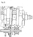
- Fig. 1 is a longitudinal sectional view showing a combustion engine E equipped with a supercharger drive device 1 designed in accordance with a first preferred embodiment of the present invention.
- the combustion engine E shown therein includes a crankshaft 2 which is a rotary shaft, a balancer shaft 4 disposed so as to extend parallel to the crankshaft 2, and a crankshaft gear 5 formed in an outer periphery of one of paired webs 3 of the crankshaft 2 for driving a balancer shaft 4.
- the gear carrier shaft 6 is provided with a high speed gear 8 and a low speed gear 10, each of which is a kind of a speed change gear. Both of the high speed gear 8 and the low speed gear 10 are speed increasing gears and are mounted on the gear carrier shaft 6 for rotation relative to, but axially immovably relative to such gear carrier shaft 6. It is to be noted that although in the illustrated embodiment, the two speed change gears, i.e., the high and low speed gears, are shown and described as employed, three or more speed change gears may be employed.
- the combustion engine E is equipped with a supercharger 12 for compressing and forcibly supplying air to the combustion engine E.
- This supercharger 12 includes a drive shaft 14 drivingly connected with one of the high and low speed gears 8 and 10, which have large and reduced diameters, respectively. More specifically, the supercharger drive shaft 14 has a low speed drive gear 14a of a reduced diameter and a high speed drive gear 14b of a large diameter, which are mounted on such drive shaft 14 for rotation together therewith. Those high speed gear 8, low speed gear 10, high speed drive gear 14a and low speed drive gear 14b cooperate with each other to define a speed increasing gear train.
- the drive shaft 14 and the gear carrier shaft 6 are connected directly with each other, but they may be connected indirectly with each other through, for example, an idle gear. While the details of the supercharger 12 will be described later, the drive shaft 14 is rotatably supported by an engine casing EC, which forms a part of an engine body, through three bearings 15.
- a gear shifter 16 is interposed between the high speed gear 8 and the low speed gear 10.
- This gear shifter 16 is made up of a shifting drum 17 having its opposite side faces formed with first and second dogs 17a and 17a each protruding the corresponding side face of the shifting drum 17 in a direction parallel to the axial direction of the gear carrier shaft 6, and a shifting fork 19 for operating the shifting drum 17.
- This shifting drum 17 is so splined to the gear carrier shaft 6 that the shifting drum 17 can be axially movable along the gear carrier shaft 6, but cannot rotate independently of the gear carrier shaft 6.
- the shifting fork 19 referred to above is driven by a shifter drive unit 18 in the axial direction of the gear carrier shaft 6 to move the shifting drum 17 in such axial direction so that the first and second dogs 17a and 17a rigid or integral with the shifting drum 17 can be selectively engaged in engagement holes 8a and 10a, which are defined in the high speed gear 8 and the low speed gear 10, to selectively interlock the shifting drum 17 with one of the high speed gear 8 and the low speed gear 10 one at a time.
- the shifter drive unit 18 is of a type including, for example, a servo motor, but may not be necessarily limited thereto.
- the supercharger 12 is disposed outside the engine casing EC forming a part of the engine body and, as shown in Fig. 2 in a sectional view thereof, one end 14c of the drive shaft 14 of the supercharger 12 is connected with one end 22a of an impeller shaft 22 through a planetary gear assembly 20 while an impeller 24 mounted on the opposite end 22b of the impeller shaft 22 for rotation together therewith.
- one end of the supercharger 12 is referred to as an engine E side and the opposite end thereof is referred to as a counter engine side.
- the impeller shaft 22 is rotatably supported by a tubular housing 26.
- the housing 26 has one end side fixed to the engine casing EC, forming a part of the combustion engine, through an anchoring casing 28 by means of housing fastening members 60 such as, for example, bolts and also has the opposite end side to which a casing 30 for enclosing the impeller 24 is fitted with the use of a plurality of casing fastening member 62 such as, for example, bolts.
- the anchoring casing 28 has a shaft support portion 28a supporting an input shaft 29 of the planetary gear assembly 20 through two bearings 31, and the drive shaft 14 referred to previously is relatively non-rotatably connected with the input shaft 29.
- the planetary gear assembly 20 is interposed between the drive shaft 14 and the impeller shaft 22 and is supported by one end portion of the housing 26.
- the supercharger 12 and the planetary gear assembly 20 are supported by the housing 26 to form a supercharger unit, which is in turn fitted to the engine casing EC, forming a part of the engine body, by means of the housing fastening members 60.
- An internal gear 32 of a large diameter is meshed with the input shaft 29 of the planetary gear assembly 20, a plurality of planetary gears 38 are meshed with this internal gear 32, and a gear 34 mounted on one end portion 22a of the impeller shaft 22 as a sun gear is meshed with those planetary gears 38. Accordingly, the rotational drive of the drive shaft 14 is transmitted from the input shaft 29 of the planetary gear assembly 20 to the impeller shaft 22, which serves as an output shaft, through the internal gear 32 and the planetary gears 38.
- the gear shifter 16 of the structure described above and shown in Fig. 1 operates in the following manner.
- a rotation sensor 40 for measuring the rotational speed of the combustion engine E and an hand operated switch SW for manually setting an operating mode of the combustion engine E are connected with an engine control unit ECU.
- the shifter drive unit 18 is operable to move the gear shifter 16 in a direction axially of the gear carrier shaft 6 in dependence on the rotational speed of the combustion engine E.
- the engine control unit ECU determines either a normal (low speed) mode 42 or a high speed mode 44 in reference to an increase of the rotational speed of the crankshaft 2, which is made available from the rotation sensor 40, and then control the shifter drive unit 18 so that the latter drives the gear shifter 16 to select one of the speed change gears 8 and 10, which is appropriate to one of the modes 42 and 44 which has been determined by the engine control unit ECU.
- the low speed mode 42 referred to above is a mode, under which the speed-up ratio of the supercharger 12 during a predetermined low speed region of the combustion engine E is increased to increase a supercharge pressure, that is, the amount of supercharged air so that the engine torque at the low speed can be gained.
- the gear shifter 16 is dogged with the high speed gear 8.
- the high speed mode 44 referred to above is a mode, under which the speed-up ratio of the supercharger 12 during a predetermined high speed region is reduced to prevent the amount of the supercharged air from being excessive so that a proper engine torque and a stabilized rotation can be obtained.
- the gear shifter 16 is dogged with the low speed gear 10.
- the engine control unit ECU controls the amount of fuel to be injected, the ignition timing and other parameters on the basis of a sensor signal, fed from the rotation sensor 40 and indicative of the rotational speed of the combustion engine E, to thereby control the rotational speed of the combustion engine E.
- the engine control unit ECU is also operable to increase the rotational speed of the supercharger 12 during the low speed mode 42 as hereinabove described, but to suppress the rotational speed of the supercharger 12 from becoming excessive on the basis of the sensor signal from the rotation sensor 40 during the high speed mode 44.
- the operating mode can be switched even with the hand operated switch SW. Accordingly, the operator can select one of the modes at his or her will.
- an eco mode 46 may be employed, during which the drive of the supercharger 12 is switched off. During the eco mode 46, the gear shifter 16 is held at an intermediate position at which the gear shifter 16 is engaged neither with the high speed gear 8 nor with the low speed gear 10.
- the shifter drive unit 18 shown in Fig. 1 actuates the gear shifter 16 in dependence on the rotational speed of the combustion engine E to select one of the speed change gears 8 and 10 and, accordingly, the rotational speed of the supercharger 12 can be adjusted to an optimum value in dependence on the rotational speed of the engine E.
- the gear shifter 16 is dogged with the high speed gear 8 to increase the speed-up ratio of the supercharger 12 so that control can be made to gain the engine torque during the medium-to-low speed region as shown in Fig. 4 .
- the shaft output of the combustion engine during the medium-to-low speed region also increases.
- the gear shifter 16 is dogged with the low speed gear 10 by the shifter drive unit 18 shown in Fig. 3 to reduce the speed-up ratio of the supercharger 12 so that control can be made to prevent the amount of the supercharged air during the high speed region from becoming excessive to thereby secure the proper engine torque and the stabilized revolution as shown in Fig. 4 .
- the high shaft output of the combustion engine during the high speed region is maintained.
- crankshaft gear 5 is concurrently used to drive the supercharger 12, an undesirable increase of the number of component parts can be suppressed.
- gear carrier shaft 6, the gear shifter 16 and other components can be arranged with the utilization of the dead space available on one side of the crankshaft 2 remote from the balancer shaft 4.
- the supercharger 12 and the planetary gear assembly 20 are unitized together to provide the supercharger unit, not only can the number of assembling steps be reduced while the undesirable increase of the number of component parts is avoided, but also a large speed-up can be obtained by the use of the planetary gear assembly 20 and, therefore, the supercharger drive device 1 can be downsized advantageously.
- the supercharger drive device now identified by 1A includes a gear carrier shaft 6A having the high speed gear 8 and the low speed gear 10 mounted thereon for rotation together therewith, and an electrically drive starter 50 is operatively coupled with the gear carrier shaft 6A through a one-way clutch 48 and a starter drum 49.
- the starter drum 49 is specifically mounted on an outer periphery of the gear carrier shaft 6A for rotation relative to such gear carrier shaft 6a, and has a starter gear 49a mounted on one end thereof for engagement with the electrically operated starter 50.
- the one-way clutch 48 referred to above is interposed between a cylindrical portion 49b of the other end of the starter drum 49, remote from the starter gear 49a, and a drive gear 7A that is formed integrally with the gear carrier shaft 6A.
- the one-way clutch 48 is brought into a coupled position to enable the transmission of the rotational force from the starter drum 49 to the drive gear 7A. Conversely, when the drive gear 7A attains a speed higher than that of the starter drum 49 subsequent to the start of the combustion engine, the one-way clutch 48 is brought into a decoupled position to interrupt the transmission of the rotational force from the drive gear 7A to the starter drum 49.
- the use may be made of a variable transmission for driving the supercharger 12 therethrough so that the speed-up ration can be changed in such a way as to increase the speed-up ratio at a low speed rotation but to reduce the speed-up ratio at a high speed rotation. Accordingly, a relatively high engine torque can be obtained from the low speed rotation and an undesirable occurrence of an excessive engine torque at the high speed rotation can be suppressed advantageously.
Claims (13)
- Un dispositif d'entraînement de compresseur d'alimentation pour un moteur à combustion, qui comprend :un arbre-pignon (6; 6A) exploitable pour tourner de concert avec un vilebrequin (2) du moteur à combustion (E) ;une pluralité de roues de changement de vitesse (8, 10) montées sur l'arbre-pignon (6 ; 6A) ;un arbre d'entraînement (14) d'un compresseur d'alimentation (12) raccordé directement ou indirectement aux roues de changement de vitesse (8, 10) pour une rotation ;un levier de vitesse (16) pour sélectionner l'une des multiples roues de changement de vitesse (8, 10) afin de transmettre une force motrice de l'arbre-pignon (6 ; 6A) à l'arbre d'entraînement (14) au moyen de cette roue sélectionnée parmi les roues de changement de vitesse (8, 10) ; etune unité d'entraînement de levier (18) pour actionner le levier de vitesse (16), caractérisée en ce quele compresseur d'alimentation (12) est entraîné par l'intermédiaire d'une roue de vilebrequin (5) formée dans une périphérie externe d'un voile (3) du vilebrequin (2).
- Le dispositif d'entraînement de compresseur d'alimentation pour le moteur à combustion tel que revendiqué dans la revendication 1, dans lequel chacune des roues de changement de vitesse (8, 10) est une roue de vitesse vers le haut et l'unité d'entraînement de levier (18) est exploitable pour actionner le levier de vitesse (16) afin de sélectionner l'une des multiples roues de changement de vitesse (8, 10) de telle sorte que le rapport de vitesse vers le haut devienne bas avec une augmentation de la vitesse de rotation du vilebrequin (2).
- Le dispositif d'entraînement de compresseur d'alimentation pour le moteur à combustion tel que revendiqué dans la revendication 2, dans lequel les multiples roues de changement de vitesse (8, 10) incluent une roue basse vitesse (10) et une roue grande vitesse (8), les roues basse et grande vitesse (8, 10) étant toutes les deux montées sur l'arbre-pignon (6 ; 6A) pour une rotation relativement à celui-ci ; et
dans lequel le levier de vitesse (16) est interposé entre la roue basse vitesse (10) et la roue grande vitesse (8) et monté sur l'arbre-pignon (6 ; 6A) pour un déplacement dans une direction axialement à l'arbre-pignon (6 ; 6A), mais ne pouvant pas tourner relativement à cet arbre-pignon (6 ; 6A), grâce à quoi lors d'un déplacement axial du levier de vitesse (16), celui-ci est sélectivement mis en prise avec une roue parmi la roue basse vitesse (10) et la roue grande vitesse (8) pour une rotation conjointement avec celle-ci. - Le dispositif d'entraînement de compresseur d'alimentation pour le moteur à combustion tel que revendiqué dans l'une quelconque des revendications 1 à 3, dans lequel l'arbre-pignon (6) est en engrenage avec une roue de vilebrequin (5) montée sur le vilebrequin (2) pour entraîner un arbre d'équilibrage (4).
- Le dispositif d'entraînement de compresseur d'alimentation pour le moteur à combustion tel que revendiqué dans l'une quelconque des revendications 1 à 3, dans lequel l'arbre-pignon (6A) est couplé à un démarreur (50) par le biais d'un embrayage unidirectionnel (48).
- Le dispositif d'entraînement de compresseur d'alimentation tel que revendiqué dans l'une quelconque des revendications 1 à 3, dans lequel le compresseur d'alimentation comprend
l'arbre d'entraînement (14),
un arbre d'impulseur (22) raccordé à l'arbre d'entraînement (14) par le biais d'un ensemble roue planétaire (20),
un impulseur (24) monté de manière fixe sur l'arbre d'impulseur (22),
un logement (26) pour supporter l'arbre d'impulseur (22), et
un carter (30) adapté sur le logement (26) pour renfermer l'impulseur (24), l'ensemble roue planétaire (20) étant supporté par le logement (26). - Le dispositif d'entraînement de compresseur d'alimentation pour le moteur à combustion tel que revendiqué dans la revendication 1, où l'arbre-pignon (6 ; 6A) a une roue d'entraînement (7) formée d'un seul tenant avec celui-ci et pouvant tourner de concert avec le vilebrequin (2) par le biais d'une mise en prise de l'arbre d'entraînement (14) avec la roue de vilebrequin (5).
- Le dispositif d'entraînement de compresseur d'alimentation pour le moteur à combustion tel que revendiqué dans la revendication 7, où la roue de vilebrequin (5) entraîne un arbre d'équilibrage (4).
- Le dispositif d'entraînement de compresseur d'alimentation pour le moteur à combustion tel que revendiqué dans la revendication 4, où l'arbre-pignon (6 ; 6A) est disposé sur un côté du vilebrequin (2) à distance de l'arbre équilibrage (4).
- Le dispositif d'entraînement de compresseur d'alimentation pour le moteur à combustion tel que revendiqué dans la revendication 1, comprenant en outre un ensemble roue planétaire (20) interposé entre l'arbre d'entraînement (14) et un arbre d'impulseur (22) du compresseur d'alimentation.
- Le dispositif d'entraînement de compresseur d'alimentation pour le moteur à combustion tel que revendiqué dans la revendication 3, où chacune des roues de changement de vitesse (8, 10) est une roue de vitesse vers le haut, et le levier de vitesse (16) est maintenu de manière sélective à une position intermédiaire à laquelle le levier de vitesse (16) n'est en prise ni avec la roue grande vitesse (8), ni avec la roue basse vitesse (10).
- Le dispositif d'entraînement de compresseur d'alimentation pour le moteur à combustion tel que revendiqué dans l'une quelconque des revendications 1 à 11, où :l'arbre d'entraînement (14) est supporté de manière à pouvoir tourner par un carter de moteur (EC), qui fait partie d'un corps de moteur du moteur à combustion (E) ; etle compresseur d'alimentation (12) est disposé à l'extérieur du carter de moteur (EC) et fixé au carter de moteur (EC).
- Le dispositif d'entraînement de compresseur d'alimentation pour le moteur à combustion tel que revendiqué dans la revendication 10, où :
le compresseur d'alimentation (12) et l'ensemble roue planétaire (20) sont unifiés pour former une unité de compresseur d'alimentation, et l'unité de compresseur d'alimentation est supportée par un carter de moteur (EC), qui fait partie d'un corps de moteur du moteur à combustion (E).
Applications Claiming Priority (2)
| Application Number | Priority Date | Filing Date | Title |
|---|---|---|---|
| JP2009236995 | 2009-10-14 | ||
| PCT/JP2010/067832 WO2011046096A1 (fr) | 2009-10-14 | 2010-10-12 | Dispositif d'entraînement de compresseur volumétrique de moteur |
Publications (3)
| Publication Number | Publication Date |
|---|---|
| EP2489854A1 EP2489854A1 (fr) | 2012-08-22 |
| EP2489854A4 EP2489854A4 (fr) | 2013-11-06 |
| EP2489854B1 true EP2489854B1 (fr) | 2019-04-17 |
Family
ID=43876146
Family Applications (1)
| Application Number | Title | Priority Date | Filing Date |
|---|---|---|---|
| EP10823364.4A Active EP2489854B1 (fr) | 2009-10-14 | 2010-10-12 | Dispositif d'entraînement de compresseur volumétrique de moteur |
Country Status (5)
| Country | Link |
|---|---|
| US (1) | US9127591B2 (fr) |
| EP (1) | EP2489854B1 (fr) |
| JP (2) | JP5882059B2 (fr) |
| CN (1) | CN102549250B (fr) |
| WO (1) | WO2011046096A1 (fr) |
Families Citing this family (18)
| Publication number | Priority date | Publication date | Assignee | Title |
|---|---|---|---|---|
| EP2584160A1 (fr) * | 2011-10-20 | 2013-04-24 | Alfa Laval Corporate AB | Séparateur de gaz de carter |
| JP6043353B2 (ja) * | 2012-07-11 | 2016-12-14 | 川崎重工業株式会社 | 鞍乗型車両のエンジン |
| EP2873833B1 (fr) * | 2012-07-11 | 2018-08-29 | Kawasaki Jukogyo Kabushiki Kaisha | Moteur ayant un compresseur d'alimentation |
| JP6074426B2 (ja) * | 2012-07-11 | 2017-02-01 | 川崎重工業株式会社 | エンジンの過給機取付構造 |
| CN102817710B (zh) * | 2012-09-04 | 2016-03-02 | 杭州闪鹿科技有限公司 | 离心式机械增压器 |
| WO2014041946A1 (fr) | 2012-09-13 | 2014-03-20 | 川崎重工業株式会社 | Moteur doté d'un compresseur |
| JP5964975B2 (ja) * | 2012-09-13 | 2016-08-03 | 川崎重工業株式会社 | 過給機付きエンジン |
| WO2014041945A1 (fr) * | 2012-09-13 | 2014-03-20 | 川崎重工業株式会社 | Moteur doté d'un compresseur |
| US9109502B1 (en) * | 2013-10-11 | 2015-08-18 | Accessible Technologies, Inc. | Control system for a supercharger with a variable transmission |
| EP3070288B1 (fr) | 2013-11-12 | 2020-02-26 | Kawasaki Jukogyo Kabushiki Kaisha | Compresseur de suralimentation pour un moteur |
| JP6216392B2 (ja) | 2013-11-12 | 2017-10-18 | 川崎重工業株式会社 | 動力伝達システムの潤滑構造 |
| CN105745417B (zh) | 2013-11-18 | 2018-11-02 | 川崎重工业株式会社 | 增压器的动力传递装置 |
| JP6437788B2 (ja) | 2013-11-18 | 2018-12-12 | 川崎重工業株式会社 | エンジンの過給機 |
| EP3239489B1 (fr) * | 2014-12-11 | 2021-08-11 | Kawasaki Jukogyo Kabushiki Kaisha | Turbine pour turbocompresseur |
| US9927006B2 (en) | 2015-09-01 | 2018-03-27 | Achates Power, Inc. | Multi-speed planetary drive for a supercharger |
| CN105370392B (zh) * | 2015-12-07 | 2018-05-29 | 中国南方航空工业(集团)有限公司 | 机械增压器 |
| CN106286745A (zh) * | 2016-08-16 | 2017-01-04 | 江苏三能动力总成有限公司 | 一种可变传动比机械增压器 |
| CN112459902B (zh) * | 2020-11-02 | 2022-03-22 | 邓云娣 | 一种机械传动结构、混合动力增压装置及发动机排气系统 |
Family Cites Families (37)
| Publication number | Priority date | Publication date | Assignee | Title |
|---|---|---|---|---|
| US1791393A (en) * | 1929-06-20 | 1931-02-03 | Armstrong Siddeley Motors Ltd | Gearing for superchargers used with internal-combustion engines |
| US1977553A (en) * | 1932-03-12 | 1934-10-16 | Halford Frank Bernard | Mechanism for driving the impeller of a supercharger for an internal combustion engine |
| US2080079A (en) * | 1933-11-04 | 1937-05-11 | Warren Macclatchie J | Supercharger |
| US2082556A (en) * | 1934-10-18 | 1937-06-01 | Edward J Smith | Supercharger drive |
| US2187737A (en) * | 1936-09-11 | 1940-01-23 | Ranger Engineering Corp | Variable speed supercharger drive |
| US2099675A (en) * | 1936-10-16 | 1937-11-23 | Armstrong Siddeley Motors Ltd | Gearing for driving superchargers on aircraft engines |
| US2139986A (en) * | 1937-07-28 | 1938-12-13 | Armstrong Siddeley Motors Ltd | Control of gearing for driving superchargers on aircraft engines |
| US2242374A (en) * | 1937-09-11 | 1941-05-20 | Messerschmitt Boelkow Blohm | Automatic control of two-speed gears in aircraft |
| US2197179A (en) * | 1939-02-03 | 1940-04-16 | United Aircraft Corp | Two-speed supercharger |
| US2263453A (en) * | 1940-06-07 | 1941-11-18 | Wright Aeronautical Corp | Two-speed supercharger drive |
| US2400830A (en) * | 1942-07-04 | 1946-05-21 | Continental Aviat & Engineerin | Engine |
| US2400307A (en) * | 1943-06-26 | 1946-05-14 | United Aircraft Corp | Variable-speed drive |
| US2406417A (en) * | 1944-08-30 | 1946-08-27 | Gandolph J Viviano | Two-speed drive for superchargers |
| JPS5720516A (en) * | 1980-07-12 | 1982-02-03 | Hino Motors Ltd | Diesel engine |
| JPS6136131U (ja) * | 1984-08-02 | 1986-03-06 | マツダ株式会社 | 過給機付エンジン |
| US5105793A (en) * | 1987-09-05 | 1992-04-21 | Zahnradfabrik Friedrichshafen, Ag. | Mechanical driving mechanism of a supercharger for an internal combustion engine |
| JP2632903B2 (ja) * | 1988-03-10 | 1997-07-23 | ヤマハ発動機株式会社 | 自動二輪車用エンジン |
| JPH026289A (ja) * | 1988-06-23 | 1990-01-10 | Yamaha Motor Co Ltd | 過給機付きエンジンを備えた自動二輪車 |
| JPH0216330A (ja) | 1988-06-30 | 1990-01-19 | Yamaha Motor Co Ltd | 過給機付きエンジンを備えた自動二輪車 |
| JPH0224284A (ja) | 1988-07-11 | 1990-01-26 | Yamaha Motor Co Ltd | 過給機付きエンジンを備えた自動二輪車 |
| JPH0270920A (ja) * | 1988-09-02 | 1990-03-09 | Yamaha Motor Co Ltd | 過給機付きエンジンを備えた自動二輪車 |
| JPH0315781A (ja) | 1989-06-14 | 1991-01-24 | Oki Electric Ind Co Ltd | 音響方位探知装置 |
| KR930700791A (ko) * | 1990-06-13 | 1993-03-16 | 라이문트 라우에·에델버트 발터어 | 구동 장치 |
| JPH0530433A (ja) | 1991-07-18 | 1993-02-05 | Hitachi Ltd | 撮像装置 |
| JP2574497Y2 (ja) | 1991-09-27 | 1998-06-11 | 愛知機械工業株式会社 | 機械式過給機 |
| JPH0586951A (ja) * | 1991-09-30 | 1993-04-06 | Mazda Motor Corp | エンジンを含む機械式過給機の制御装置 |
| JP3281100B2 (ja) * | 1993-03-29 | 2002-05-13 | 栃木富士産業株式会社 | 過給機 |
| JP2000230614A (ja) * | 1999-02-10 | 2000-08-22 | Tochigi Fuji Ind Co Ltd | 動力伝達機構およびこれを備えた過給機 |
| JP2001187913A (ja) * | 1999-12-28 | 2001-07-10 | Yamaha Motor Co Ltd | エンジンのクランク軸 |
| CA2368517A1 (fr) * | 2000-02-29 | 2001-09-07 | Bombardier-Rotax Gmbh | Moteur a quatre temps a systeme de ventilation de gaz de combustion et systeme de lubrification |
| JP2002005236A (ja) * | 2000-06-16 | 2002-01-09 | Honda Motor Co Ltd | 内燃機関のクランク軸 |
| US20020096156A1 (en) * | 2001-01-19 | 2002-07-25 | Joseph Palazzolo | Multi-speed gear arrangement for a centrifugal engine charger |
| DE102006028235A1 (de) * | 2006-06-20 | 2007-12-27 | Daimlerchrysler Ag | Turbocompound |
| CN200978709Y (zh) * | 2006-11-20 | 2007-11-21 | 广西壮族自治区汽车拖拉机研究所 | 单缸柴油机进气增压装置 |
| DE102008053383A1 (de) * | 2007-11-23 | 2009-05-28 | Luk Lamellen Und Kupplungsbau Beteiligungs Kg | Kompressorantriebsanordnung mit variabler Drehzahl |
| US8151772B2 (en) * | 2008-05-30 | 2012-04-10 | Brp-Powertrain Gmbh & Co. Kg | Supercharged engine |
| DE102009038736B3 (de) * | 2009-08-27 | 2011-01-13 | Voith Patent Gmbh | Turbine und Turboverdichter, insbesondere für ein Turbo-Compound-System |
-
2010
- 2010-10-12 CN CN201080045706.XA patent/CN102549250B/zh active Active
- 2010-10-12 JP JP2011536129A patent/JP5882059B2/ja active Active
- 2010-10-12 WO PCT/JP2010/067832 patent/WO2011046096A1/fr active Application Filing
- 2010-10-12 EP EP10823364.4A patent/EP2489854B1/fr active Active
-
2012
- 2012-04-06 US US13/441,737 patent/US9127591B2/en active Active
-
2013
- 2013-08-09 JP JP2013166231A patent/JP5882265B2/ja active Active
Non-Patent Citations (1)
| Title |
|---|
| None * |
Also Published As
| Publication number | Publication date |
|---|---|
| JPWO2011046096A1 (ja) | 2013-03-07 |
| US9127591B2 (en) | 2015-09-08 |
| EP2489854A4 (fr) | 2013-11-06 |
| JP5882265B2 (ja) | 2016-03-09 |
| JP2013224676A (ja) | 2013-10-31 |
| EP2489854A1 (fr) | 2012-08-22 |
| WO2011046096A1 (fr) | 2011-04-21 |
| CN102549250B (zh) | 2014-12-03 |
| US20120186565A1 (en) | 2012-07-26 |
| CN102549250A (zh) | 2012-07-04 |
| JP5882059B2 (ja) | 2016-03-09 |
Similar Documents
| Publication | Publication Date | Title |
|---|---|---|
| EP2489854B1 (fr) | Dispositif d'entraînement de compresseur volumétrique de moteur | |
| JP2013224676A5 (fr) | ||
| US8826878B2 (en) | Multiple gear ratio starter motor | |
| US9302576B2 (en) | Power transmitting apparatus for a hybrid vehicle | |
| KR200487107Y1 (ko) | 내연기관 및 시동 발전기를 포함하는 자동차용 구동 트레인 | |
| EP3009714B1 (fr) | Dispositif de commande de véhicule | |
| US8177671B2 (en) | Control system for hybrid drive unit | |
| US20090176611A1 (en) | Auxiliary Unit Drive for a motor vehicle | |
| US20100120569A1 (en) | Driving apparatus for hybrid vehicle | |
| JP4627425B2 (ja) | 無段変速機の変速制御装置 | |
| JP2003120765A (ja) | 可変速モータ・ジェネレータ | |
| CN104583562A (zh) | 用于附属驱动装置的受控张紧装置以及包括所述张紧装置的附属驱动装置 | |
| JP3291983B2 (ja) | 車両用駆動装置 | |
| WO2010067673A1 (fr) | Dispositif d’embrayage à roue libre à rouleaux, et démarreur et dispositif de démarrage de moteur utilisant tous les deux celui-ci | |
| CN100464092C (zh) | 具有可变带轮的传动装置 | |
| US20230009612A1 (en) | Saddle-ride type vehicle with hybrid propulsion | |
| JP3642418B2 (ja) | 往復動内燃機関およびその運転方法 | |
| US8910607B2 (en) | Method and mechanism configured for reducing powertrain rigid body motion during start/stop | |
| EP4065397B1 (fr) | Groupe motopropulseur pour un véhicule hybride doux et véhicule comprenant celui-ci | |
| WO2021255891A1 (fr) | Véhicule à selle à transmission manuelle | |
| US11027607B2 (en) | Drive system for an engine arrangement | |
| JPS6017554Y2 (ja) | 内燃機関のフライホイ−ル | |
| JPH0355813Y2 (fr) | ||
| WO2017171079A1 (fr) | Dispositif d'équilibrage pour moteur à combustion interne | |
| JPH05263874A (ja) | エンジンの可変フライホイール |
Legal Events
| Date | Code | Title | Description |
|---|---|---|---|
| PUAI | Public reference made under article 153(3) epc to a published international application that has entered the european phase |
Free format text: ORIGINAL CODE: 0009012 |
|
| 17P | Request for examination filed |
Effective date: 20120413 |
|
| AK | Designated contracting states |
Kind code of ref document: A1 Designated state(s): AL AT BE BG CH CY CZ DE DK EE ES FI FR GB GR HR HU IE IS IT LI LT LU LV MC MK MT NL NO PL PT RO RS SE SI SK SM TR |
|
| DAX | Request for extension of the european patent (deleted) | ||
| A4 | Supplementary search report drawn up and despatched |
Effective date: 20131004 |
|
| RIC1 | Information provided on ipc code assigned before grant |
Ipc: F02B 77/00 20060101ALI20130927BHEP Ipc: F02B 67/00 20060101ALI20130927BHEP Ipc: F02B 33/40 20060101ALI20130927BHEP Ipc: F02B 39/04 20060101AFI20130927BHEP Ipc: F02D 41/00 20060101ALI20130927BHEP Ipc: F02N 15/02 20060101ALI20130927BHEP Ipc: F02B 67/04 20060101ALI20130927BHEP |
|
| 17Q | First examination report despatched |
Effective date: 20161006 |
|
| STAA | Information on the status of an ep patent application or granted ep patent |
Free format text: STATUS: EXAMINATION IS IN PROGRESS |
|
| GRAP | Despatch of communication of intention to grant a patent |
Free format text: ORIGINAL CODE: EPIDOSNIGR1 |
|
| STAA | Information on the status of an ep patent application or granted ep patent |
Free format text: STATUS: GRANT OF PATENT IS INTENDED |
|
| INTG | Intention to grant announced |
Effective date: 20181130 |
|
| GRAS | Grant fee paid |
Free format text: ORIGINAL CODE: EPIDOSNIGR3 |
|
| GRAA | (expected) grant |
Free format text: ORIGINAL CODE: 0009210 |
|
| STAA | Information on the status of an ep patent application or granted ep patent |
Free format text: STATUS: THE PATENT HAS BEEN GRANTED |
|
| AK | Designated contracting states |
Kind code of ref document: B1 Designated state(s): AL AT BE BG CH CY CZ DE DK EE ES FI FR GB GR HR HU IE IS IT LI LT LU LV MC MK MT NL NO PL PT RO RS SE SI SK SM TR |
|
| REG | Reference to a national code |
Ref country code: GB Ref legal event code: FG4D |
|
| REG | Reference to a national code |
Ref country code: CH Ref legal event code: EP |
|
| REG | Reference to a national code |
Ref country code: DE Ref legal event code: R096 Ref document number: 602010058342 Country of ref document: DE |
|
| REG | Reference to a national code |
Ref country code: AT Ref legal event code: REF Ref document number: 1121797 Country of ref document: AT Kind code of ref document: T Effective date: 20190515 Ref country code: IE Ref legal event code: FG4D |
|
| REG | Reference to a national code |
Ref country code: NL Ref legal event code: MP Effective date: 20190417 |
|
| REG | Reference to a national code |
Ref country code: LT Ref legal event code: MG4D |
|
| PG25 | Lapsed in a contracting state [announced via postgrant information from national office to epo] |
Ref country code: NL Free format text: LAPSE BECAUSE OF FAILURE TO SUBMIT A TRANSLATION OF THE DESCRIPTION OR TO PAY THE FEE WITHIN THE PRESCRIBED TIME-LIMIT Effective date: 20190417 |
|
| PG25 | Lapsed in a contracting state [announced via postgrant information from national office to epo] |
Ref country code: NO Free format text: LAPSE BECAUSE OF FAILURE TO SUBMIT A TRANSLATION OF THE DESCRIPTION OR TO PAY THE FEE WITHIN THE PRESCRIBED TIME-LIMIT Effective date: 20190717 Ref country code: FI Free format text: LAPSE BECAUSE OF FAILURE TO SUBMIT A TRANSLATION OF THE DESCRIPTION OR TO PAY THE FEE WITHIN THE PRESCRIBED TIME-LIMIT Effective date: 20190417 Ref country code: PT Free format text: LAPSE BECAUSE OF FAILURE TO SUBMIT A TRANSLATION OF THE DESCRIPTION OR TO PAY THE FEE WITHIN THE PRESCRIBED TIME-LIMIT Effective date: 20190817 Ref country code: AL Free format text: LAPSE BECAUSE OF FAILURE TO SUBMIT A TRANSLATION OF THE DESCRIPTION OR TO PAY THE FEE WITHIN THE PRESCRIBED TIME-LIMIT Effective date: 20190417 Ref country code: HR Free format text: LAPSE BECAUSE OF FAILURE TO SUBMIT A TRANSLATION OF THE DESCRIPTION OR TO PAY THE FEE WITHIN THE PRESCRIBED TIME-LIMIT Effective date: 20190417 Ref country code: SE Free format text: LAPSE BECAUSE OF FAILURE TO SUBMIT A TRANSLATION OF THE DESCRIPTION OR TO PAY THE FEE WITHIN THE PRESCRIBED TIME-LIMIT Effective date: 20190417 Ref country code: LT Free format text: LAPSE BECAUSE OF FAILURE TO SUBMIT A TRANSLATION OF THE DESCRIPTION OR TO PAY THE FEE WITHIN THE PRESCRIBED TIME-LIMIT Effective date: 20190417 Ref country code: ES Free format text: LAPSE BECAUSE OF FAILURE TO SUBMIT A TRANSLATION OF THE DESCRIPTION OR TO PAY THE FEE WITHIN THE PRESCRIBED TIME-LIMIT Effective date: 20190417 |
|
| PG25 | Lapsed in a contracting state [announced via postgrant information from national office to epo] |
Ref country code: GR Free format text: LAPSE BECAUSE OF FAILURE TO SUBMIT A TRANSLATION OF THE DESCRIPTION OR TO PAY THE FEE WITHIN THE PRESCRIBED TIME-LIMIT Effective date: 20190718 Ref country code: BG Free format text: LAPSE BECAUSE OF FAILURE TO SUBMIT A TRANSLATION OF THE DESCRIPTION OR TO PAY THE FEE WITHIN THE PRESCRIBED TIME-LIMIT Effective date: 20190717 Ref country code: RS Free format text: LAPSE BECAUSE OF FAILURE TO SUBMIT A TRANSLATION OF THE DESCRIPTION OR TO PAY THE FEE WITHIN THE PRESCRIBED TIME-LIMIT Effective date: 20190417 Ref country code: PL Free format text: LAPSE BECAUSE OF FAILURE TO SUBMIT A TRANSLATION OF THE DESCRIPTION OR TO PAY THE FEE WITHIN THE PRESCRIBED TIME-LIMIT Effective date: 20190417 Ref country code: LV Free format text: LAPSE BECAUSE OF FAILURE TO SUBMIT A TRANSLATION OF THE DESCRIPTION OR TO PAY THE FEE WITHIN THE PRESCRIBED TIME-LIMIT Effective date: 20190417 |
|
| REG | Reference to a national code |
Ref country code: AT Ref legal event code: MK05 Ref document number: 1121797 Country of ref document: AT Kind code of ref document: T Effective date: 20190417 |
|
| PG25 | Lapsed in a contracting state [announced via postgrant information from national office to epo] |
Ref country code: IS Free format text: LAPSE BECAUSE OF FAILURE TO SUBMIT A TRANSLATION OF THE DESCRIPTION OR TO PAY THE FEE WITHIN THE PRESCRIBED TIME-LIMIT Effective date: 20190817 |
|
| REG | Reference to a national code |
Ref country code: DE Ref legal event code: R097 Ref document number: 602010058342 Country of ref document: DE |
|
| PG25 | Lapsed in a contracting state [announced via postgrant information from national office to epo] |
Ref country code: CZ Free format text: LAPSE BECAUSE OF FAILURE TO SUBMIT A TRANSLATION OF THE DESCRIPTION OR TO PAY THE FEE WITHIN THE PRESCRIBED TIME-LIMIT Effective date: 20190417 Ref country code: RO Free format text: LAPSE BECAUSE OF FAILURE TO SUBMIT A TRANSLATION OF THE DESCRIPTION OR TO PAY THE FEE WITHIN THE PRESCRIBED TIME-LIMIT Effective date: 20190417 Ref country code: AT Free format text: LAPSE BECAUSE OF FAILURE TO SUBMIT A TRANSLATION OF THE DESCRIPTION OR TO PAY THE FEE WITHIN THE PRESCRIBED TIME-LIMIT Effective date: 20190417 Ref country code: EE Free format text: LAPSE BECAUSE OF FAILURE TO SUBMIT A TRANSLATION OF THE DESCRIPTION OR TO PAY THE FEE WITHIN THE PRESCRIBED TIME-LIMIT Effective date: 20190417 Ref country code: DK Free format text: LAPSE BECAUSE OF FAILURE TO SUBMIT A TRANSLATION OF THE DESCRIPTION OR TO PAY THE FEE WITHIN THE PRESCRIBED TIME-LIMIT Effective date: 20190417 Ref country code: SK Free format text: LAPSE BECAUSE OF FAILURE TO SUBMIT A TRANSLATION OF THE DESCRIPTION OR TO PAY THE FEE WITHIN THE PRESCRIBED TIME-LIMIT Effective date: 20190417 |
|
| PLBE | No opposition filed within time limit |
Free format text: ORIGINAL CODE: 0009261 |
|
| STAA | Information on the status of an ep patent application or granted ep patent |
Free format text: STATUS: NO OPPOSITION FILED WITHIN TIME LIMIT |
|
| PG25 | Lapsed in a contracting state [announced via postgrant information from national office to epo] |
Ref country code: IT Free format text: LAPSE BECAUSE OF FAILURE TO SUBMIT A TRANSLATION OF THE DESCRIPTION OR TO PAY THE FEE WITHIN THE PRESCRIBED TIME-LIMIT Effective date: 20190417 Ref country code: SM Free format text: LAPSE BECAUSE OF FAILURE TO SUBMIT A TRANSLATION OF THE DESCRIPTION OR TO PAY THE FEE WITHIN THE PRESCRIBED TIME-LIMIT Effective date: 20190417 |
|
| 26N | No opposition filed |
Effective date: 20200120 |
|
| PG25 | Lapsed in a contracting state [announced via postgrant information from national office to epo] |
Ref country code: TR Free format text: LAPSE BECAUSE OF FAILURE TO SUBMIT A TRANSLATION OF THE DESCRIPTION OR TO PAY THE FEE WITHIN THE PRESCRIBED TIME-LIMIT Effective date: 20190417 |
|
| PG25 | Lapsed in a contracting state [announced via postgrant information from national office to epo] |
Ref country code: MC Free format text: LAPSE BECAUSE OF FAILURE TO SUBMIT A TRANSLATION OF THE DESCRIPTION OR TO PAY THE FEE WITHIN THE PRESCRIBED TIME-LIMIT Effective date: 20190417 Ref country code: SI Free format text: LAPSE BECAUSE OF FAILURE TO SUBMIT A TRANSLATION OF THE DESCRIPTION OR TO PAY THE FEE WITHIN THE PRESCRIBED TIME-LIMIT Effective date: 20190417 |
|
| REG | Reference to a national code |
Ref country code: CH Ref legal event code: PL |
|
| PG25 | Lapsed in a contracting state [announced via postgrant information from national office to epo] |
Ref country code: CH Free format text: LAPSE BECAUSE OF NON-PAYMENT OF DUE FEES Effective date: 20191031 Ref country code: LU Free format text: LAPSE BECAUSE OF NON-PAYMENT OF DUE FEES Effective date: 20191012 Ref country code: LI Free format text: LAPSE BECAUSE OF NON-PAYMENT OF DUE FEES Effective date: 20191031 |
|
| REG | Reference to a national code |
Ref country code: BE Ref legal event code: MM Effective date: 20191031 |
|
| PG25 | Lapsed in a contracting state [announced via postgrant information from national office to epo] |
Ref country code: BE Free format text: LAPSE BECAUSE OF NON-PAYMENT OF DUE FEES Effective date: 20191031 |
|
| GBPC | Gb: european patent ceased through non-payment of renewal fee |
Effective date: 20191012 |
|
| PG25 | Lapsed in a contracting state [announced via postgrant information from national office to epo] |
Ref country code: IE Free format text: LAPSE BECAUSE OF NON-PAYMENT OF DUE FEES Effective date: 20191012 Ref country code: GB Free format text: LAPSE BECAUSE OF NON-PAYMENT OF DUE FEES Effective date: 20191012 |
|
| PGFP | Annual fee paid to national office [announced via postgrant information from national office to epo] |
Ref country code: FR Payment date: 20200914 Year of fee payment: 11 |
|
| PG25 | Lapsed in a contracting state [announced via postgrant information from national office to epo] |
Ref country code: CY Free format text: LAPSE BECAUSE OF FAILURE TO SUBMIT A TRANSLATION OF THE DESCRIPTION OR TO PAY THE FEE WITHIN THE PRESCRIBED TIME-LIMIT Effective date: 20190417 |
|
| PG25 | Lapsed in a contracting state [announced via postgrant information from national office to epo] |
Ref country code: MT Free format text: LAPSE BECAUSE OF FAILURE TO SUBMIT A TRANSLATION OF THE DESCRIPTION OR TO PAY THE FEE WITHIN THE PRESCRIBED TIME-LIMIT Effective date: 20190417 Ref country code: HU Free format text: LAPSE BECAUSE OF FAILURE TO SUBMIT A TRANSLATION OF THE DESCRIPTION OR TO PAY THE FEE WITHIN THE PRESCRIBED TIME-LIMIT; INVALID AB INITIO Effective date: 20101012 |
|
| REG | Reference to a national code |
Ref country code: DE Ref legal event code: R081 Ref document number: 602010058342 Country of ref document: DE Owner name: KAWASAKI MOTORS, LTD., AKASHI-SHI, JP Free format text: FORMER OWNER: KAWASAKI JUKOGYO KABUSHIKI KAISHA, KOBE-SHI, HYOGO, JP |
|
| PG25 | Lapsed in a contracting state [announced via postgrant information from national office to epo] |
Ref country code: MK Free format text: LAPSE BECAUSE OF FAILURE TO SUBMIT A TRANSLATION OF THE DESCRIPTION OR TO PAY THE FEE WITHIN THE PRESCRIBED TIME-LIMIT Effective date: 20190417 |
|
| PG25 | Lapsed in a contracting state [announced via postgrant information from national office to epo] |
Ref country code: FR Free format text: LAPSE BECAUSE OF NON-PAYMENT OF DUE FEES Effective date: 20211031 |
|
| PGFP | Annual fee paid to national office [announced via postgrant information from national office to epo] |
Ref country code: DE Payment date: 20230830 Year of fee payment: 14 |