EP2489854B1 - Engine supercharger drive device - Google Patents
Engine supercharger drive device Download PDFInfo
- Publication number
- EP2489854B1 EP2489854B1 EP10823364.4A EP10823364A EP2489854B1 EP 2489854 B1 EP2489854 B1 EP 2489854B1 EP 10823364 A EP10823364 A EP 10823364A EP 2489854 B1 EP2489854 B1 EP 2489854B1
- Authority
- EP
- European Patent Office
- Prior art keywords
- gear
- supercharger
- shaft
- combustion engine
- speed
- Prior art date
- Legal status (The legal status is an assumption and is not a legal conclusion. Google has not performed a legal analysis and makes no representation as to the accuracy of the status listed.)
- Active
Links
- 238000002485 combustion reaction Methods 0.000 claims description 44
- 239000007858 starting material Substances 0.000 claims description 15
- 230000005540 biological transmission Effects 0.000 description 8
- 241000282472 Canis lupus familiaris Species 0.000 description 2
- 238000004873 anchoring Methods 0.000 description 2
- 238000010586 diagram Methods 0.000 description 2
- 238000010276 construction Methods 0.000 description 1
- 230000001419 dependent effect Effects 0.000 description 1
- 239000000446 fuel Substances 0.000 description 1
- 230000004048 modification Effects 0.000 description 1
- 238000012986 modification Methods 0.000 description 1
Images


Classifications
-
- F—MECHANICAL ENGINEERING; LIGHTING; HEATING; WEAPONS; BLASTING
- F02—COMBUSTION ENGINES; HOT-GAS OR COMBUSTION-PRODUCT ENGINE PLANTS
- F02B—INTERNAL-COMBUSTION PISTON ENGINES; COMBUSTION ENGINES IN GENERAL
- F02B33/00—Engines characterised by provision of pumps for charging or scavenging
- F02B33/32—Engines with pumps other than of reciprocating-piston type
- F02B33/34—Engines with pumps other than of reciprocating-piston type with rotary pumps
- F02B33/40—Engines with pumps other than of reciprocating-piston type with rotary pumps of non-positive-displacement type
-
- F—MECHANICAL ENGINEERING; LIGHTING; HEATING; WEAPONS; BLASTING
- F02—COMBUSTION ENGINES; HOT-GAS OR COMBUSTION-PRODUCT ENGINE PLANTS
- F02B—INTERNAL-COMBUSTION PISTON ENGINES; COMBUSTION ENGINES IN GENERAL
- F02B39/00—Component parts, details, or accessories relating to, driven charging or scavenging pumps, not provided for in groups F02B33/00 - F02B37/00
- F02B39/02—Drives of pumps; Varying pump drive gear ratio
- F02B39/04—Mechanical drives; Variable-gear-ratio drives
-
- F—MECHANICAL ENGINEERING; LIGHTING; HEATING; WEAPONS; BLASTING
- F02—COMBUSTION ENGINES; HOT-GAS OR COMBUSTION-PRODUCT ENGINE PLANTS
- F02D—CONTROLLING COMBUSTION ENGINES
- F02D2200/00—Input parameters for engine control
- F02D2200/02—Input parameters for engine control the parameters being related to the engine
- F02D2200/10—Parameters related to the engine output, e.g. engine torque or engine speed
- F02D2200/101—Engine speed
-
- F—MECHANICAL ENGINEERING; LIGHTING; HEATING; WEAPONS; BLASTING
- F02—COMBUSTION ENGINES; HOT-GAS OR COMBUSTION-PRODUCT ENGINE PLANTS
- F02D—CONTROLLING COMBUSTION ENGINES
- F02D41/00—Electrical control of supply of combustible mixture or its constituents
- F02D41/0002—Controlling intake air
- F02D41/0007—Controlling intake air for control of turbo-charged or super-charged engines
Landscapes
- Engineering & Computer Science (AREA)
- Chemical & Material Sciences (AREA)
- Combustion & Propulsion (AREA)
- Mechanical Engineering (AREA)
- General Engineering & Computer Science (AREA)
- Supercharger (AREA)
Description
- This application is based on and claims Convention priority to Japanese patent application No.
2009-236995, filed October 14, 2009 - The present invention relates to a supercharger drive device for variable transmission of a supercharger driven by a combustion engine.
- The supercharger connected with and driven by the combustion engine has such a tendency that if it is adjusted to be suitable for a low-to-medium speed region, the supercharged pressure (the amount of charged air) in a high speed region will increase too much, but if it is adjusted to be suitable for the high speed region the supercharged pressure in the low-to-medium speed region will become insufficient. The patent document listed below discloses the drive device operable to switch the supercharger, which is operatively linked with a transmission connected with the combustion engine, on or off in dependence of a gear shifting of the transmission. The drive device disclosed in the patent document has, however, been found having such a problem that the change gear ratio of the supercharger itself remains constant and is therefore insufficient.
- Document
US 2 197 179 A discloses a two speed supercharger having a supercharger drive according to the preamble ofclaim 1. - [Patent Document] JP Laid-open Utility Model Publication No.
H5-30433 - The present invention has been devised to substantially eliminate the foregoing problems and inconveniences inherent in the prior art and is intended to provide a supercharger drive device of a type, in which a change gear ratio of the supercharger can be selected in dependence on the number of revolutions, or rotational speed, of the combustion engine.
- In order to accomplish the foregoing object of the present invention, there is provided a supercharger drive device for a combustion engine designed in accordance with the present invention includes a gear carrier shaft operable to rotate in unison with a rotary shaft of the combustion engine, a plurality of speed change gears mounted on the gear carrier shaft, a drive shaft of a supercharger connected directly or indirectly with the speed change gears for rotation, a gear shifter for selecting one of the plural speed change gears to transmit a motive force from the gear carrier shaft to the drive shaft by way of such selected one of the speed change gears, and a shifter drive unit for actuating the gear shifter in dependence on the rotational speed of the combustion engine.
- According to the construction, the shifter drive unit selects one of the speed change gears by actuating the gear shifter in dependence on the rotational speed or the number of revolutions of the combustion engine and, therefore, the rotational speed of the supercharger can be adjusted to an optimum value in dependence on the rotational speed of the combustion engine.
- In a preferred embodiment of the present invention, each of the speed change gears may be a speed-up gear, in which case the shifter drive unit is preferably operable to actuate the gear shifter to select one of the plural speed change gears such that the speed-up ratio becomes low with an increase of the rotational speed of the rotary shaft. This structure makes it possible to provide the optimum speed-up ratio dependent on the rotational speed of the combustion engine.
- In another preferred embodiment of the present invention, the plural speed change gears may include a low speed gear and a high speed gear, both of the low and high speed gears being mounted on the gear carrier shaft for rotation relative to the latter, in which case the gear shifter is interposed between the low speed gear and the high speed gear and mounted on the gear carrier shaft for movement in a direction axially of the gear carrier shaft, but relatively non-rotatable to such gear carrier shaft, whereby upon axial movement of the gear shifter, the latter is selectively engaged with one of the low speed gear and the high speed gear for rotation together therewith.
- In a further preferred embodiment of the present invention, the gear carrier shaft may be engaged with a crankshaft gear mounted on the rotary shaft for driving a balancer shaft. According to this structure, the crankshaft gear is concurrently used to drive the supercharger and therefore, an undesirable increase of the number of component parts can be suppressed. Also, the gear carrier shaft, the gear shifter and other components can be arranged with the utilization of the dead space available on one side of the crankshaft remote from the balancer shaft.
- In a still further preferred embodiment of the present invention, the gear carrier shaft may be coupled with a starter through a one-way clutch. According to this structure, a change in engine torque incident to gear shifting can be absorbed by a slide friction taking place in the one-way clutch and therefore, it is possible to avoid a transmission thereof to the supercharger.
- In a yet still further preferred embodiment of the present invention, the supercharger may include the drive shaft, an impeller shaft connected with the drive shaft through a planetary gear assembly, an impeller fixedly mounted on the impeller shaft, a housing for supporting the impeller shaft, and a casing fitted to the housing for enclosing the impeller, the planetary gear assembly being supported by the housing. According to this structure, the supercharger and the planetary gear assembly can be unitized together as a single unit and, therefore, an undesirable increase of assembling steps can be suppressed while an undesirable increase of the number of component parts is also suppressed. Also, since a relatively large speed-up can be obtained due to the use of the planetary gear assembly, a speed increasing machine can be compactized.
- In any event, the present invention will become more clearly understood from the following description of preferred embodiments thereof, when taken in conjunction with the accompanying drawings. However, the embodiments and the drawings are given only for the purpose of illustration and explanation, and are not to be taken as limiting the scope of the present invention in any way whatsoever, which scope is to be determined by the appended claims. In the accompanying drawings, like reference numerals are used to denote like parts throughout the several views, and:
-
Fig. 1 is a longitudinal sectional view showing a combustion engine equipped with a supercharger drive device designed in accordance with a first preferred embodiment of the present invention; -
Fig. 2 is a longitudinal sectional view showing a supercharger driven by the supercharger drive device shown inFig. 1 ; -
Fig. 3 is a block diagram showing an operative linkage system of various component parts of the supercharger drive device; -
Fig. 4 is a chart showing characteristics of the supercharger drive device; and -
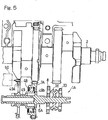
Fig. 5 is a sectional diagram showing a gear carrier shaft employed in the supercharger drive device designed in accordance with a second preferred embodiment of the present invention. - Hereinafter, the present invention will be described in detail in connection with preferred embodiments thereof with reference to the accompanying drawings.
-
Fig. 1 is a longitudinal sectional view showing a combustion engine E equipped with asupercharger drive device 1 designed in accordance with a first preferred embodiment of the present invention. The combustion engine E shown therein includes acrankshaft 2 which is a rotary shaft, a balancer shaft 4 disposed so as to extend parallel to thecrankshaft 2, and a crankshaft gear 5 formed in an outer periphery of one of paired webs 3 of thecrankshaft 2 for driving a balancer shaft 4. Agear carrier shaft 6, which is one kind of an idle shaft, is disposed on one side of thecrankshaft 2 remote from the balancer shaft 4, whichshaft 6 is rotatable in unison with thecrankshaft 2 through an engagement of a drive gear 7, formed integrally with thegear carrier shaft 6, with the crankshaft gear 5. - The
gear carrier shaft 6 is provided with ahigh speed gear 8 and alow speed gear 10, each of which is a kind of a speed change gear. Both of thehigh speed gear 8 and thelow speed gear 10 are speed increasing gears and are mounted on thegear carrier shaft 6 for rotation relative to, but axially immovably relative to suchgear carrier shaft 6. It is to be noted that although in the illustrated embodiment, the two speed change gears, i.e., the high and low speed gears, are shown and described as employed, three or more speed change gears may be employed. - The combustion engine E is equipped with a
supercharger 12 for compressing and forcibly supplying air to the combustion engine E. Thissupercharger 12 includes adrive shaft 14 drivingly connected with one of the high andlow speed gears supercharger drive shaft 14 has a lowspeed drive gear 14a of a reduced diameter and a highspeed drive gear 14b of a large diameter, which are mounted onsuch drive shaft 14 for rotation together therewith. Thosehigh speed gear 8,low speed gear 10, highspeed drive gear 14a and lowspeed drive gear 14b cooperate with each other to define a speed increasing gear train. In the embodiment now under discussion, thedrive shaft 14 and thegear carrier shaft 6 are connected directly with each other, but they may be connected indirectly with each other through, for example, an idle gear. While the details of thesupercharger 12 will be described later, thedrive shaft 14 is rotatably supported by an engine casing EC, which forms a part of an engine body, through threebearings 15. - A
gear shifter 16 is interposed between thehigh speed gear 8 and thelow speed gear 10. Thisgear shifter 16 is made up of a shiftingdrum 17 having its opposite side faces formed with first andsecond dogs drum 17 in a direction parallel to the axial direction of thegear carrier shaft 6, and a shifting fork 19 for operating the shiftingdrum 17. This shiftingdrum 17 is so splined to thegear carrier shaft 6 that the shiftingdrum 17 can be axially movable along thegear carrier shaft 6, but cannot rotate independently of thegear carrier shaft 6. The shifting fork 19 referred to above is driven by ashifter drive unit 18 in the axial direction of thegear carrier shaft 6 to move the shiftingdrum 17 in such axial direction so that the first andsecond dogs drum 17 can be selectively engaged inengagement holes high speed gear 8 and thelow speed gear 10, to selectively interlock the shiftingdrum 17 with one of thehigh speed gear 8 and thelow speed gear 10 one at a time. - Through the selected one of the
speed change gears gear carrier shaft 6 is transmitted to thedrive shaft 14. In other words, when the shiftingdrum 17 and thehigh speed gear 8 are dogged together in the manner described above, the rotation of thegear carrier shaft 6, that is, the rotation of thecrankshaft 2 is transmitted to thedrive shaft 14 at a large speed-up ratio, but when the shiftingdrum 17 and thelow speed gear 10 are dogged together, the rotation of thegear carrier shaft 6 is transmitted to thedrive shaft 14 at a small speed-up ratio. Theshifter drive unit 18 is of a type including, for example, a servo motor, but may not be necessarily limited thereto. By thisshifter drive unit 18, the rotational drive of thecrankshaft 2 is transmitted from thegear carrier shaft 6 to thedrive shaft 14 of thesupercharger 12 through the selectedspeed change gear gear carrier shaft 6,high speed gear 8,low speed gear 10,drive shaft 14 of thesupercharger 12,gear shifter 16 andshifter drive unit 18 altogether constitute thesupercharger drive device 1 of the kind referred to previously. - The
supercharger 12 is disposed outside the engine casing EC forming a part of the engine body and, as shown inFig. 2 in a sectional view thereof, oneend 14c of thedrive shaft 14 of thesupercharger 12 is connected with oneend 22a of animpeller shaft 22 through aplanetary gear assembly 20 while animpeller 24 mounted on theopposite end 22b of theimpeller shaft 22 for rotation together therewith. Hereinafter, one end of thesupercharger 12 is referred to as an engine E side and the opposite end thereof is referred to as a counter engine side. - The
impeller shaft 22 is rotatably supported by atubular housing 26. Thehousing 26 has one end side fixed to the engine casing EC, forming a part of the combustion engine, through ananchoring casing 28 by means of housing fasteningmembers 60 such as, for example, bolts and also has the opposite end side to which acasing 30 for enclosing theimpeller 24 is fitted with the use of a plurality of casing fastening member 62 such as, for example, bolts. In this way, a portion of theimpeller shaft 22, except for that end thereof where theimpeller 24 is mounted, is enclosed by thehousing 26 and that portion thereof, where theimpeller 24 is mounted, and theimpeller 24 itself are enclosed by thecasing 30. Theanchoring casing 28 has a shaft support portion 28a supporting aninput shaft 29 of theplanetary gear assembly 20 through twobearings 31, and thedrive shaft 14 referred to previously is relatively non-rotatably connected with theinput shaft 29. - As hereinabove described, the
planetary gear assembly 20 is interposed between thedrive shaft 14 and theimpeller shaft 22 and is supported by one end portion of thehousing 26. In the embodiment shown and now under discussion, thesupercharger 12 and theplanetary gear assembly 20 are supported by thehousing 26 to form a supercharger unit, which is in turn fitted to the engine casing EC, forming a part of the engine body, by means of thehousing fastening members 60. - An
internal gear 32 of a large diameter is meshed with theinput shaft 29 of theplanetary gear assembly 20, a plurality ofplanetary gears 38 are meshed with thisinternal gear 32, and agear 34 mounted on oneend portion 22a of theimpeller shaft 22 as a sun gear is meshed with thoseplanetary gears 38. Accordingly, the rotational drive of thedrive shaft 14 is transmitted from theinput shaft 29 of theplanetary gear assembly 20 to theimpeller shaft 22, which serves as an output shaft, through theinternal gear 32 and the planetary gears 38. - The
gear shifter 16 of the structure described above and shown inFig. 1 operates in the following manner. As best shown inFig. 3 , arotation sensor 40 for measuring the rotational speed of the combustion engine E and an hand operated switch SW for manually setting an operating mode of the combustion engine E are connected with an engine control unit ECU. Theshifter drive unit 18 is operable to move thegear shifter 16 in a direction axially of thegear carrier shaft 6 in dependence on the rotational speed of the combustion engine E. More specifically, the engine control unit ECU determines either a normal (low speed)mode 42 or ahigh speed mode 44 in reference to an increase of the rotational speed of thecrankshaft 2, which is made available from therotation sensor 40, and then control theshifter drive unit 18 so that the latter drives thegear shifter 16 to select one of the speed change gears 8 and 10, which is appropriate to one of themodes - The
low speed mode 42 referred to above is a mode, under which the speed-up ratio of thesupercharger 12 during a predetermined low speed region of the combustion engine E is increased to increase a supercharge pressure, that is, the amount of supercharged air so that the engine torque at the low speed can be gained. Once the engine control unit ECU determines thelow speed mode 42, thegear shifter 16 is dogged with thehigh speed gear 8. On the other hand, thehigh speed mode 44 referred to above is a mode, under which the speed-up ratio of thesupercharger 12 during a predetermined high speed region is reduced to prevent the amount of the supercharged air from being excessive so that a proper engine torque and a stabilized rotation can be obtained. Once the engine control unit ECU determines thehigh speed mode 44, thegear shifter 16 is dogged with thelow speed gear 10. - The engine control unit ECU controls the amount of fuel to be injected, the ignition timing and other parameters on the basis of a sensor signal, fed from the
rotation sensor 40 and indicative of the rotational speed of the combustion engine E, to thereby control the rotational speed of the combustion engine E. The engine control unit ECU is also operable to increase the rotational speed of thesupercharger 12 during thelow speed mode 42 as hereinabove described, but to suppress the rotational speed of thesupercharger 12 from becoming excessive on the basis of the sensor signal from therotation sensor 40 during thehigh speed mode 44. - In addition to the determination of the operating mode in dependence on the rotational speed of the combustion engine E as hereinabove described, the operating mode can be switched even with the hand operated switch SW. Accordingly, the operator can select one of the modes at his or her will. Also, an
eco mode 46 may be employed, during which the drive of thesupercharger 12 is switched off. During theeco mode 46, thegear shifter 16 is held at an intermediate position at which thegear shifter 16 is engaged neither with thehigh speed gear 8 nor with thelow speed gear 10. - According to the embodiment, the
shifter drive unit 18 shown inFig. 1 actuates thegear shifter 16 in dependence on the rotational speed of the combustion engine E to select one of the speed change gears 8 and 10 and, accordingly, the rotational speed of thesupercharger 12 can be adjusted to an optimum value in dependence on the rotational speed of the engine E. In other words, during thelow speed mode 42, thegear shifter 16 is dogged with thehigh speed gear 8 to increase the speed-up ratio of thesupercharger 12 so that control can be made to gain the engine torque during the medium-to-low speed region as shown inFig. 4 . As a result, the shaft output of the combustion engine during the medium-to-low speed region also increases. - On the other hand, during the
high speed mode 44, thegear shifter 16 is dogged with thelow speed gear 10 by theshifter drive unit 18 shown inFig. 3 to reduce the speed-up ratio of thesupercharger 12 so that control can be made to prevent the amount of the supercharged air during the high speed region from becoming excessive to thereby secure the proper engine torque and the stabilized revolution as shown inFig. 4 . As a result, the high shaft output of the combustion engine during the high speed region is maintained. - Also, since the crankshaft gear 5 is concurrently used to drive the
supercharger 12, an undesirable increase of the number of component parts can be suppressed. In addition, thegear carrier shaft 6, thegear shifter 16 and other components can be arranged with the utilization of the dead space available on one side of thecrankshaft 2 remote from the balancer shaft 4. - Yet, since the
supercharger 12 and theplanetary gear assembly 20 are unitized together to provide the supercharger unit, not only can the number of assembling steps be reduced while the undesirable increase of the number of component parts is avoided, but also a large speed-up can be obtained by the use of theplanetary gear assembly 20 and, therefore, thesupercharger drive device 1 can be downsized advantageously. - In a second preferred embodiment of the present invention, which will now be described with particular reference to
Fig. 5 showing a longitudinal sectional view, the supercharger drive device now identified by 1A according to this second embodiment includes agear carrier shaft 6A having thehigh speed gear 8 and thelow speed gear 10 mounted thereon for rotation together therewith, and an electrically drive starter 50 is operatively coupled with thegear carrier shaft 6A through a one-way clutch 48 and astarter drum 49. Thestarter drum 49 is specifically mounted on an outer periphery of thegear carrier shaft 6A for rotation relative to such gear carrier shaft 6a, and has a starter gear 49a mounted on one end thereof for engagement with the electrically operated starter 50. The one-way clutch 48 referred to above is interposed between acylindrical portion 49b of the other end of thestarter drum 49, remote from the starter gear 49a, and adrive gear 7A that is formed integrally with thegear carrier shaft 6A. - According to the second preferred embodiment, only when the
starter drum 49 that is driven by the electrically operated starter 50 attains a speed higher than that of thedrive gear 7A, the one-way clutch 48 is brought into a coupled position to enable the transmission of the rotational force from thestarter drum 49 to thedrive gear 7A. Conversely, when thedrive gear 7A attains a speed higher than that of thestarter drum 49 subsequent to the start of the combustion engine, the one-way clutch 48 is brought into a decoupled position to interrupt the transmission of the rotational force from thedrive gear 7A to thestarter drum 49. - Although the present invention has been fully described in connection with the preferred embodiments thereof with reference to the accompanying drawings which are used only for the purpose of illustration, those skilled in the art will readily conceive numerous changes and modifications within the framework of obviousness upon the reading of the specification herein presented of the present invention. By way of example, the use may be made of a rubber damper on the
drive gear 7 or 7A of thegear carrier shaft 6 to reduce an undesirable transmission of a change in engine torque to theplanetary gear assembly 20. - Also, in place of the
planetary gear assembly 20, the use may be made of a variable transmission for driving thesupercharger 12 therethrough so that the speed-up ration can be changed in such a way as to increase the speed-up ratio at a low speed rotation but to reduce the speed-up ratio at a high speed rotation. Accordingly, a relatively high engine torque can be obtained from the low speed rotation and an undesirable occurrence of an excessive engine torque at the high speed rotation can be suppressed advantageously. -
- 1, 1A ···· Supercharger drive device
- 2 ···· Crankshaft (Rotary shaft)
- 4 ···· Balancer shaft
- 6, 6A ···· Gear carrier shaft
- 8 ···· High speed gear (Speed change gear)
- 10 ···· Low speed gear (Speed change gear)
- 12 ···· Supercharger
- 14 ···· Drive shaft
- 16 ···· Gear shifter
- 18 ···· Shifter drive unit
- 20 ···· Planetary gear assembly
- 22 ···· Impeller shaft
- 24 ···· Impeller
- 26 ···· Housing
- 30 ···· Casing
- 48 ···· One-way clutch
- 50 ···· Electrically operated starter
- E ···· Combustion engine
Claims (13)
- A supercharger drive device for a combustion engine, which comprises:a gear carrier shaft (6; 6A) operable to rotate in unison with a crankshaft (2) of the combustion engine (E);a plurality of speed change gears (8, 10) mounted on the gear carrier shaft (6; 6A);a drive shaft (14) of a supercharger (12) connected directly or indirectly with the speed change gears (8, 10) for rotation;a gear shifter (16) for selecting one of the plural speed change gears (8, 10) to transmit a motive force from the gear carrier shaft (6; 6A) to the drive shaft (14) by way of such selected one of the speed change gears (8, 10); anda shifter drive unit (18) for actuating the gear shifter (16), characterized in thatthe supercharger (12) is driven via a crankshaft gear (5) formed in an outer periphery of a web (3) of the crankshaft (2).
- The supercharger drive device for the combustion engine as claimed in claim 1, in which each of the speed change gears (8, 10) is a speed-up gear and the shifter drive unit (18) is operable to actuate the gear shifter (16) to select one of the plural speed change gears (8, 10) such that the speed-up ratio becomes low with an increase of the rotational speed of the crankshaft (2).
- The supercharger drive device for the combustion engine as claimed in claim 2, in which the plural speed change gears (8, 10) include a low speed gear (10) and a high speed gear (8), both of the low and high speed gears (8, 10) being mounted on the gear carrier shaft (6; 6A) for rotation relative to the latter; and
in which the gear shifter (16) is interposed between the low speed gear (10) and the high speed gear (8) and mounted on the gear carrier shaft (6; 6A) for movement in a direction axially of the gear carrier shaft (6; 6A), but relatively non-rotatable to such gear carrier shaft (6; 6A), whereby upon axial movement of the gear shifter (16), the latter is selectively engaged with one of the low speed gear (10) and the high speed gear (8) for rotation together therewith. - The supercharger drive device for the combustion engine as claimed in any one of claims 1 to 3, in which the gear carrier shaft (6) is meshed with a crankshaft gear (5) mounted on the crankshaft (2) for driving a balancer shaft (4).
- The supercharger drive device for the combustion engine as claimed in any one of claims 1 to 3, in which the gear carrier shaft (6A) is coupled with a starter (50) through a one-way clutch (48).
- The supercharger drive device for the combustion engine as claimed in any one of claims 1 to 3, in which the supercharger comprises
the drive shaft (14),
an impeller shaft (22) connected with the drive shaft (14) through a planetary gear assembly (20),
an impeller (24) fixedly mounted on the impeller shaft (22),
a housing (26) for supporting the impeller shaft (22), and
a casing (30) fitted to the housing (26) for enclosing the impeller (24),
the planetary gear assembly (20) being supported by the housing (26). - The supercharger drive device for the combustion engine as claimed in claim 1, wherein the gear carrier shaft (6; 6A) has a drive gear (7) formed integrally therewith and is rotatable in unison with the crankshaft (2) through an engagement of the drive shaft (14) with the crankshaft gear (5).
- The supercharger drive device for the combustion engine as claimed in claim 7, wherein the crankshaft gear (5) drives a balancer shaft (4).
- The supercharger drive device for the combustion engine as claimed in claim 4, wherein the gear carrier shaft (6; 6A) is disposed on one side of the crankshaft (2) remote from the balancer shaft (4).
- The supercharger drive device for the combustion engine as claimed in claim 1, further comprising a planetary gear assembly (20) interposed between the drive shaft (14) and an impeller shaft (22) of the supercharger.
- The supercharger drive device for the combustion engine as claimed in claim 3, wherein each of the speed change gears (8, 10) is a speed-up gear, and the gear shifter (16) is selectively held at an intermediate position at which the gear shifter (16) is engaged neither with the high speed gear (8) nor with the low speed gear (10).
- The supercharger drive device for the combustion engine as claimed in anyone of claims 1 to 11, wherein:the drive shaft (14) is rotatably supported by an engine casing (EC), which forms a part of an engine body of the combustion engine (E); andthe supercharger (12) is disposed outside the engine casing (EC) and fixed to the engine casing (EC).
- The supercharger drive device for the combustion engine as claimed in claim 10, wherein:
the supercharger (12) and the planetary gear assembly (20) are unitized to form a supercharger unit, and the supercharger unit is supported by an engine casing (EC), which forms a part of an engine body of the combustion engine (E).
Applications Claiming Priority (2)
| Application Number | Priority Date | Filing Date | Title |
|---|---|---|---|
| JP2009236995 | 2009-10-14 | ||
| PCT/JP2010/067832 WO2011046096A1 (en) | 2009-10-14 | 2010-10-12 | Engine supercharger drive device |
Publications (3)
| Publication Number | Publication Date |
|---|---|
| EP2489854A1 EP2489854A1 (en) | 2012-08-22 |
| EP2489854A4 EP2489854A4 (en) | 2013-11-06 |
| EP2489854B1 true EP2489854B1 (en) | 2019-04-17 |
Family
ID=43876146
Family Applications (1)
| Application Number | Title | Priority Date | Filing Date |
|---|---|---|---|
| EP10823364.4A Active EP2489854B1 (en) | 2009-10-14 | 2010-10-12 | Engine supercharger drive device |
Country Status (5)
| Country | Link |
|---|---|
| US (1) | US9127591B2 (en) |
| EP (1) | EP2489854B1 (en) |
| JP (2) | JP5882059B2 (en) |
| CN (1) | CN102549250B (en) |
| WO (1) | WO2011046096A1 (en) |
Families Citing this family (18)
| Publication number | Priority date | Publication date | Assignee | Title |
|---|---|---|---|---|
| EP2584160A1 (en) * | 2011-10-20 | 2013-04-24 | Alfa Laval Corporate AB | A crankcase gas separator |
| WO2014010639A1 (en) * | 2012-07-11 | 2014-01-16 | 川崎重工業株式会社 | Engine supercharger |
| EP2873831B1 (en) * | 2012-07-11 | 2018-08-29 | Kawasaki Jukogyo Kabushiki Kaisha | Engine with supercharger |
| JP5993949B2 (en) * | 2012-07-11 | 2016-09-21 | 川崎重工業株式会社 | Intake duct for saddle type vehicles |
| CN102817710B (en) * | 2012-09-04 | 2016-03-02 | 杭州闪鹿科技有限公司 | centrifugal mechanical supercharger |
| JP5898775B2 (en) * | 2012-09-13 | 2016-04-06 | 川崎重工業株式会社 | Turbocharged engine |
| WO2014041947A1 (en) | 2012-09-13 | 2014-03-20 | 川崎重工業株式会社 | Supercharger equipped engine |
| JP5898776B2 (en) * | 2012-09-13 | 2016-04-06 | 川崎重工業株式会社 | Turbocharged engine |
| US9109502B1 (en) * | 2013-10-11 | 2015-08-18 | Accessible Technologies, Inc. | Control system for a supercharger with a variable transmission |
| WO2015071949A1 (en) | 2013-11-12 | 2015-05-21 | 川崎重工業株式会社 | Rotary unit of supercharger for engine and balance adjustment method thereof |
| JP6216392B2 (en) * | 2013-11-12 | 2017-10-18 | 川崎重工業株式会社 | Lubrication structure of power transmission system |
| JP6110954B2 (en) * | 2013-11-18 | 2017-04-05 | 川崎重工業株式会社 | Supercharger power transmission device |
| JP6437788B2 (en) | 2013-11-18 | 2018-12-12 | 川崎重工業株式会社 | Engine supercharger |
| EP3239489B1 (en) * | 2014-12-11 | 2021-08-11 | Kawasaki Jukogyo Kabushiki Kaisha | Impeller for supercharger |
| US9927006B2 (en) | 2015-09-01 | 2018-03-27 | Achates Power, Inc. | Multi-speed planetary drive for a supercharger |
| CN105370392B (en) * | 2015-12-07 | 2018-05-29 | 中国南方航空工业(集团)有限公司 | mechanical supercharger |
| CN106286745A (en) * | 2016-08-16 | 2017-01-04 | 江苏三能动力总成有限公司 | A kind of variable gear ratio mechanical supercharger |
| CN112459902B (en) * | 2020-11-02 | 2022-03-22 | 邓云娣 | Mechanical transmission structure, hybrid power supercharging device and engine exhaust system |
Family Cites Families (37)
| Publication number | Priority date | Publication date | Assignee | Title |
|---|---|---|---|---|
| US1791393A (en) * | 1929-06-20 | 1931-02-03 | Armstrong Siddeley Motors Ltd | Gearing for superchargers used with internal-combustion engines |
| US1977553A (en) * | 1932-03-12 | 1934-10-16 | Halford Frank Bernard | Mechanism for driving the impeller of a supercharger for an internal combustion engine |
| US2080079A (en) * | 1933-11-04 | 1937-05-11 | Warren Macclatchie J | Supercharger |
| US2082556A (en) * | 1934-10-18 | 1937-06-01 | Edward J Smith | Supercharger drive |
| US2187737A (en) * | 1936-09-11 | 1940-01-23 | Ranger Engineering Corp | Variable speed supercharger drive |
| US2099675A (en) * | 1936-10-16 | 1937-11-23 | Armstrong Siddeley Motors Ltd | Gearing for driving superchargers on aircraft engines |
| US2139986A (en) * | 1937-07-28 | 1938-12-13 | Armstrong Siddeley Motors Ltd | Control of gearing for driving superchargers on aircraft engines |
| US2242374A (en) * | 1937-09-11 | 1941-05-20 | Messerschmitt Boelkow Blohm | Automatic control of two-speed gears in aircraft |
| US2197179A (en) * | 1939-02-03 | 1940-04-16 | United Aircraft Corp | Two-speed supercharger |
| US2263453A (en) * | 1940-06-07 | 1941-11-18 | Wright Aeronautical Corp | Two-speed supercharger drive |
| US2400830A (en) * | 1942-07-04 | 1946-05-21 | Continental Aviat & Engineerin | Engine |
| US2400307A (en) * | 1943-06-26 | 1946-05-14 | United Aircraft Corp | Variable-speed drive |
| US2406417A (en) * | 1944-08-30 | 1946-08-27 | Gandolph J Viviano | Two-speed drive for superchargers |
| JPS5720516A (en) * | 1980-07-12 | 1982-02-03 | Hino Motors Ltd | Diesel engine |
| JPS6136131U (en) * | 1984-08-02 | 1986-03-06 | マツダ株式会社 | supercharged engine |
| EP0377609B1 (en) * | 1987-09-05 | 1992-06-03 | ZF FRIEDRICHSHAFEN Aktiengesellschaft | Mechanical drive of the charging blower of internal combustion engines |
| JP2632903B2 (en) * | 1988-03-10 | 1997-07-23 | ヤマハ発動機株式会社 | Motorcycle engine |
| JPH026289A (en) * | 1988-06-23 | 1990-01-10 | Yamaha Motor Co Ltd | Motorcycle having engine with supercharger |
| JPH0216330A (en) | 1988-06-30 | 1990-01-19 | Yamaha Motor Co Ltd | Motorcycle provided with engine having turbocharger |
| JPH0224284A (en) | 1988-07-11 | 1990-01-26 | Yamaha Motor Co Ltd | Motorcycle having engine with supercharger |
| JPH0270920A (en) * | 1988-09-02 | 1990-03-09 | Yamaha Motor Co Ltd | Motorcycle equipped with engine having supercharger |
| JPH0315781A (en) | 1989-06-14 | 1991-01-24 | Oki Electric Ind Co Ltd | Acoustic direction detector |
| JPH05506493A (en) * | 1990-06-13 | 1993-09-22 | ツェットエフ、フリードリッヒスハーフェン、アクチエンゲゼルシャフト | drive device |
| JPH0530433A (en) | 1991-07-18 | 1993-02-05 | Hitachi Ltd | Image pickup device |
| JP2574497Y2 (en) | 1991-09-27 | 1998-06-11 | 愛知機械工業株式会社 | Mechanical supercharger |
| JPH0586951A (en) * | 1991-09-30 | 1993-04-06 | Mazda Motor Corp | Control device for mechanical type supercharger containing engine |
| JP3281100B2 (en) * | 1993-03-29 | 2002-05-13 | 栃木富士産業株式会社 | Supercharger |
| JP2000230614A (en) * | 1999-02-10 | 2000-08-22 | Tochigi Fuji Ind Co Ltd | Power transmission mechanism and supercharger having the same |
| JP2001187913A (en) * | 1999-12-28 | 2001-07-10 | Yamaha Motor Co Ltd | Crankshaft of engine |
| WO2001065090A1 (en) * | 2000-02-29 | 2001-09-07 | Bombardier-Rotax Gmbh | Four stroke engine with intake manifold |
| JP2002005236A (en) * | 2000-06-16 | 2002-01-09 | Honda Motor Co Ltd | Crankshaft of internal-combustion engine |
| US20020096156A1 (en) * | 2001-01-19 | 2002-07-25 | Joseph Palazzolo | Multi-speed gear arrangement for a centrifugal engine charger |
| DE102006028235A1 (en) * | 2006-06-20 | 2007-12-27 | Daimlerchrysler Ag | turboCompound |
| CN200978709Y (en) * | 2006-11-20 | 2007-11-21 | 广西壮族自治区汽车拖拉机研究所 | Air-intake pressurizer for monocylinder diesel engine |
| DE102008053383A1 (en) * | 2007-11-23 | 2009-05-28 | Luk Lamellen Und Kupplungsbau Beteiligungs Kg | Compressor drive arrangement with variable speed |
| US8151772B2 (en) * | 2008-05-30 | 2012-04-10 | Brp-Powertrain Gmbh & Co. Kg | Supercharged engine |
| DE102009038736B3 (en) * | 2009-08-27 | 2011-01-13 | Voith Patent Gmbh | Turbine and turbocompressor, especially for a turbo-compound system |
-
2010
- 2010-10-12 CN CN201080045706.XA patent/CN102549250B/en active Active
- 2010-10-12 EP EP10823364.4A patent/EP2489854B1/en active Active
- 2010-10-12 JP JP2011536129A patent/JP5882059B2/en active Active
- 2010-10-12 WO PCT/JP2010/067832 patent/WO2011046096A1/en active Application Filing
-
2012
- 2012-04-06 US US13/441,737 patent/US9127591B2/en active Active
-
2013
- 2013-08-09 JP JP2013166231A patent/JP5882265B2/en active Active
Non-Patent Citations (1)
| Title |
|---|
| None * |
Also Published As
| Publication number | Publication date |
|---|---|
| US9127591B2 (en) | 2015-09-08 |
| JP2013224676A (en) | 2013-10-31 |
| EP2489854A1 (en) | 2012-08-22 |
| JPWO2011046096A1 (en) | 2013-03-07 |
| EP2489854A4 (en) | 2013-11-06 |
| JP5882059B2 (en) | 2016-03-09 |
| CN102549250B (en) | 2014-12-03 |
| JP5882265B2 (en) | 2016-03-09 |
| US20120186565A1 (en) | 2012-07-26 |
| CN102549250A (en) | 2012-07-04 |
| WO2011046096A1 (en) | 2011-04-21 |
Similar Documents
| Publication | Publication Date | Title |
|---|---|---|
| EP2489854B1 (en) | Engine supercharger drive device | |
| JP2013224676A5 (en) | ||
| US8826878B2 (en) | Multiple gear ratio starter motor | |
| US9302576B2 (en) | Power transmitting apparatus for a hybrid vehicle | |
| KR200487107Y1 (en) | Drive train of a motor vehicle having an internal combustion engine and a starter generator | |
| US8177671B2 (en) | Control system for hybrid drive unit | |
| US20090176611A1 (en) | Auxiliary Unit Drive for a motor vehicle | |
| US20100120569A1 (en) | Driving apparatus for hybrid vehicle | |
| EP3009714A1 (en) | Vehicle controlling device | |
| JP4627425B2 (en) | Shift control device for continuously variable transmission | |
| JP2003120765A (en) | Adjustable speed motor generator | |
| CN104583562A (en) | Controlled tensioner for an accessory drive and accessory drive comprising such tensioner | |
| JP3291983B2 (en) | Vehicle drive system | |
| WO2010067673A1 (en) | Roller clutch device, and starter and engine start device both using same | |
| US20230009612A1 (en) | Saddle-ride type vehicle with hybrid propulsion | |
| CN100464092C (en) | Transmission gear with variable pulley | |
| JP4111314B2 (en) | Vehicle drive device | |
| JP3642418B2 (en) | Reciprocating internal combustion engine and method for operating the same | |
| US8910607B2 (en) | Method and mechanism configured for reducing powertrain rigid body motion during start/stop | |
| EP4065397B1 (en) | Powertrain for a mild hybrid vehicle and vehivle comprising the same | |
| WO2021255891A1 (en) | Manual-transmission straddled vehicle | |
| US11027607B2 (en) | Drive system for an engine arrangement | |
| JPS6017554Y2 (en) | internal combustion engine flywheel | |
| JPH0355813Y2 (en) | ||
| WO2017171079A1 (en) | Balancer device for internal combustion engine |
Legal Events
| Date | Code | Title | Description |
|---|---|---|---|
| PUAI | Public reference made under article 153(3) epc to a published international application that has entered the european phase |
Free format text: ORIGINAL CODE: 0009012 |
|
| 17P | Request for examination filed |
Effective date: 20120413 |
|
| AK | Designated contracting states |
Kind code of ref document: A1 Designated state(s): AL AT BE BG CH CY CZ DE DK EE ES FI FR GB GR HR HU IE IS IT LI LT LU LV MC MK MT NL NO PL PT RO RS SE SI SK SM TR |
|
| DAX | Request for extension of the european patent (deleted) | ||
| A4 | Supplementary search report drawn up and despatched |
Effective date: 20131004 |
|
| RIC1 | Information provided on ipc code assigned before grant |
Ipc: F02B 77/00 20060101ALI20130927BHEP Ipc: F02B 67/00 20060101ALI20130927BHEP Ipc: F02B 33/40 20060101ALI20130927BHEP Ipc: F02B 39/04 20060101AFI20130927BHEP Ipc: F02D 41/00 20060101ALI20130927BHEP Ipc: F02N 15/02 20060101ALI20130927BHEP Ipc: F02B 67/04 20060101ALI20130927BHEP |
|
| 17Q | First examination report despatched |
Effective date: 20161006 |
|
| STAA | Information on the status of an ep patent application or granted ep patent |
Free format text: STATUS: EXAMINATION IS IN PROGRESS |
|
| GRAP | Despatch of communication of intention to grant a patent |
Free format text: ORIGINAL CODE: EPIDOSNIGR1 |
|
| STAA | Information on the status of an ep patent application or granted ep patent |
Free format text: STATUS: GRANT OF PATENT IS INTENDED |
|
| INTG | Intention to grant announced |
Effective date: 20181130 |
|
| GRAS | Grant fee paid |
Free format text: ORIGINAL CODE: EPIDOSNIGR3 |
|
| GRAA | (expected) grant |
Free format text: ORIGINAL CODE: 0009210 |
|
| STAA | Information on the status of an ep patent application or granted ep patent |
Free format text: STATUS: THE PATENT HAS BEEN GRANTED |
|
| AK | Designated contracting states |
Kind code of ref document: B1 Designated state(s): AL AT BE BG CH CY CZ DE DK EE ES FI FR GB GR HR HU IE IS IT LI LT LU LV MC MK MT NL NO PL PT RO RS SE SI SK SM TR |
|
| REG | Reference to a national code |
Ref country code: GB Ref legal event code: FG4D |
|
| REG | Reference to a national code |
Ref country code: CH Ref legal event code: EP |
|
| REG | Reference to a national code |
Ref country code: DE Ref legal event code: R096 Ref document number: 602010058342 Country of ref document: DE |
|
| REG | Reference to a national code |
Ref country code: AT Ref legal event code: REF Ref document number: 1121797 Country of ref document: AT Kind code of ref document: T Effective date: 20190515 Ref country code: IE Ref legal event code: FG4D |
|
| REG | Reference to a national code |
Ref country code: NL Ref legal event code: MP Effective date: 20190417 |
|
| REG | Reference to a national code |
Ref country code: LT Ref legal event code: MG4D |
|
| PG25 | Lapsed in a contracting state [announced via postgrant information from national office to epo] |
Ref country code: NL Free format text: LAPSE BECAUSE OF FAILURE TO SUBMIT A TRANSLATION OF THE DESCRIPTION OR TO PAY THE FEE WITHIN THE PRESCRIBED TIME-LIMIT Effective date: 20190417 |
|
| PG25 | Lapsed in a contracting state [announced via postgrant information from national office to epo] |
Ref country code: NO Free format text: LAPSE BECAUSE OF FAILURE TO SUBMIT A TRANSLATION OF THE DESCRIPTION OR TO PAY THE FEE WITHIN THE PRESCRIBED TIME-LIMIT Effective date: 20190717 Ref country code: FI Free format text: LAPSE BECAUSE OF FAILURE TO SUBMIT A TRANSLATION OF THE DESCRIPTION OR TO PAY THE FEE WITHIN THE PRESCRIBED TIME-LIMIT Effective date: 20190417 Ref country code: PT Free format text: LAPSE BECAUSE OF FAILURE TO SUBMIT A TRANSLATION OF THE DESCRIPTION OR TO PAY THE FEE WITHIN THE PRESCRIBED TIME-LIMIT Effective date: 20190817 Ref country code: AL Free format text: LAPSE BECAUSE OF FAILURE TO SUBMIT A TRANSLATION OF THE DESCRIPTION OR TO PAY THE FEE WITHIN THE PRESCRIBED TIME-LIMIT Effective date: 20190417 Ref country code: HR Free format text: LAPSE BECAUSE OF FAILURE TO SUBMIT A TRANSLATION OF THE DESCRIPTION OR TO PAY THE FEE WITHIN THE PRESCRIBED TIME-LIMIT Effective date: 20190417 Ref country code: SE Free format text: LAPSE BECAUSE OF FAILURE TO SUBMIT A TRANSLATION OF THE DESCRIPTION OR TO PAY THE FEE WITHIN THE PRESCRIBED TIME-LIMIT Effective date: 20190417 Ref country code: LT Free format text: LAPSE BECAUSE OF FAILURE TO SUBMIT A TRANSLATION OF THE DESCRIPTION OR TO PAY THE FEE WITHIN THE PRESCRIBED TIME-LIMIT Effective date: 20190417 Ref country code: ES Free format text: LAPSE BECAUSE OF FAILURE TO SUBMIT A TRANSLATION OF THE DESCRIPTION OR TO PAY THE FEE WITHIN THE PRESCRIBED TIME-LIMIT Effective date: 20190417 |
|
| PG25 | Lapsed in a contracting state [announced via postgrant information from national office to epo] |
Ref country code: GR Free format text: LAPSE BECAUSE OF FAILURE TO SUBMIT A TRANSLATION OF THE DESCRIPTION OR TO PAY THE FEE WITHIN THE PRESCRIBED TIME-LIMIT Effective date: 20190718 Ref country code: BG Free format text: LAPSE BECAUSE OF FAILURE TO SUBMIT A TRANSLATION OF THE DESCRIPTION OR TO PAY THE FEE WITHIN THE PRESCRIBED TIME-LIMIT Effective date: 20190717 Ref country code: RS Free format text: LAPSE BECAUSE OF FAILURE TO SUBMIT A TRANSLATION OF THE DESCRIPTION OR TO PAY THE FEE WITHIN THE PRESCRIBED TIME-LIMIT Effective date: 20190417 Ref country code: PL Free format text: LAPSE BECAUSE OF FAILURE TO SUBMIT A TRANSLATION OF THE DESCRIPTION OR TO PAY THE FEE WITHIN THE PRESCRIBED TIME-LIMIT Effective date: 20190417 Ref country code: LV Free format text: LAPSE BECAUSE OF FAILURE TO SUBMIT A TRANSLATION OF THE DESCRIPTION OR TO PAY THE FEE WITHIN THE PRESCRIBED TIME-LIMIT Effective date: 20190417 |
|
| REG | Reference to a national code |
Ref country code: AT Ref legal event code: MK05 Ref document number: 1121797 Country of ref document: AT Kind code of ref document: T Effective date: 20190417 |
|
| PG25 | Lapsed in a contracting state [announced via postgrant information from national office to epo] |
Ref country code: IS Free format text: LAPSE BECAUSE OF FAILURE TO SUBMIT A TRANSLATION OF THE DESCRIPTION OR TO PAY THE FEE WITHIN THE PRESCRIBED TIME-LIMIT Effective date: 20190817 |
|
| REG | Reference to a national code |
Ref country code: DE Ref legal event code: R097 Ref document number: 602010058342 Country of ref document: DE |
|
| PG25 | Lapsed in a contracting state [announced via postgrant information from national office to epo] |
Ref country code: CZ Free format text: LAPSE BECAUSE OF FAILURE TO SUBMIT A TRANSLATION OF THE DESCRIPTION OR TO PAY THE FEE WITHIN THE PRESCRIBED TIME-LIMIT Effective date: 20190417 Ref country code: RO Free format text: LAPSE BECAUSE OF FAILURE TO SUBMIT A TRANSLATION OF THE DESCRIPTION OR TO PAY THE FEE WITHIN THE PRESCRIBED TIME-LIMIT Effective date: 20190417 Ref country code: AT Free format text: LAPSE BECAUSE OF FAILURE TO SUBMIT A TRANSLATION OF THE DESCRIPTION OR TO PAY THE FEE WITHIN THE PRESCRIBED TIME-LIMIT Effective date: 20190417 Ref country code: EE Free format text: LAPSE BECAUSE OF FAILURE TO SUBMIT A TRANSLATION OF THE DESCRIPTION OR TO PAY THE FEE WITHIN THE PRESCRIBED TIME-LIMIT Effective date: 20190417 Ref country code: DK Free format text: LAPSE BECAUSE OF FAILURE TO SUBMIT A TRANSLATION OF THE DESCRIPTION OR TO PAY THE FEE WITHIN THE PRESCRIBED TIME-LIMIT Effective date: 20190417 Ref country code: SK Free format text: LAPSE BECAUSE OF FAILURE TO SUBMIT A TRANSLATION OF THE DESCRIPTION OR TO PAY THE FEE WITHIN THE PRESCRIBED TIME-LIMIT Effective date: 20190417 |
|
| PLBE | No opposition filed within time limit |
Free format text: ORIGINAL CODE: 0009261 |
|
| STAA | Information on the status of an ep patent application or granted ep patent |
Free format text: STATUS: NO OPPOSITION FILED WITHIN TIME LIMIT |
|
| PG25 | Lapsed in a contracting state [announced via postgrant information from national office to epo] |
Ref country code: IT Free format text: LAPSE BECAUSE OF FAILURE TO SUBMIT A TRANSLATION OF THE DESCRIPTION OR TO PAY THE FEE WITHIN THE PRESCRIBED TIME-LIMIT Effective date: 20190417 Ref country code: SM Free format text: LAPSE BECAUSE OF FAILURE TO SUBMIT A TRANSLATION OF THE DESCRIPTION OR TO PAY THE FEE WITHIN THE PRESCRIBED TIME-LIMIT Effective date: 20190417 |
|
| 26N | No opposition filed |
Effective date: 20200120 |
|
| PG25 | Lapsed in a contracting state [announced via postgrant information from national office to epo] |
Ref country code: TR Free format text: LAPSE BECAUSE OF FAILURE TO SUBMIT A TRANSLATION OF THE DESCRIPTION OR TO PAY THE FEE WITHIN THE PRESCRIBED TIME-LIMIT Effective date: 20190417 |
|
| PG25 | Lapsed in a contracting state [announced via postgrant information from national office to epo] |
Ref country code: MC Free format text: LAPSE BECAUSE OF FAILURE TO SUBMIT A TRANSLATION OF THE DESCRIPTION OR TO PAY THE FEE WITHIN THE PRESCRIBED TIME-LIMIT Effective date: 20190417 Ref country code: SI Free format text: LAPSE BECAUSE OF FAILURE TO SUBMIT A TRANSLATION OF THE DESCRIPTION OR TO PAY THE FEE WITHIN THE PRESCRIBED TIME-LIMIT Effective date: 20190417 |
|
| REG | Reference to a national code |
Ref country code: CH Ref legal event code: PL |
|
| PG25 | Lapsed in a contracting state [announced via postgrant information from national office to epo] |
Ref country code: CH Free format text: LAPSE BECAUSE OF NON-PAYMENT OF DUE FEES Effective date: 20191031 Ref country code: LU Free format text: LAPSE BECAUSE OF NON-PAYMENT OF DUE FEES Effective date: 20191012 Ref country code: LI Free format text: LAPSE BECAUSE OF NON-PAYMENT OF DUE FEES Effective date: 20191031 |
|
| REG | Reference to a national code |
Ref country code: BE Ref legal event code: MM Effective date: 20191031 |
|
| PG25 | Lapsed in a contracting state [announced via postgrant information from national office to epo] |
Ref country code: BE Free format text: LAPSE BECAUSE OF NON-PAYMENT OF DUE FEES Effective date: 20191031 |
|
| GBPC | Gb: european patent ceased through non-payment of renewal fee |
Effective date: 20191012 |
|
| PG25 | Lapsed in a contracting state [announced via postgrant information from national office to epo] |
Ref country code: IE Free format text: LAPSE BECAUSE OF NON-PAYMENT OF DUE FEES Effective date: 20191012 Ref country code: GB Free format text: LAPSE BECAUSE OF NON-PAYMENT OF DUE FEES Effective date: 20191012 |
|
| PGFP | Annual fee paid to national office [announced via postgrant information from national office to epo] |
Ref country code: FR Payment date: 20200914 Year of fee payment: 11 |
|
| PG25 | Lapsed in a contracting state [announced via postgrant information from national office to epo] |
Ref country code: CY Free format text: LAPSE BECAUSE OF FAILURE TO SUBMIT A TRANSLATION OF THE DESCRIPTION OR TO PAY THE FEE WITHIN THE PRESCRIBED TIME-LIMIT Effective date: 20190417 |
|
| PG25 | Lapsed in a contracting state [announced via postgrant information from national office to epo] |
Ref country code: MT Free format text: LAPSE BECAUSE OF FAILURE TO SUBMIT A TRANSLATION OF THE DESCRIPTION OR TO PAY THE FEE WITHIN THE PRESCRIBED TIME-LIMIT Effective date: 20190417 Ref country code: HU Free format text: LAPSE BECAUSE OF FAILURE TO SUBMIT A TRANSLATION OF THE DESCRIPTION OR TO PAY THE FEE WITHIN THE PRESCRIBED TIME-LIMIT; INVALID AB INITIO Effective date: 20101012 |
|
| REG | Reference to a national code |
Ref country code: DE Ref legal event code: R081 Ref document number: 602010058342 Country of ref document: DE Owner name: KAWASAKI MOTORS, LTD., AKASHI-SHI, JP Free format text: FORMER OWNER: KAWASAKI JUKOGYO KABUSHIKI KAISHA, KOBE-SHI, HYOGO, JP |
|
| PG25 | Lapsed in a contracting state [announced via postgrant information from national office to epo] |
Ref country code: MK Free format text: LAPSE BECAUSE OF FAILURE TO SUBMIT A TRANSLATION OF THE DESCRIPTION OR TO PAY THE FEE WITHIN THE PRESCRIBED TIME-LIMIT Effective date: 20190417 |
|
| PG25 | Lapsed in a contracting state [announced via postgrant information from national office to epo] |
Ref country code: FR Free format text: LAPSE BECAUSE OF NON-PAYMENT OF DUE FEES Effective date: 20211031 |
|
| PGFP | Annual fee paid to national office [announced via postgrant information from national office to epo] |
Ref country code: DE Payment date: 20230830 Year of fee payment: 14 |