EP2478331B1 - Détection de position et/ou de forme optique - Google Patents
Détection de position et/ou de forme optique Download PDFInfo
- Publication number
- EP2478331B1 EP2478331B1 EP10817557.1A EP10817557A EP2478331B1 EP 2478331 B1 EP2478331 B1 EP 2478331B1 EP 10817557 A EP10817557 A EP 10817557A EP 2478331 B1 EP2478331 B1 EP 2478331B1
- Authority
- EP
- European Patent Office
- Prior art keywords
- fiber
- core
- core fiber
- optical length
- cores
- Prior art date
- Legal status (The legal status is an assumption and is not a legal conclusion. Google has not performed a legal analysis and makes no representation as to the accuracy of the status listed.)
- Active
Links
- 230000003287 optical effect Effects 0.000 title claims description 76
- 239000000835 fiber Substances 0.000 claims description 308
- 230000008859 change Effects 0.000 claims description 72
- 238000005259 measurement Methods 0.000 claims description 71
- 230000010287 polarization Effects 0.000 claims description 52
- 230000004044 response Effects 0.000 claims description 40
- 238000000034 method Methods 0.000 claims description 23
- 238000004364 calculation method Methods 0.000 claims description 15
- 238000000691 measurement method Methods 0.000 claims description 3
- 238000012544 monitoring process Methods 0.000 claims description 3
- 238000001514 detection method Methods 0.000 claims 4
- 238000009825 accumulation Methods 0.000 claims 2
- 239000013307 optical fiber Substances 0.000 description 24
- 238000012937 correction Methods 0.000 description 23
- 239000013598 vector Substances 0.000 description 14
- 230000010363 phase shift Effects 0.000 description 13
- 238000010586 diagram Methods 0.000 description 7
- 230000000694 effects Effects 0.000 description 7
- 238000002168 optical frequency-domain reflectometry Methods 0.000 description 7
- 238000012360 testing method Methods 0.000 description 7
- 238000013459 approach Methods 0.000 description 6
- 239000011521 glass Substances 0.000 description 6
- 238000004519 manufacturing process Methods 0.000 description 6
- 230000006835 compression Effects 0.000 description 5
- 238000007906 compression Methods 0.000 description 5
- 239000011159 matrix material Substances 0.000 description 5
- 230000000737 periodic effect Effects 0.000 description 5
- 238000005516 engineering process Methods 0.000 description 4
- 239000000463 material Substances 0.000 description 4
- 230000002093 peripheral effect Effects 0.000 description 4
- 230000008569 process Effects 0.000 description 4
- 230000035945 sensitivity Effects 0.000 description 4
- 238000000926 separation method Methods 0.000 description 4
- 230000001934 delay Effects 0.000 description 3
- 230000001419 dependent effect Effects 0.000 description 3
- 230000010355 oscillation Effects 0.000 description 3
- 238000001228 spectrum Methods 0.000 description 3
- 238000003491 array Methods 0.000 description 2
- 230000001186 cumulative effect Effects 0.000 description 2
- 230000007423 decrease Effects 0.000 description 2
- 239000007789 gas Substances 0.000 description 2
- 230000014509 gene expression Effects 0.000 description 2
- LELOWRISYMNNSU-UHFFFAOYSA-N hydrogen cyanide Chemical compound N#C LELOWRISYMNNSU-UHFFFAOYSA-N 0.000 description 2
- 238000012545 processing Methods 0.000 description 2
- 230000002250 progressing effect Effects 0.000 description 2
- 239000007787 solid Substances 0.000 description 2
- 230000002123 temporal effect Effects 0.000 description 2
- 230000003213 activating effect Effects 0.000 description 1
- 230000009286 beneficial effect Effects 0.000 description 1
- 238000004422 calculation algorithm Methods 0.000 description 1
- 230000015556 catabolic process Effects 0.000 description 1
- 239000011248 coating agent Substances 0.000 description 1
- 238000000576 coating method Methods 0.000 description 1
- 238000010276 construction Methods 0.000 description 1
- 230000008878 coupling Effects 0.000 description 1
- 238000010168 coupling process Methods 0.000 description 1
- 238000005859 coupling reaction Methods 0.000 description 1
- 230000007547 defect Effects 0.000 description 1
- 230000007812 deficiency Effects 0.000 description 1
- 230000002950 deficient Effects 0.000 description 1
- 238000006731 degradation reaction Methods 0.000 description 1
- 238000009795 derivation Methods 0.000 description 1
- 238000006073 displacement reaction Methods 0.000 description 1
- 239000003814 drug Substances 0.000 description 1
- 238000000605 extraction Methods 0.000 description 1
- 238000001914 filtration Methods 0.000 description 1
- 230000006872 improvement Effects 0.000 description 1
- 230000010354 integration Effects 0.000 description 1
- 238000012804 iterative process Methods 0.000 description 1
- 238000012423 maintenance Methods 0.000 description 1
- ONCZDRURRATYFI-QTCHDTBASA-N methyl (2z)-2-methoxyimino-2-[2-[[(e)-1-[3-(trifluoromethyl)phenyl]ethylideneamino]oxymethyl]phenyl]acetate Chemical compound CO\N=C(/C(=O)OC)C1=CC=CC=C1CO\N=C(/C)C1=CC=CC(C(F)(F)F)=C1 ONCZDRURRATYFI-QTCHDTBASA-N 0.000 description 1
- 230000001151 other effect Effects 0.000 description 1
- 239000000523 sample Substances 0.000 description 1
- 230000007704 transition Effects 0.000 description 1
- 238000013519 translation Methods 0.000 description 1
- 230000014616 translation Effects 0.000 description 1
Images


Classifications
-
- G—PHYSICS
- G01—MEASURING; TESTING
- G01B—MEASURING LENGTH, THICKNESS OR SIMILAR LINEAR DIMENSIONS; MEASURING ANGLES; MEASURING AREAS; MEASURING IRREGULARITIES OF SURFACES OR CONTOURS
- G01B11/00—Measuring arrangements characterised by the use of optical techniques
- G01B11/24—Measuring arrangements characterised by the use of optical techniques for measuring contours or curvatures
-
- G—PHYSICS
- G01—MEASURING; TESTING
- G01B—MEASURING LENGTH, THICKNESS OR SIMILAR LINEAR DIMENSIONS; MEASURING ANGLES; MEASURING AREAS; MEASURING IRREGULARITIES OF SURFACES OR CONTOURS
- G01B11/00—Measuring arrangements characterised by the use of optical techniques
- G01B11/16—Measuring arrangements characterised by the use of optical techniques for measuring the deformation in a solid, e.g. optical strain gauge
- G01B11/168—Measuring arrangements characterised by the use of optical techniques for measuring the deformation in a solid, e.g. optical strain gauge by means of polarisation
-
- G—PHYSICS
- G01—MEASURING; TESTING
- G01B—MEASURING LENGTH, THICKNESS OR SIMILAR LINEAR DIMENSIONS; MEASURING ANGLES; MEASURING AREAS; MEASURING IRREGULARITIES OF SURFACES OR CONTOURS
- G01B11/00—Measuring arrangements characterised by the use of optical techniques
- G01B11/16—Measuring arrangements characterised by the use of optical techniques for measuring the deformation in a solid, e.g. optical strain gauge
- G01B11/18—Measuring arrangements characterised by the use of optical techniques for measuring the deformation in a solid, e.g. optical strain gauge using photoelastic elements
-
- G—PHYSICS
- G01—MEASURING; TESTING
- G01L—MEASURING FORCE, STRESS, TORQUE, WORK, MECHANICAL POWER, MECHANICAL EFFICIENCY, OR FLUID PRESSURE
- G01L1/00—Measuring force or stress, in general
- G01L1/24—Measuring force or stress, in general by measuring variations of optical properties of material when it is stressed, e.g. by photoelastic stress analysis using infrared, visible light, ultraviolet
- G01L1/242—Measuring force or stress, in general by measuring variations of optical properties of material when it is stressed, e.g. by photoelastic stress analysis using infrared, visible light, ultraviolet the material being an optical fibre
- G01L1/246—Measuring force or stress, in general by measuring variations of optical properties of material when it is stressed, e.g. by photoelastic stress analysis using infrared, visible light, ultraviolet the material being an optical fibre using integrated gratings, e.g. Bragg gratings
-
- G—PHYSICS
- G01—MEASURING; TESTING
- G01M—TESTING STATIC OR DYNAMIC BALANCE OF MACHINES OR STRUCTURES; TESTING OF STRUCTURES OR APPARATUS, NOT OTHERWISE PROVIDED FOR
- G01M11/00—Testing of optical apparatus; Testing structures by optical methods not otherwise provided for
- G01M11/02—Testing optical properties
- G01M11/0242—Testing optical properties by measuring geometrical properties or aberrations
- G01M11/025—Testing optical properties by measuring geometrical properties or aberrations by determining the shape of the object to be tested
-
- G—PHYSICS
- G01—MEASURING; TESTING
- G01M—TESTING STATIC OR DYNAMIC BALANCE OF MACHINES OR STRUCTURES; TESTING OF STRUCTURES OR APPARATUS, NOT OTHERWISE PROVIDED FOR
- G01M11/00—Testing of optical apparatus; Testing structures by optical methods not otherwise provided for
- G01M11/30—Testing of optical devices, constituted by fibre optics or optical waveguides
- G01M11/31—Testing of optical devices, constituted by fibre optics or optical waveguides with a light emitter and a light receiver being disposed at the same side of a fibre or waveguide end-face, e.g. reflectometers
- G01M11/3172—Reflectometers detecting the back-scattered light in the frequency-domain, e.g. OFDR, FMCW, heterodyne detection
-
- G—PHYSICS
- G01—MEASURING; TESTING
- G01M—TESTING STATIC OR DYNAMIC BALANCE OF MACHINES OR STRUCTURES; TESTING OF STRUCTURES OR APPARATUS, NOT OTHERWISE PROVIDED FOR
- G01M11/00—Testing of optical apparatus; Testing structures by optical methods not otherwise provided for
- G01M11/30—Testing of optical devices, constituted by fibre optics or optical waveguides
- G01M11/31—Testing of optical devices, constituted by fibre optics or optical waveguides with a light emitter and a light receiver being disposed at the same side of a fibre or waveguide end-face, e.g. reflectometers
- G01M11/3181—Reflectometers dealing with polarisation
-
- G—PHYSICS
- G01—MEASURING; TESTING
- G01M—TESTING STATIC OR DYNAMIC BALANCE OF MACHINES OR STRUCTURES; TESTING OF STRUCTURES OR APPARATUS, NOT OTHERWISE PROVIDED FOR
- G01M11/00—Testing of optical apparatus; Testing structures by optical methods not otherwise provided for
- G01M11/30—Testing of optical devices, constituted by fibre optics or optical waveguides
- G01M11/33—Testing of optical devices, constituted by fibre optics or optical waveguides with a light emitter being disposed at one fibre or waveguide end-face, and a light receiver at the other end-face
- G01M11/331—Testing of optical devices, constituted by fibre optics or optical waveguides with a light emitter being disposed at one fibre or waveguide end-face, and a light receiver at the other end-face by using interferometer
-
- G—PHYSICS
- G02—OPTICS
- G02B—OPTICAL ELEMENTS, SYSTEMS OR APPARATUS
- G02B6/00—Light guides; Structural details of arrangements comprising light guides and other optical elements, e.g. couplings
- G02B6/02—Optical fibres with cladding with or without a coating
- G02B6/02042—Multicore optical fibres
Definitions
- the technical field relates to optical measurements, and more particularly, to optical position and/or shape sensing.
- Shape measurement is a general term that includes sensing a structure's position in three dimensional space. This measurement coincides with what the human eye perceives as the position of an object. Since the eyes continually perform this task, one might assume that the measurement is simple. If one considers a length of rope, one can physically measure the position at every inch along the rope to estimate the shape. But this task is tedious and is increasingly difficult with more complex shapes. Another consideration is how to perform the measurement if the rope cannot be physically reached or seen. If the rope is contained within a sealed box, its position cannot be determined by conventional measurement techniques. The rope in this example can be replaced with an optical fiber.
- Sensing the shape of a long and slender deformed cylinder, such as an optical fiber is useful in many applications ranging for example, from manufacturing and construction to medicine and aerospace. In most of these applications, the shape sensing system must be able to accurately determine the position of the fiber, e.g., within less than one percent of its length, and in many cases, less than one tenth of one percent of its length.
- the shape measurement problem There are a number of approaches to the shape measurement problem, but none adequately addresses the requirements of most applications because they are too slow, do not approach the required accuracies, do not function in the presence of tight bends, or fail to adequately account for twist of the fiber. In many applications, the presence of torsional forces that twist the fiber undermine the accuracy, and thus, usefulness of these approaches.
- Strain is a ratio of the change in length of a fiber segment post-stress versus the original length of that segment (pre-stress). As an object like a fiber is bent, material on the outside of the bend is elongated, while the material on the inside of the bend is compressed. Knowing these changes in local strain and knowing the original position of the object, an approximation of the new position of the fiber can be made.
- US2008/0212082 discloses a fiber optic position and/or shape sensing device which includes an optical fiber with either two or more single core optical fibers or a multi-core optical fiber having two or more fiber cores. In either case, the fiber cores are spaced apart so that mode coupling between the fiber cores is reduced, and preferably, minimized.
- the optical fiber is physically associated with an object. Strain on at least a portion of the optical fiber where it is associated with the object is determined by an OFDR using one or more Rayleigh scatter patterns for that portion of the optical fiber. The determined strain is used to determine a position and/or a shape of the object.
- the strain measurements are preferably accurate to tens of nanostrain (10 parts per billion) levels. But high accuracy strain measurements are not readily attainable by conventional resistive or optical strain gauges. Therefore, a new technique to measure the strain to extremely high accuracy must be devised that is not strain-based in the conventional sense.
- the presence of twist in the optical fiber must be measured to a high degree of accuracy and accounted for in the shape computation.
- the twist of a fiber can be sensed.
- the problem is how to obtain an accuracy of rotational position better than 1 degree.
- the position of strain sensors along the length of the fiber must also be known to a high degree of accuracy. Therefore, some way of measuring the rotation rate of the outer cores in the helixed fiber is desirable, which can then be used to correct the calculation of the fiber position.
- multi-core fiber is typically not polarization-maintaining, and so polarization effects are preferably considered.
- the technology described below explains how to use the intrinsic properties of optical fiber to enable very accurate shape calculation in light of the above factors and considerations.
- the fiber position is determined by interpreting the back reflections of laser light scattered off the glass molecules within the fiber. This measurement can be performed quickly, with a high resolution, and to a high degree of accuracy.
- a very accurate measurement method and apparatus are disclosed for measuring position and/or direction using a multi-core fiber.
- a change in optical length is detected in each one of the cores in the multi-core fiber up to a point on the multi-core fiber.
- a location and/or a pointing direction are/is determined at the point on the multi-core fiber based on the detected, changes in optical length.
- the pointing direction corresponds to a bend angle of the multi-core fiber at the position along the multi-core fiber determined based on orthonormal strain signals.
- the accuracy of the determination is better than 0.5% of the optical length of the multi-core fiber up to the point on the multi-core fiber.
- the determining includes determining a shape of at least a portion of the multi-core fiber based on the detected changes in optical length.
- the determination may include calculating a bend angle of the multi-core fiber at any position along the multi-core fiber based on the detected changes in length up to the position. Thereafter, the shape of the multi-core fiber may be determined based on the calculated bend angle.
- the bend angle may be calculated in two or three dimensions.
- Detecting the change in optical length preferably includes detecting an incremental change in optical length in each one of the cores in the multi-core fiber for each of multiple segment lengths up to a point on the multi-core fiber.
- the overall detected change in optical length is then based on a combination of the incremental changes.
- the change in optical length is determined by calculating an optical phase change at each segment length along the multi-core fiber and unwrapping the optical phase change to determine the optical length
- a phase response of a light signal reflected in at least two of the multiple cores from multiple segment lengths may be detected. Strain on the fiber at the segment lengths causes a shift in the phase of the reflected light signal from the segment lengths in the two cores.
- the phase response is preferably continuously monitored along the optical length of the multi-core fiber for each segment length.
- a reflected Rayleigh scatter pattern in the reflected light signal is detected for each segment length, thereby eliminating the need for Bragg gratings or the like.
- the reflected Rayleigh scatter pattern is compared with a reference Rayleigh scatter pattern for each segment length.
- the phase response is determined for each segment length based on the comparison.
- a non-limiting example embodiment also determines a twist parameter associated with the multi-core fiber at a point on the multi-core fiber based on the detected changes in optical length of the multi-core fiber.
- the location at the point on the multi-core fiber is then translated to an orthonormal coordinate system based on the determined twist parameter.
- the determined twist parameter is corrected for each of the segment lengths.
- the multi-core fiber includes three peripheral cores spaced around a fourth core along the center of the multi-core fiber
- a phase response of a light signal reflected in each of the four cores from each segment length is determined. Strain on the multi-core fiber at one or more of the segment lengths causes a shift in the phase of the reflected light signal in each core.
- the phase responses for the three peripheral cores are averaged. The averaged phase response is combined with the phase response of the fourth core to remove a common mode strain.
- the twist parameter is then determined from the combined phase response.
- bend-induced optical length changes along the multi-core fiber are determined and accounted for when determining the twist parameter.
- a bend at one of the segment lengths is calculated and squared.
- the squared bend is multiplied by a constant to produce a bend product which is combined with the determined change in optical length of an outer core of the multi-core fiber at the one segment length.
- One example beneficial application for this embodiment is for bend radii less than 50mm.
- Another non-limiting example embodiment determines a rotational orientation of the multi-core fiber about its axis at a point on the multi-core fiber at each of the segment lengths. A correction is made for the effect of torsion and the resulting twist on the determined orientation based on the detected changes in optical length of the multiple fiber cores. This correction is required to compute the correct bend direction.
- another non-limiting example embodiment determines an angular rotation of the multi-core fiber at a point on the multi-core fiber at each of the segment lengths compared to the nominal spin rate of the multi-core fiber.
- a variation in the nominal spin rate at the point along the multi-core fiber is determined and corrected for.
- a "wobble factor" is determined for the multi-core fiber by constraining the multi-core fiber to a curved orientation in one plane. Correction is then made for the wobble factor when determining the location at the point on the multi-core fiber based on the detected changes in optical length.
- light is transmitted with at least two polarization states along the multi-core fiber. Reflections of the light with the at least two polarization states are combined and used in determining the location or the pointing direction at the point on the multi-core fiber based on the detected changes in optical length.
- the two polarization states include a first polarization state and a second polarization state which are at least nominally orthogonal.
- a polarization controller is used to transmit a first light signal at the first polarization state along the multi-core fiber and to transmit a second light signal at the second polarization state along the multi-core fiber.
- a polarization-independent change in optical length in each one of multiple cores in the multi-core fiber is calculated up to the point on the multi-core fiber using reflections of the first and second light signals.
- block diagrams herein can represent conceptual views of illustrative circuitry or other functional units embodying the principles of the technology.
- any flow charts, state transition diagrams, pseudocode, and the like represent various processes which may be substantially represented in computer readable medium and so executed by a computer or processor, whether or not such computer or processor is explicitly shown.
- the functional blocks may include or encompass, without limitation, digital signal processor (DSP) hardware, reduced instruction set processor, hardware (e.g., digital or analog) circuitry including but not limited to application specific integrated circuit(s) (ASIC), and (where appropriate) state machines capable of performing such functions.
- DSP digital signal processor
- ASIC application specific integrated circuit
- a computer is generally understood to comprise one or more processors or one or more controllers, and the terms computer and processor and controller may be employed interchangeably herein.
- the functions may be provided by a single dedicated computer or processor or controller, by a single shared computer or processor or controller, or by a plurality of individual computers or processors or controllers, some of which may be shared or distributed.
- processor or “controller” shall also be construed to refer to other hardware capable of performing such functions and/or executing software, such as the example hardware recited above.
- Figure 1 shows a cross-section of an example multi-core fiber 1 that includes a center core 2 and three peripheral cores 3, 4, and 5 surrounded by coating 6. These cores 3-5 shown in this example are spaced apart by approximately 120 degrees.
- Shape sensing with a multi-core fiber assumes that the distances between cores in the fiber remain constant, when viewed in cross section, regardless of the shape of the fiber. This assumption is often valid because glass is very hard and very elastic. Further, the cross section of the fiber (e.g., ⁇ 125 microns) is small when compared with the dimensions of curves experienced by the fiber (e.g., bend radii greater than 5mm). This maintenance of the cross-sectional position of the cores implies that all deformation of the fiber must be accommodated by the elongation or the compression of the cores. As shown in Figure 2 , when a shape fiber is bent, a core on the outside 7 of the bend will be elongated while a core on the inside 8 of the bend will experience compression.
- Figure 3 shows that the bend in the fiber ⁇ is proportional to the strain ⁇ in the off-center cores, where s is the segment length, r is radius, and k is a constant.
- the insight provided by this geometric exercise is that the total length change as a function of distance along the multi-core fiber is used rather than local strain. In other words, relatively larger errors in the measured local strain values can be tolerated as long as the integral of the measured strain corresponding to the total length change up to that point, remains accurate. Nanostrain accuracies are achieved without requiring extremely large signal-to-noise ratios as the distances over which the nanostrains are calculated are relatively large (e.g., many centimeters such as 10-1000 cm). As explained later in description, the tracking of the change in length can also be used to assess rotation along the length of the fiber allowing higher than expected accuracies to be achieved in the measurement of fiber roll, or rotational angle around the fiber's axis, as well.
- optical fiber can provide spatially continuous measurements along its entire length. Continuous measurements are important because optical phase shifts are used to provide very high resolution displacement measurements. Later it is explained how the intrinsic scatter in the fiber can be used to achieve this measurement, but it is conceptually easier to begin the explanation with Fiber Bragg Gratings (FBGs).
- FBGs Fiber Bragg Gratings
- a Fiber Bragg Grating is a periodic modulation of the index of refraction of the fiber. Each period is about one half of the wavelength of the light in the fiber.
- the vacuum wavelength of the light is about 1550 nm, and its wavelength in the fiber is about 1000 nm.
- the period of the grating is therefore about 500 nm.
- ⁇ B represents wavelength
- n is the index of refraction of fiber
- ⁇ corresponds to the period of the grating. If it is assumed that the index of refraction remains constant, then the reflected wavelength is solely dependent on the period of the grating. As the fiber is strained, the period of the grating is distorted, creating a shift in the reflected wavelength. Thus, for a shift in wavelength, it is possible to derive the amount of strain that was applied to the fiber.
- the period of a Bragg grating is highly uniform, and it is convenient to model this periodicity as a sinusoidal modulation. When represented as a sinusoid, distortions in the period of the grating can be described as phase shifts. To illustrate this concept, consider the example in Figure 5 which shows that as a fiber containing Bragg gratings is strained, a phase difference measured from a reference state begins to accumulate.
- the depiction of a strained Bragg grating shown in figure 5 illustrates the local changes in index of refraction as alternating white and hatched segments. Assuming an ideal Bragg grating, all of the periods are identical, and the phase of the modulation pattern increases linearly moving along the grating. In other words, the rate of change of the phase with distance is inversely proportional to the period of the grating. If a small portion of the grating is stretched, then the rate of change of the phase decreases in the stretched portion.
- the top pattern depicts an undistorted grating with a perfectly linear phase as a function of position.
- the lower shifted pattern depicts a grating distorted due to strain.
- the bottom graph shows the difference in phase between the two gratings at each location.
- the distortion in the grating results in a phase shift in the reflected signal of the grating with respect to the original undistorted phase.
- a phase shift of 90 degrees is illustrated.
- the rate of change returns to the unstrained state.
- the phase in this region is now offset from the original phase by an amount equal to the total phase change in the strained segment. This phase offset is directly proportional to the actual length change of the optical fiber.
- This illustration shows only fifteen periods of the grating. Since a period is 500nm, this amounts to 7.5 ⁇ m in length. Stretching the fiber to induce a 90 degree phase shift displaced the remaining unstrained gratings by a quarter of a period, or 125nm.
- a typical Optical Frequency Domain Reflectometry (OFDR) measurement may have a spatial resolution on the order of 50 microns. In other words, each OFDR data point, or index, is separated by 50 ⁇ m. So a distortion of 125nm results in only a small fraction of an OFDR index shift in the actual position of the grating. While the 125nm change in position is not detectable itself, the 90 degree phase shift is relatively easily measured with an OFDR system.
- OFDR Optical Frequency Domain Reflectometry
- OFDR can therefore be used to measure distortions within Bragg gratings, and instead of only measuring the rate-of-change of the phase (i.e., wavelength), the absolute phase can be measured, and from the phase, distance changes at each segment along the fiber core. This is important for accurate shape measurements in a situation where the phase in the grating is observed to have changed, while the position of the grating shows no readily discernable change.
- Conventional optical fiber measurement technologies treat the phase shift and the position as separate effects.
- phase of the optical signal is represented by the second hand on a clock
- location along the fiber in index is represented by the hour hand on a clock.
- Figure 6 illustrates a clock with no minute hand. Such a clock makes it difficult to determine the time to a resolution of one minute. But this clock is still useful for timing both short duration events with the second hand and long duration events with the hour hand. Lacking a minute hand, it is not useful for measuring intermediate midscale duration events (e.g., 1 hour 12 minutes and 32 seconds) to one second precision. This difficulty of linking the two scales has caused conventional optical measurement systems to treat the phenomena separately.
- This clock analogy helps to clarify why a continuous measurement is needed along the entire length of the fiber. By monitoring the position of the second hand continuously, the number of complete revolutions can be measured, which allows the simultaneous monitoring of long durations to a high precision.
- Linking the clock analogy to the previous discussion of Bragg gratings, each 360 degrees, or 2 ⁇ , of phase change equates to a 500 nm shift in location.
- By continuously tracking phase along the optical fiber both local strains and overall length changes of the optical fiber can be measured to a very high precision.
- a shape sensing system has sufficient resolution to guarantee the ability to track phase along the entire length of a shape sensing fiber to ensure the accuracy of a shape sensing system.
- the typical use of an FBG for sensing involves measuring shifts in the reflected spectrum of individual Bragg gratings spaced at some interval down a fiber. Strain is derived for each section of fiber from the measurement for each Bragg grating. For shape sensing using FBGs, each strain measurement indicates how much a given segment is bent and in which direction. This information is summed for all measured segments to give the total fiber position and/or shape.
- an error in each segment accumulates along the fiber. The longer the fiber, the larger the error in the measurement. This error using multiple Bragg gratings limits the speed of operation and the range of applications.
- the phase could be tracked at every point along the fiber as described above. Tracking the phase along the entire length of the core avoids accumulating error. Instead of accumulating error as the square root of the number of fiber segments, the total length error remains constant at a fraction of the optical wavelength in the material.
- a wavelength of light can be about 1550 nm in a vacuum and about 1000 nm in the fiber, which is effectively 500 nm in reflection.
- a signal-to-noise ratio of 50 provides for an accuracy of 10 nm due to the round trip (reflective) nature of the measurement. The resulting strain accuracy over one meter of fiber will be 10 nanostrain.
- Rayleigh scatter can be viewed as a Bragg grating with random phases and amplitudes or a Bragg grating consisting entirely of defects.
- This Rayleigh scatter pattern, while random, is fixed within a fiber core when that core is manufactured. Strain applied to an optical fiber causes shifts or distortions in the Rayleigh scatter pattern. These induced distortions of the Rayleigh scatter pattern can be used as a high resolution strain measurement for shape sensing by comparing a reference scan of the fiber when the fiber is in a known shape with a new scan of the fiber when it has been bent or strained.
- Figure 8 shows example results of such a comparison.
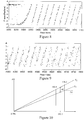
- This figure shows the phase difference of the Rayleigh scatter signal between a reference scan and a measurement scan at the beginning of a section of fiber that enters a region that is under tension.
- the data is plotted as a function of fiber index, which represents distance along the fiber.
- the phase difference begins to accumulate. Since ⁇ and - ⁇ have the same value on the unit circle, the signal experiences "wrapping" every multiple of 2 ⁇ as the phase difference grows along the length of the fiber. This can be seen around index 3350 where the values to the left of this are approaching ⁇ , and then suddenly the values are at - ⁇ .
- each wrap represents about 500 nm of length change in the fiber. Since an index represents about 50 microns of length, it takes about one hundred wraps of the phase to accumulate a full index of delay change between measurement and reference.
- the data in figure 9 is from the same data set as that for figure 8 , but from an area further down the fiber after about 35 wraps of the phase, or, roughly one third of an index.
- the noise on the phase difference data has increased and is caused by the increasing shift between the reference and measurement scatter patterns. This decreases the coherence between the reference and measurement data used to determine the phase difference. If the apparent location of an individual scattering fiber segment shifts by more than an index, then the coherence between the reference and the measurement is lost, and no strain measurement can be obtained from the comparison of scatter signals.
- the reference data should be matched to the measurement data by accounting for the shifting due to strain along the fiber.
- one index being about 50 microns, over a one meter segment, this amounts to only 50 parts per million, which is not a large strain.
- the weight of the fiber itself can induce strains on this order.
- a change in temperature of only a few degrees Celsius can induce a similar shift. Therefore, this shift in index should be accounted for in the calculation of the distortion of the core.
- a shift as a result of tension is a physical expansion of the individual segments which results in an increased time of flight of the scattered light.
- the shift between reference and measurement is referred to as delay.
- the phase for a given delay sweeps over a range of ⁇ ⁇ .
- the difference in this sweep range, ⁇ ⁇ 2 - ⁇ ⁇ 1 is less than the change in phase at the center frequency, (193.5 THz), labeled d ⁇ .
- the factor between the change in phase at the center frequency and the change in phase sweep range will be the ratio of the center frequency to the frequency sweep range. In this example case, the ratio is 96.7.
- the sweep range, ⁇ v determines the spatial resolution, ⁇ , of the measurement. In other words, it determines the length of an index in the time domain.
- the length of an index is 0.5 ps, or 50 microns in glass.
- a phase shift of 2 ⁇ is induced by a change in delay of only 0.00516 ps, or 516 nm in glass.
- a phase shift of 2 ⁇ represents only a fractional index shift in the time domain data.
- the delay In order to shift the delay by one index in the time domain, the delay must change enough to induce a phase change at the center frequency of 96.7 x 2 ⁇ .
- a linear phase change represents a shift in the location of events in the time, or delay, domain.
- a shift of one index will completely distort the measurements of phase change along the length of the fiber.
- these shifts should be accounted for as they happen, and the reference data should be aligned with the measurement data down the entire length of the core.
- a temporal shift of the reference data is required. This may be accomplished by multiplying the reference data for a given segment, r n , by a linear phase.
- n represents the index in the time domain, or increasing distance along the fiber.
- the slope of this phase correction, ⁇ is found by performing a linear fit on the previous delay values.
- the phase offset in this correction term, ⁇ is selected such that the average value of this phase is zero.
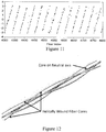
- Figure 11 shows the corrected phase difference over a section of fiber where a third of an index shift has occurred.
- the phase difference at this location maintains the same signal-to-noise ratio as the closer part of the fiber.
- Tracking distortions in the Rayleigh scatter of optical fiber provides high resolution, continuous measurements of strain.
- the geometry of the multi-core shape sensing fiber is used to explain how this multi-core structure enables measurements of both bend and bend direction along the length of the fiber.
- the optical fiber contains multiple cores in a configuration that allows the sensing of both an external twist and strain regardless of bend direction.
- One non-limiting, example embodiment of such a fiber is shown in Figure 1 and described below.
- the fiber contains four cores. One core is positioned along the center axis of the fiber.
- the three outer cores are placed concentric to this core at 120 degree intervals at a separation of 70um.
- the outer cores are rotated with respect to the center core creating a helix with a period of 66 turns per meter.
- An illustration of this helically-wrapped multi-core shape sensing fiber is depicted in figure 12 .
- a layout of a non-limiting test multi-core optical fiber used in this discussion is pictured in figure 13 .
- shape sensing fiber contains more than three outer cores to facilitate manufacture of the fiber or to acquire additional data to improve system performance.
- each outer core appears to rotate around the center core progressing down the length of the fiber as illustrated in figure 14 .
- the rotational position of an outer core must be determined with a high degree of accuracy. Assuming a constant spin rate of the helix (see figure 12 ), the position of the outer cores may be determined based on the distance along the fiber. In practice, the manufacture of helixed fiber introduces some variation in the intended spin rate. The variation in spin rate along the length of the fiber causes an angular departure from the linear variation expected from the nominal spin rate, and this angular departure is referred to as a "wobble" and symbolized as a wobble signal W ( z ).
- One example test fiber manufactured with a helical multi-core geometry has a very high degree of accuracy in terms of the average spin rate, 66 turns per meter.
- the spin rate varies significantly, and can cause the angular position to vary as much as 12 degrees from a purely linear phase change with distance.
- This error in the spin rate is measured by placing the fiber in a configuration that will cause a continuous bend in a single plane, as is the case for a coiled fiber on a flat surface.
- a helical core will alternate between tension and compression as it travels through the outside portion of a bend and the inside portion of a bend. If phase distortion is plotted versus distance, a sinusoidal signal is formed with a period that matches the spin rate of the fiber. Variations in the manufacture of the multi-core fiber can be detected as small shifts in the phase from the expected constant spin rate of the fiber.
- Figure 16 shows an example Wobble signal, W(z), with a periodic variation from a manufactured spin rate along the length of a shape sensing fiber.
- the phase variation is shown as a function of length in fiber index.
- the example data set represents about three meters of fiber.
- a periodicity in the nature of the spin rate of the fiber is detected.
- Over the length of the fiber a consistent average spin rate of the fiber is produced, but these small fluctuations should be calibrated in order to correctly interpret the phase data produced by the multi-core twisted fiber. This measurement in the change in spin rate or "wobble" is reproducible and is important to the calculation of shape given practical manufacture of fiber.
- Torsion forces applied to the fiber also have the potential to induce a rotational shift of the outer cores.
- both wobble and applied twist must be measured along the entire length of the shape sensing fiber.
- the geometry of the helixed multi-core fiber enables direct measurement of twist along the length of the fiber in addition to bend-induced strain as will be described below.
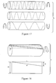
- a multi-core fiber is rotated as it is drawn, the central core is essentially unperturbed, while the outer cores follow a helical path down the fiber as shown in the center of figure 17 . If such a structure is then subjected to torsional stress, the length of the central core remains constant. However, if the direction of the torsional stress matches the draw of the helix, the period of the helix increases and the outer cores will be uniformly elongated as shown at the top of figure 17 . Conversely, if the torsional direction is counter to the draw of the helix, the outer cores are "unwound" and experience a compression along their length as shown at the bottom of figure 17 .
- a segment of fiber is modeled as a cylinder.
- the length L of the cylinder corresponds to the segment size, while the distance from the center core to an outer core represents the radius r of the cylinder.
- the surface of a cylinder can be represented as a rectangle if one slices the cylinder longitudinally and then flattens the surface.
- the length of the surface equals the segment length L while the width of the surface corresponds to the circumference of the cylinder 2 ⁇ r .
- the end point of fiber moves around the cylinder, while the beginning point remains fixed. Projected on the flattened surface, the twisted core forms a diagonal line that is longer than the length L of the rectangle. This change in length of the outer core is related to the twist in the fiber.
- Figure 18 shows an outer core that experiences twist can be modeled as a flattened cylinder as it translates along the surface. From the above flattened surface, the following can be shown: ⁇ d ⁇ 2 ⁇ r 2 L ⁇ ⁇
- ⁇ d is the change in length of the outer core due to the change in rotation, ⁇ ⁇ , of the fiber from its original helixed state.
- the radial distance between a center core and an outer core is represented by r
- 2 ⁇ ⁇ L is the spin rate of the helical fiber in rotation per unit length.
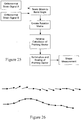
- the external twist along the fiber may be calculated using non-limiting, example procedures outlined in the flow chart shown in figure 19 .
- the phase signals for all four cores A-D are determined, and the signals for outer cores B-D are averaged.
- the calculation of extrinsic twist is performed by comparing the average of the outer core phase signals to that of the center core. If the fiber experiences a torsional force, all outer cores experience a similar elongation or compression determined by the orientation of the force to the spin direction of the helix.
- the center core does not experience a change in length as a result of an applied torsional force. However, the center core is susceptible to tension and temperature changes and serves as a way of directly measuring common strain modes.
- phase change as a result of torsion is obtained.
- This phase change can be scaled to a measure of extrinsic twist, or in other words, fiber rotation. Within the region of an applied twist over the length of the fiber less than a full rotation, this scale factor can be approximated as linear. In the presence of high torsional forces, a second order term should preferably be considered. Further, twist distributes linearly between bonding points such that various regions of twist can be observed along the length of the fiber..
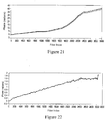
- Figure 20 shows an example data set for a generic shape that illustrates the figure 19 algorithm in more detail.
- the graph shows phase distortion as a result of local change in length of the center core (black) and an outer core (gray) of a shape sensing fiber for a general bend.
- the two phase curves shown in Figure 20 represent the local changes in length experience by two of the cores in the multi-core shape sensing fiber.
- the curves for two of the outer cores are not shown in an effort to keep the graphs clear, but the values from these other two cores are used in determining the final shape of the fiber.
- the three, corrected, outer core phase signals are used to extract a measure of bend along the shape sensing fiber. Due to symmetry, two of the outer cores can be used to reconstruct the strain signals along the length of the fiber.
- the derivative of the phase signal for two of the outer cores is taken. This derivative is preferably calculated so that the error on the integral of the derivative is not allowed to grow, which translates to a loss in accuracy of the system. For double-precision operations, this is not a concern. But if the operations are done with a limited numeric precision, then rounding must be applied such that the value of the integral does not accumulate error (convergent rounding).
- b y z 1 sin ⁇ 1 ⁇ ⁇ 2 d ⁇ 1 dz cos kz + ⁇ 2 + d ⁇ 2 dz cos kz + A 1
- b x z 1 sin ⁇ 2 ⁇ ⁇ 1 d ⁇ 1 dz sin kz + ⁇ 2 + d ⁇ 2 dz sin kz + ⁇ 1
- Equations (14) and (15) produce two differential, orthogonal strain signals.
- Figure 24 depicts the orthogonal strain curves for a fiber placed in several bends that all occur in the same plane.
- These two differential, orthogonal strain signals are processed to perform the final integration along the length of the shape sensing fiber to produce three Cartesian signals representing the position and/or shape of the fiber.
- Figure 25 shows a flowchart diagram describing non-limiting, example steps for calculating shape from strain.
- Orthonormal strain signals A and B are determined according to the equations 14 and 15.
- the acquired data at the data acquisition network is preferably stored in discrete arrays in computer memory. To do this, a change in representation from the continuous representation in equation 15 to a discrete representation based on index is needed at this point. Further, the bend at each point in the array can be converted to an angular rotation since the length of the segment ( ⁇ z ) is fixed and finite using equation (1).
- the parameter, a is determined by the distance of the cores from the center of the fiber and the strain-optic coefficient which is a proportionality constant relating strain to change in optical path length.
- the above rotation matrix is valid if ⁇ x ⁇ 1 and ⁇ y ⁇ 1 . If the resolution of the system is on the order of micrometers, this is a condition that is not difficult to maintain. After rotation, the fiber segment will have a new end point and a new direction. All further bends are measured from this new pointing direction. Therefore, the pointing direction (or vector) at any position on the fiber depends upon all of the pointing directions between that location in the fiber and the starting location.
- each segment along the fiber introduces a small rotation proportional to the size and direction of the bend along that segment.
- the angles are effectively summed, and by maintaining an accurate measure of the integral of the strain (the length change) throughout the length of the shape sensing fiber, better accuracy is achieved than is possible using the strain alone.
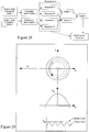
- the System Controller and data processor ( A ) initiates two consecutive sweeps of a tunable laser ( B ) over a defined wavelength range and tuning rate.
- Light emitted from the tunable laser is routed to two optical networks via an optical coupler ( C ).
- the first of these two optical networks is a Laser Monitor Network ( E ) while the second is designated as an Interrogator Network ( D ).
- an optical coupler ( F ) Within the Laser Monitor Network ( E ), light is split via an optical coupler ( F ) and sent to a gas (e.g., Hydrogen Cyanide) cell reference ( G ) used for C-Band wavelength calibration.
- the gas cell spectrum is acquired by a photodiode detector ( L ) linked to a Data Acquisition Network ( U ).
- the remaining portion of light split at optical coupler ( F ) is routed to an interferometer constructed from an optical coupler ( H ) attached to two Faraday Rotator Mirrors ( I,J ).
- the first Faraday Rotator Mirror (FRMs) ( I ) serves as the reference arm of the interferometer while the second Faraday Rotator Mirror ( J ) is distanced by a delay spool ( K ) of optical fiber.
- This interferometer produces a monitor signal that is used to correct for laser tuning nonlinearity and is acquired by the Data Acquisition Network ( U ) via a photodiode detector ( M ).
- optical coupler ( C ) Light routed to the Interrogator Network ( D ) by optical coupler ( C ) enters a polarization controller ( N ) that rotates the laser light to an orthogonal state between the two successive laser scans. This light is then split via a series of optical couplers ( O ) evenly between four acquisition interferometers ( P, Q, R, S ). Within the acquisition interferometer for the central core, light is split between a reference path and a measurement path by an optical coupler ( AA ). The "probe" laser light from coupler AA passes through an optical circulator ( T ) and enters a central core of a shape sensing fiber ( W ) through a central core lead of a multi-core fanout ( V ) for the shape sensing fiber ( W ).
- the shape sensing fiber ( W ) contains a central optical core concentric to three helically wound outer optical cores.
- the cross section of the fiber ( X ) depicts that the outer cores ( Z ) are evenly spaced, concentric, and separated by a given radial distance from the central core ( Y ).
- the resulting Rayleigh backscatter of the central optical core ( Y ) as a consequence of a laser scan passes through the optical circulator ( T ) and interferes with the reference path light of the acquisition interferometer when recombined at optical coupler ( BB ).
- the interference pattern passes through an optical polarization beam splitter ( DD ) separating the interference signal into the two principle polarization states (S 1 , P 1 ).
- Each of the two polarization states is acquired by the Data Acquisition Network ( U ) using two photodiode detectors ( EE, FF ).
- a polarization rotator ( CC ) can be adjusted to balance the signals at the photodiode detectors.
- the outer optical cores of the shape sensing fiber are measured in a similar manner using corresponding acquisition interferometers (Q, R, S).
- the System Controller and Data Processor ( A ) interprets the signals of the four individual optical cores and produces a measurement of both position and orientation along the length of the shape sensing fiber ( W ). Data is then exported from the System Controller ( A ) for display and/or use ( GG ).
- the flowchart diagram in figure 28 outlines a non-limiting, example process for correcting for birefringence such as intrinsic birefringence, bend-induced birefringence, etc. both in measured and in reference values.
- the non-limiting example below relates to bend-induced birefringence but is more generally applicable to any birefringence.
- the first step in the process is to measure the response of the core at two orthogonal polarization states called "s" and "p".
- An s response and a p response are measured at each polarization state resulting in four arrays.
- the responses to the first polarization state are called a and b
- the responses to the second polarization state are called c and d, where a and c are the responses at the s detector and b and d are the responses at the p detector.
- ⁇ ⁇ ⁇ ⁇ ae i ⁇ u * ⁇ , ⁇ be i ⁇ u * ⁇ , ⁇ ce i ⁇ u * ⁇ , ⁇ de i ⁇ u * ⁇ ⁇
- ⁇ n ⁇ ⁇ ⁇ n ⁇ ⁇ ⁇ 0 *
- ⁇ n the correction due to birefringence effects
- n the index into the array.
- the vector is shown compared to the first element (index 0) in the array, but it can just as easily be compared with any arbitrarily selected element in the vector array.
- the birefringence correction compensates for birefringence as result of core asymmetry during manufacture and for bend radii in excess of 100mm. As the shape sensing fiber is placed into tight bends with radii less than 100mm, a second order birefringence effect becomes significant.
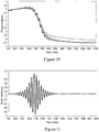
- Figure 30 shows two phase plots produced from a 40mm diameter fiber loop. Oscillations in these signals are a result of the multi-core assembly being off center of the fiber. In tighter bends, strain signals are high enough to elicit a response from this subtle deviation from concentricity.
- the plot shows that the average of the helical outer cores accumulates significantly less phase in the region of the bend when compared to the center core. This phase deficiency serves as evidence for bend induced birefringence.
- the extrinsic twist calculation is performed by finding the absolute phase difference between the center core and the average of the three outer cores. The graph in figure 30 shows that a false twist signal will be measured in the region of the bend.
- a loop polarization controller is added between the shape sensing fiber and the shape sensing system as illustrated in figure 34 .
Claims (15)
- Procédé de mesure de position et/ou de forme d'une fibre multicoeur comprenant le fait :pour chaque coeur d'au moins deux coeurs dans la fibre multicoeur, de déterminer un changement total de la longueur optique jusqu'à un point sur la fibre multicoeur, le changement total des longueurs optiques comportant une accumulation de tous les changements de la longueur optique dans ce coeur pour plusieurs longueurs de segments jusqu'au point sur la fibre multicoeur, etde déterminer l'emplacement ou la direction de pointage au niveau du point sur la fibre multicoeur sur la base des changements totaux de la longueur optique.
- Procédé de la revendication 1, dans lequel, pour chaque coeur des au moins deux coeurs, la détermination du changement total de la longueur optique comporte le fait de détecter un changement progressif de la longueur optique dans ce coeur pour chaque segment des plusieurs longueurs de segments jusqu'au point sur la fibre multicoeur, et où les changements totaux de la longueur optique pour ce coeur sont basés sur une combinaison des changements progressifs.
- Procédé de la revendication 2, dans lequel, pour chaque coeur des aux moins deux coeurs, la détection du changement progressif de la longueur optique dans ce coeur pour chaque segment des plusieurs longueurs de segments comporte le fait de détecter une réponse en phase d'un signal lumineux réfléchi dans ce coeur à partir des plusieurs longueurs de segments, et où une contrainte sur la fibre multicoeur au niveau des plusieurs longueurs de segments provoque un décalage de la réponse en phase du signal lumineux réfléchi par rapport aux plusieurs longueurs de segments.
- Procédé de la revendication 3, comprenant en outre la surveillance de la réponse en phase de manière continue le long d'une longueur optique de la fibre multicoeur.
- Procédé de la revendication 2, comprenant en outre le fait :
de déterminer un paramètre de torsion associé à la fibre multicoeur au niveau du point sur la fibre multicoeur sur la base des changements totaux de la longueur optique de la fibre multicoeur. - Procédé de la revendication 5, dans lequel la détermination de l'emplacement ou de la direction de pointage au niveau du point sur la fibre multicoeur est basée sur le paramètre de torsion déterminé.
- Procédé de la revendication 1, dans lequel la fibre multicoeur est enroulée de manière hélicoïdale et est caractérisée par une vitesse de rotation nominale, le procédé comprenant en outre le fait :de déterminer une variation de la vitesse de rotation nominale au niveau du point le long de la fibre multicoeur, etde corriger la variation.
- Procédé de la revendication 1, comprenant en outre le fait :de transmettre de la lumière avec au moins deux états de polarisation le long de la fibre multicoeur, les au moins deux états de polarisation étant nominalement orthogonaux, etdans lequel la détermination de l'emplacement ou de la direction de pointage au niveau du point sur la fibre multicoeur comprend le fait :
de calculer les changements indépendant de la polarisation de la longueur optique dans les au moins deux coeurs dans la fibre multicoeur jusqu'au point sur la fibre multicoeur en utilisant les réflexions de la lumière. - Procédé de la revendication 5, comprenant en outre le fait :de déterminer les changements induits par pliage de la longueur optique le long de la fibre multicoeur, etde prendre en considération des changements induits par pliage de la longueur optique lors de la détermination du paramètre de torsion.
- Appareil permettant d'effectuer des mesures de position et/ou de forme d'une fibre multicoeur, comprenant :des circuits de détection configurés pour détecter, pour chaque coeur des au moins deux coeurs dans la fibre multicoeur, un changement total de la longueur optique jusqu'à un point sur la fibre multicoeur, le changement total de la longueur optique comportant une accumulation de tous les changements de la longueur optique pour plusieurs longueurs de segments jusqu'au point sur la fibre multicoeur, etdes circuits de calcul configurés pour déterminer l'emplacement ou la direction de pointage au niveau du point sur la fibre multicoeur sur la base des changements totaux de la longueur optique.
- Appareil de la revendication 10, dans lequel, pour chaque coeur des au moins deux coeurs, les circuits de détection sont configurés pour détecter un changement progressif de la longueur optique dans ce coeur des coeurs pour chaque longueur de segment des plusieurs longueurs de segments jusqu'au point sur la fibre multicoeur, et dans lequel les changements totaux de la longueur optique pour ce coeur sont basés sur une combinaison des changements progressifs, et
dans lequel, pour chaque coeur des au moins deux coeurs, les circuits de détection sont configurés pour détecter une réponse en phase d'un signal lumineux réfléchi dans ce coeur à partir des plusieurs longueurs de segments, et où une contrainte sur la fibre au niveau des plusieurs longueurs de segments entraîne un décalage de la réponse en phase du signal lumineux réfléchi à partir des plusieurs longueurs de segments. - Appareil de la revendication 11, dans lequel les circuits de détection sont configurés pour surveiller la réponse en phase de manière continue le long d'une longueur optique de la fibre multicoeur.
- Appareil de la revendication 10, comprenant en outre :un laser configuré pour transmettre de la lumière avec au moins deux états de polarisation le long de la fibre multicoeur,dans lequel les circuits de calcul sont configurés pour combiner les réflexions de la lumière avec les au moins deux états de polarisation dans la détermination de l'emplacement ou de la direction de pointage au niveau du point sur la fibre multicoeur sur la base des changements totaux de la longueur optique.
- Appareil de la revendication 13, dans lequel les deux états de polarisation comportent un premier état de polarisation et un deuxième état de polarisation, le deuxième état de polarisation étant nominalement orthogonal au premier état de polarisation, l'appareil comprenant en outre un dispositif de commande de polarisation configuré pour transmettre un premier signal lumineux au premier état de polarisation le long de la fibre multicoeur et transmettre un deuxième signal lumineux au deuxième état de polarisation le long de la fibre multicoeur, et dans lequel les circuits de calcul sont configurés pour calculer un changement indépendant de la polarisation de la longueur optique dans les au moins deux coeurs dans la fibre multicoeur jusqu'au point sur la fibre multicoeur en utilisant des réflexions des premier et deuxième signaux lumineux.
- Support de stockage non transitoire stockant des instructions de programme qui, lorsqu'elles sont exécutées sur un dispositif de mesure informatisé, amènent le dispositif de mesure informatisé à effectuer des mesures d'une fibre multicoeur en réalisant le procédé de l'une des revendications 1 à 9.
Priority Applications (2)
| Application Number | Priority Date | Filing Date | Title |
|---|---|---|---|
| EP23192524.9A EP4279896A3 (fr) | 2009-09-18 | 2010-09-16 | Détection de position et/ou de forme optique |
| EP19162603.5A EP3521752B1 (fr) | 2009-09-18 | 2010-09-16 | Détection de position et/ou de forme optique |
Applications Claiming Priority (5)
| Application Number | Priority Date | Filing Date | Title |
|---|---|---|---|
| US24374609P | 2009-09-18 | 2009-09-18 | |
| US25557509P | 2009-10-28 | 2009-10-28 | |
| US35034310P | 2010-06-01 | 2010-06-01 | |
| US12/874,901 US8773650B2 (en) | 2009-09-18 | 2010-09-02 | Optical position and/or shape sensing |
| PCT/US2010/002517 WO2011034584A2 (fr) | 2009-09-18 | 2010-09-16 | Détection de position et/ou de forme optique |
Related Child Applications (3)
| Application Number | Title | Priority Date | Filing Date |
|---|---|---|---|
| EP23192524.9A Division EP4279896A3 (fr) | 2009-09-18 | 2010-09-16 | Détection de position et/ou de forme optique |
| EP19162603.5A Division EP3521752B1 (fr) | 2009-09-18 | 2010-09-16 | Détection de position et/ou de forme optique |
| EP19162603.5A Division-Into EP3521752B1 (fr) | 2009-09-18 | 2010-09-16 | Détection de position et/ou de forme optique |
Publications (3)
| Publication Number | Publication Date |
|---|---|
| EP2478331A2 EP2478331A2 (fr) | 2012-07-25 |
| EP2478331A4 EP2478331A4 (fr) | 2017-06-28 |
| EP2478331B1 true EP2478331B1 (fr) | 2019-04-24 |
Family
ID=43759221
Family Applications (3)
| Application Number | Title | Priority Date | Filing Date |
|---|---|---|---|
| EP19162603.5A Active EP3521752B1 (fr) | 2009-09-18 | 2010-09-16 | Détection de position et/ou de forme optique |
| EP10817557.1A Active EP2478331B1 (fr) | 2009-09-18 | 2010-09-16 | Détection de position et/ou de forme optique |
| EP23192524.9A Pending EP4279896A3 (fr) | 2009-09-18 | 2010-09-16 | Détection de position et/ou de forme optique |
Family Applications Before (1)
| Application Number | Title | Priority Date | Filing Date |
|---|---|---|---|
| EP19162603.5A Active EP3521752B1 (fr) | 2009-09-18 | 2010-09-16 | Détection de position et/ou de forme optique |
Family Applications After (1)
| Application Number | Title | Priority Date | Filing Date |
|---|---|---|---|
| EP23192524.9A Pending EP4279896A3 (fr) | 2009-09-18 | 2010-09-16 | Détection de position et/ou de forme optique |
Country Status (8)
| Country | Link |
|---|---|
| US (9) | US8773650B2 (fr) |
| EP (3) | EP3521752B1 (fr) |
| JP (1) | JP5506935B2 (fr) |
| CN (3) | CN102695938B (fr) |
| BR (1) | BR112012008347B1 (fr) |
| IN (1) | IN2012DN02224A (fr) |
| RU (1) | RU2541139C2 (fr) |
| WO (1) | WO2011034584A2 (fr) |
Families Citing this family (111)
| Publication number | Priority date | Publication date | Assignee | Title |
|---|---|---|---|---|
| US8773650B2 (en) | 2009-09-18 | 2014-07-08 | Intuitive Surgical Operations, Inc. | Optical position and/or shape sensing |
| US8265431B2 (en) * | 2009-11-06 | 2012-09-11 | Baker Hughes Incorporated | Rotated single or multicore optical fiber |
| JP2011237782A (ja) * | 2010-04-13 | 2011-11-24 | Sumitomo Electric Ind Ltd | 光分岐素子及びそれを含む光通信システム |
| EP2577221B1 (fr) | 2010-06-01 | 2019-04-24 | Intuitive Surgical Operations Inc. | Mesure interférométrique avec suppression de la diaphonie |
| WO2012101562A1 (fr) * | 2011-01-28 | 2012-08-02 | Koninklijke Philips Electronics N.V. | Capteur optique de fibre pour déterminer une forme tridimensionnelle |
| JP6188685B2 (ja) | 2011-06-10 | 2017-08-30 | コーニンクレッカ フィリップス エヌ ヴェKoninklijke Philips N.V. | 介入治療に対するアプリケータ配置のリアルタイム変化を決定する光ファイバ感知 |
| EP2721434B1 (fr) * | 2011-06-14 | 2021-05-05 | Intuitive Surgical Operations, Inc. | Mise en coïncidence d'âmes dans des systèmes de détection de fibres optiques multi-âmes |
| JP5741313B2 (ja) * | 2011-08-12 | 2015-07-01 | 株式会社大林組 | モード解析方法、モード解析システム、変位計測方法、および変位計測システム |
| MX342395B (es) | 2011-09-02 | 2016-09-28 | Koninklijke Philips Nv | Informacion de insercion y egreso de dispositivo medico utilizando deteccion distribuida de temperatura con fibra optica. |
| JP2013080126A (ja) * | 2011-10-04 | 2013-05-02 | Sumitomo Electric Ind Ltd | 偏波保持マルチコア光ファイバ |
| US20130094798A1 (en) * | 2011-10-12 | 2013-04-18 | Baker Hughes Incorporated | Monitoring Structural Shape or Deformations with Helical-Core Optical Fiber |
| JP6214550B2 (ja) | 2011-12-05 | 2017-10-18 | インテュイティブ サージカル オペレーションズ, インコーポレイテッド | 干渉検知システムの動き補償のための方法及び装置 |
| WO2013136247A1 (fr) | 2012-03-16 | 2013-09-19 | Koninklijke Philips N.V. | Système de détection optique pour déterminer la position et/ou la forme d'un objet associé |
| US10267709B2 (en) * | 2012-05-07 | 2019-04-23 | Nederlandse Organisatie Voor Toegepast-Natuurwetenschappelijk Onderzoek Tno | Optical sensor interrogation system a method of manufacturing the optical sensor interrogation system |
| US9429696B2 (en) | 2012-06-25 | 2016-08-30 | Intuitive Surgical Operations, Inc. | Systems and methods for reducing measurement error in optical fiber shape sensors |
| DE102012106806B4 (de) * | 2012-07-26 | 2022-07-28 | J-Fiber Gmbh | Sensorfaser zur Temperatur-, Dehnungs- und/oder Torsionsdetektion in Form eines Mehrkern-Lichtwellenleiters mit einer Fiber-Bragg-Gitterstruktur |
| US8746076B2 (en) | 2012-08-22 | 2014-06-10 | The United States Of America As Represented By The Administrator Of The National Aeronautics And Space Administration | Shape sensing using a multi-core optical fiber having an arbitrary initial shape in the presence of extrinsic forces |
| WO2014053934A1 (fr) * | 2012-10-01 | 2014-04-10 | Koninklijke Philips N.V. | Système et procédé permettant d'enregistrer une détection de forme avec une imagerie à l'aide d'un plan optimal |
| EP2720388A1 (fr) | 2012-10-15 | 2014-04-16 | Koninklijke Philips N.V. | Système de réflectométrie de domaine de fréquence optique (OFDR) |
| WO2014060889A1 (fr) | 2012-10-16 | 2014-04-24 | Koninklijke Philips N.V. | Pléthysmographie pulmonaire basée sur une détection de forme optique |
| WO2014072845A1 (fr) | 2012-11-09 | 2014-05-15 | Koninklijke Philips N.V. | Système de réflectométrie en domaine de fréquences optiques (ofdr) ayant de multiples fibres par chaîne de détection |
| RU2551802C2 (ru) * | 2012-12-18 | 2015-05-27 | Владимир Васильевич Гришачев | Устройство защиты оптической сети от несанкционированного зондирования методами оптической рефлектометрии |
| WO2014105911A1 (fr) * | 2012-12-24 | 2014-07-03 | Luna Innovations Incorporated | Correction de dispersion dans une réflectométrie de domaine de fréquence optique (ofdr) |
| CN103901532A (zh) * | 2012-12-26 | 2014-07-02 | 西安金和光学科技有限公司 | 多芯光纤、采用该多芯光纤的传感装置及其运行方法 |
| WO2014117780A1 (fr) | 2013-02-01 | 2014-08-07 | National Oilwell Varco Denmark I/S | Conduite montante armée flexible non liée |
| WO2014125388A1 (fr) | 2013-02-14 | 2014-08-21 | Koninklijke Philips N.V. | Système interventionnel |
| WO2014136020A2 (fr) * | 2013-03-07 | 2014-09-12 | Koninklijke Philips N.V. | Suréchantillonage adaptatif pour interpolations en temps réel précises |
| EP3008425B1 (fr) | 2013-06-13 | 2018-08-08 | Intuitive Surgical Operations, Inc. | Fibre de détection à réseau de bragg sur fibre à pas variable et à chevauchement, et procédés et appareil pour une mesure de paramètre à l'aide cette dernière |
| EP3011490B1 (fr) * | 2013-06-18 | 2018-09-26 | Intuitive Surgical Operations, Inc. | Procédés et appareil pour l'étalonnage segmenté d'une fibre optique de détection |
| US9464883B2 (en) | 2013-06-23 | 2016-10-11 | Eric Swanson | Integrated optical coherence tomography systems and methods |
| US9683928B2 (en) * | 2013-06-23 | 2017-06-20 | Eric Swanson | Integrated optical system and components utilizing tunable optical sources and coherent detection and phased array for imaging, ranging, sensing, communications and other applications |
| WO2015017270A1 (fr) * | 2013-07-29 | 2015-02-05 | Intuitive Surgical Operations, Inc. | Systèmes de capteur de forme avec détection redondante |
| JP6480938B2 (ja) | 2013-09-06 | 2019-03-13 | コーニンクレッカ フィリップス エヌ ヴェKoninklijke Philips N.V. | ナビゲーションシステム |
| US9216004B2 (en) | 2013-09-12 | 2015-12-22 | Jesse Talant | Adam and ease mammography device |
| WO2015044930A1 (fr) * | 2013-09-30 | 2015-04-02 | Koninklijke Philips N.V. | Rejet d'un profil spécifique à un dispositif pour une détection de forme optique stable |
| CN103604382A (zh) * | 2013-11-01 | 2014-02-26 | 河海大学 | 一种波纹管分布式光纤测量传感器 |
| US9304018B2 (en) * | 2013-11-05 | 2016-04-05 | Intuitive Surgical Operations, Inc. | Body shape, position, and posture recognition suit with multi-core optical shape sensing fiber |
| US10060723B2 (en) * | 2014-01-17 | 2018-08-28 | Harbin Institute Of Technology | Method and equipment based on multi-core fiber Bragg grating probe for measuring structures of a micro part |
| US9494416B2 (en) * | 2014-02-06 | 2016-11-15 | Baker Hughes Incorporated | Fiber optic shape sensing system using anchoring points |
| US11067387B2 (en) * | 2014-02-28 | 2021-07-20 | Koninklijke Philips N.V. | Adaptive instrument kinematic model optimization for optical shape sensed instruments |
| JP2015181643A (ja) * | 2014-03-24 | 2015-10-22 | オリンパス株式会社 | 湾曲形状推定システム、管状挿入システム、及び、湾曲部材の湾曲形状推定方法 |
| US9681107B2 (en) | 2014-05-22 | 2017-06-13 | Siemens Energy, Inc. | Flexible tether position tracking camera inspection system for visual inspection of off line industrial gas turbines and other power generation machinery |
| US9359910B2 (en) | 2014-05-29 | 2016-06-07 | Siemens Energy, Inc. | Method and apparatus for measuring operational gas turbine engine housing displacement and temperature by a distributed fiber optic sensing system utilizing optical frequency domain reflectometry |
| US20160018245A1 (en) * | 2014-07-17 | 2016-01-21 | Schlumberger Technology Corporation | Measurement Using A Multi-Core Optical Fiber |
| US10295380B2 (en) | 2014-08-22 | 2019-05-21 | Luna Innovations Incorporated | Method and apparatus for multiple localized interferometric measurements |
| US10422631B2 (en) | 2014-11-11 | 2019-09-24 | Luna Innovations Incorporated | Optical fiber and method and apparatus for accurate fiber optic sensing under multiple stimuli |
| US10132995B2 (en) * | 2014-12-09 | 2018-11-20 | General Electric Company | Structures monitoring system and method |
| JP6820848B2 (ja) * | 2014-12-11 | 2021-01-27 | コーニンクレッカ フィリップス エヌ ヴェKoninklijke Philips N.V. | 改善されたmri安全性のためのケーブルループ検知機構 |
| WO2016099976A1 (fr) * | 2014-12-15 | 2016-06-23 | Intuitive Surgical Operations, Inc. | Cœurs dissemblables dans une fibre optique à cœurs multiples pour séparation de la contrainte et de la température |
| US10405908B2 (en) | 2014-12-18 | 2019-09-10 | Warsaw Orthopedic, Inc. | Apparatus and method for forming support device for effecting orthopedic stabilization |
| WO2016110467A1 (fr) * | 2015-01-08 | 2016-07-14 | Koninklijke Philips N.V. | Système de détection de forme optique, appareil médical et procédé de détection de forme optique |
| US10416391B2 (en) | 2015-03-27 | 2019-09-17 | Intuitive Surgical Operations, Inc. | Interferometric alignment of optical multicore fibers to be connected |
| EP3278079B1 (fr) | 2015-04-02 | 2020-06-03 | Intuitive Surgical Operations, Inc. | Enregistrement de données mesurées d'interférométrie par fibre optique avec des données de référence d'interférométrie par fibre optique |
| WO2016178279A1 (fr) * | 2015-05-01 | 2016-11-10 | オリンパス株式会社 | Appareil de déduction d'informations de flexion, système d'endoscope équipé de l'appareil de déduction d'informations de flexion, procédé de déduction d'informations de flexion, et programme de déduction d'informations de flexion |
| US10378883B2 (en) | 2015-05-15 | 2019-08-13 | Intuitive Surgical Operations, Inc. | Force sensing in a distal region of an instrument including single-core or multi-core optical fiber |
| JP2018527041A (ja) * | 2015-06-15 | 2018-09-20 | コーニンクレッカ フィリップス エヌ ヴェKoninklijke Philips N.V. | 後方散乱反射光測定を用いて医療デバイスの位置及び/又は形状を感知するための光学的形状感知システム並びに方法 |
| US10551168B2 (en) | 2015-06-16 | 2020-02-04 | Karlsruher Institut Fur Technologie | Deformation device, including an optical waveguide and method for measuring deformation of a tubular structure at multiple measuring points |
| PL235392B1 (pl) | 2015-06-24 | 2020-07-13 | Bednarski Lukasz | Sposób ciągłego pomiaru profilu przemieszczeń obiektów budowlanych oraz czujnik do realizacji tego sposobu |
| US10390884B2 (en) | 2015-06-30 | 2019-08-27 | DePuy Synthes Products, Inc. | Methods and templates for shaping patient-specific anatomical-fixation implants |
| CN107920716B (zh) * | 2015-07-10 | 2020-11-03 | 奥林巴斯株式会社 | 形状检测插入装置 |
| US9726573B2 (en) * | 2015-08-19 | 2017-08-08 | Anritsu Corporation | Optical frequency domain reflectometry, optical frequency domain reflectometer, and device for measuring position or shape using the same |
| US10302463B2 (en) * | 2015-11-19 | 2019-05-28 | Corning Incorporated | Distributed fiber sensors and systems employing multicore optical fibers |
| CN108351295B (zh) * | 2015-12-14 | 2021-06-29 | 直观外科手术操作公司 | 使用光纤形状感测生成解剖目标的三维数据的设备和方法 |
| US10690483B2 (en) | 2016-02-24 | 2020-06-23 | Koninklijke Philips N.V. | Methods and systems for correcting for nonlinear twist response in optical shape sensing with spun multicore fibers |
| EP3446161B1 (fr) | 2016-04-20 | 2021-09-01 | Koninklijke Philips N.V. | Procédés et systèmes permettant de connecter optiquement un capteur à fibre optique à une console de détection de forme optique |
| CN108603977B (zh) * | 2016-05-11 | 2020-08-07 | 直观外科手术操作公司 | 具有用于安全性的冗余纤芯的多纤芯光学纤维 |
| US10775157B2 (en) | 2016-06-09 | 2020-09-15 | Intuitive Surgical Operations, Inc. | Methods and apparatus for calibration for a fiber optic shape sensor |
| EP4137778A1 (fr) | 2016-06-29 | 2023-02-22 | Intuitive Surgical Operations, Inc. | Procédés et appareil pour la surveillance et l'optimisation d'un interrogateur ofdr |
| CN109313010B (zh) | 2016-07-08 | 2022-01-18 | 直观外科手术操作公司 | 用于安全的多芯纤维中冗余弯曲的计算 |
| US10145681B2 (en) | 2016-07-19 | 2018-12-04 | Corning Incorporated | Brillouin-based distributed bend fiber sensor and method for using same |
| WO2018063546A1 (fr) | 2016-09-27 | 2018-04-05 | Intuive Surgical Operations, Inc. | Ensembles micro-optiques et systèmes d'interrogation optique |
| EP3529579B1 (fr) | 2016-10-21 | 2021-08-25 | Intuitive Surgical Operations, Inc. | Détection de forme au moyen d'un capteur à fibres multicoeurs |
| EP3538947B1 (fr) | 2016-11-10 | 2021-12-01 | Intuitive Surgical Operations, Inc. | Système de mesure à fibre optique avec commande de polarisation à faible dispersion de mode de polarisation et procédé associé |
| EP3563119B1 (fr) | 2016-12-29 | 2021-10-20 | Intuitive Surgical Operations, Inc. | Procédés et appareil pour déterminer un ou plusieurs paramètres de forme à l'aide d'une fibre de détection ayant un coeur unique à multiples modes de propagation de lumière |
| JP6360929B1 (ja) | 2017-02-15 | 2018-07-18 | 株式会社フジクラ | 光ファイバセンサ |
| US10670389B2 (en) * | 2017-02-23 | 2020-06-02 | General Photonics Corporation | Sensitive optical fiber shape sensing based on shape-related optical polarization evolution |
| CN106949850B (zh) * | 2017-03-29 | 2019-05-24 | 哈尔滨工业大学 | 一种高灵敏度高精度的光纤形状传感测量方法及系统 |
| EP3449857A1 (fr) | 2017-08-29 | 2019-03-06 | Koninklijke Philips N.V. | Cathéter d'ablation, agencement de cathéter et système pour fournir un traitement ablatif |
| US10612911B1 (en) | 2017-09-07 | 2020-04-07 | United States Of America As Represented By The Administrator Of The National Aeronautics And Space Administration | Fiber optic system for monitoring displacement of a structure using quaternion kinematic shape sensing |
| JP6939360B2 (ja) | 2017-10-02 | 2021-09-22 | オムロン株式会社 | 共焦点計測装置 |
| US11761797B2 (en) | 2017-10-02 | 2023-09-19 | Intuitive Surgical Operations, Inc. | Optical fiber with microgratings for increased measurable strain range |
| CN108036806A (zh) * | 2017-12-28 | 2018-05-15 | 北京信息科技大学 | 一种基于多芯光纤的角位移与角速度测量系统 |
| US10698153B2 (en) | 2018-01-19 | 2020-06-30 | Intuitive Surgical Operations, Inc. | Index-matched grating inscription through fiber coating |
| GB2571575B (en) | 2018-03-02 | 2022-05-04 | Univ Cranfield | An optical shape sensing method and system |
| CN108469229B (zh) * | 2018-03-06 | 2020-09-08 | 重庆大学 | 一种基于多根光纤组合确定边坡滑动方向的监测装置及其监测方法 |
| CN110243305B (zh) * | 2018-03-08 | 2020-11-06 | 桂林电子科技大学 | 基于动态botda的多芯循环串接式光纤形状传感器 |
| CN110243301A (zh) * | 2018-03-08 | 2019-09-17 | 桂林电子科技大学 | 一种基于动态botda的逐芯扫描式多芯光纤形状传感器 |
| CN108775980A (zh) * | 2018-03-16 | 2018-11-09 | 上海交通大学 | 基于多芯光缆结构的轨道安全检测装置及其检测方法 |
| WO2019211112A1 (fr) | 2018-05-02 | 2019-11-07 | Koninklijke Philips N.V. | Dispositif de détection de forme optique comprenant une région de détection de force intégrée et une intégration de pointe |
| WO2020002176A2 (fr) | 2018-06-30 | 2020-01-02 | Koninklijke Philips N.V. | Recalage d'un dispositif de détection de forme optique avec représentation tridimensionnelle d'une région d'intérêt |
| US11391603B2 (en) | 2018-07-17 | 2022-07-19 | Fujikura Ltd. | Multi-core optical fiber and method for manufacturing multi-core optical fiber |
| JP7401527B2 (ja) | 2018-08-28 | 2023-12-19 | コーニンクレッカ フィリップス エヌ ヴェ | 光学形状感知及びスペクトル組織感知のための統合型ファイバ |
| EP3627095A1 (fr) * | 2018-09-20 | 2020-03-25 | Koninklijke Philips N.V. | Capteur à fibre optique pour détection de forme, dispositif, système et procédé de détection de forme optique |
| EP3627096A1 (fr) | 2018-09-20 | 2020-03-25 | Koninklijke Philips N.V. | Système et procédé de détection de forme optique |
| EP3650806A1 (fr) | 2018-11-08 | 2020-05-13 | Koninklijke Philips N.V. | Capteur à fibre optique, système et procédé d'interrogation du capteur à fibre optique |
| WO2020117457A1 (fr) | 2018-12-04 | 2020-06-11 | Ofs Fitel, Llc | Capteur distribué haute résolution utilisant une fibre optique à coeur décalé |
| EP3663707A1 (fr) | 2018-12-07 | 2020-06-10 | Koninklijke Philips N.V. | Procedes et systemes pour mesurer la forme d'un capteur a fibre optique |
| CN113710998A (zh) | 2019-02-20 | 2021-11-26 | 惠曼创新解决方案公司 | 用于在碰撞测试期间检测力的具有螺旋芯结构的光纤系统 |
| US10921120B2 (en) * | 2019-02-20 | 2021-02-16 | Toyota Motor Engineering & Manufacturing North America, Inc. | Bending and kinking detection apparatus and method |
| US10663290B1 (en) | 2019-03-08 | 2020-05-26 | Sensuron Llc | Dynamic fiber optic shape sensing |
| JP7247446B2 (ja) * | 2019-03-13 | 2023-03-29 | 国立大学法人東京農工大学 | マルチコア光ファイバセンシングシステム |
| CN109827544B (zh) * | 2019-04-11 | 2024-02-02 | 江苏乾程工程技术有限公司 | 一种简支梁桥的桥墩不均匀沉降监测装置及计算检测方法 |
| CN110470635A (zh) * | 2019-08-01 | 2019-11-19 | 武汉理工大学 | 一种基于多芯耦合光纤的氢气传感器 |
| JP7376052B2 (ja) | 2020-06-05 | 2023-11-08 | 日本電信電話株式会社 | 形状測定システム及び形状測定方法 |
| CN111609807B (zh) * | 2020-06-22 | 2022-03-01 | 南京大学 | 基于opgw多芯应力感测的输电线路动态形变重构方法 |
| EP3971519A1 (fr) | 2020-09-16 | 2022-03-23 | Koninklijke Philips N.V. | Procédé et système de représentation de la forme d'un capteur à fibre optique |
| WO2022097466A1 (fr) * | 2020-11-05 | 2022-05-12 | 日本電信電話株式会社 | Dispositif et procédé de calcul de comportement de structure linéaire |
| EP3995076A1 (fr) | 2020-11-06 | 2022-05-11 | Koninklijke Philips N.V. | Procédé de reconnexion de fibres optiques et système |
| WO2022248967A1 (fr) * | 2021-05-24 | 2022-12-01 | Ramot At Tel-Aviv University Ltd. | Détection de forme de fibres optiques multimodes |
| WO2023058219A1 (fr) * | 2021-10-08 | 2023-04-13 | 日本電信電話株式会社 | Dispositif et procédé de mesure de diaphonie entre cœurs |
| EP4282366A1 (fr) | 2022-05-23 | 2023-11-29 | Koninklijke Philips N.V. | Enregistrement de la forme d'un dispositif permettant de détecter les formes sur un système d'imagerie |
Family Cites Families (94)
| Publication number | Priority date | Publication date | Assignee | Title |
|---|---|---|---|---|
| DE3016104A1 (de) * | 1980-04-25 | 1981-10-29 | Siemens AG, 1000 Berlin und 8000 München | Sensorvorrichtung mit einer als empfindliches element dienenden lichtleitfaser |
| US4697876A (en) * | 1983-02-25 | 1987-10-06 | Andrew Corporation | Fiber-optic rotation sensor |
| US4761073A (en) | 1984-08-13 | 1988-08-02 | United Technologies Corporation | Distributed, spatially resolving optical fiber strain gauge |
| US4697926A (en) | 1985-02-08 | 1987-10-06 | The Board Of Trustees Of The Leland Stanford Junior University | Coherent distributed sensor and method using short coherence length sources |
| US4748686A (en) | 1986-10-15 | 1988-05-31 | United Technologies Corporation | Coherence multiplexed optical position transducer |
| JPH0293503A (ja) | 1988-09-30 | 1990-04-04 | Anritsu Corp | 光学系無反射終端器 |
| GB2224566A (en) * | 1988-06-30 | 1990-05-09 | British Aerospace | An optical sensor for determining changes in a dimension and/or a temperature of an object |
| DE3921440A1 (de) | 1989-06-30 | 1991-01-03 | Standard Elektrik Lorenz Ag | Reflexionsarmer abschluss einer einmoden-glasfaser |
| US5118931A (en) * | 1990-09-07 | 1992-06-02 | Mcdonnell Douglas Corporation | Fiber optic microbending sensor arrays including microbend sensors sensitive over different bands of wavelengths of light |
| US5633494A (en) * | 1991-07-31 | 1997-05-27 | Danisch; Lee | Fiber optic bending and positioning sensor with selected curved light emission surfaces |
| US5263103A (en) | 1992-11-16 | 1993-11-16 | At&T Bell Laboratories | Apparatus comprising a low reflection optical fiber termination |
| JP3159861B2 (ja) | 1994-02-11 | 2001-04-23 | 株式会社フジクラ | 光ファイバの無反射終端部 |
| US5493113A (en) * | 1994-11-29 | 1996-02-20 | United Technologies Corporation | Highly sensitive optical fiber cavity coating removal detection |
| US5627637A (en) * | 1995-02-24 | 1997-05-06 | Kapteyn; Kelvin L. | Fully distributed optical fiber strain sensor |
| US5698848A (en) * | 1995-06-07 | 1997-12-16 | Mcdonnell Douglas Corporation | Fiber optic sensing systems and methods including contiguous optical cavities |
| US5563967A (en) * | 1995-06-07 | 1996-10-08 | Mcdonnell Douglas Corporation | Fiber optic sensor having a multicore optical fiber and an associated sensing method |
| JPH08334649A (ja) | 1995-06-08 | 1996-12-17 | Nippon Telegr & Teleph Corp <Ntt> | 光終端器 |
| US5748312A (en) * | 1995-09-19 | 1998-05-05 | United States Of American As Represented By The Secretary Of The Navy | Sensing apparatus and method for detecting strain between fiber bragg grating sensors inscribed into an optical fiber |
| SE9503873L (sv) * | 1995-11-02 | 1997-04-21 | Reflex Instr Ab | Anordning för att avkänna elastisk deformation hos ett verktygskaft i en verktygsmaskin |
| US5870511A (en) | 1997-01-27 | 1999-02-09 | Sentec Corporation | Fiber optic temperature sensor |
| US5798521A (en) | 1996-02-27 | 1998-08-25 | The United States Of America As Represented By The Administrator Of The National Aeronautics And Space Administration | Apparatus and method for measuring strain in bragg gratings |
| US5809198A (en) | 1997-05-29 | 1998-09-15 | Gould Electronics Inc. | Low reflection optical fiber termination device and method using same |
| GB9713018D0 (en) | 1997-06-20 | 1997-08-27 | Secr Defence | Optical fibre bend sensor |
| US5987197A (en) | 1997-11-07 | 1999-11-16 | Cidra Corporation | Array topologies for implementing serial fiber Bragg grating interferometer arrays |
| US6301420B1 (en) | 1998-05-01 | 2001-10-09 | The Secretary Of State For Defence In Her Britannic Majesty's Government Of The United Kingdom Of Great Britain And Northern Ireland | Multicore optical fibre |
| US6360039B1 (en) | 1998-07-17 | 2002-03-19 | Lightpath Technologies, Inc. | Fabrication of collimators employing optical fibers fusion-spliced to optical elements of substantially larger cross-sectional areas |
| US6289740B1 (en) * | 1998-10-26 | 2001-09-18 | The United States Of America As Represented By The Secretary Of The Navy | Integrated fiber optic strain sensing using low-coherence wavelength-encoded addressing |
| US6545760B1 (en) | 1999-03-25 | 2003-04-08 | The United States Of America As Represented By The Administrator Of The National Aeronautics And Space Administration | Apparatus and method for measuring strain in optical fibers using rayleigh scatter |
| JP2000329530A (ja) * | 1999-05-24 | 2000-11-30 | Shimizu Corp | 変位計測装置の変位センサーおよびその設置方法 |
| WO2001033165A1 (fr) * | 1999-10-29 | 2001-05-10 | Advanced Sensor Technology, Llc | Systeme de navigation a fibres optiques |
| JP2001235637A (ja) | 2000-02-23 | 2001-08-31 | Sumitomo Electric Ind Ltd | 光ファイバの無反射終端 |
| US6668105B2 (en) * | 2000-07-27 | 2003-12-23 | Systems Planning & Analysis, Inc. | Fiber optic strain sensor |
| AU2002217762A1 (en) | 2000-10-18 | 2002-04-29 | Amherst Holding Co. | Low reflection optical fiber terminators |
| US6856400B1 (en) | 2000-12-14 | 2005-02-15 | Luna Technologies | Apparatus and method for the complete characterization of optical devices including loss, birefringence and dispersion effects |
| US6563107B2 (en) * | 2001-01-11 | 2003-05-13 | Canadian Space Agency | Topological and motion measuring tool |
| JP4660805B2 (ja) * | 2001-05-11 | 2011-03-30 | 清水建設株式会社 | 光ファイバセンサを用いた変位測定方法 |
| US6999641B2 (en) * | 2002-05-03 | 2006-02-14 | Jerry Gene Williams | Measurement of large strains in ropes using plastic optical fibers |
| WO2004005973A2 (fr) | 2002-07-09 | 2004-01-15 | Luna Technologies | Detection de la diversite de polarisation sans separateur de faisceau polarisant |
| US7099552B1 (en) | 2003-02-18 | 2006-08-29 | Kilolambda Technologies Ltd. | Optical terminator |
| JP2004251779A (ja) * | 2003-02-20 | 2004-09-09 | Fuji Photo Optical Co Ltd | 長尺可撓部材の三次元形状検出装置 |
| US6888623B2 (en) | 2003-02-26 | 2005-05-03 | Dynamic Technology, Inc. | Fiber optic sensor for precision 3-D position measurement |
| WO2004090507A2 (fr) | 2003-04-02 | 2004-10-21 | Luna Technologies, Inc. | Appareil et procede permettant de corriger des erreurs generees par un laser a caracteristiques de reglage non ideales |
| US7027699B2 (en) | 2003-05-21 | 2006-04-11 | The Hong Kong Polytechnic University | Optical fiber and optical fiber sensors |
| US7019837B2 (en) | 2003-08-27 | 2006-03-28 | Weatherford/Lamb, Inc | Method and apparatus for reducing crosstalk interference in an inline Fabry-Perot sensor array |
| US20050089326A1 (en) | 2003-10-03 | 2005-04-28 | Zvi Regev | Cancellation of transmitted signal crosstalk in optical receivers of diplexer-based fiber optic transceivers |
| US7440087B2 (en) | 2004-02-24 | 2008-10-21 | Luna Innovations Incorporated | Identifying optical fiber segments and determining characteristics of an optical device under test based on fiber segment scatter pattern data |
| JP4842925B2 (ja) | 2004-05-13 | 2011-12-21 | アーベーベー・リサーチ・リミテッド | 光ファイバー・センサー・コイル及び電流または磁場センサー |
| US7772541B2 (en) * | 2004-07-16 | 2010-08-10 | Luna Innnovations Incorporated | Fiber optic position and/or shape sensing based on rayleigh scatter |
| US20060013523A1 (en) | 2004-07-16 | 2006-01-19 | Luna Innovations Incorporated | Fiber optic position and shape sensing device and method relating thereto |
| US7781724B2 (en) | 2004-07-16 | 2010-08-24 | Luna Innovations Incorporated | Fiber optic position and shape sensing device and method relating thereto |
| US20060061770A1 (en) | 2004-09-22 | 2006-03-23 | The Regents Of The University Of California | Heterodyning time resolution boosting method and system |
| US8004686B2 (en) * | 2004-12-14 | 2011-08-23 | Luna Innovations Inc. | Compensating for time varying phase changes in interferometric measurements |
| US8182433B2 (en) * | 2005-03-04 | 2012-05-22 | Endosense Sa | Medical apparatus system having optical fiber load sensing capability |
| EP1869511B1 (fr) | 2005-03-10 | 2012-08-01 | Luna Innovations, Inc. | Calcul de la birefringence dans un guide d'onde en fonction de la diffusion de rayleigh |
| JP2006275654A (ja) | 2005-03-28 | 2006-10-12 | Sony Corp | 変位検出装置及び変位計測装置並びに定点検出装置 |
| JP2006284193A (ja) * | 2005-03-31 | 2006-10-19 | Alps Electric Co Ltd | 三次元形状測定装置及び三次元形状測定方法 |
| CN100350220C (zh) * | 2005-11-25 | 2007-11-21 | 浙江大学 | 基于长周期光纤光栅对传感器的双参量测量方法 |
| US7930065B2 (en) | 2005-12-30 | 2011-04-19 | Intuitive Surgical Operations, Inc. | Robotic surgery system including position sensors using fiber bragg gratings |
| US20070201793A1 (en) * | 2006-02-17 | 2007-08-30 | Charles Askins | Multi-core optical fiber and method of making and using same |
| US8989528B2 (en) | 2006-02-22 | 2015-03-24 | Hansen Medical, Inc. | Optical fiber grating sensors and methods of manufacture |
| JP5631585B2 (ja) | 2006-03-22 | 2014-11-26 | コーニンクレッカ フィリップス エレクトロニクス エヌ.ヴィ. | 光ファイバ機器センシングシステム |
| US7664347B2 (en) | 2006-06-07 | 2010-02-16 | Baker Hughes Incorporated | Multi-core optical fiber sensor |
| US7317849B1 (en) * | 2006-06-08 | 2008-01-08 | Institut National D'optique | Optical fiber sensor and method |
| US7538883B2 (en) | 2006-06-16 | 2009-05-26 | Luna Innovations Incorporated | Distributed strain and temperature discrimination in polarization maintaining fiber |
| US7324714B1 (en) | 2007-04-11 | 2008-01-29 | The United States Of America As Represented By The Secretary Of The Navy | Multicore fiber curvature sensor |
| US8050523B2 (en) | 2007-04-20 | 2011-11-01 | Koninklijke Philips Electronics N.V. | Optical fiber shape sensing systems |
| EP2626027B1 (fr) * | 2007-08-14 | 2020-04-29 | Koninklijke Philips N.V. | Systèmes d'instruments robotisés utilisant des capteurs à fibres optiques |
| US7815376B2 (en) | 2008-06-30 | 2010-10-19 | Intuitive Surgical Operations, Inc. | Fixture for shape-sensing optical fiber in a kinematic chain |
| US7720322B2 (en) * | 2008-06-30 | 2010-05-18 | Intuitive Surgical, Inc. | Fiber optic shape sensor |
| US8335405B2 (en) * | 2008-11-07 | 2012-12-18 | The United States Of America, As Represented By The Secretary Of The Navy | Method and apparatus for measuring fiber twist by polarization tracking |
| GB0823306D0 (en) * | 2008-12-22 | 2009-01-28 | Rogers Alan | Frequency-mapped distributed presure measurement |
| US7813599B2 (en) | 2009-02-23 | 2010-10-12 | The United States Of America As Represented By The Administrator Of The National Aeronautics And Space Administration | Method and apparatus for shape and end position determination using an optical fiber |
| JP5743380B2 (ja) | 2009-03-06 | 2015-07-01 | キヤノン株式会社 | 光断層撮像装置および光断層撮像方法 |
| JP5645445B2 (ja) | 2009-05-22 | 2014-12-24 | キヤノン株式会社 | 撮像装置及び撮像方法 |
| US8773650B2 (en) | 2009-09-18 | 2014-07-08 | Intuitive Surgical Operations, Inc. | Optical position and/or shape sensing |
| US8265431B2 (en) * | 2009-11-06 | 2012-09-11 | Baker Hughes Incorporated | Rotated single or multicore optical fiber |
| US8183520B2 (en) | 2009-11-13 | 2012-05-22 | Intuitive Surgical Operations, Inc. | Optical fiber shape sensor calibration |
| JP5654611B2 (ja) * | 2009-12-02 | 2015-01-14 | オーエフエス ファイテル,エルエルシー | マルチコアファイバにおけるクロストークの操作技術 |
| US9285246B2 (en) | 2010-02-12 | 2016-03-15 | Intuitive Surgical Operations, Inc. | Method and system for absolute three-dimensional measurements using a twist-insensitive shape sensor |
| EP2556332A4 (fr) * | 2010-04-09 | 2017-03-15 | Intuitive Surgical Operations, Inc. | Détection de contrainte à l'aide de rosettes de fibres optiques |
| US8400620B2 (en) | 2010-06-01 | 2013-03-19 | Luna Innovations Incorporated | Registration of an extended reference for parameter measurement in an optical sensing system |
| EP2577221B1 (fr) | 2010-06-01 | 2019-04-24 | Intuitive Surgical Operations Inc. | Mesure interférométrique avec suppression de la diaphonie |
| US8842963B2 (en) | 2010-09-01 | 2014-09-23 | Intuitive Surgical Operations, Inc. | Reducing reflection at termination of optical fiber in a small volume |
| US8531655B2 (en) | 2010-09-17 | 2013-09-10 | Luna Innovations Incorporated | Compensating for non-ideal multi-core optical fiber structure |
| WO2013136247A1 (fr) * | 2012-03-16 | 2013-09-19 | Koninklijke Philips N.V. | Système de détection optique pour déterminer la position et/ou la forme d'un objet associé |
| US8970845B1 (en) * | 2012-05-31 | 2015-03-03 | The United States Of America As Represented By The Administrator Of The National Aeronautics And Space Administration | In-situ three-dimensional shape rendering from strain values obtained through optical fiber sensors |
| US8746076B2 (en) * | 2012-08-22 | 2014-06-10 | The United States Of America As Represented By The Administrator Of The National Aeronautics And Space Administration | Shape sensing using a multi-core optical fiber having an arbitrary initial shape in the presence of extrinsic forces |
| EP3011490B1 (fr) * | 2013-06-18 | 2018-09-26 | Intuitive Surgical Operations, Inc. | Procédés et appareil pour l'étalonnage segmenté d'une fibre optique de détection |
| US20160018245A1 (en) * | 2014-07-17 | 2016-01-21 | Schlumberger Technology Corporation | Measurement Using A Multi-Core Optical Fiber |
| US10690483B2 (en) * | 2016-02-24 | 2020-06-23 | Koninklijke Philips N.V. | Methods and systems for correcting for nonlinear twist response in optical shape sensing with spun multicore fibers |
| EP3446161B1 (fr) * | 2016-04-20 | 2021-09-01 | Koninklijke Philips N.V. | Procédés et systèmes permettant de connecter optiquement un capteur à fibre optique à une console de détection de forme optique |
| CN108603977B (zh) * | 2016-05-11 | 2020-08-07 | 直观外科手术操作公司 | 具有用于安全性的冗余纤芯的多纤芯光学纤维 |
| US10775157B2 (en) * | 2016-06-09 | 2020-09-15 | Intuitive Surgical Operations, Inc. | Methods and apparatus for calibration for a fiber optic shape sensor |
| US11761797B2 (en) * | 2017-10-02 | 2023-09-19 | Intuitive Surgical Operations, Inc. | Optical fiber with microgratings for increased measurable strain range |
-
2010
- 2010-09-02 US US12/874,901 patent/US8773650B2/en active Active
- 2010-09-16 CN CN201080041709.6A patent/CN102695938B/zh active Active
- 2010-09-16 JP JP2012529743A patent/JP5506935B2/ja active Active
- 2010-09-16 RU RU2012115444/28A patent/RU2541139C2/ru active
- 2010-09-16 WO PCT/US2010/002517 patent/WO2011034584A2/fr active Application Filing
- 2010-09-16 CN CN201410820296.1A patent/CN104535009B/zh active Active
- 2010-09-16 CN CN201510191705.0A patent/CN104880159B/zh active Active
- 2010-09-16 IN IN2224DEN2012 patent/IN2012DN02224A/en unknown
- 2010-09-16 BR BR112012008347-3A patent/BR112012008347B1/pt active IP Right Grant
- 2010-09-16 EP EP19162603.5A patent/EP3521752B1/fr active Active
- 2010-09-16 EP EP10817557.1A patent/EP2478331B1/fr active Active
- 2010-09-16 EP EP23192524.9A patent/EP4279896A3/fr active Pending
-
2014
- 2014-07-08 US US14/326,004 patent/US9784569B2/en active Active
-
2017
- 2017-09-08 US US15/698,707 patent/US10378885B2/en active Active
-
2019
- 2019-07-09 US US16/506,998 patent/US10551173B2/en active Active
- 2019-12-20 US US16/723,824 patent/US10739129B2/en active Active
-
2020
- 2020-06-22 US US16/908,414 patent/US10921117B2/en active Active
-
2021
- 2021-01-06 US US17/142,634 patent/US11473902B2/en active Active
-
2022
- 2022-08-24 US US17/894,718 patent/US11828586B2/en active Active
-
2023
- 2023-10-20 US US18/382,315 patent/US20240044638A1/en active Pending
Non-Patent Citations (1)
| Title |
|---|
| None * |
Also Published As
Similar Documents
| Publication | Publication Date | Title |
|---|---|---|
| US10739129B2 (en) | Methods and apparatus to determine a twist parameter and/or a bend angle associated with a multi-core fiber | |
| EP3234667B1 (fr) | Coeurs dissemblables dans une fibre optique à coeurs multiples pour séparation de la contrainte et de la température | |
| EP4119995B1 (fr) | Coeur redondant dans une fibre optique à coeurs multiples pour la sécurité | |
| US8531655B2 (en) | Compensating for non-ideal multi-core optical fiber structure | |
| JP6270483B2 (ja) | 細長の装置の光学的追跡の3d形状再構成 | |
| EP2721434B1 (fr) | Mise en coïncidence d'âmes dans des systèmes de détection de fibres optiques multi-âmes | |
| Li et al. | Twist compensated, high accuracy and dynamic fiber optic shape sensing based on phase demodulation in optical frequency domain reflectometry |
Legal Events
| Date | Code | Title | Description |
|---|---|---|---|
| PUAI | Public reference made under article 153(3) epc to a published international application that has entered the european phase |
Free format text: ORIGINAL CODE: 0009012 |
|
| 17P | Request for examination filed |
Effective date: 20120412 |
|
| AK | Designated contracting states |
Kind code of ref document: A2 Designated state(s): AL AT BE BG CH CY CZ DE DK EE ES FI FR GB GR HR HU IE IS IT LI LT LU LV MC MK MT NL NO PL PT RO SE SI SK SM TR |
|
| DAX | Request for extension of the european patent (deleted) | ||
| RIN1 | Information on inventor provided before grant (corrected) |
Inventor name: KREGER, STEPHEN, TOD Inventor name: GIFFORD, DAWN, K. Inventor name: KLEIN, JUSTIN, W. Inventor name: FROGGATT, MARK, E. |
|
| RAP1 | Party data changed (applicant data changed or rights of an application transferred) |
Owner name: INTUITIVE SURGICAL OPERATIONS, INC. |
|
| A4 | Supplementary search report drawn up and despatched |
Effective date: 20170530 |
|
| RIC1 | Information provided on ipc code assigned before grant |
Ipc: G01L 1/24 20060101ALI20170523BHEP Ipc: G01B 11/24 20060101AFI20170523BHEP Ipc: G01N 21/41 20060101ALI20170523BHEP Ipc: G02B 6/02 20060101ALN20170523BHEP Ipc: G02B 6/10 20060101ALI20170523BHEP |
|
| GRAP | Despatch of communication of intention to grant a patent |
Free format text: ORIGINAL CODE: EPIDOSNIGR1 |
|
| STAA | Information on the status of an ep patent application or granted ep patent |
Free format text: STATUS: GRANT OF PATENT IS INTENDED |
|
| RIC1 | Information provided on ipc code assigned before grant |
Ipc: G01L 1/24 20060101ALI20181024BHEP Ipc: G02B 6/02 20060101ALN20181024BHEP Ipc: G01B 11/16 20060101ALI20181024BHEP Ipc: G01B 11/24 20060101AFI20181024BHEP |
|
| INTG | Intention to grant announced |
Effective date: 20181116 |
|
| RIC1 | Information provided on ipc code assigned before grant |
Ipc: G02B 6/02 20060101ALN20181102BHEP Ipc: G01B 11/24 20060101AFI20181102BHEP Ipc: G01L 1/24 20060101ALI20181102BHEP Ipc: G01B 11/16 20060101ALI20181102BHEP |
|
| RAP1 | Party data changed (applicant data changed or rights of an application transferred) |
Owner name: INTUITIVE SURGICAL OPERATIONS, INC. |
|
| GRAS | Grant fee paid |
Free format text: ORIGINAL CODE: EPIDOSNIGR3 |
|
| GRAA | (expected) grant |
Free format text: ORIGINAL CODE: 0009210 |
|
| STAA | Information on the status of an ep patent application or granted ep patent |
Free format text: STATUS: THE PATENT HAS BEEN GRANTED |
|
| AK | Designated contracting states |
Kind code of ref document: B1 Designated state(s): AL AT BE BG CH CY CZ DE DK EE ES FI FR GB GR HR HU IE IS IT LI LT LU LV MC MK MT NL NO PL PT RO SE SI SK SM TR |
|
| REG | Reference to a national code |
Ref country code: GB Ref legal event code: FG4D |
|
| REG | Reference to a national code |
Ref country code: CH Ref legal event code: EP |
|
| REG | Reference to a national code |
Ref country code: AT Ref legal event code: REF Ref document number: 1124661 Country of ref document: AT Kind code of ref document: T Effective date: 20190515 Ref country code: IE Ref legal event code: FG4D |
|
| REG | Reference to a national code |
Ref country code: DE Ref legal event code: R096 Ref document number: 602010058460 Country of ref document: DE |
|
| REG | Reference to a national code |
Ref country code: NL Ref legal event code: FP |
|
| REG | Reference to a national code |
Ref country code: DE Ref legal event code: R082 Ref document number: 602010058460 Country of ref document: DE Representative=s name: PRINZ & PARTNER MBB PATENT- UND RECHTSANWAELTE, DE Ref country code: DE Ref legal event code: R082 Ref document number: 602010058460 Country of ref document: DE Representative=s name: PRINZ & PARTNER MBB PATENTANWAELTE RECHTSANWAE, DE |
|
| REG | Reference to a national code |
Ref country code: LT Ref legal event code: MG4D |
|
| PG25 | Lapsed in a contracting state [announced via postgrant information from national office to epo] |
Ref country code: HR Free format text: LAPSE BECAUSE OF FAILURE TO SUBMIT A TRANSLATION OF THE DESCRIPTION OR TO PAY THE FEE WITHIN THE PRESCRIBED TIME-LIMIT Effective date: 20190424 Ref country code: FI Free format text: LAPSE BECAUSE OF FAILURE TO SUBMIT A TRANSLATION OF THE DESCRIPTION OR TO PAY THE FEE WITHIN THE PRESCRIBED TIME-LIMIT Effective date: 20190424 Ref country code: LT Free format text: LAPSE BECAUSE OF FAILURE TO SUBMIT A TRANSLATION OF THE DESCRIPTION OR TO PAY THE FEE WITHIN THE PRESCRIBED TIME-LIMIT Effective date: 20190424 Ref country code: SE Free format text: LAPSE BECAUSE OF FAILURE TO SUBMIT A TRANSLATION OF THE DESCRIPTION OR TO PAY THE FEE WITHIN THE PRESCRIBED TIME-LIMIT Effective date: 20190424 Ref country code: NO Free format text: LAPSE BECAUSE OF FAILURE TO SUBMIT A TRANSLATION OF THE DESCRIPTION OR TO PAY THE FEE WITHIN THE PRESCRIBED TIME-LIMIT Effective date: 20190724 Ref country code: PT Free format text: LAPSE BECAUSE OF FAILURE TO SUBMIT A TRANSLATION OF THE DESCRIPTION OR TO PAY THE FEE WITHIN THE PRESCRIBED TIME-LIMIT Effective date: 20190824 Ref country code: AL Free format text: LAPSE BECAUSE OF FAILURE TO SUBMIT A TRANSLATION OF THE DESCRIPTION OR TO PAY THE FEE WITHIN THE PRESCRIBED TIME-LIMIT Effective date: 20190424 Ref country code: ES Free format text: LAPSE BECAUSE OF FAILURE TO SUBMIT A TRANSLATION OF THE DESCRIPTION OR TO PAY THE FEE WITHIN THE PRESCRIBED TIME-LIMIT Effective date: 20190424 |
|
| PG25 | Lapsed in a contracting state [announced via postgrant information from national office to epo] |
Ref country code: BG Free format text: LAPSE BECAUSE OF FAILURE TO SUBMIT A TRANSLATION OF THE DESCRIPTION OR TO PAY THE FEE WITHIN THE PRESCRIBED TIME-LIMIT Effective date: 20190724 Ref country code: LV Free format text: LAPSE BECAUSE OF FAILURE TO SUBMIT A TRANSLATION OF THE DESCRIPTION OR TO PAY THE FEE WITHIN THE PRESCRIBED TIME-LIMIT Effective date: 20190424 Ref country code: GR Free format text: LAPSE BECAUSE OF FAILURE TO SUBMIT A TRANSLATION OF THE DESCRIPTION OR TO PAY THE FEE WITHIN THE PRESCRIBED TIME-LIMIT Effective date: 20190725 Ref country code: PL Free format text: LAPSE BECAUSE OF FAILURE TO SUBMIT A TRANSLATION OF THE DESCRIPTION OR TO PAY THE FEE WITHIN THE PRESCRIBED TIME-LIMIT Effective date: 20190424 |
|
| REG | Reference to a national code |
Ref country code: AT Ref legal event code: MK05 Ref document number: 1124661 Country of ref document: AT Kind code of ref document: T Effective date: 20190424 |
|
| PG25 | Lapsed in a contracting state [announced via postgrant information from national office to epo] |
Ref country code: IS Free format text: LAPSE BECAUSE OF FAILURE TO SUBMIT A TRANSLATION OF THE DESCRIPTION OR TO PAY THE FEE WITHIN THE PRESCRIBED TIME-LIMIT Effective date: 20190824 |
|
| REG | Reference to a national code |
Ref country code: DE Ref legal event code: R097 Ref document number: 602010058460 Country of ref document: DE |
|
| PG25 | Lapsed in a contracting state [announced via postgrant information from national office to epo] |
Ref country code: SK Free format text: LAPSE BECAUSE OF FAILURE TO SUBMIT A TRANSLATION OF THE DESCRIPTION OR TO PAY THE FEE WITHIN THE PRESCRIBED TIME-LIMIT Effective date: 20190424 Ref country code: EE Free format text: LAPSE BECAUSE OF FAILURE TO SUBMIT A TRANSLATION OF THE DESCRIPTION OR TO PAY THE FEE WITHIN THE PRESCRIBED TIME-LIMIT Effective date: 20190424 Ref country code: DK Free format text: LAPSE BECAUSE OF FAILURE TO SUBMIT A TRANSLATION OF THE DESCRIPTION OR TO PAY THE FEE WITHIN THE PRESCRIBED TIME-LIMIT Effective date: 20190424 Ref country code: AT Free format text: LAPSE BECAUSE OF FAILURE TO SUBMIT A TRANSLATION OF THE DESCRIPTION OR TO PAY THE FEE WITHIN THE PRESCRIBED TIME-LIMIT Effective date: 20190424 Ref country code: CZ Free format text: LAPSE BECAUSE OF FAILURE TO SUBMIT A TRANSLATION OF THE DESCRIPTION OR TO PAY THE FEE WITHIN THE PRESCRIBED TIME-LIMIT Effective date: 20190424 Ref country code: RO Free format text: LAPSE BECAUSE OF FAILURE TO SUBMIT A TRANSLATION OF THE DESCRIPTION OR TO PAY THE FEE WITHIN THE PRESCRIBED TIME-LIMIT Effective date: 20190424 |
|
| PG25 | Lapsed in a contracting state [announced via postgrant information from national office to epo] |
Ref country code: SM Free format text: LAPSE BECAUSE OF FAILURE TO SUBMIT A TRANSLATION OF THE DESCRIPTION OR TO PAY THE FEE WITHIN THE PRESCRIBED TIME-LIMIT Effective date: 20190424 Ref country code: IT Free format text: LAPSE BECAUSE OF FAILURE TO SUBMIT A TRANSLATION OF THE DESCRIPTION OR TO PAY THE FEE WITHIN THE PRESCRIBED TIME-LIMIT Effective date: 20190424 |
|
| PLBE | No opposition filed within time limit |
Free format text: ORIGINAL CODE: 0009261 |
|
| STAA | Information on the status of an ep patent application or granted ep patent |
Free format text: STATUS: NO OPPOSITION FILED WITHIN TIME LIMIT |
|
| PG25 | Lapsed in a contracting state [announced via postgrant information from national office to epo] |
Ref country code: TR Free format text: LAPSE BECAUSE OF FAILURE TO SUBMIT A TRANSLATION OF THE DESCRIPTION OR TO PAY THE FEE WITHIN THE PRESCRIBED TIME-LIMIT Effective date: 20190424 |
|
| 26N | No opposition filed |
Effective date: 20200127 |
|
| PG25 | Lapsed in a contracting state [announced via postgrant information from national office to epo] |
Ref country code: SI Free format text: LAPSE BECAUSE OF FAILURE TO SUBMIT A TRANSLATION OF THE DESCRIPTION OR TO PAY THE FEE WITHIN THE PRESCRIBED TIME-LIMIT Effective date: 20190424 Ref country code: MC Free format text: LAPSE BECAUSE OF FAILURE TO SUBMIT A TRANSLATION OF THE DESCRIPTION OR TO PAY THE FEE WITHIN THE PRESCRIBED TIME-LIMIT Effective date: 20190424 |
|
| REG | Reference to a national code |
Ref country code: CH Ref legal event code: PL |
|
| PG25 | Lapsed in a contracting state [announced via postgrant information from national office to epo] |
Ref country code: LI Free format text: LAPSE BECAUSE OF NON-PAYMENT OF DUE FEES Effective date: 20190930 Ref country code: CH Free format text: LAPSE BECAUSE OF NON-PAYMENT OF DUE FEES Effective date: 20190930 Ref country code: IE Free format text: LAPSE BECAUSE OF NON-PAYMENT OF DUE FEES Effective date: 20190916 Ref country code: LU Free format text: LAPSE BECAUSE OF NON-PAYMENT OF DUE FEES Effective date: 20190916 |
|
| REG | Reference to a national code |
Ref country code: BE Ref legal event code: MM Effective date: 20190930 |
|
| PG25 | Lapsed in a contracting state [announced via postgrant information from national office to epo] |
Ref country code: BE Free format text: LAPSE BECAUSE OF NON-PAYMENT OF DUE FEES Effective date: 20190930 |
|
| PG25 | Lapsed in a contracting state [announced via postgrant information from national office to epo] |
Ref country code: CY Free format text: LAPSE BECAUSE OF FAILURE TO SUBMIT A TRANSLATION OF THE DESCRIPTION OR TO PAY THE FEE WITHIN THE PRESCRIBED TIME-LIMIT Effective date: 20190424 |
|
| PG25 | Lapsed in a contracting state [announced via postgrant information from national office to epo] |
Ref country code: MT Free format text: LAPSE BECAUSE OF FAILURE TO SUBMIT A TRANSLATION OF THE DESCRIPTION OR TO PAY THE FEE WITHIN THE PRESCRIBED TIME-LIMIT Effective date: 20190424 Ref country code: HU Free format text: LAPSE BECAUSE OF FAILURE TO SUBMIT A TRANSLATION OF THE DESCRIPTION OR TO PAY THE FEE WITHIN THE PRESCRIBED TIME-LIMIT; INVALID AB INITIO Effective date: 20100916 |
|
| PG25 | Lapsed in a contracting state [announced via postgrant information from national office to epo] |
Ref country code: MK Free format text: LAPSE BECAUSE OF FAILURE TO SUBMIT A TRANSLATION OF THE DESCRIPTION OR TO PAY THE FEE WITHIN THE PRESCRIBED TIME-LIMIT Effective date: 20190424 |
|
| P01 | Opt-out of the competence of the unified patent court (upc) registered |
Effective date: 20230510 |
|
| PGFP | Annual fee paid to national office [announced via postgrant information from national office to epo] |
Ref country code: NL Payment date: 20230926 Year of fee payment: 14 Ref country code: GB Payment date: 20230926 Year of fee payment: 14 |
|
| PGFP | Annual fee paid to national office [announced via postgrant information from national office to epo] |
Ref country code: FR Payment date: 20230926 Year of fee payment: 14 Ref country code: DE Payment date: 20230928 Year of fee payment: 14 |