EP2720388A1 - Système de réflectométrie de domaine de fréquence optique (OFDR) - Google Patents
Système de réflectométrie de domaine de fréquence optique (OFDR) Download PDFInfo
- Publication number
- EP2720388A1 EP2720388A1 EP12188515.6A EP12188515A EP2720388A1 EP 2720388 A1 EP2720388 A1 EP 2720388A1 EP 12188515 A EP12188515 A EP 12188515A EP 2720388 A1 EP2720388 A1 EP 2720388A1
- Authority
- EP
- European Patent Office
- Prior art keywords
- polarization
- optical
- path
- measurement
- radiation
- Prior art date
- Legal status (The legal status is an assumption and is not a legal conclusion. Google has not performed a legal analysis and makes no representation as to the accuracy of the status listed.)
- Withdrawn
Links
Images


Classifications
-
- H—ELECTRICITY
- H04—ELECTRIC COMMUNICATION TECHNIQUE
- H04B—TRANSMISSION
- H04B10/00—Transmission systems employing electromagnetic waves other than radio-waves, e.g. infrared, visible or ultraviolet light, or employing corpuscular radiation, e.g. quantum communication
- H04B10/07—Arrangements for monitoring or testing transmission systems; Arrangements for fault measurement of transmission systems
- H04B10/071—Arrangements for monitoring or testing transmission systems; Arrangements for fault measurement of transmission systems using a reflected signal, e.g. using optical time domain reflectometers [OTDR]
-
- G—PHYSICS
- G01—MEASURING; TESTING
- G01B—MEASURING LENGTH, THICKNESS OR SIMILAR LINEAR DIMENSIONS; MEASURING ANGLES; MEASURING AREAS; MEASURING IRREGULARITIES OF SURFACES OR CONTOURS
- G01B11/00—Measuring arrangements characterised by the use of optical techniques
- G01B11/16—Measuring arrangements characterised by the use of optical techniques for measuring the deformation in a solid, e.g. optical strain gauge
- G01B11/18—Measuring arrangements characterised by the use of optical techniques for measuring the deformation in a solid, e.g. optical strain gauge using photoelastic elements
-
- G—PHYSICS
- G01—MEASURING; TESTING
- G01M—TESTING STATIC OR DYNAMIC BALANCE OF MACHINES OR STRUCTURES; TESTING OF STRUCTURES OR APPARATUS, NOT OTHERWISE PROVIDED FOR
- G01M11/00—Testing of optical apparatus; Testing structures by optical methods not otherwise provided for
- G01M11/30—Testing of optical devices, constituted by fibre optics or optical waveguides
- G01M11/31—Testing of optical devices, constituted by fibre optics or optical waveguides with a light emitter and a light receiver being disposed at the same side of a fibre or waveguide end-face, e.g. reflectometers
- G01M11/3172—Reflectometers detecting the back-scattered light in the frequency-domain, e.g. OFDR, FMCW, heterodyne detection
-
- G—PHYSICS
- G01—MEASURING; TESTING
- G01M—TESTING STATIC OR DYNAMIC BALANCE OF MACHINES OR STRUCTURES; TESTING OF STRUCTURES OR APPARATUS, NOT OTHERWISE PROVIDED FOR
- G01M11/00—Testing of optical apparatus; Testing structures by optical methods not otherwise provided for
- G01M11/30—Testing of optical devices, constituted by fibre optics or optical waveguides
- G01M11/31—Testing of optical devices, constituted by fibre optics or optical waveguides with a light emitter and a light receiver being disposed at the same side of a fibre or waveguide end-face, e.g. reflectometers
- G01M11/3181—Reflectometers dealing with polarisation
-
- H—ELECTRICITY
- H04—ELECTRIC COMMUNICATION TECHNIQUE
- H04B—TRANSMISSION
- H04B10/00—Transmission systems employing electromagnetic waves other than radio-waves, e.g. infrared, visible or ultraviolet light, or employing corpuscular radiation, e.g. quantum communication
- H04B10/25—Arrangements specific to fibre transmission
Definitions
- the present invention relates to systems for optical analysis, more particularly the present invention relates to an optical frequency domain reflectometry (OFDR) system and a method for a method for obtaining optical frequency domain reflectometry data.
- OFDR optical frequency domain reflectometry
- Optical Frequency Domain Reflectometry In Optical Frequency Domain Reflectometry (OFDR), light from a tunable laser source is coupled into a measurement fiber, or more generally, a device under testing (DUT), and the reflected or backscattered light is made to interfere with light from the same source that has travelled along a reference path yielding information about the fiber, or the DUT.
- OFDR Optical Frequency Domain Reflectometry
- the interference between the light that is coming from a single fixed scattering point on the measurement fiber and the reference light creates a detector signal that has a constant frequency, this frequency being proportional to the difference of the travel time of the light along the measurement path and the reference path.
- the position of the scattering point can be computed from the observed frequency.
- the detector signal When multiple scatterers are present in the measurement fiber, the detector signal will be a superposition of different frequencies, each frequency indicative of the position of the respective scatterer.
- a Fourier transform of the detector signal (a 'scattering profile') can be computed; in graphs of the amplitude and phase of the transformed signal, the amplitude and phase of the different frequencies that are present in the detector signal (which correspond to different scatterer positions) will be shown at their respective positions along the horizontal axis of the graph.
- the amplitude and phase of the scattered light can be affected by external influences acting on the fiber.
- external influences acting on the fiber E.g., when the fiber is deformed by external stresses, or when the temperature of the fiber is modified, effects will be seen on the phase and/or amplitude of the scattering profile.
- the refractive index depends on the state of polarization of the light. Consequently, the phases of the Fourier transforms of the detector signals in a polarization-diverse measurement will vary upon modification of the input polarization state of the light that is sent into the measurement fiber.
- two measurements need to be performed; for the second measurement the input polarization state of the light sent to the fiber is made orthogonal to the polarization state used in the first measurement. In this manner, four detector signals are obtained (two detector signals for each of the two input polarization states).
- a single effective scattering profile may be computed that, when compared to the effective scattering profile of the reference state, provides the desired information about the external influences on the fiber as a function of position. See, e.g. patent application US2011/0109898 A1 .
- the length of the intermediate measurement time between the first measurement and the second measurement may, however, in some situations negatively affect the reliability of the result.
- the dependency on two measurements rather than a single measurement can also reduce the effective rate at which the measurement process can be reliably repeated, e.g. if one measurement (i.e. a scan) is corrupt, due e.g. a wrong detector signal, the wavelength calibration and/or linearization could be incorrect or unusable, then the entire measurement process must be repeated.
- OFDR Optical Frequency Domain Reflectometry
- the invention preferably seeks to mitigate, alleviate or eliminate one or more of the above-mentioned disadvantages singly or in any combination.
- an optical frequency domain reflectometry (OFDR) system comprising:
- the invention is particularly, but not exclusively, advantageous for obtaining an improved optical frequency domain reflectometry (OFDR) system where e.g. the two measurements for input polarizations may be performed in the same scan of the radiation source, e.g. the laser scan.
- OFDR optical frequency domain reflectometry
- appropriate components are added to the measurement branch of the interferometer, in between the splitter that distributes the radiation over the reference path, or arm, and the measurement path, or arm, and the circulator in the measurement path to which the measurement branch, e.g. the sensing fiber, is attached, such that (1) two polarization states are created, or induced, and (2) the optical path length in the measurement path is different for these two polarization states.
- a scan of the said wavelength band of the radiation source may be considered to include, but not limited to, a substantially continuous variation of the wavelength in an appropriate interval.
- a scan may also be considered as a relatively large number of wavelengths, preferably homogeneously distributed, measured in a fixed order, typically from one end to the other of the interval.
- the polarization difference of the first and second polarization, resulting from the polarization dependent optical path length shifter (PDOPS), may in some situations may be induced, e.g. by polarization controller (pc), and in other situations created, e.g. by a polarization beam splitter (PBS), as it will be comprehended by a person skilled in optics.
- PBS polarization beam splitter
- an optical circulator is a non-reversible optical component, where radiation, or light, entering from a first port, exits from a second port and then, upon reentering the optical circulator via the second port, the radiation exits the circulator from a third port thereby causing separation between radiation entering the first port and exiting the third port. It would be appreciated by the skilled person in optics that various suitable optical circulators may be applied in the context of the present invention.
- optical path length may be considered to be the product of the geometric length and the index of refraction of the medium through which the radiation, or light, is propagating.
- Optical path length is important because it determines the phase of the light and governs interference and diffraction of light as it propagates.
- the polarization e.g. the first and second polarization
- the polarization may be linearly, circularly or elliptically polarized depending on the circumstances and the application of the invention.
- the invention is applicable in all fields where distributed sensing using the method of polarization-diverse Optical Frequency Domain Reflectometry can be used. Properties that can be measured with this technique are, e.g., strain and temperature.
- a field of particular interest might be the simultaneous measurement of strain in cores of a helical multi-core fiber, for the purpose of shape-sensing, in particular for medical applications.
- the measurement branch of the OFDR system may also find application in other areas of optics, e.g. telecommunication, where such detection and analysis is required.
- an optical frequency domain reflectometry (OFDR) system wherein the measurement branch comprises an optical fiber arranged for providing reflections for OFDR along a sensing length (l s ) of the optical fiber.
- there may be more than one optical fiber such as 2, 3, 4, 5, 6, 7, 8, 9 or more optical fibers.
- one or more optical fibers may be placed centrally.
- one or more optical fibers may be placed peripherally, such as being helically arranged.
- one optical fiber may have a plurality of optical cores being arranged for e.g shape-sensing.
- an optical frequency domain reflectometry (OFDR) system wherein the polarization dependent optical path length shifter (PDOPS) is further arranged so that the optical path length difference ( ⁇ PDOS ) between the first polarization (P1) and the second polarization (P2) in the reflection spectrum is chosen so as to avoid overlap in the reflection spectrum between the first polarization (P1) and the second polarization (P2).
- POPS polarization dependent optical path length shifter
- an optical frequency domain reflectometry (OFDR) system wherein the optical interrogation unit is capable of performing OFDR in the frequency domain and providing a reflection spectrum, the polarization dependent optical path length shifter (PDOPS) being arranged so that the optical path length difference ( ⁇ PDOS ) between the first polarization (P1) and the second polarization (P2) in the reflection spectrum is larger than said sensing length (l s ) of the fiber.
- the polarization dependent optical path length shifter POPS
- the optical path length difference ( ⁇ PDOS ) between the first polarization (P1) and the second polarization (P2) in the reflection spectrum is at least 1 %, such as 5 % , such as 10 % such as 50 % such as 100 % such as 200 % larger than said sensing length (l s ) of the fiber.
- a possible advantage of having the optical path length difference ( ⁇ PDOS ) between the first polarization (P1) and the second polarization (P2) in the reflection spectrum is larger than said sensing length (l s ) of the fiber is that this corresponds to a path length difference being sufficient to avoid overlap.
- an optical frequency domain reflectometry (OFDR) system wherein the first polarization (P1) and the second polarization (P2) are substantially orthogonal as evaluated by the inner product.
- the absolute value of inner product of the first polarization (P1) and the second polarization (P2) is substantially zero, such as near-zero, such as zero.
- certain thresholds may be defined above which the system does not work properbly.
- the dot product of the first polarization (P1) and the second polarization (P2) is normalized.
- an optical frequency domain reflectometry (OFDR) system wherein the scan within said wavelength band is performed so that the first and second polarization (P1, P2) are created, or induced, and measured in the interrogation unit during one single scan of said wavelength band.
- OFDR optical frequency domain reflectometry
- an optical frequency domain reflectometry (OFDR) system wherein the polarization dependent optical path length shifter (PDOPS) is positioned so as to leave polarization in the reference path undisturbed.
- POPS polarization dependent optical path length shifter
- an optical frequency domain reflectometry (OFDR) system wherein the polarization dependent optical path length shifter (PDOPS) defines a first and a second optical sub-path, the first and the second optical sub-path being defined by a beam splitter separating the radiation into the first and the second optical sub-path when entering the shifter, and a beam combiner arranged for combining radiation from the first and a second optical sub-path.
- POPS polarization dependent optical path length shifter
- an optical frequency domain reflectometry wherein the shifter comprises one or more polarization controller(s) (PC) in the first and/or the second optical sub-path.
- PC polarization controller
- an optical frequency domain reflectometry (OFDR) system wherein the shifter comprises a circulator optically connected to a Faraday mirror for creating, or inducing, a first polarization (P1) being different from said second polarization (P2).
- OFDR optical frequency domain reflectometry
- an optical frequency domain reflectometry (OFDR) system wherein the shifter comprises a polarizing beam splitter (PBS) in said beam splitter and/or in said beam combiner.
- PBS polarizing beam splitter
- an optical frequency domain reflectometry (OFDR) system wherein the shifter comprises a polarization maintaining (PM) fiber in the first and/or in the second optical sub-path.
- PM polarization maintaining
- an optical frequency domain reflectometry (OFDR) system wherein the first coupling point is optically integrated with the beam splitter of said polarization dependent optical path length shifter (PDOPS), e.g. having one or more common optical elements etc., which may the beneficial with respect to cost savings.
- POPS polarization dependent optical path length shifter
- an optical frequency domain reflectometry (OFDR) system comprising a polarization dependent optical path length shifter (PDOPS, PDFS), the shifter having the function of inducing, or creating, a first polarization (P1) and a second polarization (P2) for the radiation in a measurement path, said first polarization (P1) being different from said second polarization (P2), and the shifter further having the function that the optical path length is different for the first polarization (P1) in a measurement path relative to the second polarization (P2) in the measurement path, wherein the polarization dependent optical path length shifter is adapted for cooperating with an associated optical frequency domain reflectometry (OFDR) system, the system comprising:
- a method for obtaining optical frequency domain reflectometry (OFDR) data comprising:
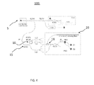
- FIG. 1 An example of how a polarization dependent optical path length shifter (PDOPS) 10, or alternatively named in the following a polarization-diverse frequency shifter (PDFS) because of the shift in the power spectrum, can be incorporated in a measurement system 100 for distributed sensing is shown in FIG. 1 .
- POPS polarization dependent optical path length shifter
- PDFS polarization-diverse frequency shifter
- a fraction of the laser light is sent to a wavelength reference cell, filled with a gas (e.g. HCN) that contains absorption lines with very well-known wavelengths in the range over which the laser is scanned.
- a gas e.g. HCN
- Part of the laser light is also sent to an auxiliary interferometer (box marked AUX), which generates a signal that is used to linearize the scan. All detector signals are digitized by a signal acquisition system; the digitized signals are sent to a computer for further processing.
- Scan linearization is required to ensure a one-to-one correspondence between scatterer position on the fiber and frequency of the detector signal.
- Linearization can be done in one of several ways.
- the signal from the auxiliary interferometer can be used to make the laser frequency depend linearly on time, by means of a feedback loop.
- Another possibility is to use the signal from the auxiliary interferometer to define the sampling moments of the signal acquisition system.
- all detector signals can be sampled at a constant rate, but the digitized signal from the auxiliary interferometer is used as input to a resampling algorithm that computes interpolated signals corresponding to a precisely linear scan.
- the PDFS 10 is incorporated in only the measurement arm or branch 17 of the interferometer system 100, so it is located after the first splitter 15, and because it needs to send two polarizations P1 and P2 through the sensing fiber 20 it is located in the measurement arm before the circulator 18 to which the sensing fiber is connected.
- the optical frequency domain reflectometry (OFDR) system 100 comprises an optical radiation source 5, e.g. a laser, capable of emitting optical radiation within a certain wavelength band, e.g. 1530 - 1550 nm, the radiation source being optically connected to a first coupling point, or splitter, 15 arranged for splitting the radiation into two parts:
- an optical radiation source e.g. a laser
- the radiation source being optically connected to a first coupling point, or splitter, 15 arranged for splitting the radiation into two parts:
- the reference path and said measurement path are optically coupled in a second coupling point 25 as shown in FIG. 1 .
- An optical detection unit 30 is capable of obtaining a signal, e.g from detectors D1 and D2, from the combined optical radiation from the reference path and the measurement path via the second coupling point 25, and accordingly obtain a scattering profile indicative of desired propertie(s) in the measurement branch 20.
- the measurement path 17 comprises a polarization dependent optical path length shifter (PDOPS, or PDFS as shown in the Figures) 10, the shifter having the function of inducing, or creating, a first polarization P1 and a second polarization P2 for the radiation in the measurement path 17, said first polarization P1 being different from said second polarization P2, and the shifter 10 further having the function that the optical path length is different for the first polarization P1 in the measurement path relative to the second polarization P2 in the measurement path 17.
- POPS polarization dependent optical path length shifter
- FIG. 2 shows embodiments (a to f) of the polarization dependent optical path length shifter (PDOPS, PDFS) 10 according to the present invention.
- POPS polarization dependent optical path length shifter
- Embodiment (a) has a 50/50 splitter as its splitting element to divide the light over the two branches.
- This splitting element does not create two orthogonal polarizations, so in this embodiment an additional component is present in one of the branches to modify the polarization, so that the polarization in this branch is orthogonal to the polarization of the other branch upon arrival at the combining element.
- a polarization controller pc (abbreviation 'pc' used in all Figures) is used that operates in transmission for this purpose.
- This polarization controller can consist of one or more loops of fiber of which the orientation can be manipulated, but can also be a (commercially available) polarization controller in which, e.g., birefringence of electro-optical materials is controlled by electrical voltages, or in which fiber birefringence is modified by external stresses.
- the light from the two branches is combined in a 50/50 combiner.
- the polarization controller is adjusted to create a polarization state that is orthogonal to the polarization from the other branch at the combiner.
- the polarization states of the two branches do not necessarily need to be orthogonal, e.g. a combination of a linear and circular state can be created, if so desired.
- the combiner has two output fibers; in a measurement system for only a single fiber only one of these output fibers would be needed and half of the light would be lost, but in systems designed for measuring multiple fibers simultaneously both outputs can be used, as is shown in FIG. 4 , which shows, as an example, a system that can measure four fibers (or four cores of a multi-core fiber).
- Embodiment (b) has a polarizing beam splitter (PBS) as its splitting component, which creates two linearly polarized orthogonal polarization states. To ensure that these polarization states contain approximately equal optical power, the polarization of the light at the input of the PBS needs to be adjusted such that this is the case.
- PBS polarizing beam splitter
- FIG. 2 a separate polarization controller is shown to perform this task, but this polarization controller may not be needed when another polarization controller is already present in the system between the laser and the PDFS, as is the case in the example system shown in FIG. 2 .
- a second PBS is used to combine the light from the two branches into a single output branch.
- Polarization maintaining (PM) fibers are used for the two branches of this embodiment, ensuring that the polarization states of the two branches at the combiner PBS are aligned with the PBS axes.
- the use of a PBS as a combiner implies that the output states are orthogonal and linearly polarized.
- Embodiment (c) is similar to embodiment (b), but in embodiment (c) standard single-mode fibers are used for the two branches. As these fibers are not guaranteed to maintain polarization, the polarization states of the two branches upon arrival at the combining PBS may no longer be linear and aligned with the polarization axes of the combiner PBS. Although the combiner PBS cleans up the polarization states of the light coming from the two branches so that linear, orthogonal, states end up in the output fiber, power may be lost. To minimize power losses, the two branches can be equipped with polarization controllers (shown dotted in the Figure).
- Embodiment (d) has a 50/50 splitter as its splitting element to divide the light over the two branches. Standard single-mode fibers are used for the two branches.
- Embodiment (d) uses a PBS as a combiner, thus ensuring that the polarization states of the two branches always result in two linearly polarized orthogonal states in the output.
- the optical power in the output states depends on the polarization states of the two branches at the combiner PBS in relation to the orientation of the PBS axes; the power transmission will be maximized when the light from the two branches is linearly polarized and parallel to the respective PBS axes.
- the two branches can be equipped with polarization controllers (shown dotted in the Figure).
- a polarization controller in only one of the branches in combination with a polarization controller before the splitter can be used (not shown in the Figure).
- the polarization controller before the splitter can be omitted if another polarization controller pc is already present in the system between the laser and the PDFS, as is the case in the example system shown in FIG. 1 .
- Embodiment (e) has a 50/50 splitter as its splitting element to divide the light over the two branches.
- the polarization is changed to an orthogonal state by a Faraday mirror attached to a circulator.
- the light from the two branches is combined in a 50/50 combiner.
- the combiner has two output fibers; in a measurement system for only a single fiber only one of these output fibers would be needed and half of the light would be lost, but in systems designed for measuring multiple fibers simultaneously both outputs can be used, as is shown in FIG. 4 .
- Embodiment (f) is similar to embodiment (e), in that it has a 50/50 splitter as its splitting element to divide the light over the two branches and that, in one of the branches, the polarization is changed to an orthogonal state by a Faraday mirror attached to a circulator. It differs from embodiment (e) in that it uses a PBS as combining element.
- the polarization state of the branch without circulator and Faraday mirror should be linear and parallel to one of the PBS axes at the combiner; the polarization state at the combiner of the branch containing the circulator and Faraday mirror is then automatically linear and parallel to the other PBS axis when the connecting fibers between the splitter and circulator, between circulator and PBS and between splitter and PBS are kept short enough to not modify the polarization state significantly
- FIG. 3 shows a schematic embodiment of an OFDR system 100 suitable for multiple sensing fibers according to the present invention.
- a primary splitter 15 first divides the light over two branches. One of the branches will be a common part of the reference arms of all interferometers, while the other branch will be a common part of the measurement arm of all interferometers. Secondary splitters, 15a and 15b, respectively are inserted in the measurement branch and the reference branch created by the first splitter 15, in order to create multiple interferometers.
- the PDFS is located in the branch that constitutes the common part of the measurement arm of all interferometers, between the first splitter and the circulators in the measurement arm of all interferometers.
- the PDFS 10 is located between the primary splitter 15 and the secondary splitter 15a, so that the two polarizations created by the PDFS are distributed to all sensing fibers 20 (only one shown), and the path length difference between the two polarization states is the same for all measurement arms. This is a desirable situation when the lengths of the sensing part of all sensing fibers are comparable.
- each PDFS for each measurement arm (not shown in a figure), in order to be able to create a path length difference of the measurement arm for the two polarizations that is adapted to the length of the sensing fiber connected to that measurement arm.
- the location of each PDFS in its respective measurement arm would be between the secondary splitter 15a and the circulator 18.
- FIG. 4 shows another schematic embodiment of an OFDR system 100 suitable for multiple sensing fibers according to the present invention.
- FIG. 4 shows another example of a setup for measuring multiple fibers.
- the setup shown in FIG. 4 is particularly suited for PDFS embodiments that have two output fibers.
- the PDFS 10 can provide part of the functionality of the secondary splitter.
- each PDFS is located in the measurement arm 17 between the primary splitter 15 and the circulator(s) 18.
- the output of the Discrete Fourier Transform is in the form of discrete bins, which can be referred to by their index number. As explained earlier, these bins correspond to positions along the fiber.
- the zero-frequency bin corresponds to the (possibly virtual) point on the fiber for which the length of the measurement branch and the reference branch are equal, as explained below.
- the fiber index range of approximately 50000-100000 containing Fiber Bragg Gratings thus corresponds to a section of fiber that is 2 to 4 meters distant from the point on the sensing fiber for which the length of the measurement arm is equal to the length of the reference arm.
- FIG. 5 shows a schematic diagram of the scattering profile of a sensing fiber with length l s , connected to the circulator via a connecting fiber with length l c .
- These could also be different parts of the same fiber, the sensing part only differing from the connection part by its intended use (when using Rayleigh scattering), or by being specially prepared (e.g. with Fiber Bragg gratings (FBG) being prepared therein).
- FBG Fiber Bragg gratings
- Discrete Fourier Transforms of the measured detector signals are used to arrive at the scattering profile of the sensing fiber. Neighboring points of a Fourier transform correspond to points on the sensing fiber that are a distance ⁇ z apart, with ⁇ z given by Eq.(2) above.
- the zero-frequency point of the computed Fourier transform corresponds to the (possibly virtual) point on the sensing fiber for which the lengths of the reference arm and the measurement arm of the interferometer are equal.
- sensing fiber of length l s attached to the circulator of the measurement system via a connecting fiber of length l c .
- connection part could again be different parts of the same fiber, the sensing part only differing from the connection part by its intended use (when using Rayleigh scattering), or by being specially prepared (e.g. with Fiber Bragg gratings being written therein).
- Backscattered light from both the sensing fiber and the connecting fiber will reach the detectors, and will end up in the computed scattering profile. No backscattered light will reach the detectors from (virtual) positions that lie before the circulator or after the physical end of the sensing fiber.
- FIG. 5 schematically shows the contributions of the connecting fiber and the sensing fiber to the computed scattering profile for the case that the equal-length point lies at a distance l 0 to the left of the start of the connecting fiber.
- the (virtual) point for which the measurement arm and reference arm have equal length lies at a distance l 0 to the left of the starting point of the connecting fiber.
- All PDFS embodiments of FIG. 2 have two optical sub-paths or branches with different lengths.
- the difference in length between the two branches of a PDFS causes the measurement arm of the interferometer to have a different length for the two polarization states created by the PDFS. Consequently, the zero-frequency point of the Fourier transform of a detector signal corresponds to one point on the sensing fiber for the first polarization state created by the PDFS, and to another point on the sensing fiber for the second polarization state, or, equivalently, any part of the sensing fiber ends up at two different positions in the computed scattering profile for the two different polarization states that are created by the PDFS.
- ⁇ PDFS The distance between these positions, expressed in meters, will be called ⁇ PDFS or ⁇ PDOPS ; the difference in length between the two branches of the PDFS (length of branch 2 minus length of branch 1) that is required to cause this shift is equal to 2 ⁇ PDFS . See Eq.(2) for the conversion factor between fiber index and position.
- the shift between the two positions should be chosen in such a manner that the data coming from the sensing fiber is not contaminated for either of the two polarization states. At the very least, this implies that the sensing fiber data for the two polarizations do not overlap in the scattering profile, giving rise to the condition ⁇ PDFS > l s
- the sensing fiber data of polarization P1 will overlap with the connecting fiber data of polarization P2.
- the scattered signal of the sensing fiber is much stronger than the Rayleigh scattering of the connecting fiber this may be acceptable, but very often the connecting fiber data also contains spurious reflections from connectors, fiber splices etc. that are strong enough to contaminate overlapping sensing fiber data.
- the signal of the sensing fiber and the connecting fiber are of comparable strength, it would be wise to increase the shift ⁇ PDFS to a larger value, to prevent any overlap: ⁇ PDFS > l s + l c
- FIG. 6 shows some examples of relative positions of the contributions of the two polarizations to the computed scattering profile.
- the shift ⁇ PDFS can be made negative, in such a manner that for all points on the sensing fiber the measurement arm for polarization P1 is longer than the reference arm, while for polarization P2 the measurement arm is shorter than the reference arm. The data for polarization P2 then appear reversed in position along the fiber.
- ⁇ PDFS two situations can be distinguished:
- FIG. 7 shows a graph with the Fourier transform (power spectrum) of a measurement with a setup according to FIG. 1 , using a PDOPS, or PDFS, according to the embodiment of FIG. 2 (a) .
- FIG. 7 shows the computed scattering profile of a single-scan measurement performed with a system incorporating the invention according to FIG. 1 , in which a PDFS according to embodiment (a) of FIG. 2 has been used.
- the sensing part of the fiber appears in the scattering profile in the (approximate) index range 55000-105000; for polarization P2 the index range is approximately 180000-230000.
- the shift ⁇ PDFS is about 125000 fiber indices, or approximately 5 meters, corresponding to 10 m length difference between the branches of the PDFS.
- FIG. 8 shows three embodiments (g to i) of a PDOPS, or PDFS, 10 where more than two output polarizations are required.
- the sensing fiber needs to be measured for only two input polarizations.
- more than two polarizations e.g. left and right circularly polarized light in addition to linearly polarized light
- FIG. 8 More polarizations are of course possible, and within reach of the skilled person once the general principle of the present invention is comprehended.
- a first single-output PDFS from FIG. 2 is followed by a second PDFS that, in one of the branches, modifies the two linear polarizations coming out of the first PDFS to left and right circularly polarized light by a polarization controller that effectively acts as a properly oriented quarter-wave plate.
- the embodiment as shown is designed for a system for the simultaneous measurement of 4 fibers, as in FIG 4 ; in case fewer fibers need to be measured the couplers to the right of the dotted vertical line can be omitted.
- FIG. 8 (h) is a concatenation of a dual-output PDFS according to the embodiment of FIG. 2 (a) and a section that acts as a quarter-wave plate in one of its branches to create left and right circularly polarized light.
- FIG 8 (i) is a 'brute-force' approach in which 4 different polarization states with differing branch lengths are created with a 1x4 splitter and separate polarization controllers as indicated with the adjacent, triple circles (it is assumed that the setup in which this embodiment is used contains a polarization controller preceding the PDFS; if this is not the case, all four branches might contain a polarization controller pc).
- the advantage of this embodiment is its flexibility - it can also be used if the desired output polarization states are not pair-wise orthogonal.
- FIG. 9 shows a flow chart of a method according to the present invention. More particulary, FIG. 9 shows a method 900 for obtaining optical frequency domain reflectometry (OFDR) data, the method comprising:
- an optical frequency domain reflectometry (OFDR) system 100 comprising a first coupling point 15 arranged for splitting radiation into two parts, so that radiation may be emitted into a reference path 16 and a measurement path 17.
- the system further comprises an optical detection unit 30 capable of obtaining a signal from the combined optical radiation from the reference path and the measurement path via a second coupling point 25.
- the measurement path 17 comprises a polarization dependent optical path length shifter (PDOPS, PDFS) 10, which may create a first polarization (P1) and a second polarization (P2) for the radiation in the measurement path, where the optical path length is different for the first and second polarizations in the measurement path.
- P1 polarization dependent optical path length shifter
- P2 polarization dependent optical path length shifter
- This may be advantageous for obtaining an improved optical frequency domain reflectometry (OFDR) system where e.g. the two measurements for input polarizations may be performed in the same scan of a radiation source.
- a computer program may be stored/distributed on a suitable medium, such as an optical storage medium or a solid-state medium supplied together with or as part of other hardware, but may also be distributed in other forms, such as via the Internet or other wired or wireless telecommunication systems. Any reference signs in the claims should not be construed as limiting the scope.
Priority Applications (6)
| Application Number | Priority Date | Filing Date | Title |
|---|---|---|---|
| EP12188515.6A EP2720388A1 (fr) | 2012-10-15 | 2012-10-15 | Système de réflectométrie de domaine de fréquence optique (OFDR) |
| JP2015536038A JP5829784B1 (ja) | 2012-10-15 | 2013-09-16 | Ofdrシステム |
| PCT/EP2013/069083 WO2014060158A1 (fr) | 2012-10-15 | 2013-09-16 | Système de réflectométrie de domaine de fréquence optique (ofdr) |
| US14/432,877 US9553664B2 (en) | 2012-10-15 | 2013-09-16 | Optical frequency domain reflectometry (OFDR) system |
| EP13770412.8A EP2907249B1 (fr) | 2012-10-15 | 2013-09-16 | Système de réflectométrie de domaine de fréquence optique (ofdr) |
| CN201380053894.4A CN104782063B (zh) | 2012-10-15 | 2013-09-16 | 光学频域反射计(ofdr)系统和用于获得光学频域反射计(ofdr)数据的方法 |
Applications Claiming Priority (1)
| Application Number | Priority Date | Filing Date | Title |
|---|---|---|---|
| EP12188515.6A EP2720388A1 (fr) | 2012-10-15 | 2012-10-15 | Système de réflectométrie de domaine de fréquence optique (OFDR) |
Publications (1)
| Publication Number | Publication Date |
|---|---|
| EP2720388A1 true EP2720388A1 (fr) | 2014-04-16 |
Family
ID=47074653
Family Applications (2)
| Application Number | Title | Priority Date | Filing Date |
|---|---|---|---|
| EP12188515.6A Withdrawn EP2720388A1 (fr) | 2012-10-15 | 2012-10-15 | Système de réflectométrie de domaine de fréquence optique (OFDR) |
| EP13770412.8A Active EP2907249B1 (fr) | 2012-10-15 | 2013-09-16 | Système de réflectométrie de domaine de fréquence optique (ofdr) |
Family Applications After (1)
| Application Number | Title | Priority Date | Filing Date |
|---|---|---|---|
| EP13770412.8A Active EP2907249B1 (fr) | 2012-10-15 | 2013-09-16 | Système de réflectométrie de domaine de fréquence optique (ofdr) |
Country Status (5)
| Country | Link |
|---|---|
| US (1) | US9553664B2 (fr) |
| EP (2) | EP2720388A1 (fr) |
| JP (1) | JP5829784B1 (fr) |
| CN (1) | CN104782063B (fr) |
| WO (1) | WO2014060158A1 (fr) |
Cited By (5)
| Publication number | Priority date | Publication date | Assignee | Title |
|---|---|---|---|---|
| WO2016075672A1 (fr) * | 2014-11-16 | 2016-05-19 | DSIT Solutions Ltd. | Réflectométrie en domaine de fréquence optique à efficacité spectrale par détection i/q |
| WO2016110467A1 (fr) * | 2015-01-08 | 2016-07-14 | Koninklijke Philips N.V. | Système de détection de forme optique, appareil médical et procédé de détection de forme optique |
| WO2016147100A1 (fr) | 2015-03-15 | 2016-09-22 | DSIT Solutions Ltd. | Réflectométrie dans le domaine fréquentiel optique à balayage de fréquence non-linéaire |
| US9632006B2 (en) | 2013-06-10 | 2017-04-25 | General Photonics Corporation | Distributed fiber bend and stress measurement for determining optical fiber reliability by multi-wavelength optical reflectometry |
| US9719883B2 (en) * | 2013-06-10 | 2017-08-01 | General Photonics Corporation | Devices and methods for characterization of distributed fiber bend and stress |
Families Citing this family (12)
| Publication number | Priority date | Publication date | Assignee | Title |
|---|---|---|---|---|
| CN105823621A (zh) * | 2016-03-25 | 2016-08-03 | 江苏骏龙电力科技股份有限公司 | 一种基于便携式的光频域反射仪 |
| CN105698871B (zh) * | 2016-03-29 | 2018-08-21 | 天津大学 | 基于光频域反射的分布式应变温度同时测量装置及方法 |
| CN108603977B (zh) | 2016-05-11 | 2020-08-07 | 直观外科手术操作公司 | 具有用于安全性的冗余纤芯的多纤芯光学纤维 |
| WO2018063546A1 (fr) * | 2016-09-27 | 2018-04-05 | Intuive Surgical Operations, Inc. | Ensembles micro-optiques et systèmes d'interrogation optique |
| KR101844031B1 (ko) | 2017-06-13 | 2018-05-14 | 한국광기술원 | 광주파수 영역 반사측정 시스템 및 측정방법 |
| CN107576341B (zh) * | 2017-08-09 | 2021-06-04 | 武汉昊衡科技有限公司 | Ofdr中消除偏振衰落的装置和方法 |
| WO2020117457A1 (fr) | 2018-12-04 | 2020-06-11 | Ofs Fitel, Llc | Capteur distribué haute résolution utilisant une fibre optique à coeur décalé |
| US11923898B2 (en) | 2019-04-15 | 2024-03-05 | Luna Innovations Incorporated | Calculation of distributed birefringence and polarization mode dispersion from waveguide scatter with full polarization state optical frequency domain reflectometry |
| CN112197878A (zh) * | 2019-07-08 | 2021-01-08 | 上海交通大学 | 基于光频域反射仪的高精度光波长检测方法及系统 |
| CN111579049B (zh) * | 2020-05-12 | 2021-04-20 | 山东大学 | 一种基于单次测量的ofdr系统振动检测方法 |
| CN111735527B (zh) * | 2020-06-01 | 2022-03-29 | 哈尔滨工业大学 | 基于时域相位计算的光纤分布式振动传感方法 |
| CN111947782A (zh) * | 2020-07-07 | 2020-11-17 | 中国南方电网有限责任公司超高压输电公司昆明局 | 一种自适应偏振衰落抑制的特高压直流控制保护系统otdr装置 |
Citations (5)
| Publication number | Priority date | Publication date | Assignee | Title |
|---|---|---|---|---|
| US20070086017A1 (en) * | 2005-10-07 | 2007-04-19 | Bioptigen, Inc. | Imaging Systems Using Unpolarized Light And Related Methods And Controllers |
| WO2007149230A2 (fr) * | 2006-06-16 | 2007-12-27 | Luna Innovations Incorporated | Discrimination de l'effort et de la tempÉrature distribuÉs dans une fibre À maintien de la polarisation |
| EP2128588A1 (fr) * | 2007-02-28 | 2009-12-02 | Nippon Telegraph and Telephone Corporation | Procédé et dispositif de mesure par réfractométrie optique |
| US20110109898A1 (en) | 2009-09-18 | 2011-05-12 | Luna Innovations Incorporated | Optical position and/or shape sensing |
| US20120194823A1 (en) * | 2011-01-28 | 2012-08-02 | The Regents Of The University Of Colorado, A Body Corporate | Spectral Phase Analysis For Precision Ranging |
Family Cites Families (10)
| Publication number | Priority date | Publication date | Assignee | Title |
|---|---|---|---|---|
| US6856400B1 (en) | 2000-12-14 | 2005-02-15 | Luna Technologies | Apparatus and method for the complete characterization of optical devices including loss, birefringence and dispersion effects |
| ATE376665T1 (de) * | 2003-02-06 | 2007-11-15 | Exfo Electro Optical Eng Inc | Verfahren und apparat zur messung der polarisationsmodendispersion |
| ATE350656T1 (de) | 2003-02-21 | 2007-01-15 | Thorlabs Inc | Vorrichtung und verfahren zur bestimmung der chromatischen dispersion von optischen komponenten |
| EP1639331B1 (fr) * | 2003-06-04 | 2016-08-24 | Samsung Electronics Co., Ltd. | Mesures de l'inhomogeneite optique et d'autres proprietes dans des substances au moyen de modes de propagation de la lumiere |
| US6943881B2 (en) | 2003-06-04 | 2005-09-13 | Tomophase Corporation | Measurements of optical inhomogeneity and other properties in substances using propagation modes of light |
| US8004686B2 (en) * | 2004-12-14 | 2011-08-23 | Luna Innovations Inc. | Compensating for time varying phase changes in interferometric measurements |
| WO2009107838A1 (fr) * | 2008-02-29 | 2009-09-03 | 株式会社フジクラ | Dispositif de mesure d'une quantité physique par mesure de la réflexion de la gamme de fréquence optique et procédé de mesure de la température et des contraintes à l'aide dudit dispositif |
| JP5645374B2 (ja) * | 2009-06-30 | 2014-12-24 | 日本オクラロ株式会社 | 干渉計、復調器及び光通信モジュール |
| JP5233953B2 (ja) * | 2009-10-27 | 2013-07-10 | 富士通オプティカルコンポーネンツ株式会社 | 遅延干渉計、受信機、及び遅延干渉方法 |
| EP2721434B1 (fr) * | 2011-06-14 | 2021-05-05 | Intuitive Surgical Operations, Inc. | Mise en coïncidence d'âmes dans des systèmes de détection de fibres optiques multi-âmes |
-
2012
- 2012-10-15 EP EP12188515.6A patent/EP2720388A1/fr not_active Withdrawn
-
2013
- 2013-09-16 CN CN201380053894.4A patent/CN104782063B/zh active Active
- 2013-09-16 JP JP2015536038A patent/JP5829784B1/ja active Active
- 2013-09-16 EP EP13770412.8A patent/EP2907249B1/fr active Active
- 2013-09-16 US US14/432,877 patent/US9553664B2/en active Active
- 2013-09-16 WO PCT/EP2013/069083 patent/WO2014060158A1/fr active Application Filing
Patent Citations (5)
| Publication number | Priority date | Publication date | Assignee | Title |
|---|---|---|---|---|
| US20070086017A1 (en) * | 2005-10-07 | 2007-04-19 | Bioptigen, Inc. | Imaging Systems Using Unpolarized Light And Related Methods And Controllers |
| WO2007149230A2 (fr) * | 2006-06-16 | 2007-12-27 | Luna Innovations Incorporated | Discrimination de l'effort et de la tempÉrature distribuÉs dans une fibre À maintien de la polarisation |
| EP2128588A1 (fr) * | 2007-02-28 | 2009-12-02 | Nippon Telegraph and Telephone Corporation | Procédé et dispositif de mesure par réfractométrie optique |
| US20110109898A1 (en) | 2009-09-18 | 2011-05-12 | Luna Innovations Incorporated | Optical position and/or shape sensing |
| US20120194823A1 (en) * | 2011-01-28 | 2012-08-02 | The Regents Of The University Of Colorado, A Body Corporate | Spectral Phase Analysis For Precision Ranging |
Cited By (9)
| Publication number | Priority date | Publication date | Assignee | Title |
|---|---|---|---|---|
| US9632006B2 (en) | 2013-06-10 | 2017-04-25 | General Photonics Corporation | Distributed fiber bend and stress measurement for determining optical fiber reliability by multi-wavelength optical reflectometry |
| US9719883B2 (en) * | 2013-06-10 | 2017-08-01 | General Photonics Corporation | Devices and methods for characterization of distributed fiber bend and stress |
| US9829410B2 (en) | 2013-06-10 | 2017-11-28 | General Photonics Corporation | Distributed fiber bend and stress measurement for determining optical fiber reliability by multi-wavelength optical reflectometry |
| US10324002B2 (en) | 2013-06-10 | 2019-06-18 | General Photonics Corporation | Devices and methods for characterization of distributed fiber bend and stress |
| WO2016075672A1 (fr) * | 2014-11-16 | 2016-05-19 | DSIT Solutions Ltd. | Réflectométrie en domaine de fréquence optique à efficacité spectrale par détection i/q |
| WO2016110467A1 (fr) * | 2015-01-08 | 2016-07-14 | Koninklijke Philips N.V. | Système de détection de forme optique, appareil médical et procédé de détection de forme optique |
| WO2016147100A1 (fr) | 2015-03-15 | 2016-09-22 | DSIT Solutions Ltd. | Réflectométrie dans le domaine fréquentiel optique à balayage de fréquence non-linéaire |
| EP3271702A4 (fr) * | 2015-03-15 | 2018-11-07 | Dsit Solutions Ltd. | Réflectométrie dans le domaine fréquentiel optique à balayage de fréquence non-linéaire |
| US10330594B2 (en) | 2015-03-15 | 2019-06-25 | DSIT Solutions Ltd. | Non-linear frequency scan optical frequency-domain reflectometry having a processor to estimate a backscattering profile of an optical fiber by applying a predefined function to a beat signal |
Also Published As
| Publication number | Publication date |
|---|---|
| US9553664B2 (en) | 2017-01-24 |
| EP2907249B1 (fr) | 2016-08-24 |
| US20150263804A1 (en) | 2015-09-17 |
| CN104782063B (zh) | 2016-08-24 |
| WO2014060158A1 (fr) | 2014-04-24 |
| EP2907249A1 (fr) | 2015-08-19 |
| JP2015536445A (ja) | 2015-12-21 |
| JP5829784B1 (ja) | 2015-12-09 |
| CN104782063A (zh) | 2015-07-15 |
Similar Documents
| Publication | Publication Date | Title |
|---|---|---|
| EP2907249B1 (fr) | Système de réflectométrie de domaine de fréquence optique (ofdr) | |
| CA2695587C (fr) | Appareil de mesure de quantite physique utilisant la reflectometrie du domaine de frequences optiques et methode de mesure de la temperature et des contraintes a l'aide de l'appareil | |
| EP2577221B1 (fr) | Mesure interférométrique avec suppression de la diaphonie | |
| JP4420982B2 (ja) | 光周波数領域反射測定方式の物理量計測装置、および、これを用いた温度と歪みの同時計測方法 | |
| Liang et al. | A comprehensive study of optical frequency domain reflectometry | |
| CN103196584B (zh) | 测量光纤中温度和应力的方法、以及布里渊光时域反射仪 | |
| WO2006099056A2 (fr) | Calcul de la birefringence dans un guide d'onde en fonction de la diffusion de rayleigh | |
| CN101871788A (zh) | 测量保偏光纤和双折射介质的分布式偏振串扰方法及装置 | |
| US20160266005A1 (en) | Methods and apparatus for simultaneous optical parameter measurements | |
| WO2014072845A1 (fr) | Système de réflectométrie en domaine de fréquences optiques (ofdr) ayant de multiples fibres par chaîne de détection | |
| WO2004005973A2 (fr) | Detection de la diversite de polarisation sans separateur de faisceau polarisant | |
| US10363101B2 (en) | Optical shape sensing system, medical apparatus and method for optical shape sensing | |
| Barkov et al. | Modelling of polarised optical frequency domain reflectometry of axially twisted anisotropic optical fibres | |
| Lucki et al. | Fiber Optic and Free Space Michelson Interferometer—Principle and Practice | |
| Liehr et al. | A novel fiber optic technique for quasi-distributed and dynamic measurement of length change and refractive index | |
| KR20190042218A (ko) | 편광유지광섬유를 이용한 광온도 측정 장치 | |
| Tang et al. | Distributed optical fiber fusion sensing system based on dual light source and pulse precision delay technology | |
| Chatterjee et al. | Multipoint Monitoring of Instantaneous Amplitude, Frequency, Phase and Sequence of Vibrations Using Concatenated Modal Interferometers | |
| Wang et al. | Research on polarization control in the long distance fiber-optic sensing | |
| Waagaard et al. | Spatial characterization of strong fiber Bragg gratings | |
| Ding et al. | Monitoring optical fiber sensor networks by optical frequency-domain reflectometry | |
| Rogers et al. | Novel methods for distributed optical fiber sensing | |
| JP2021043050A (ja) | 光学センサおよび物理量測定装置 | |
| Liehr et al. | A dynamic fiber optic strain and power change sensor |
Legal Events
| Date | Code | Title | Description |
|---|---|---|---|
| PUAI | Public reference made under article 153(3) epc to a published international application that has entered the european phase |
Free format text: ORIGINAL CODE: 0009012 |
|
| AK | Designated contracting states |
Kind code of ref document: A1 Designated state(s): AL AT BE BG CH CY CZ DE DK EE ES FI FR GB GR HR HU IE IS IT LI LT LU LV MC MK MT NL NO PL PT RO RS SE SI SK SM TR |
|
| AX | Request for extension of the european patent |
Extension state: BA ME |
|
| STAA | Information on the status of an ep patent application or granted ep patent |
Free format text: STATUS: THE APPLICATION IS DEEMED TO BE WITHDRAWN |
|
| 18D | Application deemed to be withdrawn |
Effective date: 20141017 |