EP3563119B1 - Procédés et appareil pour déterminer un ou plusieurs paramètres de forme à l'aide d'une fibre de détection ayant un coeur unique à multiples modes de propagation de lumière - Google Patents
Procédés et appareil pour déterminer un ou plusieurs paramètres de forme à l'aide d'une fibre de détection ayant un coeur unique à multiples modes de propagation de lumière Download PDFInfo
- Publication number
- EP3563119B1 EP3563119B1 EP17886412.0A EP17886412A EP3563119B1 EP 3563119 B1 EP3563119 B1 EP 3563119B1 EP 17886412 A EP17886412 A EP 17886412A EP 3563119 B1 EP3563119 B1 EP 3563119B1
- Authority
- EP
- European Patent Office
- Prior art keywords
- core
- fiber
- cross
- multimode core
- light
- Prior art date
- Legal status (The legal status is an assumption and is not a legal conclusion. Google has not performed a legal analysis and makes no representation as to the accuracy of the status listed.)
- Active
Links
- 239000000835 fiber Substances 0.000 title claims description 245
- 230000001902 propagating effect Effects 0.000 title claims description 46
- 238000000034 method Methods 0.000 title claims description 30
- 238000010168 coupling process Methods 0.000 claims description 75
- 238000005859 coupling reaction Methods 0.000 claims description 75
- 230000008878 coupling Effects 0.000 claims description 73
- 238000005259 measurement Methods 0.000 claims description 46
- 239000011159 matrix material Substances 0.000 claims description 32
- 238000006880 cross-coupling reaction Methods 0.000 claims description 29
- 230000003287 optical effect Effects 0.000 claims description 25
- 230000006870 function Effects 0.000 claims description 24
- 238000012545 processing Methods 0.000 claims description 21
- 230000008859 change Effects 0.000 claims description 13
- 230000035945 sensitivity Effects 0.000 claims description 12
- 238000000354 decomposition reaction Methods 0.000 claims description 11
- 230000001934 delay Effects 0.000 claims description 11
- 239000000523 sample Substances 0.000 claims description 9
- 230000008569 process Effects 0.000 claims description 7
- 238000002168 optical frequency-domain reflectometry Methods 0.000 description 20
- 230000004044 response Effects 0.000 description 12
- 239000013307 optical fiber Substances 0.000 description 11
- 238000005452 bending Methods 0.000 description 7
- 238000006243 chemical reaction Methods 0.000 description 6
- 238000005516 engineering process Methods 0.000 description 5
- 230000010287 polarization Effects 0.000 description 5
- 238000005253 cladding Methods 0.000 description 4
- 238000012937 correction Methods 0.000 description 4
- 238000012952 Resampling Methods 0.000 description 3
- 230000035508 accumulation Effects 0.000 description 3
- 238000009825 accumulation Methods 0.000 description 3
- 238000013461 design Methods 0.000 description 3
- 238000010586 diagram Methods 0.000 description 3
- 230000008901 benefit Effects 0.000 description 2
- 150000001875 compounds Chemical class 0.000 description 2
- 230000001066 destructive effect Effects 0.000 description 2
- 238000001514 detection method Methods 0.000 description 2
- 230000000694 effects Effects 0.000 description 2
- 230000005684 electric field Effects 0.000 description 2
- 229910052732 germanium Inorganic materials 0.000 description 2
- GNPVGFCGXDBREM-UHFFFAOYSA-N germanium atom Chemical compound [Ge] GNPVGFCGXDBREM-UHFFFAOYSA-N 0.000 description 2
- 230000003993 interaction Effects 0.000 description 2
- 238000004519 manufacturing process Methods 0.000 description 2
- 238000013507 mapping Methods 0.000 description 2
- 239000007787 solid Substances 0.000 description 2
- 238000001228 spectrum Methods 0.000 description 2
- 101710121003 Oxygen-evolving enhancer protein 3, chloroplastic Proteins 0.000 description 1
- 238000013459 approach Methods 0.000 description 1
- 238000004364 calculation method Methods 0.000 description 1
- 238000004891 communication Methods 0.000 description 1
- 230000006835 compression Effects 0.000 description 1
- 238000007906 compression Methods 0.000 description 1
- 238000010276 construction Methods 0.000 description 1
- 238000009826 distribution Methods 0.000 description 1
- -1 e.g. Substances 0.000 description 1
- 238000000605 extraction Methods 0.000 description 1
- 238000003384 imaging method Methods 0.000 description 1
- 238000002955 isolation Methods 0.000 description 1
- 230000007246 mechanism Effects 0.000 description 1
- ONCZDRURRATYFI-QTCHDTBASA-N methyl (2z)-2-methoxyimino-2-[2-[[(e)-1-[3-(trifluoromethyl)phenyl]ethylideneamino]oxymethyl]phenyl]acetate Chemical compound CO\N=C(/C(=O)OC)C1=CC=CC=C1CO\N=C(/C)C1=CC=CC(C(F)(F)F)=C1 ONCZDRURRATYFI-QTCHDTBASA-N 0.000 description 1
- 230000007935 neutral effect Effects 0.000 description 1
- 230000000737 periodic effect Effects 0.000 description 1
- 230000005624 perturbation theories Effects 0.000 description 1
- 230000000644 propagated effect Effects 0.000 description 1
- 238000005070 sampling Methods 0.000 description 1
- 238000004088 simulation Methods 0.000 description 1
- 230000009466 transformation Effects 0.000 description 1
- 238000000411 transmission spectrum Methods 0.000 description 1
Images


Classifications
-
- G—PHYSICS
- G01—MEASURING; TESTING
- G01D—MEASURING NOT SPECIALLY ADAPTED FOR A SPECIFIC VARIABLE; ARRANGEMENTS FOR MEASURING TWO OR MORE VARIABLES NOT COVERED IN A SINGLE OTHER SUBCLASS; TARIFF METERING APPARATUS; MEASURING OR TESTING NOT OTHERWISE PROVIDED FOR
- G01D5/00—Mechanical means for transferring the output of a sensing member; Means for converting the output of a sensing member to another variable where the form or nature of the sensing member does not constrain the means for converting; Transducers not specially adapted for a specific variable
- G01D5/26—Mechanical means for transferring the output of a sensing member; Means for converting the output of a sensing member to another variable where the form or nature of the sensing member does not constrain the means for converting; Transducers not specially adapted for a specific variable characterised by optical transfer means, i.e. using infrared, visible, or ultraviolet light
- G01D5/32—Mechanical means for transferring the output of a sensing member; Means for converting the output of a sensing member to another variable where the form or nature of the sensing member does not constrain the means for converting; Transducers not specially adapted for a specific variable characterised by optical transfer means, i.e. using infrared, visible, or ultraviolet light with attenuation or whole or partial obturation of beams of light
- G01D5/34—Mechanical means for transferring the output of a sensing member; Means for converting the output of a sensing member to another variable where the form or nature of the sensing member does not constrain the means for converting; Transducers not specially adapted for a specific variable characterised by optical transfer means, i.e. using infrared, visible, or ultraviolet light with attenuation or whole or partial obturation of beams of light the beams of light being detected by photocells
- G01D5/353—Mechanical means for transferring the output of a sensing member; Means for converting the output of a sensing member to another variable where the form or nature of the sensing member does not constrain the means for converting; Transducers not specially adapted for a specific variable characterised by optical transfer means, i.e. using infrared, visible, or ultraviolet light with attenuation or whole or partial obturation of beams of light the beams of light being detected by photocells influencing the transmission properties of an optical fibre
- G01D5/35306—Mechanical means for transferring the output of a sensing member; Means for converting the output of a sensing member to another variable where the form or nature of the sensing member does not constrain the means for converting; Transducers not specially adapted for a specific variable characterised by optical transfer means, i.e. using infrared, visible, or ultraviolet light with attenuation or whole or partial obturation of beams of light the beams of light being detected by photocells influencing the transmission properties of an optical fibre using an interferometer arrangement
- G01D5/35309—Mechanical means for transferring the output of a sensing member; Means for converting the output of a sensing member to another variable where the form or nature of the sensing member does not constrain the means for converting; Transducers not specially adapted for a specific variable characterised by optical transfer means, i.e. using infrared, visible, or ultraviolet light with attenuation or whole or partial obturation of beams of light the beams of light being detected by photocells influencing the transmission properties of an optical fibre using an interferometer arrangement using multiple waves interferometer
- G01D5/35316—Mechanical means for transferring the output of a sensing member; Means for converting the output of a sensing member to another variable where the form or nature of the sensing member does not constrain the means for converting; Transducers not specially adapted for a specific variable characterised by optical transfer means, i.e. using infrared, visible, or ultraviolet light with attenuation or whole or partial obturation of beams of light the beams of light being detected by photocells influencing the transmission properties of an optical fibre using an interferometer arrangement using multiple waves interferometer using a Bragg gratings
-
- G—PHYSICS
- G01—MEASURING; TESTING
- G01B—MEASURING LENGTH, THICKNESS OR SIMILAR LINEAR DIMENSIONS; MEASURING ANGLES; MEASURING AREAS; MEASURING IRREGULARITIES OF SURFACES OR CONTOURS
- G01B11/00—Measuring arrangements characterised by the use of optical techniques
- G01B11/16—Measuring arrangements characterised by the use of optical techniques for measuring the deformation in a solid, e.g. optical strain gauge
- G01B11/18—Measuring arrangements characterised by the use of optical techniques for measuring the deformation in a solid, e.g. optical strain gauge using photoelastic elements
-
- G—PHYSICS
- G01—MEASURING; TESTING
- G01B—MEASURING LENGTH, THICKNESS OR SIMILAR LINEAR DIMENSIONS; MEASURING ANGLES; MEASURING AREAS; MEASURING IRREGULARITIES OF SURFACES OR CONTOURS
- G01B11/00—Measuring arrangements characterised by the use of optical techniques
- G01B11/24—Measuring arrangements characterised by the use of optical techniques for measuring contours or curvatures
-
- G—PHYSICS
- G01—MEASURING; TESTING
- G01D—MEASURING NOT SPECIALLY ADAPTED FOR A SPECIFIC VARIABLE; ARRANGEMENTS FOR MEASURING TWO OR MORE VARIABLES NOT COVERED IN A SINGLE OTHER SUBCLASS; TARIFF METERING APPARATUS; MEASURING OR TESTING NOT OTHERWISE PROVIDED FOR
- G01D5/00—Mechanical means for transferring the output of a sensing member; Means for converting the output of a sensing member to another variable where the form or nature of the sensing member does not constrain the means for converting; Transducers not specially adapted for a specific variable
- G01D5/26—Mechanical means for transferring the output of a sensing member; Means for converting the output of a sensing member to another variable where the form or nature of the sensing member does not constrain the means for converting; Transducers not specially adapted for a specific variable characterised by optical transfer means, i.e. using infrared, visible, or ultraviolet light
- G01D5/32—Mechanical means for transferring the output of a sensing member; Means for converting the output of a sensing member to another variable where the form or nature of the sensing member does not constrain the means for converting; Transducers not specially adapted for a specific variable characterised by optical transfer means, i.e. using infrared, visible, or ultraviolet light with attenuation or whole or partial obturation of beams of light
- G01D5/34—Mechanical means for transferring the output of a sensing member; Means for converting the output of a sensing member to another variable where the form or nature of the sensing member does not constrain the means for converting; Transducers not specially adapted for a specific variable characterised by optical transfer means, i.e. using infrared, visible, or ultraviolet light with attenuation or whole or partial obturation of beams of light the beams of light being detected by photocells
- G01D5/353—Mechanical means for transferring the output of a sensing member; Means for converting the output of a sensing member to another variable where the form or nature of the sensing member does not constrain the means for converting; Transducers not specially adapted for a specific variable characterised by optical transfer means, i.e. using infrared, visible, or ultraviolet light with attenuation or whole or partial obturation of beams of light the beams of light being detected by photocells influencing the transmission properties of an optical fibre
- G01D5/35306—Mechanical means for transferring the output of a sensing member; Means for converting the output of a sensing member to another variable where the form or nature of the sensing member does not constrain the means for converting; Transducers not specially adapted for a specific variable characterised by optical transfer means, i.e. using infrared, visible, or ultraviolet light with attenuation or whole or partial obturation of beams of light the beams of light being detected by photocells influencing the transmission properties of an optical fibre using an interferometer arrangement
-
- G—PHYSICS
- G01—MEASURING; TESTING
- G01D—MEASURING NOT SPECIALLY ADAPTED FOR A SPECIFIC VARIABLE; ARRANGEMENTS FOR MEASURING TWO OR MORE VARIABLES NOT COVERED IN A SINGLE OTHER SUBCLASS; TARIFF METERING APPARATUS; MEASURING OR TESTING NOT OTHERWISE PROVIDED FOR
- G01D5/00—Mechanical means for transferring the output of a sensing member; Means for converting the output of a sensing member to another variable where the form or nature of the sensing member does not constrain the means for converting; Transducers not specially adapted for a specific variable
- G01D5/26—Mechanical means for transferring the output of a sensing member; Means for converting the output of a sensing member to another variable where the form or nature of the sensing member does not constrain the means for converting; Transducers not specially adapted for a specific variable characterised by optical transfer means, i.e. using infrared, visible, or ultraviolet light
- G01D5/32—Mechanical means for transferring the output of a sensing member; Means for converting the output of a sensing member to another variable where the form or nature of the sensing member does not constrain the means for converting; Transducers not specially adapted for a specific variable characterised by optical transfer means, i.e. using infrared, visible, or ultraviolet light with attenuation or whole or partial obturation of beams of light
- G01D5/34—Mechanical means for transferring the output of a sensing member; Means for converting the output of a sensing member to another variable where the form or nature of the sensing member does not constrain the means for converting; Transducers not specially adapted for a specific variable characterised by optical transfer means, i.e. using infrared, visible, or ultraviolet light with attenuation or whole or partial obturation of beams of light the beams of light being detected by photocells
- G01D5/353—Mechanical means for transferring the output of a sensing member; Means for converting the output of a sensing member to another variable where the form or nature of the sensing member does not constrain the means for converting; Transducers not specially adapted for a specific variable characterised by optical transfer means, i.e. using infrared, visible, or ultraviolet light with attenuation or whole or partial obturation of beams of light the beams of light being detected by photocells influencing the transmission properties of an optical fibre
- G01D5/35338—Mechanical means for transferring the output of a sensing member; Means for converting the output of a sensing member to another variable where the form or nature of the sensing member does not constrain the means for converting; Transducers not specially adapted for a specific variable characterised by optical transfer means, i.e. using infrared, visible, or ultraviolet light with attenuation or whole or partial obturation of beams of light the beams of light being detected by photocells influencing the transmission properties of an optical fibre using other arrangements than interferometer arrangements
- G01D5/35354—Sensor working in reflection
-
- G—PHYSICS
- G01—MEASURING; TESTING
- G01D—MEASURING NOT SPECIALLY ADAPTED FOR A SPECIFIC VARIABLE; ARRANGEMENTS FOR MEASURING TWO OR MORE VARIABLES NOT COVERED IN A SINGLE OTHER SUBCLASS; TARIFF METERING APPARATUS; MEASURING OR TESTING NOT OTHERWISE PROVIDED FOR
- G01D5/00—Mechanical means for transferring the output of a sensing member; Means for converting the output of a sensing member to another variable where the form or nature of the sensing member does not constrain the means for converting; Transducers not specially adapted for a specific variable
- G01D5/26—Mechanical means for transferring the output of a sensing member; Means for converting the output of a sensing member to another variable where the form or nature of the sensing member does not constrain the means for converting; Transducers not specially adapted for a specific variable characterised by optical transfer means, i.e. using infrared, visible, or ultraviolet light
- G01D5/32—Mechanical means for transferring the output of a sensing member; Means for converting the output of a sensing member to another variable where the form or nature of the sensing member does not constrain the means for converting; Transducers not specially adapted for a specific variable characterised by optical transfer means, i.e. using infrared, visible, or ultraviolet light with attenuation or whole or partial obturation of beams of light
- G01D5/34—Mechanical means for transferring the output of a sensing member; Means for converting the output of a sensing member to another variable where the form or nature of the sensing member does not constrain the means for converting; Transducers not specially adapted for a specific variable characterised by optical transfer means, i.e. using infrared, visible, or ultraviolet light with attenuation or whole or partial obturation of beams of light the beams of light being detected by photocells
- G01D5/353—Mechanical means for transferring the output of a sensing member; Means for converting the output of a sensing member to another variable where the form or nature of the sensing member does not constrain the means for converting; Transducers not specially adapted for a specific variable characterised by optical transfer means, i.e. using infrared, visible, or ultraviolet light with attenuation or whole or partial obturation of beams of light the beams of light being detected by photocells influencing the transmission properties of an optical fibre
- G01D5/3537—Optical fibre sensor using a particular arrangement of the optical fibre itself
- G01D5/3538—Optical fibre sensor using a particular arrangement of the optical fibre itself using a particular type of fiber, e.g. fibre with several cores, PANDA fiber, fiber with an elliptic core or the like
-
- G—PHYSICS
- G01—MEASURING; TESTING
- G01J—MEASUREMENT OF INTENSITY, VELOCITY, SPECTRAL CONTENT, POLARISATION, PHASE OR PULSE CHARACTERISTICS OF INFRARED, VISIBLE OR ULTRAVIOLET LIGHT; COLORIMETRY; RADIATION PYROMETRY
- G01J1/00—Photometry, e.g. photographic exposure meter
- G01J1/02—Details
- G01J1/04—Optical or mechanical part supplementary adjustable parts
- G01J1/0407—Optical elements not provided otherwise, e.g. manifolds, windows, holograms, gratings
- G01J1/0425—Optical elements not provided otherwise, e.g. manifolds, windows, holograms, gratings using optical fibers
-
- G—PHYSICS
- G01—MEASURING; TESTING
- G01M—TESTING STATIC OR DYNAMIC BALANCE OF MACHINES OR STRUCTURES; TESTING OF STRUCTURES OR APPARATUS, NOT OTHERWISE PROVIDED FOR
- G01M11/00—Testing of optical apparatus; Testing structures by optical methods not otherwise provided for
- G01M11/08—Testing mechanical properties
- G01M11/083—Testing mechanical properties by using an optical fiber in contact with the device under test [DUT]
- G01M11/085—Testing mechanical properties by using an optical fiber in contact with the device under test [DUT] the optical fiber being on or near the surface of the DUT
-
- G—PHYSICS
- G02—OPTICS
- G02B—OPTICAL ELEMENTS, SYSTEMS OR APPARATUS
- G02B6/00—Light guides; Structural details of arrangements comprising light guides and other optical elements, e.g. couplings
- G02B6/02—Optical fibres with cladding with or without a coating
- G02B6/02042—Multicore optical fibres
-
- G—PHYSICS
- G02—OPTICS
- G02B—OPTICAL ELEMENTS, SYSTEMS OR APPARATUS
- G02B6/00—Light guides; Structural details of arrangements comprising light guides and other optical elements, e.g. couplings
- G02B6/02—Optical fibres with cladding with or without a coating
- G02B6/02047—Dual mode fibre
-
- G—PHYSICS
- G02—OPTICS
- G02B—OPTICAL ELEMENTS, SYSTEMS OR APPARATUS
- G02B6/00—Light guides; Structural details of arrangements comprising light guides and other optical elements, e.g. couplings
- G02B6/02—Optical fibres with cladding with or without a coating
- G02B6/02057—Optical fibres with cladding with or without a coating comprising gratings
- G02B6/02076—Refractive index modulation gratings, e.g. Bragg gratings
- G02B6/0208—Refractive index modulation gratings, e.g. Bragg gratings characterised by their structure, wavelength response
- G02B6/02085—Refractive index modulation gratings, e.g. Bragg gratings characterised by their structure, wavelength response characterised by the grating profile, e.g. chirped, apodised, tilted, helical
-
- G—PHYSICS
- G02—OPTICS
- G02B—OPTICAL ELEMENTS, SYSTEMS OR APPARATUS
- G02B6/00—Light guides; Structural details of arrangements comprising light guides and other optical elements, e.g. couplings
- G02B6/02—Optical fibres with cladding with or without a coating
- G02B6/02057—Optical fibres with cladding with or without a coating comprising gratings
- G02B6/02076—Refractive index modulation gratings, e.g. Bragg gratings
- G02B6/02123—Refractive index modulation gratings, e.g. Bragg gratings characterised by the method of manufacture of the grating
- G02B6/02142—Refractive index modulation gratings, e.g. Bragg gratings characterised by the method of manufacture of the grating based on illuminating or irradiating an amplitude mask, i.e. a mask having a repetitive intensity modulating pattern
-
- G—PHYSICS
- G02—OPTICS
- G02B—OPTICAL ELEMENTS, SYSTEMS OR APPARATUS
- G02B6/00—Light guides; Structural details of arrangements comprising light guides and other optical elements, e.g. couplings
- G02B6/02—Optical fibres with cladding with or without a coating
- G02B6/028—Optical fibres with cladding with or without a coating with core or cladding having graded refractive index
- G02B6/0288—Multimode fibre, e.g. graded index core for compensating modal dispersion
Definitions
- the technology described in this application relates to optical interrogation system measurements used for fiber optic shape and other sensing applications.
- Optical strain sensing is a technology useful for measuring physical deformation of a waveguide caused by, for example, the change in tension, compression, or temperature of an optical fiber. Measuring the shape of an optical fiber using multiple single mode cores to determine parameters including pitch, yaw, twist, and strain has been demonstrated. Shape is the position or orientation of the fiber in three dimensions.
- a continuous measure of strain along the length of a core can be derived by interpreting the optical response of the core using swept wavelength inteferometery typically in the form of Optical Frequency Domain Reflectometry (OFDR) measurements. With knowledge of the relative positions of the cores along the length of the fiber, these independent strain signals may be combined to gain a measure of the strain profile applied to the multi-core optical fiber.
- OFDR Optical Frequency Domain Reflectometry
- the strain profile of the fiber refers to the measure of applied bend strain, twist strain, and/or axial strain along the length of the fiber at a high (e.g., less than 50 micrometers) sample resolution.
- a non-limiting example application is robotic arms used in surgical or other environments.
- Previous patents have described OFDR-based shape sensing with multiple single mode cores (e.g., see U.S. patents 7,781,724 and 8,773,650 ).
- Fibers with multiple single mode cores are difficult and costly to manufacture. Cost is further increased when multi-core fibers must be spun or helically-twisted during manufacture, which is the case for prior multi-core shape sensing fiber. If a single core, unspun fiber could be used to sense shape, then the cost of the fiber sensor could be significantly reduced. For example, mass produced, standard telecom fiber that has single cores and is unspun sells for pennies per meter. But there are several technological challenges (described below) that must be addressed and overcome in order for a single core, multiple mode fiber to sense shape.
- U.S. Pat. Pub 2011/0090486 discloses, in certain variation, fiber shape sensing or measuring systems, devices, and methods, which allow for measurement of three dimensional bending as well as twist measurements of various fibers, e.g., optical fibers and fiber optic probes of various sizes.
- the systems are designed to take advantage of unique light guiding properties of optical fibers and various fiber gratings.
- the two groups of cladding mode resonances in the reflection spectrum respond differentially to bending, which allows for the unique determination of the magnitude and orientation of the bend plane (i.e. with a ⁇ 180 degree uncertainty). Bending responses ranging from -0.33 to + 0.21 dB/m-1 (depending on orientation) are experimentally demonstrated with bending from 0 to 3.03 m-1.
- the strain is obtained directly by the shift of the TFBG Bragg wavelengths with a sensitivity of 1.06 pm/ ⁇ .
- Example embodiments include an optical interrogation system and method for probing a sensing fiber having a single core, where the single core has multiple light propagating modes.
- the system includes interferometric apparatus to probe a single multimode core of the sensing fiber over a range of predetermined wavelengths of light, the single multimode core having at least three light propagating modes, the interferometric apparatus comprising at least three interferometers including at least three reference branches and at least three measurement branches, the at least three measurement branches having different optical delays and comprising an array of associated single-core-single-mode detecting fibers, each single-core-single-mode detecting fiber to couple light in a light propagating mode of the at least three light propagating modes, the interferometric apparatus further comprising acquisition circuitry to detect measurement interferometric data associated with reflected light coupled from the at least three light propagating modes of the single multimode core back into the array of single-core-single-mode fibers for each predetermined wavelength in the range.
- Data processing circuitry processes the measurement interferometric data to determine modal cross coupling coefficients associated with the at least three light propagating modes of the single multimode core, to determine a cross-sectional index perturbation of the single multimode core from the modal cross coupling coefficients, and to determine strain, bend, and twist parameters of the sensing fiber from the determined cross-sectional index perturbation as compared with a baseline cross-sectional index perturbation.
- the data processing circuitry determines a shape of the sensing fiber based on the strain, bend, and twist parameters.
- the single multimode core may have a shape that limits a number of the multiple light propagating modes below a predetermined number while providing a predetermined sensitivity to the twist parameter.
- the single core is ring-shaped in cross-section.
- An even more specific ring-shaped core example is a ring-shaped cored that has a radius that permits fewer than 40 modes of light to propagate along the single core.
- the single core is a solid core. A radius of the solid core permits less than six modes of light to propagate along the single core.
- a tunable laser generates light over the range of predetermined wavelengths.
- Each fiber of the array has a different optical delay.
- a collimator collimates light from the single core and de-collimate light to the single core, and a microlens array receives and focuses collimated light from the collimator onto the array of corresponding multiple single core, single mode fibers.
- the different optical delays produce multiple coupling coefficients that appear on different ones of the array of corresponding multiple single core, single mode fibers.
- the single multimode core includes an overlapping grating pattern, where each overlapping grating in the overlapping grating pattern is tilted with respect to a longitudinal axis of the single core.
- the overlapping grating pattern varies with bend, strain, and twist applied to the sensing fiber.
- the overlapping grating pattern is associated with (i) a cross-sectional index perturbation for the sensing fiber as a function of distance along the sensing fiber and (ii) coupling coefficients between back-scattered light propagating modes for the sensing fiber.
- the interferometric apparatus measures a phase and an amplitude of the coupling coefficients, and the data processing circuitry determines a difference between the measured coupling coefficient phase and amplitude and a predetermined baseline coupling coefficient phase and amplitude for the sensing fiber.
- a non-transitory machine-readable medium stores a plurality of machine-readable instructions which, when executed by one or more processors associated with a medical device, are adapted to cause the one or more processors to perform processing steps of the methods described herein.
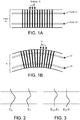
- FIGS 1A and 1B show (two-dimensionally) a fiber 8 with two single-mode cores 12, 14 displaced from the central axis and a Bragg grating 16 in an unbent and bent shape, respectively.
- the grating forms a set of vertical planes in the core in Figure 1A and tilted planes in Figure 1B .
- the two cores reflect the same wavelength.
- the top core is stretched and the bottom core is compressed, which changes the periodicity of the Bragg grating 16 seen by each core.
- a different wavelength is reflected at the grating in each of the two single-mode cores.
- the two modes will have electric field envelopes that look like those in Figure 2 which illustrates a first lower order mode field E 0 and a second higher order mode field E 1 in a two dimensional fiber waveguide. If both modes are launched, they propagate down the fiber with a linearly varying phase between them. When the two modes are in phase, their fields will sum and the total [ E 0 + E 1 ] will be weighted toward the top of the waveguide, and when they are out of phase, their fields will subtract and the combination [ E 0 - E 1 ] will be weighted toward the bottom of the waveguide as illustrated by the "peaks" shown in Figure 3 .
- FIGs 4A and 4B show straight and bent conditions of a two dimensional fiber waveguide and how it affects the spacing in a Bragg grating in the waveguide. Bending the waveguide causes the top and bottom of the waveguide to expand or compress. If there is a grating physically in the core, then reflections from this core grating can be detected in both the top and the bottom of the waveguide.
- the sum of the fields will measure the grating in the top of the core, and the difference of the fields will measure the grating in the bottom of the core.
- Cross coupling coefficients, ⁇ represent the scattering of light from the forward propagating modes to the backward propagating modes in the core grating.
- Figure 5 illustrates an electric field incident on and interacting with the grating resulting in some of the incident field E + being transmitted (a forward propagating mode) and some of the incident field E - being reflected (a backward propagating mode). Another way of describing this interaction is "cross coupling" (or simply “coupling”) the forward propagating mode and the backward propagating mode in the grating.
- four types of backward coupling can occur including: coupling from the forward propagating first order mode to the backward propagating first order mode (and having a coupling coefficient ⁇ 00 ), coupling from the forward propagating first order mode to the backward propagating second order mode (and having a coupling coefficient ⁇ 01 ), coupling from the forward propagating second order mode to the backward propagating second order mode (and having a coupling coefficient ⁇ 11 ), and coupling from the forward propagating second order mode to the backward propagating first order mode (and having a coupling coefficient ⁇ 10 ).
- Figures 6A-6D show all of the forward to backward coupling modes in this example.
- Modeling waveguide systems as ideal lossless waveguide systems, coupling coefficients ⁇ 01 ⁇ 10 ⁇ , and so there are three independent coupling coefficients available to measure: ⁇ 00 , ⁇ 01 , and ⁇ 11 .
- the local pattern of the Bragg grating determines the magnitude of the cross coupling or the coupling coefficients.
- distributed measurements of these three coupling coefficients can be used to calculate the local frequency of the grating (which determined by the tilt of the grating, which in turn determined by the amount of bending of the grating) at every point along the fiber wave guide.
- the manner in which these coupling coefficients are measured, and the corrections used to calculate the local frequency of a Bragg grating in the fiber core are described in detail below for a non-limiting and example case of a three dimensional waveguide.
- Previous fiber-optic shape sensing systems use a multi-core fiber or multiple single core fibers, where each core is a single mode fiber and typically has gratings written along the length of the core. Bend, twist, and/or strain cause local stretching or compressing of the grating pattern. These grating changes relate directly to the applied bend, twist, or strain and can be quantified by measuring the phase change vs. distance along the fiber with respect to a reference state. A matrix can be calculated via knowledge of the fiber geometry and/or calibration, and used to convert phase change in four cores to bend, twist, and strain.
- the variations in the core grating pattern are measured and processed with distance along the fiber and with cross-sectional location in the fiber core. For example, if the fiber is bent in one direction, the grating pattern is compressed on the side of the core on the inside of the bend, stretched on the side of the core on the outside of the bend, and unchanged along the neutral axis.
- Figure 7A shows a grating in an unbent multi-core single mode fiber
- Figure 7B shows the same multi-core when bent
- Figure 7C shows a single core multiple mode fiber with the same grating pattern bent in the same way. The periodicity of the grating pattern varies across the cross-sectional area of the core.
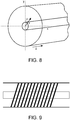
- Figure 8 is a reference diagram of a single core fiber with x, y, z axes, a vector/radius r, and an angle ⁇ . These labels are used in the some of the following figures and in the description below.
- Twist may be measured using a helixed fiber that uses multiple single mode cores disposed in a helical manner as described in the patents referenced in the introduction. But with a single core, multiple mode sensing fiber, a helixed fiber is no longer available for measuring twist.
- a grating pattern can be used to detect twist in the fiber. Construction of an example grating pattern is now described.
- Figure 9 shows an example of a tilted Bragg grating written in a single core.
- Figure 10 shows an example intensity plot of the index modulation of an example tilted Bragg grating.
- An index modulation is another way to represent the grating pattern. Note the x axis for the core is plotted horizontally, and z axis for the core is plotted vertically.
- This type of grating can be written in a fiber core using a phase mask that is tilted with respect to the fiber.
- Figure 11 shows an example phase mask to write a Bragg grating in a typical orientation with respect to the fiber when writing gratings.
- Figure 12 shows how the mask can be tilted to write a tilted grating.
- the mask can be made with the pattern tilted in order to write the desired tilted grating.
- FIG. 14 shows an example intensity plot of a grating pattern created when the two tilted gratings are written overtop of one another in the core.
- the dim/blurry areas along the vertical z axis at about 20, 60, 140, and 180 units of distance on the hroizontal x axis represent areas where destructive interference has "washed out" the grating amplitude.
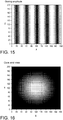
- Figure 15 shows an example amplitude envelope of the overlapped tilted gratings. Lighter areas represent stronger grating amplitude, and darker areas represent weaker grating amplitude where the grating amplitude is washed out. This plot represents the grating amplitude along the length of the fiber (axis z) vs. one cross sectional axis of the fiber, x.
- Figure 16 is an example intensity plot of a germanium doping concentration in an example fiber core looking at a cross section of the core in the x-y plane. This example fiber is only photosensitive in the core, and the grating only exists in the core.
- Figure 17 shows the grating amplitude features created by writing tilted gratings on top of one another within core 13 of the optical fiber 10.
- Figure 18 is an example intensity plot of an end view of the fiber in the x-y plane created by writing tilted gratings on top of one another.
- a grating pattern (like the pattern described above and an amplitude like that shown in Figure 15 ) written in a single core varies with bend, strain, and twist.
- various embodiments determine the cross-sectional variation in the grating pattern-which can also be described as the cross-sectional index perturbation-as a function of distance along the fiber. If the cross-sectional variation in the grating pattern can be determined, then the bend, strain, and twist as function of distance along the fiber can be determined.
- the index perturbation in a fiber core determines the cross-coupling between forward traveling and backward traveling modes.
- the index perturbation is the core grating.
- the core is probed with light having forward traveling modes, and the backward traveling modes created by the grating are detected. Because the input (forward traveling) modes may be determined in advance, and because the output (backward traveling) modes can be measured and the coupling coefficients determined, mode coupling is used the example embodiments to determine the index perturbation (the state of the grating such as pulled, compressed, bent, and/or twisted) that was present.
- the single core guides three modes for a detailed example. However, a single core that guides more than three modes may also be used.
- a representation of the index perturbation (the core grating) across the cross section of the example fiber at any given location may be determined by measuring the coupling coefficients between the back scattered modes. Assume that the single core fiber supports three modes E 0 (circular), E H (horizontal), and E V (vertical), two of them degenerate.
- the variable w is the Gaussian width of the mode and ⁇ is the propagation constant of the mode.
- Figure 19 shows scalar field plots of three lowest order LP modes E 0 (circular), E H (horizontal), and E V (vertical).
- ⁇ mn ⁇ E m x y ⁇ x y E n ⁇ x y e i ⁇ m + ⁇ n ⁇ k z dx dy
- ⁇ ( x,y ) e -ikz is the periodic index perturbation (the grating in the core) within the optical fiber
- ⁇ m and ⁇ n are the propagation constants of the two non-degenerate modes
- x and y are the cross sectional axes
- z is the dimension along the axis of the fiber.
- ⁇ mn ⁇ 0 a ⁇ 0 2 ⁇ E m r ⁇ ⁇ r ⁇ E n ⁇ r ⁇ e i ⁇ m + ⁇ n ⁇ k z rdrd ⁇ .
- Figure 20 illustrates the six decomposition functions of the six cross coupling possibilities for this example.
- Figure 21 shows decomposition functions for decomposing index perturbation for this example.
- the grating modulation e.g., changes in the grating caused by strain, stress, and/or twist
- ⁇ ( r, ⁇ ) e -ikz may be reconstructed using these coefficients, ⁇ mn , as the weight factor on summation of the decomposition function ⁇ mn ( r , ⁇ ).
- ⁇ p ⁇ ⁇ ⁇ ⁇ mn ⁇ mn r ⁇ ⁇ ⁇ mn E m r ⁇ E n ⁇ r ⁇ .
- This decomposition method of determining the distribution of a Bragg grating across the cross section of a single multimode core was simulated for two tilted and overlapped Bragg gratings, such as described above.
- the plots in Figure 21 represent the grating amplitude across the core cross-section and show simulated, compound, tilted grating index profiles on the left and the grating profiles successfully reconstructed from the overlap function decomposition on the right.
- the top two images are without fiber twist, the bottom two with twist.
- the simulation results show that the overlap integrals provide significant reconstruction capability and the lower right reconstruction shows that twist of the grating structure can be determined.
- ⁇ r ⁇ ⁇ ⁇ move r ⁇ ⁇ ⁇ base ⁇ r ⁇
- ⁇ x y ⁇ ⁇ move x y ⁇ ⁇ base ⁇ x y
- b x a horizontal bend
- b y a linear phase change as a function of y
- stretch ⁇
- twist ⁇
- Estimates can be determined for each of these shape parameters b x , b y , ⁇ , and ⁇ . These estimates can essentially function as a shape conversion matrix to convert from phase measurements to pitch, yaw, twist and strain.
- ⁇ ⁇ ⁇ ⁇ move x y ⁇ ⁇ base ⁇ x y dA
- b x max ⁇ ⁇ move x y ⁇ ⁇ base ⁇ x y e ib x dA
- the shape of the fiber may be determined using three dimensional rotations and projections described in U.S. patents 7,781,724 and 8,773,650 identified in the introduction.
- some embodiments In addition to using the measured coupling coefficients ( ⁇ mn ) to determine the index perturbation in a single multimode core, some embodiments also measure the coupling coefficients. Some embodiments get the energy from single mode fibers into and out of each of the different modes in a way that is power efficient (the detecting fibers are typically coupled to photodiode detectors in an Optical Frequency Domain Reflectometry (OFDR) system).
- OFDR Optical Frequency Domain Reflectometry
- a fused tapered coupler, tapering multiple single mode fibers and fusing them to different locations on the multimode core may be an option if the tapering can be done as the mode coupling was monitored in a 3x3 coupler. Another option abuts a bundle of single mode cores up against the larger multimode core.
- Some embodiments use this option when the cores are surrounded by little or no cladding. Another option is to image the multimode core directly onto a bundle of single mode fibers with a large magnification. Some embodiments use this option when the system can function with the inefficiencies resulting from light that may be captured by the cladding surrounding each of the single mode fibers.
- Some embodiments including this last option of directly imaging the multimode core reduce the inefficiencies by using a micro lens array with a sufficiently large fill-factor and a numerical aperture (NA) that matches the optical fiber with the multimode core more closely (e.g., between 0.1 and 0.25 in some cases).
- NA numerical aperture
- An example of a bulk-optic design for getting energy from each of the different modes into a corresponding single-mode detecting fiber in a way that is power efficient is shown in Figure 22 .
- the design may use a commercially-available microlens array 22 and includes a fiber array 20 of three single core, single mode detecting fibers for directing light from each of the three modes of light provided from a single multimode core 13 in a single core multimode sensing fiber 10 into three single core, single mode detecting fibers in the fiber array 20.
- Multimode light from multimode core 13 is imaged by lens 24 to the microlens array 22.
- Figure 22 shows specific values for dimensions and other parameters that are useful for specific embodiments, and are only examples and are not limiting.
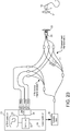
- Figure 23 shows an example system for interrogating a single core multimode sensing fiber 10 with multiple modes.
- the interrogation system is controlled by an OFDR controller 30 that includes one or more computers 32 coupled to (i) a laser controller 34 that controls a tunable laser 36 through a range of frequencies or wavelengths, (ii) a display, and (iii) acquisition circuitry including photodiodes, analog to digital conversion circuitry, sampling circuitry.
- the laser controller 34 controls the tunable laser 36 to probe the single core multimode sensing fiber 10 with three separate single core fibers in the three measurement branches, each with a unique delay corresponding to a different length of fiber L, L1, and L2.
- the laser light from each of the three input fibers is coupled via the fiber array 20 through the microlens array 22 and lens 24 into the single core 13, and the reflected light from each of the three modes from the single core grating is delivered by the microlens array 22 to its corresponding single core single mode detecting fiber in the fiber array 20 for detection and processing in the OFDR controller 30.
- the delays of the three input fibers are larger than the total delay associated with the single core multimode sensing fiber 10, then all of the cross coupled terms between input and output fibers of the measurement interferometer will appear at different delays and on unique detectors. If the fiber lengths for each output fiber are the same, then the overall delay is determined by the input fiber in this example.
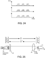
- Figure 24 are graphs that illustrate 9 coupling terms m11-m33.
- the three graphs of amplitude vs. delay represent the amplitude of light detected on each of the three detectors at the acquisition circuitry 38 corresponding to the three single mode fibers in the fiber array 20.
- the first subscript on the coupling terms, m identifies the input fiber and the second subscript identifies the output fiber (the detector the signal is detected on). So m31 represents the amount of light sent in on fiber 3 and detected on detector fiber 1.
- the index perturbation is determined by measuring the cross coupling coefficients detected at the multiple (three in the example) single mode fibers in the fiber array 20 that correspond to but are not identical to the modes of the single core 13 in the single core multimode sensing fiber 10.
- Figure 24 described above illustrates the coupling coefficients between the three measured components coupled to the single mode fibers in the fiber array 20.
- These cross-coupling coefficients for these single mode fibers can be measured directly by the OFDR controller 30, but they need to be connected or converted to the actual modal cross-coupling coefficients for the three modes of the single core 13 in the single core multimode sensing fiber 10.
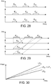
- FIG. 25 shows an example model of an optical connection system as two matrices connected by the alpha matrix ⁇ ⁇ ⁇ .
- E 0 is the circularly symmetric LP01 mode
- E V is the vertically oriented LP11 mode
- E H is the horizontally oriented LP11 mode.
- a ⁇ out ⁇ ⁇ ⁇ K ⁇ ⁇ ⁇ ⁇ ⁇ ⁇ 1
- a ⁇ in ⁇ 11 ⁇ 21 ⁇ 31 ⁇ 21 ⁇ 22 ⁇ 32 ⁇ 31 ⁇ 32 ⁇ 33 ⁇ 11 ⁇ 21 ⁇ 31 ⁇ 21 ⁇ 22 ⁇ 32 ⁇ 31 ⁇ 32 ⁇ 33 ⁇ 11 ⁇ 21 ⁇ 31 ⁇ 21 ⁇ 22 ⁇ 32 ⁇ 31 ⁇ 32 ⁇ 33 ⁇ 11 ⁇ 21 ⁇ 31 ⁇ 21 ⁇ 22 ⁇ 32 ⁇ 31 ⁇ 32 ⁇ 33 ⁇ 11 ⁇ 21 ⁇ 31 ⁇ 21 ⁇ 22 ⁇ 32 ⁇ 31 ⁇ 32 ⁇ 33 ⁇ 1 A 1 A 2 A 3
- a ⁇ out ⁇ ⁇ ⁇ K ⁇ ⁇ ⁇ ⁇ ⁇ 1
- a ⁇ in m 11 m 21 m 31 m 21 m 22 m 32 m 31 m 32 m 33
- a 3 M ⁇ ⁇ A ⁇ in
- ⁇ K ⁇ -1 is what is measured with the time-delayed interrogation network shown in Figure 23 .
- the objective is to determine the modal cross-coupling coefficients represented by the cross-coupling coefficients matrix K corresponding to the state of the core grating, what can be actually measured by the OFDR interrogation system is the M matrix.
- Embodiments determine the elements that form the matrix M in the following manner.
- An OFDR scan of a single core multimode fiber with a cleaved end is used to separate out the E 0 (LP01) mode based upon propagation time to the end of the cleave and also to separate the cross coupling terms.
- Figure 26 is a graph of an example impulse response or propagation delay of a single core multimode fiber with a cleaved end. The reflection from the cleaved end is shown and labeled as "fiber endface.” The different propagation modes propagate along the fiber at different speeds, which means they can be separated and identified.
- the E 0 (LP01) mode has a longer propagation time, its reflection will arrive later at the OFDR detector than the E V and E H (LP 11) mode reflections.
- the light that travels down the fiber in the E 0 (LP01) mode and couples to the E V and E H (LP11) modes at the cleave will arrive with a delay exactly in between the two modes.
- Figure 27 is a graph of the example impulse response delays in Figure 26 relabeled to identify the modal assignments (coupling coefficients). From Figure 27 , the three groups of coupling coefficients can be separated and filtered around each of the different delays (the distinct and separate impulse response amplitude lines). The terms are isolated by first windowing the complex data around the reflection peak, and then performing a Fourier transform to compute the frequency domain complex spectrum of the peak. First, the reflected coupling coefficient ⁇ 22 for mode E 0 (LP01) is isolated using the windowing and transformation to mathematically separate the peak on all channels and at all offset delays to give a matrix of filtered values.
- the OFDR controller applies a time domain window filter (like a bandpass filter) around the E 0 (LP01) delay peak.
- M 1 ⁇ ⁇ ⁇ 11 ⁇ 21 ⁇ 31 ⁇ 21 ⁇ 22 ⁇ 32 ⁇ 31 ⁇ 32 ⁇ 33 ⁇ 11 0 ⁇ 31 0 0 0 ⁇ 13 0 ⁇ 33 ⁇ 11 ⁇ 21 ⁇ 31 ⁇ 21 ⁇ 22 ⁇ 32 ⁇ 31 ⁇ 32 ⁇ 33 ⁇ 1
- the connector matrix: ⁇ 11 ⁇ 21 ⁇ 31 ⁇ 21 ⁇ 22 ⁇ 32 ⁇ 31 ⁇ 32 ⁇ 33 can be constructed from the eigenvectors of M 0 + M 1 using linear algebra.
- the connector ⁇ matrix which defines coupling between the single mode fibers and the single core multimode sensing fiber, it remains constant for a given fiber connection.
- This connector ⁇ matrix and its inverse define how light couples from the OFDR interrogation system to the modes of the single core multimode sensing fiber and back. Knowing the values for this connector ⁇ matrix and the input light, the output light is measured by the OFDR interrogation system, and from these three things, the OFDR interrogation system calculates the values of the current modal cross coupling coefficients, or the K matrix.
- the phase perturbations in the single core multimode sensing fiber 10 that produced the measured coupling ( ⁇ ) coefficients and which represent the state of the grating in the single core multimode sensing fiber 10 are calculated. From these determined phase perturbations corresponding to the state of the core grating, the bend and twist of the single core multimode sensing fiber 10 can be calculated at every point along the single core multimode fiber 10. These bend and twist values can then be used to calculate the shape of the multimode sensing fiber 10.
- the approach described above provides measurements of the coupling between modes along the length of the single core multimode sensing fiber 10 as a function of time delay.
- further corrections are made to address differing group velocities between modes. For example, to address the differing group velocities causing the mode coupling coefficients ( ⁇ ) to be spread over different delay ranges depending on which modes the light propagated in and for how long.
- Figure 28 graphs example fiber mode responses with exaggerated time-length differences to illustrate how the effective length of the fiber appears to be different for each of the modes due to differences in group delay between the modes.
- the time delay amounts are the same, while in Figure 28 , the time delay amounts are different due to group delay effects. These group delay effects can be accounted for by resampling the data when the coupling coefficients are identified.
- the coupling coefficients identification includes mapping the physical location in the fiber where the coupling took place to the same index for each mode.
- index is the location along the length of the fiber before it has been scaled to engineering lengths. The data is lined up to represent the same location at the same index. This mapping is performed for each of the 6 independent coupling coefficients in this example (although there are 9 coupling coefficients, several have the same effective group index such as ⁇ 13 and ⁇ 31 ).
- Figure 29 is a graph showing an example of resampling and alignment of coupling coefficients ⁇ 11 , ⁇ 21 , and ⁇ 31 showing conversion of them from the time domain to the spatial domain (the horizontal axis in Figure 29 aligns with the z axis of the single core multimode sensing fiber 10. This conversion is accomplished by multiplying the time label of each of the coupling coefficients ⁇ 11 , ⁇ 21 , and ⁇ 31 in the time domain by the speed of light for that coupling coefficient.
- each mode In addition to propagating with different group delays, each mode also propagates with a different wavenumber, or effective refractive index, meaning that each mode accumulates phase at a different rate as it propagates down the single core multimode sensing fiber 10.
- Figure 30 graphs example phase accumulations for different coupling coefficients as a function of delay.
- the LP11 and LP01 self-coupling terms are both weighted integrals over the single core multimode sensing fiber 10 in this example. As a result, even for random Rayleigh scatter, the LP11 and LP01 self-coupling terms are substantially similar. If the sensing fiber is straight, this common term in the coupling terms allows precise measurements of the difference between the phase propagation terms for the LP11 and LP01 modes along the fiber length. Further, this difference in effective refractive index can be used to predict the phase change in the cross term phases, such as by assuming the cross term phase accumulations are exactly halfway between the pure LP11 and LP01 phase delays. These calculated phase changes due to the different effective refractive indexes of the modes are then applied to the measured and resampled coupling coefficients before the scattering cross section is calculated.
- FIG 31 is a flowchart showing example procedures for using a single core, multiple mode fiber for sensing shape in accordance with example embodiments.
- step S1 light is input into three (or more) modes supported by the single multimode core fiber.
- the grating of the core causes forward traveling modes to be reflected into backward traveling modes as shown in step S2.
- step S3 reflected light is detected, converted into electrical signals, converted from analog format into digital format, processed in the OFDR controller to calculate the cross coupling coefficients.
- decomposition functions are used to determine the index perturbation, or the current state of the grating, when compared to a measurement in a known state (such as the fiber positioned in a straight line).
- step S5 the pitch, yaw, twist, and strain from the change in the index perturbation is determined.
- step S6 the fiber shape is determined from the pitch, yaw, twist, and strain determined in step S5.
- Figure 32 is a flowchart showing example procedures for using a single core, multiple mode fiber for sensing shape in accordance with example embodiments.
- step S10 light from the tunable laser is split between measurement and reference paths using for example the OFDR system in Figure 23 .
- the measurement light is split into three input fibers, each input fiber having a different delay.
- step S12 light from the three input fibers is coupled into the single core multimode sensing fiber using a lens array.
- forward propagating life from the three modes is coupled into backward traveling light in the three modes via the core grating.
- the light in the backward traveling modes is coupled into the three single mode fibers (now output fibers) via the lens array.
- step S15 this backward traveling light is combined with the reference light and detected on three detectors.
- step S16 data from the three detectors is processed to determine the M matrix which couples the coupling coefficients between the input light and the output light.
- step S17 using the alpha matrix, which is the matrix describing the coupling between the single mode input fibers and the modes of the single core multimode fiber, cross coupling coefficients between the modes of the single core multimode fiber are determined. These cross coupling coefficients form the K matrix.
- step S18 these cross coupling coefficients are then used to calculate the current index perturbation, which is the core grating, and from there, the shape of the single core multimode sensing fiber is calculated as in steps S4-S6 in Figure 31 .
- Figure 33 is a flowchart showing example procedures for calibrating and then using a single core, multiple mode fiber for sensing shape in accordance with example embodiments. Two different process stages are included and coupled loosely with a dashed line. The first process stage is performed before the fiber is used for shape measurements. The second process stage is used when the sensing fiber is to perform shape measurement.
- step S20 the single core multimode fiber is connected to a multimode interrogation system such as the OFDR system shown in Figure 23 .
- step S21 the shape sensing fiber is positioned in a straight line or in another known orientation.
- the cleaved end response of the fiber is measured in step S22.
- the decoupling matrix is calculated to convert the measurement modes to fiber modes in step S23.
- the decoupling matrix is referred to above as the alpha matrix and is determined following steps S20-S23.
- the next steps S24 through S26 relate to determining reference or baseline measurements of the shape sensing fiber in a known state.
- step S24 the cleaved end is terminated, and the coupling coefficients are measured for the shape sensing fiber.
- step S25 the coupling coefficients are resampled into the same physical frame.
- step S26 corrections are determined for the wavenumber differences.
- step S30 describes changing the shape of the fiber to a measurement orientation.
- the fiber response is measured using the interrogation system.
- the decoupling or alpha matrix is applied to the measured response in step S32.
- the coupling coefficients are resampled in step S33, and the wavenumber corrections are applied in step S34.
- the index modulation profile change is calculated at each point along the sensing fiber in step S35.
- step S36 the bend, twist, and strain are calculated each point along the fiber, and from these values, the shape of the sensing fiber is calculated in step S37.
- the inventors Having determined how to make and use a single core multimode fiber to determine shape using an OFDR interrogation method and overlapped tilted gratings, the inventors tested different fiber core sizes and estimated their sensitivity to detecting twist.
- V-number a normalized frequency parameter known as the V-number.
- a V-number of around 3.5 was selected in order to guide the LP11 modes tightly, while excluding the LP21 and LP02 modes.
- Figure 36 is a graph showing modal propagation values for Linear Polarization Modes vs. V-number.
- the V-number is given by the equation below.
- n 1 is the index of refraction of the core
- n 2 is the index of the cladding
- ⁇ is the wavelength of the light
- r is the core radius
- NA is the Numerical Aperture.
- the rotational period of the skew rays can be calculated from the difference in the wavenumbers between the modes present in the fiber. This difference may be characterized by the parameter b , which can be used to calculate the wavenumbers for each mode.
- This twist sensitivity may be doubled to a value that is about half of the sensitivity in a multi-core shape sensing fiber. This demonstrates that a simple step-index, three-mode single core fiber has sufficient twist sensitivity to function as an effective shape sensor.
- a single small core as shown in Figure 35 supports just a few (e.g., 3) modes
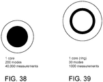
- a single large core as shown in Figure 38 supports many (e.g., 200) modes in addition to the axial ray (shown in Figure 34B ) and skew rays (shown in Figure 34A ) described above.
- all of these modes can couple together when the fiber is perturbed, leading to a multitude of interactions that are measured in order to get accurate results. This large number of measurements may or may not be worthwhile depending on the application.
- Figure 39 shows an example single core multimode fiber where the core is annular and supports 30 modes. Additional sensitivity afforded by the larger core shown in Figure 38 may be achieved using an annular core and eliminate the interior modes. Recognizing that axial rays can actually propagate parallel to the axis, but not on the axis, the annular core limits the number of modes present and the complexity of the measurement.
- the technology described provides a single core multimode fiber that can be used to accurately sense shape and can be manufactured quite simply and cost effectively as compared to multicore shape sensing fiber.
- One non-limiting example application is to a fiber optic shape sensing system for a robotic surgical arm in which one or more of the various technical features and/or embodiments described above may be used.
- control system including at least one memory and at least one processor, and often a plurality of processors.
- the control system also includes programmed instructions (e.g., a computer-readable medium storing the instructions) to implement some or all of the methods described in accordance with aspects disclosed herein.
- the control system may include two or more data processing circuits with one portion of the processing optionally being performed on or adjacent the tool, and another portion of the processing being performed at a station (e.g. an operator input system or central processing system or the like) remote from the tool. Any of a wide variety of centralized or distributed data processing architectures may be employed.
- control system supports wireless communication protocols such as Bluetooth, IrDA, HomeRF, IEEE 802.11, DECT, and Wireless Telemetry.
Claims (15)
- Système d'interrogation optique pour une fibre de détection (10), le système comprenant :un appareil interférométrique pour sonder un cœur multimode unique (13) de la fibre de détection (10) sur une plage de longueurs d'onde prédéterminées de lumière, le cœur multimode unique (13) ayant au moins trois modes de propagation de la lumière, l'appareil interférométrique comprenant au moins trois interféromètres (3) incluant au moins trois branches de référence et au moins trois branches de mesure, les au moins trois branches de mesure ayant des retards optiques différents et comprenant un réseau de fibres de détection à cœur unique à mode unique associées (20), chaque fibre de détection à cœur unique à mode unique pour coupler la lumière dans un mode de propagation de la lumière des au moins trois modes de propagation de la lumière, l'appareil interférométrique comprenant en outre un circuit d'acquisition (38) pour détecter des données interférométriques de mesure associées à une lumière réfléchie couplée à partir des au moins trois modes de propagation de la lumière du cœur multimode unique (13) de retour dans le réseau de fibres à cœur unique à mode unique (20) pour chaque longueur d'onde prédéterminée dans la plage ; etun circuit de traitement de données (32) pour :traiter les données interférométriques de mesure pour déterminer des coefficients de couplage croisé modal associés aux au moins trois modes de propagation de la lumière du cœur multimode unique (13) ;déterminer une perturbation d'indice transversale du cœur multimode unique (13) à partir des coefficients de couplage croisé modal ; etdéterminer les paramètres de contrainte, de flexion et de torsion de la fibre de détection (10) à partir de la perturbation d'indice transversale par rapport à une perturbation d'indice transversale de ligne de base.
- Système d'interrogation optique selon la revendication 1, dans lequel le circuit de traitement de données est configuré pour déterminer une forme de la fibre de détection (10) sur la base des paramètres de contrainte, de flexion, et de torsion.
- Système d'interrogation optique selon la revendication 1 ou 2, étant en outre conçu pour sonder ledit cœur multimode unique (13), dans lequel ledit cœur multimode unique (13) inclut en outre un motif de grille qui varie en fonction de la flexion, de la contrainte, et de la torsion appliquées à la fibre de détection (10), et dans lequel une variation du motif de grille correspond à un changement de la perturbation d'indice transversale déterminée par rapport à la perturbation d'indice transversale de ligne de base.
- Système d'interrogation optique selon la revendication 3, dans lequel le motif de grille est créé par le chevauchement de grilles inclinées dans le cœur multimode unique (13).
- Système d'interrogation optique selon l'une quelconque des revendications 1 à 4, dans lequel le circuit de traitement de données (32) est configuré pour :traiter les données interférométriques de mesure pour déterminer des termes de couplage entre l'entrée de lumière dans le cœur multimode unique (13) à partir des fibres à cœur unique à mode unique (20) et la sortie de lumière à partir du cœur multimode à cœur unique (13) dans les fibres à cœur unique à mode unique (20), etdéterminer les coefficients de couplage croisé modal à partir des termes de couplage déterminés en conjonction avec une matrice de connexion décrivant le couplage entre les fibres à cœur unique à mode unique (20) et le cœur multimode unique (13).
- Système d'interrogation optique selon l'une quelconque des revendications 1 à 5, dans lequel le circuit de traitement de données (32) est configuré pour déterminer la perturbation d'indice transversale à partir des coefficients de couplage croisé modal en utilisant des fonctions de décomposition.
- Système d'interrogation optique selon l'une quelconque des revendications 1 à 6, étant conçu en outre pour sonder ledit cœur multimode unique (13), dans lequel ledit cœur multimode unique (13) comprend en outre une forme qui limite un nombre des au moins trois modes de propagation de la lumière au-dessous d'un nombre prédéterminé tout en fournissant une sensibilité prédéterminée au paramètre de torsion.
- Système d'interrogation optique selon la revendication 7, dans lequel le cœur multimode unique (13) est en forme d'anneau en section transversale.
- Système d'interrogation optique selon l'une quelconque des revendications 1 à 8, dans lequel l'appareil interférométrique inclut en outre :
un laser accordable (36) pour générer la lumière sur la plage de longueurs d'onde prédéterminées. - Procédé dans un système d'interrogation optique ayant une fibre de détection (10) ayant un cœur multimode unique (13), le cœur multimode unique (13) ayant au moins trois modes de propagation de la lumière, le système d'interrogation optique comprenant un appareil interférométrique et un circuit de traitement de données (32), l'appareil interférométrique conçu pour sonder le cœur multimode unique (13) sur une plage de longueurs d'onde prédéterminées de lumière, l'appareil interférométrique comprenant au moins trois interféromètres (3) incluant au moins trois branches de référence et au moins trois branches de mesure, les au moins trois branches de mesure ayant des retards optiques différents et comprenant un réseau de fibres de détection à cœur unique à mode unique associées (20), chaque fibre de détection à cœur unique à mode unique conçue pour coupler la lumière dans un mode de propagation de la lumière des au moins trois modes de propagation de la lumière, l'appareil interférométrique comprenant en outre un circuit d'acquisition (38) pour détecter des données interférométriques de mesure associées à une lumière réfléchie couplée à partir des au moins trois modes de propagation de la lumière du cœur multimode unique (13) de retour dans le réseau de fibres à cœur unique à mode unique (20) pour chaque longueur d'onde prédéterminée dans la plage, le procédé comprenant :le sondage, avec l'appareil interférométrique, du cœur multimode unique (13) sur la plage de longueurs d'onde prédéterminées et la détection des données interférométriques de mesure associées aux au moins trois modes de propagation de la lumière du cœur multimode unique (13) pour chaque longueur d'onde prédéterminée dans la plage ; etle traitement, avec le circuit de traitement de données (32), des données interférométriques de mesure pour déterminer des coefficients de couplage croisé modal associés aux au moins trois modes de propagation du cœur multimode unique (13) ;la détermination, avec le circuit de traitement de données (32), d'une perturbation d'indice transversale du cœur multimode unique (13) à partir des coefficients de couplage croisé modal ; etla détermination, avec le circuit de traitement de données (32), de paramètres de contrainte, de flexion, et de torsion de la fibre de détection (10) à partir de la perturbation d'indice transversale déterminée par rapport à une perturbation d'indice transversale de ligne de base.
- Procédé selon la revendication 10, comprenant en outre une forme de la fibre de détection (10) basée sur les paramètres de contrainte, de flexion, et de torsion.
- Procédé selon la revendication 10 ou 11, comprenant en outre :
dans lequel la perturbation d'indice transversale correspond à un motif de grille du cœur multimode unique (13) qui varie avec la contrainte, la flexion, et la torsion appliquées à la fibre de détection (10). - Procédé selon l'une quelconque des revendications 10 à 12, dans lequel la perturbation d'indice transversale est déterminée en utilisant des fonctions de décomposition.
- Procédé selon l'une quelconque des revendications 10 à 13, dans lequel le cœur multimode unique (13) est formé pour limiter un nombre des au moins trois modes de propagation de la lumière au-dessous d'un nombre prédéterminé tout en fournissant une sensibilité prédéterminée au paramètre de torsion.
- Support lisible par machine non transitoire comprenant une pluralité d'instructions lisibles par machine pour amener le circuit de traitement de données du système d'interrogation optique selon la revendication 1 à réaliser des opérations comprenant :le traitement de données interférométriques de mesure associées à au moins trois modes de propagation de la lumière acquises à partir d'un cœur multimode unique (13) d'une fibre de détection (10) sur une plage de longueurs d'onde prédéterminées pour déterminer des coefficients de couplage croisé modal associés aux au moins trois modes de propagation de la lumière du cœur multimode unique (13) ;la détermination d'une perturbation d'indice transversale du cœur multimode unique (13) à partir des coefficients de couplage croisé modal ; etla détermination de paramètres de contrainte, de courbure, et de flexion de la fibre de détection (10) à partir de la perturbation d'indice transversale par rapport à une perturbation d'indice transversale de ligne de base.
Priority Applications (2)
| Application Number | Priority Date | Filing Date | Title |
|---|---|---|---|
| EP23191086.0A EP4249971A3 (fr) | 2016-12-29 | 2017-12-20 | Procédés et appareil pour déterminer un ou plusieurs paramètres de forme à l'aide d'une fibre de détection ayant un c ur unique à multiples modes de propagation de lumière |
| EP21200293.5A EP3957960B1 (fr) | 2016-12-29 | 2017-12-20 | Procédés et appareil pour déterminer un ou plusieurs paramètres de forme à l'aide d'une fibre de détection ayant un c ur unique à multiples modes de propagation de lumière |
Applications Claiming Priority (2)
| Application Number | Priority Date | Filing Date | Title |
|---|---|---|---|
| US201662440035P | 2016-12-29 | 2016-12-29 | |
| PCT/US2017/067588 WO2018125713A1 (fr) | 2016-12-29 | 2017-12-20 | Procédés et appareil pour déterminer un ou plusieurs paramètres de forme à l'aide d'une fibre de détection ayant un cœur unique à multiples modes de propagation de lumière |
Related Child Applications (2)
| Application Number | Title | Priority Date | Filing Date |
|---|---|---|---|
| EP23191086.0A Division EP4249971A3 (fr) | 2016-12-29 | 2017-12-20 | Procédés et appareil pour déterminer un ou plusieurs paramètres de forme à l'aide d'une fibre de détection ayant un c ur unique à multiples modes de propagation de lumière |
| EP21200293.5A Division EP3957960B1 (fr) | 2016-12-29 | 2017-12-20 | Procédés et appareil pour déterminer un ou plusieurs paramètres de forme à l'aide d'une fibre de détection ayant un c ur unique à multiples modes de propagation de lumière |
Publications (3)
| Publication Number | Publication Date |
|---|---|
| EP3563119A1 EP3563119A1 (fr) | 2019-11-06 |
| EP3563119A4 EP3563119A4 (fr) | 2019-12-25 |
| EP3563119B1 true EP3563119B1 (fr) | 2021-10-20 |
Family
ID=62710000
Family Applications (3)
| Application Number | Title | Priority Date | Filing Date |
|---|---|---|---|
| EP23191086.0A Pending EP4249971A3 (fr) | 2016-12-29 | 2017-12-20 | Procédés et appareil pour déterminer un ou plusieurs paramètres de forme à l'aide d'une fibre de détection ayant un c ur unique à multiples modes de propagation de lumière |
| EP17886412.0A Active EP3563119B1 (fr) | 2016-12-29 | 2017-12-20 | Procédés et appareil pour déterminer un ou plusieurs paramètres de forme à l'aide d'une fibre de détection ayant un coeur unique à multiples modes de propagation de lumière |
| EP21200293.5A Active EP3957960B1 (fr) | 2016-12-29 | 2017-12-20 | Procédés et appareil pour déterminer un ou plusieurs paramètres de forme à l'aide d'une fibre de détection ayant un c ur unique à multiples modes de propagation de lumière |
Family Applications Before (1)
| Application Number | Title | Priority Date | Filing Date |
|---|---|---|---|
| EP23191086.0A Pending EP4249971A3 (fr) | 2016-12-29 | 2017-12-20 | Procédés et appareil pour déterminer un ou plusieurs paramètres de forme à l'aide d'une fibre de détection ayant un c ur unique à multiples modes de propagation de lumière |
Family Applications After (1)
| Application Number | Title | Priority Date | Filing Date |
|---|---|---|---|
| EP21200293.5A Active EP3957960B1 (fr) | 2016-12-29 | 2017-12-20 | Procédés et appareil pour déterminer un ou plusieurs paramètres de forme à l'aide d'une fibre de détection ayant un c ur unique à multiples modes de propagation de lumière |
Country Status (4)
| Country | Link |
|---|---|
| US (3) | US11035699B2 (fr) |
| EP (3) | EP4249971A3 (fr) |
| CN (1) | CN110073174B (fr) |
| WO (1) | WO2018125713A1 (fr) |
Families Citing this family (8)
| Publication number | Priority date | Publication date | Assignee | Title |
|---|---|---|---|---|
| US11035699B2 (en) * | 2016-12-29 | 2021-06-15 | Intuitive Surgical Operations, Inc. | Methods and apparatus for determining shape parameter(s) using a sensing fiber having a single core with multiple light propagating modes |
| JP7401527B2 (ja) * | 2018-08-28 | 2023-12-19 | コーニンクレッカ フィリップス エヌ ヴェ | 光学形状感知及びスペクトル組織感知のための統合型ファイバ |
| CN110967048B (zh) * | 2019-12-28 | 2021-11-05 | 桂林电子科技大学 | 正交倾斜三芯光纤光栅并行集成Mach-Zehnder干涉仪 |
| CN111399121A (zh) * | 2020-04-30 | 2020-07-10 | 中国工程物理研究院激光聚变研究中心 | 一种光纤及激光切割机 |
| CN114448502A (zh) * | 2020-11-04 | 2022-05-06 | 中国移动通信有限公司研究院 | 简并模式内差分模式时延的测量方法及装置 |
| CN114448501B (zh) * | 2020-11-04 | 2024-04-19 | 中国移动通信有限公司研究院 | 简并模式内差分模式时延的测量方法及装置 |
| CN113188468B (zh) * | 2021-04-15 | 2022-07-05 | 广东工业大学 | 基于双芯少模光纤倾斜光栅的矢量弯曲传感系统及方法 |
| CN117073866A (zh) * | 2023-06-30 | 2023-11-17 | 南通大学 | 一种基于七芯光纤和蝴蝶结型的温度传感器及制备方法 |
Family Cites Families (40)
| Publication number | Priority date | Publication date | Assignee | Title |
|---|---|---|---|---|
| US4915468A (en) | 1987-02-20 | 1990-04-10 | The Board Of Trustees Of The Leland Stanford Junior University | Apparatus using two-mode optical waveguide with non-circular core |
| US5224182A (en) | 1991-08-29 | 1993-06-29 | Virginia Polytechnic Institute And State University | Spatially-weighted two-mode optical fiber sensors |
| KR960007884B1 (ko) * | 1993-04-24 | 1996-06-15 | 국방과학연구소 | 광섬유 격자를 이용한 광섬유소자 |
| US5848204A (en) * | 1995-09-08 | 1998-12-08 | California State University-Fullerton | Fiber devices and sensors based on multimode fiber Bragg gratings |
| US5798521A (en) * | 1996-02-27 | 1998-08-25 | The United States Of America As Represented By The Administrator Of The National Aeronautics And Space Administration | Apparatus and method for measuring strain in bragg gratings |
| WO1998001071A1 (fr) * | 1996-07-08 | 1998-01-15 | Animas Corporation | Capteur implantable et systeme de mesure et de controle in vivo de taux de constituants de fluides |
| US6069985A (en) * | 1998-08-10 | 2000-05-30 | Albin; Sacharia | Cross-fiber Bragg grating transducer |
| US6205263B1 (en) * | 1999-06-16 | 2001-03-20 | Intelligent Optical Systems | Distributed optical fiber sensor with controlled response |
| US6621960B2 (en) * | 2002-01-24 | 2003-09-16 | Oplink Communications, Inc. | Method of fabricating multiple superimposed fiber Bragg gratings |
| US20060013523A1 (en) * | 2004-07-16 | 2006-01-19 | Luna Innovations Incorporated | Fiber optic position and shape sensing device and method relating thereto |
| US7781724B2 (en) | 2004-07-16 | 2010-08-24 | Luna Innovations Incorporated | Fiber optic position and shape sensing device and method relating thereto |
| US7376307B2 (en) * | 2004-10-29 | 2008-05-20 | Matsushita Electric Industrial Co., Ltd | Multimode long period fiber bragg grating machined by ultrafast laser direct writing |
| US8989528B2 (en) | 2006-02-22 | 2015-03-24 | Hansen Medical, Inc. | Optical fiber grating sensors and methods of manufacture |
| WO2007149230A2 (fr) * | 2006-06-16 | 2007-12-27 | Luna Innovations Incorporated | Discrimination de l'effort et de la tempÉrature distribuÉs dans une fibre À maintien de la polarisation |
| WO2008111320A1 (fr) * | 2007-03-09 | 2008-09-18 | Mitsubishi Electric Corporation | Capteur à fibre optique |
| US8180185B2 (en) | 2007-03-22 | 2012-05-15 | General Electric Company | Fiber optic sensor for detecting multiple parameters in a harsh environment |
| US8622935B1 (en) * | 2007-05-25 | 2014-01-07 | Endosense Sa | Elongated surgical manipulator with body position and distal force sensing |
| US8351029B2 (en) * | 2007-12-06 | 2013-01-08 | Mitsubishi Electric Corporation | Optical fiber sensor |
| CN100582658C (zh) | 2008-02-29 | 2010-01-20 | 南开大学 | 基于光纤激光器的弯曲半径测量仪 |
| US8780339B2 (en) | 2009-07-15 | 2014-07-15 | Koninklijke Philips N.V. | Fiber shape sensing systems and methods |
| US8773650B2 (en) | 2009-09-18 | 2014-07-08 | Intuitive Surgical Operations, Inc. | Optical position and/or shape sensing |
| US9417057B2 (en) * | 2012-03-16 | 2016-08-16 | Koninklijke Philips N.V. | Optical sensing system for determining the position and/or shape of an associated object |
| US9772176B2 (en) * | 2013-06-13 | 2017-09-26 | Intuitive Surgical Operations, Inc. | Overlapped chirped fiber bragg grating sensing fiber and methods and apparatus for parameter measurement using same |
| US11266466B2 (en) | 2013-07-29 | 2022-03-08 | Intuitive Surgical Operations, Inc. | Shape sensor systems with redundant sensing |
| CN203932660U (zh) | 2014-05-23 | 2014-11-05 | 武汉锐科光纤激光器技术有限责任公司 | 一种高功率多芯光纤激光器 |
| WO2016122742A2 (fr) * | 2014-11-11 | 2016-08-04 | Luna Innovations Incorporated | Fibre optique et procédé et appareil pour la détection précise par fibre optique sous de multiples stimuli |
| CN107003473B (zh) * | 2014-12-15 | 2020-09-11 | 直观外科手术操作公司 | 用于应变和温度分离的多芯光纤中的不同的纤芯 |
| WO2016160513A1 (fr) * | 2015-03-27 | 2016-10-06 | Intuitive Surgical Operations, Inc. | Alignement interférométrique de fibres optique multicœurs à connecter |
| CN205642682U (zh) | 2016-04-15 | 2016-10-12 | 广西师范大学 | 基于保偏光纤萨格纳克环的光纤扭矩传感系统 |
| KR20240035639A (ko) * | 2016-05-11 | 2024-03-15 | 인튜어티브 서지컬 오퍼레이션즈 인코포레이티드 | 안전성을 위한 멀티코어 광섬유의 여분의 코어 |
| US10775157B2 (en) * | 2016-06-09 | 2020-09-15 | Intuitive Surgical Operations, Inc. | Methods and apparatus for calibration for a fiber optic shape sensor |
| EP3479056B1 (fr) * | 2016-06-29 | 2021-03-24 | Intuitive Surgical Operations Inc. | Procédés et appareil pour la surveillance et l'optimisation d'un interrogateur ofdr |
| CN114279363A (zh) * | 2016-07-08 | 2022-04-05 | 直观外科手术操作公司 | 用于安全的多芯纤维中冗余弯曲的计算 |
| WO2018063546A1 (fr) * | 2016-09-27 | 2018-04-05 | Intuive Surgical Operations, Inc. | Ensembles micro-optiques et systèmes d'interrogation optique |
| WO2018075911A1 (fr) * | 2016-10-21 | 2018-04-26 | Intuitive Surgical Operations, Inc. | Détection de forme au moyen d'un capteur à fibres multicœurs |
| US11035699B2 (en) * | 2016-12-29 | 2021-06-15 | Intuitive Surgical Operations, Inc. | Methods and apparatus for determining shape parameter(s) using a sensing fiber having a single core with multiple light propagating modes |
| EP3627112A1 (fr) * | 2018-09-20 | 2020-03-25 | Koninklijke Philips N.V. | Capteur à fibre optique |
| EP3627096A1 (fr) * | 2018-09-20 | 2020-03-25 | Koninklijke Philips N.V. | Système et procédé de détection de forme optique |
| EP3663707A1 (fr) * | 2018-12-07 | 2020-06-10 | Koninklijke Philips N.V. | Procedes et systemes pour mesurer la forme d'un capteur a fibre optique |
| JP2023519538A (ja) * | 2020-03-13 | 2023-05-11 | オーエフエス ファイテル,エルエルシー | 三次元空間に沿ったマイクロベンドおよび任意の微小変形を測定するためのシステム |
-
2017
- 2017-12-20 US US16/474,531 patent/US11035699B2/en active Active
- 2017-12-20 EP EP23191086.0A patent/EP4249971A3/fr active Pending
- 2017-12-20 WO PCT/US2017/067588 patent/WO2018125713A1/fr unknown
- 2017-12-20 EP EP17886412.0A patent/EP3563119B1/fr active Active
- 2017-12-20 CN CN201780077925.8A patent/CN110073174B/zh active Active
- 2017-12-20 EP EP21200293.5A patent/EP3957960B1/fr active Active
-
2021
- 2021-02-17 US US17/178,061 patent/US11473941B2/en active Active
-
2022
- 2022-08-30 US US17/899,463 patent/US11940305B2/en active Active
Also Published As
| Publication number | Publication date |
|---|---|
| EP3563119A4 (fr) | 2019-12-25 |
| EP3957960B1 (fr) | 2023-09-06 |
| US20210172768A1 (en) | 2021-06-10 |
| US11940305B2 (en) | 2024-03-26 |
| US11035699B2 (en) | 2021-06-15 |
| EP4249971A2 (fr) | 2023-09-27 |
| EP4249971A3 (fr) | 2023-12-27 |
| CN110073174B (zh) | 2022-04-26 |
| US20220412778A1 (en) | 2022-12-29 |
| CN110073174A (zh) | 2019-07-30 |
| WO2018125713A1 (fr) | 2018-07-05 |
| US11473941B2 (en) | 2022-10-18 |
| US20200025593A1 (en) | 2020-01-23 |
| EP3563119A1 (fr) | 2019-11-06 |
| EP3957960A1 (fr) | 2022-02-23 |
Similar Documents
| Publication | Publication Date | Title |
|---|---|---|
| US11940305B2 (en) | Methods and apparatus for determining shape parameter(s) using a sensing fiber having a single core with multiple light propagating modes | |
| US6389187B1 (en) | Optical fiber bend sensor | |
| EP3307134B1 (fr) | Systeme de detection de forme optique et procede de detection d'une position et/ou de la forme d'un dispositif medical a l'aide d'une reflectometrie a retrodiffusion | |
| US7781724B2 (en) | Fiber optic position and shape sensing device and method relating thereto | |
| RU2622479C2 (ru) | Оптическая система измерения для определения положения и/или формы связанного объекта | |
| US8970845B1 (en) | In-situ three-dimensional shape rendering from strain values obtained through optical fiber sensors | |
| US20060013523A1 (en) | Fiber optic position and shape sensing device and method relating thereto | |
| JP6346852B2 (ja) | 光ファイバの曲げ形状測定装置及びその曲げ形状測定方法 | |
| US11781857B2 (en) | Force sensing in a distal region of an instrument including single-core or multi-core optical fiber | |
| Sonoda et al. | Multipoint bending measurement using multicore fiber Bragg grating and two-photon absorption process in Si-APD | |
| JP6283602B2 (ja) | 光ファイバの曲げ形状測定装置及びその曲げ形状測定方法 | |
| US20230137926A1 (en) | System for measuring microbends and arbitrary microdeformations along a three-dimensional space | |
| Wang et al. | Analysis of misalignment, twist, and bend in few-mode fibers using spatially and spectrally resolved imaging | |
| JP2023014655A (ja) | 光ファイバ撚り周期算出システム、光ファイバ撚り周期算出方法、光ファイバ撚り周期算出装置及び光ファイバ撚り周期算出プログラム | |
| Sohn et al. | Two Dimensional Force and Longitudinal Twisting Measurements with a Four-Core Optical Fiber Sensor | |
| JP2023014654A (ja) | 光ファイバ曲げ方向算出システム、光ファイバ曲げ方向算出方法、光ファイバ曲げ方向算出装置及び光ファイバ曲げ方向算出プログラム | |
| Kapron et al. | Monomode Fiber Measurement Techniques and Standards | |
| Hooft't et al. | Simulations on 3D shape tracking with fibre Bragg gratings | |
| Elzein | An application on optical backscattering reflectometer OBR |
Legal Events
| Date | Code | Title | Description |
|---|---|---|---|
| STAA | Information on the status of an ep patent application or granted ep patent |
Free format text: STATUS: THE INTERNATIONAL PUBLICATION HAS BEEN MADE |
|
| PUAI | Public reference made under article 153(3) epc to a published international application that has entered the european phase |
Free format text: ORIGINAL CODE: 0009012 |
|
| STAA | Information on the status of an ep patent application or granted ep patent |
Free format text: STATUS: REQUEST FOR EXAMINATION WAS MADE |
|
| 17P | Request for examination filed |
Effective date: 20190625 |
|
| AK | Designated contracting states |
Kind code of ref document: A1 Designated state(s): AL AT BE BG CH CY CZ DE DK EE ES FI FR GB GR HR HU IE IS IT LI LT LU LV MC MK MT NL NO PL PT RO RS SE SI SK SM TR |
|
| AX | Request for extension of the european patent |
Extension state: BA ME |
|
| A4 | Supplementary search report drawn up and despatched |
Effective date: 20191125 |
|
| RIC1 | Information provided on ipc code assigned before grant |
Ipc: G02B 6/02 20060101ALI20191119BHEP Ipc: G01D 5/353 20060101AFI20191119BHEP |
|
| DAV | Request for validation of the european patent (deleted) | ||
| DAX | Request for extension of the european patent (deleted) | ||
| STAA | Information on the status of an ep patent application or granted ep patent |
Free format text: STATUS: EXAMINATION IS IN PROGRESS |
|
| 17Q | First examination report despatched |
Effective date: 20210204 |
|
| GRAP | Despatch of communication of intention to grant a patent |
Free format text: ORIGINAL CODE: EPIDOSNIGR1 |
|
| STAA | Information on the status of an ep patent application or granted ep patent |
Free format text: STATUS: GRANT OF PATENT IS INTENDED |
|
| INTG | Intention to grant announced |
Effective date: 20210512 |
|
| GRAS | Grant fee paid |
Free format text: ORIGINAL CODE: EPIDOSNIGR3 |
|
| GRAA | (expected) grant |
Free format text: ORIGINAL CODE: 0009210 |
|
| STAA | Information on the status of an ep patent application or granted ep patent |
Free format text: STATUS: THE PATENT HAS BEEN GRANTED |
|
| AK | Designated contracting states |
Kind code of ref document: B1 Designated state(s): AL AT BE BG CH CY CZ DE DK EE ES FI FR GB GR HR HU IE IS IT LI LT LU LV MC MK MT NL NO PL PT RO RS SE SI SK SM TR |
|
| REG | Reference to a national code |
Ref country code: GB Ref legal event code: FG4D |
|
| REG | Reference to a national code |
Ref country code: CH Ref legal event code: EP |
|
| REG | Reference to a national code |
Ref country code: IE Ref legal event code: FG4D |
|
| REG | Reference to a national code |
Ref country code: DE Ref legal event code: R096 Ref document number: 602017048085 Country of ref document: DE |
|
| REG | Reference to a national code |
Ref country code: AT Ref legal event code: REF Ref document number: 1440297 Country of ref document: AT Kind code of ref document: T Effective date: 20211115 |
|
| REG | Reference to a national code |
Ref country code: LT Ref legal event code: MG9D |
|
| REG | Reference to a national code |
Ref country code: NL Ref legal event code: MP Effective date: 20211020 |
|
| REG | Reference to a national code |
Ref country code: AT Ref legal event code: MK05 Ref document number: 1440297 Country of ref document: AT Kind code of ref document: T Effective date: 20211020 |
|
| PG25 | Lapsed in a contracting state [announced via postgrant information from national office to epo] |
Ref country code: RS Free format text: LAPSE BECAUSE OF FAILURE TO SUBMIT A TRANSLATION OF THE DESCRIPTION OR TO PAY THE FEE WITHIN THE PRESCRIBED TIME-LIMIT Effective date: 20211020 Ref country code: LT Free format text: LAPSE BECAUSE OF FAILURE TO SUBMIT A TRANSLATION OF THE DESCRIPTION OR TO PAY THE FEE WITHIN THE PRESCRIBED TIME-LIMIT Effective date: 20211020 Ref country code: FI Free format text: LAPSE BECAUSE OF FAILURE TO SUBMIT A TRANSLATION OF THE DESCRIPTION OR TO PAY THE FEE WITHIN THE PRESCRIBED TIME-LIMIT Effective date: 20211020 Ref country code: BG Free format text: LAPSE BECAUSE OF FAILURE TO SUBMIT A TRANSLATION OF THE DESCRIPTION OR TO PAY THE FEE WITHIN THE PRESCRIBED TIME-LIMIT Effective date: 20220120 Ref country code: AT Free format text: LAPSE BECAUSE OF FAILURE TO SUBMIT A TRANSLATION OF THE DESCRIPTION OR TO PAY THE FEE WITHIN THE PRESCRIBED TIME-LIMIT Effective date: 20211020 |
|
| PG25 | Lapsed in a contracting state [announced via postgrant information from national office to epo] |
Ref country code: IS Free format text: LAPSE BECAUSE OF FAILURE TO SUBMIT A TRANSLATION OF THE DESCRIPTION OR TO PAY THE FEE WITHIN THE PRESCRIBED TIME-LIMIT Effective date: 20220220 Ref country code: SE Free format text: LAPSE BECAUSE OF FAILURE TO SUBMIT A TRANSLATION OF THE DESCRIPTION OR TO PAY THE FEE WITHIN THE PRESCRIBED TIME-LIMIT Effective date: 20211020 Ref country code: PT Free format text: LAPSE BECAUSE OF FAILURE TO SUBMIT A TRANSLATION OF THE DESCRIPTION OR TO PAY THE FEE WITHIN THE PRESCRIBED TIME-LIMIT Effective date: 20220221 Ref country code: PL Free format text: LAPSE BECAUSE OF FAILURE TO SUBMIT A TRANSLATION OF THE DESCRIPTION OR TO PAY THE FEE WITHIN THE PRESCRIBED TIME-LIMIT Effective date: 20211020 Ref country code: NO Free format text: LAPSE BECAUSE OF FAILURE TO SUBMIT A TRANSLATION OF THE DESCRIPTION OR TO PAY THE FEE WITHIN THE PRESCRIBED TIME-LIMIT Effective date: 20220120 Ref country code: NL Free format text: LAPSE BECAUSE OF FAILURE TO SUBMIT A TRANSLATION OF THE DESCRIPTION OR TO PAY THE FEE WITHIN THE PRESCRIBED TIME-LIMIT Effective date: 20211020 Ref country code: LV Free format text: LAPSE BECAUSE OF FAILURE TO SUBMIT A TRANSLATION OF THE DESCRIPTION OR TO PAY THE FEE WITHIN THE PRESCRIBED TIME-LIMIT Effective date: 20211020 Ref country code: HR Free format text: LAPSE BECAUSE OF FAILURE TO SUBMIT A TRANSLATION OF THE DESCRIPTION OR TO PAY THE FEE WITHIN THE PRESCRIBED TIME-LIMIT Effective date: 20211020 Ref country code: GR Free format text: LAPSE BECAUSE OF FAILURE TO SUBMIT A TRANSLATION OF THE DESCRIPTION OR TO PAY THE FEE WITHIN THE PRESCRIBED TIME-LIMIT Effective date: 20220121 Ref country code: ES Free format text: LAPSE BECAUSE OF FAILURE TO SUBMIT A TRANSLATION OF THE DESCRIPTION OR TO PAY THE FEE WITHIN THE PRESCRIBED TIME-LIMIT Effective date: 20211020 |
|
| REG | Reference to a national code |
Ref country code: DE Ref legal event code: R097 Ref document number: 602017048085 Country of ref document: DE |
|
| PG25 | Lapsed in a contracting state [announced via postgrant information from national office to epo] |
Ref country code: SM Free format text: LAPSE BECAUSE OF FAILURE TO SUBMIT A TRANSLATION OF THE DESCRIPTION OR TO PAY THE FEE WITHIN THE PRESCRIBED TIME-LIMIT Effective date: 20211020 Ref country code: SK Free format text: LAPSE BECAUSE OF FAILURE TO SUBMIT A TRANSLATION OF THE DESCRIPTION OR TO PAY THE FEE WITHIN THE PRESCRIBED TIME-LIMIT Effective date: 20211020 Ref country code: RO Free format text: LAPSE BECAUSE OF FAILURE TO SUBMIT A TRANSLATION OF THE DESCRIPTION OR TO PAY THE FEE WITHIN THE PRESCRIBED TIME-LIMIT Effective date: 20211020 Ref country code: MC Free format text: LAPSE BECAUSE OF FAILURE TO SUBMIT A TRANSLATION OF THE DESCRIPTION OR TO PAY THE FEE WITHIN THE PRESCRIBED TIME-LIMIT Effective date: 20211020 Ref country code: EE Free format text: LAPSE BECAUSE OF FAILURE TO SUBMIT A TRANSLATION OF THE DESCRIPTION OR TO PAY THE FEE WITHIN THE PRESCRIBED TIME-LIMIT Effective date: 20211020 Ref country code: DK Free format text: LAPSE BECAUSE OF FAILURE TO SUBMIT A TRANSLATION OF THE DESCRIPTION OR TO PAY THE FEE WITHIN THE PRESCRIBED TIME-LIMIT Effective date: 20211020 Ref country code: CZ Free format text: LAPSE BECAUSE OF FAILURE TO SUBMIT A TRANSLATION OF THE DESCRIPTION OR TO PAY THE FEE WITHIN THE PRESCRIBED TIME-LIMIT Effective date: 20211020 |
|
| REG | Reference to a national code |
Ref country code: CH Ref legal event code: PL |
|
| PLBE | No opposition filed within time limit |
Free format text: ORIGINAL CODE: 0009261 |
|
| STAA | Information on the status of an ep patent application or granted ep patent |
Free format text: STATUS: NO OPPOSITION FILED WITHIN TIME LIMIT |
|
| REG | Reference to a national code |
Ref country code: BE Ref legal event code: MM Effective date: 20211231 |
|
| 26N | No opposition filed |
Effective date: 20220721 |
|
| PG25 | Lapsed in a contracting state [announced via postgrant information from national office to epo] |
Ref country code: LU Free format text: LAPSE BECAUSE OF NON-PAYMENT OF DUE FEES Effective date: 20211220 Ref country code: IE Free format text: LAPSE BECAUSE OF NON-PAYMENT OF DUE FEES Effective date: 20211220 Ref country code: AL Free format text: LAPSE BECAUSE OF FAILURE TO SUBMIT A TRANSLATION OF THE DESCRIPTION OR TO PAY THE FEE WITHIN THE PRESCRIBED TIME-LIMIT Effective date: 20211020 |
|
| PG25 | Lapsed in a contracting state [announced via postgrant information from national office to epo] |
Ref country code: SI Free format text: LAPSE BECAUSE OF FAILURE TO SUBMIT A TRANSLATION OF THE DESCRIPTION OR TO PAY THE FEE WITHIN THE PRESCRIBED TIME-LIMIT Effective date: 20211020 Ref country code: BE Free format text: LAPSE BECAUSE OF NON-PAYMENT OF DUE FEES Effective date: 20211231 |
|
| PG25 | Lapsed in a contracting state [announced via postgrant information from national office to epo] |
Ref country code: LI Free format text: LAPSE BECAUSE OF NON-PAYMENT OF DUE FEES Effective date: 20211231 Ref country code: CH Free format text: LAPSE BECAUSE OF NON-PAYMENT OF DUE FEES Effective date: 20211231 |
|
| PG25 | Lapsed in a contracting state [announced via postgrant information from national office to epo] |
Ref country code: IT Free format text: LAPSE BECAUSE OF FAILURE TO SUBMIT A TRANSLATION OF THE DESCRIPTION OR TO PAY THE FEE WITHIN THE PRESCRIBED TIME-LIMIT Effective date: 20211020 |
|
| P01 | Opt-out of the competence of the unified patent court (upc) registered |
Effective date: 20230510 |
|
| PG25 | Lapsed in a contracting state [announced via postgrant information from national office to epo] |
Ref country code: CY Free format text: LAPSE BECAUSE OF FAILURE TO SUBMIT A TRANSLATION OF THE DESCRIPTION OR TO PAY THE FEE WITHIN THE PRESCRIBED TIME-LIMIT Effective date: 20211020 |
|
| PG25 | Lapsed in a contracting state [announced via postgrant information from national office to epo] |
Ref country code: HU Free format text: LAPSE BECAUSE OF FAILURE TO SUBMIT A TRANSLATION OF THE DESCRIPTION OR TO PAY THE FEE WITHIN THE PRESCRIBED TIME-LIMIT; INVALID AB INITIO Effective date: 20171220 |
|
| PGFP | Annual fee paid to national office [announced via postgrant information from national office to epo] |
Ref country code: GB Payment date: 20231219 Year of fee payment: 7 |
|
| PGFP | Annual fee paid to national office [announced via postgrant information from national office to epo] |
Ref country code: FR Payment date: 20231226 Year of fee payment: 7 |
|
| PG25 | Lapsed in a contracting state [announced via postgrant information from national office to epo] |
Ref country code: MK Free format text: LAPSE BECAUSE OF FAILURE TO SUBMIT A TRANSLATION OF THE DESCRIPTION OR TO PAY THE FEE WITHIN THE PRESCRIBED TIME-LIMIT Effective date: 20211020 |
|
| PGFP | Annual fee paid to national office [announced via postgrant information from national office to epo] |
Ref country code: DE Payment date: 20231227 Year of fee payment: 7 |