EP2478063B1 - Printing process and liquid ink jet ink - Google Patents
Printing process and liquid ink jet ink Download PDFInfo
- Publication number
- EP2478063B1 EP2478063B1 EP10755134.3A EP10755134A EP2478063B1 EP 2478063 B1 EP2478063 B1 EP 2478063B1 EP 10755134 A EP10755134 A EP 10755134A EP 2478063 B1 EP2478063 B1 EP 2478063B1
- Authority
- EP
- European Patent Office
- Prior art keywords
- substrate
- ink
- weight
- ink composition
- image
- Prior art date
- Legal status (The legal status is an assumption and is not a legal conclusion. Google has not performed a legal analysis and makes no representation as to the accuracy of the status listed.)
- Active
Links
- 238000000034 method Methods 0.000 title claims description 55
- 239000007788 liquid Substances 0.000 title claims description 32
- 238000007639 printing Methods 0.000 title description 30
- 239000000758 substrate Substances 0.000 claims description 65
- 239000000203 mixture Substances 0.000 claims description 50
- 239000002245 particle Substances 0.000 claims description 47
- 239000000463 material Substances 0.000 claims description 23
- 239000002966 varnish Substances 0.000 claims description 18
- 239000003795 chemical substances by application Substances 0.000 claims description 13
- 230000005684 electric field Effects 0.000 claims description 13
- 239000002270 dispersing agent Substances 0.000 claims description 10
- 239000011230 binding agent Substances 0.000 claims description 9
- 239000003086 colorant Substances 0.000 claims description 9
- 230000002745 absorbent Effects 0.000 claims description 8
- 239000002250 absorbent Substances 0.000 claims description 8
- 238000000151 deposition Methods 0.000 claims description 7
- 239000012530 fluid Substances 0.000 claims description 6
- 239000011248 coating agent Substances 0.000 claims description 5
- 238000000576 coating method Methods 0.000 claims description 5
- 239000012141 concentrate Substances 0.000 claims description 5
- 150000001338 aliphatic hydrocarbons Chemical class 0.000 claims description 3
- 239000000976 ink Substances 0.000 description 81
- 239000000049 pigment Substances 0.000 description 23
- 238000000926 separation method Methods 0.000 description 13
- 229920000642 polymer Polymers 0.000 description 8
- 239000000126 substance Substances 0.000 description 8
- 230000008901 benefit Effects 0.000 description 7
- 238000005349 anion exchange Methods 0.000 description 6
- 238000001723 curing Methods 0.000 description 6
- 229910052751 metal Inorganic materials 0.000 description 6
- 239000002184 metal Substances 0.000 description 6
- XLYOFNOQVPJJNP-UHFFFAOYSA-N water Substances O XLYOFNOQVPJJNP-UHFFFAOYSA-N 0.000 description 6
- 238000010586 diagram Methods 0.000 description 5
- 239000011347 resin Substances 0.000 description 5
- 229920005989 resin Polymers 0.000 description 5
- 239000007787 solid Substances 0.000 description 5
- 239000002904 solvent Substances 0.000 description 5
- 239000004020 conductor Substances 0.000 description 4
- 238000005034 decoration Methods 0.000 description 4
- 238000005516 engineering process Methods 0.000 description 4
- CNPVJWYWYZMPDS-UHFFFAOYSA-N 2-methyldecane Chemical compound CCCCCCCCC(C)C CNPVJWYWYZMPDS-UHFFFAOYSA-N 0.000 description 3
- 229920002799 BoPET Polymers 0.000 description 3
- QCWXUUIWCKQGHC-UHFFFAOYSA-N Zirconium Chemical compound [Zr] QCWXUUIWCKQGHC-UHFFFAOYSA-N 0.000 description 3
- 238000010521 absorption reaction Methods 0.000 description 3
- -1 aromatic tertiary amine Chemical class 0.000 description 3
- 229920001577 copolymer Polymers 0.000 description 3
- 239000003999 initiator Substances 0.000 description 3
- 230000005499 meniscus Effects 0.000 description 3
- VLKZOEOYAKHREP-UHFFFAOYSA-N n-Hexane Chemical compound CCCCCC VLKZOEOYAKHREP-UHFFFAOYSA-N 0.000 description 3
- 230000001681 protective effect Effects 0.000 description 3
- 230000000007 visual effect Effects 0.000 description 3
- 229910052726 zirconium Inorganic materials 0.000 description 3
- SGVYKUFIHHTIFL-UHFFFAOYSA-N 2-methylnonane Chemical compound CCCCCCCC(C)C SGVYKUFIHHTIFL-UHFFFAOYSA-N 0.000 description 2
- 239000004925 Acrylic resin Substances 0.000 description 2
- 229920000178 Acrylic resin Polymers 0.000 description 2
- IJGRMHOSHXDMSA-UHFFFAOYSA-N Atomic nitrogen Chemical compound N#N IJGRMHOSHXDMSA-UHFFFAOYSA-N 0.000 description 2
- 238000005299 abrasion Methods 0.000 description 2
- 230000015556 catabolic process Effects 0.000 description 2
- 238000006731 degradation reaction Methods 0.000 description 2
- 230000008021 deposition Effects 0.000 description 2
- ZBCBWPMODOFKDW-UHFFFAOYSA-N diethanolamine Chemical compound OCCNCCO ZBCBWPMODOFKDW-UHFFFAOYSA-N 0.000 description 2
- 239000000975 dye Substances 0.000 description 2
- 150000002148 esters Chemical class 0.000 description 2
- 238000009472 formulation Methods 0.000 description 2
- 238000010438 heat treatment Methods 0.000 description 2
- 238000007641 inkjet printing Methods 0.000 description 2
- 229910052757 nitrogen Inorganic materials 0.000 description 2
- 239000005022 packaging material Substances 0.000 description 2
- 238000004806 packaging method and process Methods 0.000 description 2
- 239000011236 particulate material Substances 0.000 description 2
- 229920000139 polyethylene terephthalate Polymers 0.000 description 2
- 239000005020 polyethylene terephthalate Substances 0.000 description 2
- 229920003002 synthetic resin Polymers 0.000 description 2
- 229920002554 vinyl polymer Polymers 0.000 description 2
- SMZOUWXMTYCWNB-UHFFFAOYSA-N 2-(2-methoxy-5-methylphenyl)ethanamine Chemical compound COC1=CC=C(C)C=C1CCN SMZOUWXMTYCWNB-UHFFFAOYSA-N 0.000 description 1
- NIXOWILDQLNWCW-UHFFFAOYSA-N 2-Propenoic acid Natural products OC(=O)C=C NIXOWILDQLNWCW-UHFFFAOYSA-N 0.000 description 1
- XDTMQSROBMDMFD-UHFFFAOYSA-N Cyclohexane Chemical compound C1CCCCC1 XDTMQSROBMDMFD-UHFFFAOYSA-N 0.000 description 1
- IMROMDMJAWUWLK-UHFFFAOYSA-N Ethenol Chemical compound OC=C IMROMDMJAWUWLK-UHFFFAOYSA-N 0.000 description 1
- 238000003848 UV Light-Curing Methods 0.000 description 1
- XTXRWKRVRITETP-UHFFFAOYSA-N Vinyl acetate Chemical compound CC(=O)OC=C XTXRWKRVRITETP-UHFFFAOYSA-N 0.000 description 1
- BZHJMEDXRYGGRV-UHFFFAOYSA-N Vinyl chloride Chemical compound ClC=C BZHJMEDXRYGGRV-UHFFFAOYSA-N 0.000 description 1
- 230000002730 additional effect Effects 0.000 description 1
- 125000000217 alkyl group Chemical group 0.000 description 1
- 238000007774 anilox coating Methods 0.000 description 1
- 150000004982 aromatic amines Chemical class 0.000 description 1
- 238000003491 array Methods 0.000 description 1
- 125000003118 aryl group Chemical group 0.000 description 1
- 235000013361 beverage Nutrition 0.000 description 1
- 230000015572 biosynthetic process Effects 0.000 description 1
- 230000000740 bleeding effect Effects 0.000 description 1
- 230000000903 blocking effect Effects 0.000 description 1
- 150000001875 compounds Chemical class 0.000 description 1
- 238000005137 deposition process Methods 0.000 description 1
- 239000006185 dispersion Substances 0.000 description 1
- 238000010894 electron beam technology Methods 0.000 description 1
- 238000001962 electrophoresis Methods 0.000 description 1
- 230000002708 enhancing effect Effects 0.000 description 1
- 239000003822 epoxy resin Substances 0.000 description 1
- 230000008020 evaporation Effects 0.000 description 1
- 238000001704 evaporation Methods 0.000 description 1
- 238000007647 flexography Methods 0.000 description 1
- LNEPOXFFQSENCJ-UHFFFAOYSA-N haloperidol Chemical compound C1CC(O)(C=2C=CC(Cl)=CC=2)CCN1CCCC(=O)C1=CC=C(F)C=C1 LNEPOXFFQSENCJ-UHFFFAOYSA-N 0.000 description 1
- 125000000623 heterocyclic group Chemical group 0.000 description 1
- 239000001257 hydrogen Substances 0.000 description 1
- 229910052739 hydrogen Inorganic materials 0.000 description 1
- 238000003384 imaging method Methods 0.000 description 1
- 239000004615 ingredient Substances 0.000 description 1
- 239000004922 lacquer Substances 0.000 description 1
- 125000005647 linker group Chemical group 0.000 description 1
- 231100000053 low toxicity Toxicity 0.000 description 1
- 238000004519 manufacturing process Methods 0.000 description 1
- 239000003550 marker Substances 0.000 description 1
- 229920003145 methacrylic acid copolymer Polymers 0.000 description 1
- 239000000178 monomer Substances 0.000 description 1
- 125000004433 nitrogen atom Chemical group N* 0.000 description 1
- 230000003287 optical effect Effects 0.000 description 1
- 238000012858 packaging process Methods 0.000 description 1
- 239000001042 pigment based ink Substances 0.000 description 1
- 239000004033 plastic Substances 0.000 description 1
- 229920003023 plastic Polymers 0.000 description 1
- 239000002798 polar solvent Substances 0.000 description 1
- 229920013639 polyalphaolefin Polymers 0.000 description 1
- 229920000647 polyepoxide Polymers 0.000 description 1
- 239000002952 polymeric resin Substances 0.000 description 1
- 239000000843 powder Substances 0.000 description 1
- 230000005855 radiation Effects 0.000 description 1
- 230000003134 recirculating effect Effects 0.000 description 1
- 230000004044 response Effects 0.000 description 1
- 239000011369 resultant mixture Substances 0.000 description 1
- 150000003839 salts Chemical class 0.000 description 1
- 238000007650 screen-printing Methods 0.000 description 1
- 238000012216 screening Methods 0.000 description 1
- 239000000344 soap Substances 0.000 description 1
- 238000003892 spreading Methods 0.000 description 1
- 229920001909 styrene-acrylic polymer Polymers 0.000 description 1
- 239000004094 surface-active agent Substances 0.000 description 1
- 239000000057 synthetic resin Substances 0.000 description 1
- 238000001029 thermal curing Methods 0.000 description 1
- 125000000391 vinyl group Chemical group [H]C([*])=C([H])[H] 0.000 description 1
Images

Classifications
-
- C—CHEMISTRY; METALLURGY
- C09—DYES; PAINTS; POLISHES; NATURAL RESINS; ADHESIVES; COMPOSITIONS NOT OTHERWISE PROVIDED FOR; APPLICATIONS OF MATERIALS NOT OTHERWISE PROVIDED FOR
- C09D—COATING COMPOSITIONS, e.g. PAINTS, VARNISHES OR LACQUERS; FILLING PASTES; CHEMICAL PAINT OR INK REMOVERS; INKS; CORRECTING FLUIDS; WOODSTAINS; PASTES OR SOLIDS FOR COLOURING OR PRINTING; USE OF MATERIALS THEREFOR
- C09D11/00—Inks
- C09D11/30—Inkjet printing inks
-
- B—PERFORMING OPERATIONS; TRANSPORTING
- B41—PRINTING; LINING MACHINES; TYPEWRITERS; STAMPS
- B41J—TYPEWRITERS; SELECTIVE PRINTING MECHANISMS, i.e. MECHANISMS PRINTING OTHERWISE THAN FROM A FORME; CORRECTION OF TYPOGRAPHICAL ERRORS
- B41J2/00—Typewriters or selective printing mechanisms characterised by the printing or marking process for which they are designed
- B41J2/005—Typewriters or selective printing mechanisms characterised by the printing or marking process for which they are designed characterised by bringing liquid or particles selectively into contact with a printing material
- B41J2/01—Ink jet
- B41J2/015—Ink jet characterised by the jet generation process
- B41J2/04—Ink jet characterised by the jet generation process generating single droplets or particles on demand
- B41J2/06—Ink jet characterised by the jet generation process generating single droplets or particles on demand by electric or magnetic field
- B41J2/065—Ink jet characterised by the jet generation process generating single droplets or particles on demand by electric or magnetic field involving the preliminary making of ink protuberances
-
- B—PERFORMING OPERATIONS; TRANSPORTING
- B41—PRINTING; LINING MACHINES; TYPEWRITERS; STAMPS
- B41M—PRINTING, DUPLICATING, MARKING, OR COPYING PROCESSES; COLOUR PRINTING
- B41M1/00—Inking and printing with a printer's forme
- B41M1/26—Printing on other surfaces than ordinary paper
-
- B—PERFORMING OPERATIONS; TRANSPORTING
- B41—PRINTING; LINING MACHINES; TYPEWRITERS; STAMPS
- B41M—PRINTING, DUPLICATING, MARKING, OR COPYING PROCESSES; COLOUR PRINTING
- B41M1/00—Inking and printing with a printer's forme
- B41M1/26—Printing on other surfaces than ordinary paper
- B41M1/30—Printing on other surfaces than ordinary paper on organic plastics, horn or similar materials
- B41M1/305—Printing on other surfaces than ordinary paper on organic plastics, horn or similar materials using mechanical, physical or chemical means, e.g. corona discharge, etching or organic solvents, to improve ink retention
-
- C—CHEMISTRY; METALLURGY
- C09—DYES; PAINTS; POLISHES; NATURAL RESINS; ADHESIVES; COMPOSITIONS NOT OTHERWISE PROVIDED FOR; APPLICATIONS OF MATERIALS NOT OTHERWISE PROVIDED FOR
- C09D—COATING COMPOSITIONS, e.g. PAINTS, VARNISHES OR LACQUERS; FILLING PASTES; CHEMICAL PAINT OR INK REMOVERS; INKS; CORRECTING FLUIDS; WOODSTAINS; PASTES OR SOLIDS FOR COLOURING OR PRINTING; USE OF MATERIALS THEREFOR
- C09D11/00—Inks
- C09D11/30—Inkjet printing inks
- C09D11/32—Inkjet printing inks characterised by colouring agents
- C09D11/322—Pigment inks
-
- C—CHEMISTRY; METALLURGY
- C09—DYES; PAINTS; POLISHES; NATURAL RESINS; ADHESIVES; COMPOSITIONS NOT OTHERWISE PROVIDED FOR; APPLICATIONS OF MATERIALS NOT OTHERWISE PROVIDED FOR
- C09D—COATING COMPOSITIONS, e.g. PAINTS, VARNISHES OR LACQUERS; FILLING PASTES; CHEMICAL PAINT OR INK REMOVERS; INKS; CORRECTING FLUIDS; WOODSTAINS; PASTES OR SOLIDS FOR COLOURING OR PRINTING; USE OF MATERIALS THEREFOR
- C09D11/00—Inks
- C09D11/30—Inkjet printing inks
- C09D11/40—Ink-sets specially adapted for multi-colour inkjet printing
-
- B—PERFORMING OPERATIONS; TRANSPORTING
- B41—PRINTING; LINING MACHINES; TYPEWRITERS; STAMPS
- B41J—TYPEWRITERS; SELECTIVE PRINTING MECHANISMS, i.e. MECHANISMS PRINTING OTHERWISE THAN FROM A FORME; CORRECTION OF TYPOGRAPHICAL ERRORS
- B41J2/00—Typewriters or selective printing mechanisms characterised by the printing or marking process for which they are designed
- B41J2/005—Typewriters or selective printing mechanisms characterised by the printing or marking process for which they are designed characterised by bringing liquid or particles selectively into contact with a printing material
- B41J2/01—Ink jet
- B41J2/015—Ink jet characterised by the jet generation process
- B41J2/04—Ink jet characterised by the jet generation process generating single droplets or particles on demand
- B41J2/06—Ink jet characterised by the jet generation process generating single droplets or particles on demand by electric or magnetic field
- B41J2002/062—Ink jet characterised by the jet generation process generating single droplets or particles on demand by electric or magnetic field by using a divided counter electrode opposite to ejection openings of an electrostatic printhead, e.g. for controlling the flying direction of ejected toner particles by providing the divided parts of the counter electrode with different potentials
Definitions
- the present invention relates to decoration and image fixing processes, and inks for use therein.
- Printing techniques broadly fall into two categories. The first is traditional 'analogue' techniques such as offset, gravure, flexography or screen printing. In these techniques, a permanent impression of the image to be printed is formed on a printing plate, drum or screen by mechanical or lithographic means, to which ink is applied. The image is then transferred to the material to be printed. In colour printing, this process is repeated a number of times using a different plate, drum or screen and a different ink colour to lay down each colour separation of the image;
- the second printing technique is 'digital' printing, whereby an image stored in computer memory is formed directly on the material to be printed by an electronically controlled system, without the need for permanent 'tooling'.
- digital print processes are dry powder electrophotography, liquid toner electrophotography, continuous ink jet (CIJ), thermal ink jet (TIJ) and piezoelectric drop-on-demand (DOD) ink jet.
- the printing of colour images involves the sequential application of at least two colour separations.
- packaging materials are non-absorbent, typically having an outer surface of metal, plastic or varnish.
- existing print processes need to dry or fix each colour separation onto the substrate before putting down the subsequent colour separation, to avoid smudging and degradation of the image; in the case of traditional analogue methods, this would result from the physical contact of the equipment printing the subsequent colours, while in the case of non-contact methods like inkjet, the degradation arises from flow of ink on the non-absorbent substrate.
- CIJ and TIJ printers use solvent or water-based inks. These processes are not able to create high quality images on non-absorbing substrates because the ink is not viscous, and is able to flow the substrate. Further, the coloured inks used in these small nozzlejet printers are based on soluble dyes, as insoluble pigment based inks can cause problems with nozzle blocking. Therefore the advantages of pigment formulations, namely better water, heat and light fastness, are precluded.
- WO93/11866 describes an inkjet printing technology, in which droplets of variable size, containing a high concentration of particulate material, are produced. Specific advantages conveyed by this process include the ability to form droplets smaller than a picolitre while still using pigments as the colorant material. As the size of the droplets is controlled primarily by the voltage waveform applied to an ejection point, they are not limited by the size of an ink jet nozzle. Also, the colorant material is significantly concentrated in the ejected droplets. Therefore, high resolution and high density images based on light and water-resistant pigments can be produced.
- WO95/01404 describes ink jet inks suitable for use in the process described in WO93/11866 . All the ink compositions disclosed therein contain a binder, such as a synthetic resin.
- US4165399 describes binder-less ink compositions suitable for use in ink jet operations. However, these ink composition are only suitable for use on synthetic polymeric resin surfaces (into which the ink composition can penetrate). They are not suitable for use on non-absorbent surfaces. All the ink compositions disclosed therein contain between 0.5 and 5.0 percent by weight of a dye.
- US 2007/120923 A1 discloses overcoat compositions including film-forming resins and organic liquids.
- the overcoat compositions are included in ink sets that also include oil-based ink compositions. It also discloses methods for ink-jet printing using oil-based ink compositions and overcoat compositions.
- EP 2017016 A1 discloses a conductive coating film formed on a substrate by bringing a conductive material covered with a protective material into contact with a material having anion exchange ability, through such a process wherein an anion exchange layer containing a material having anion exchange ability is formed on a substrate and then a layer containing a conductive material covered with a protective material is formed on the anion exchange layer, or alternatively through such a process wherein a layer containing a conductive material covered with a protective material is formed on a substrate and then an anion exchange layer containing a material having anion exchange ability is formed on the layer containing a conductive material.
- EP 1927632 A1 discloses a radiation curable composition comprising a curable compound, a photo-initiator and a co-initiator characterized in that said co-initiator has a structure according to Formula I A-L-B Formula I wherein A represents a structural moiety comprising an aromatic tertiary amine; B represents a structural moiety comprising at least one aliphatic tertiary amine; L represents a divalent linking group positioning the nitrogen atom of the aromatic amine of the structural moiety A and the nitrogen of at least one aliphatic amine of the structural moiety B in a 1-3 to 1-23 position; with the proviso that at least one aromatic and at least one aliphatic amine each have at least one alfa-hydrogen.
- A represents a structural moiety comprising an aromatic tertiary amine
- B represents a structural moiety comprising at least one aliphatic tertiary amine
- L represents a divalent linking group positioning the nitrogen
- US 2004/259015 A1 discloses a recording liquid including a colorant and a carrier liquid including at least a poly-alpha-olefin.
- the recording liquid can be used as a liquid developer, an inkjet ink, a printing ink, a marker ink, an electronic recording ink, or the like.
- An image forming method is also disclosed, including the steps of applying a recording liquid on a liquid bearing member to form a layer of the recording liquid; and developing an electrostatic latent image born on an image bearing member by bringing the layer of the recording liquid into contact with the image bearing member to form a visual image on the image bearing member.
- US 3542682 discloses a positive-working liquid toner composition
- a positive-working liquid toner composition comprising in an electrically insulating carrier liquid, a pigment, a metal soap and a dispersing agent comprising an alkylated polymer of a heterocyclic N-vinyl monomer.
- the present invention addresses the problem of both simplifying the printing process, while still allowing high quality images to be formed, particularly on non-absorbent print surfaces. It has been found that this can be achieved by the use of a non-contact electrostatic printing process.
- the present invention is a process for forming an image on a substrate, comprising depositing ink compositions of at least two colours onto the substrate to form the image, and fixing the image on the substrate, wherein the ink is deposited using an electrostatic printhead, which ejects chargeable marking particles dispersed in a carrier fluid by using an applied electric field to first concentrate and then eject the marking particles, and wherein all of the ink compositions are deposited onto the substrate before the image is fixed; wherein the fixing is by coating the ink compositions with a varnish, and then curing the varnish, or by pre-coating the surface of the substrate with an uncured or partially-cured basecoat material before all ink compositions are deposited, and then fixing the ink compositions by curing the basecoat after all the ink compositions have been deposited.
- binder-less inks containing a high pigment concentration are especially useful in a process of the invention, as they allow complete independence of the decoration and fixing processes.
- an ink composition comprising:
- the present invention comprises an ink composition according to any of claims 5 to 8, consisting of:
- the present invention comprises a process for forming an image on a substrate, comprising depositing an ink composition as defined directly above onto the substrate, and fixing the ink composition onto the substrate.
- a chargeable marking particle is a material that changes the color of the light it reflects as the result of selective color absorption, i.e. a chargeable pigment, including complete absorption (black), and no absorption (white).
- the marking particle that is suitable for use in the invention is predominantly insoluble in the carrier liquid. Preferably, less than 1% of the marking particles are soluble in the carrier liquid. Examples of marking particles suitable for use in the invention are PB15:3 (cyan), PR57:1 (magenta), PY12 (yellow) and SB7 (black).
- the dispersant is usually a material such as a polymer, an oligomer or a surfactant, which is added to the ink composition in comparatively small quantities (less than the quantity of pigment), in order to improve the dispersion of the marking particles.
- the dispersant is predominantly soluble in the carrier liquid. Preferably, it is an oligomer or a polymer.
- examples of dispersants include Solsperse S17000 made by Lubrizol and Colorburst 2155.
- a “particle charging agent” is an agent that can dissociate into two or more charges species, one of which preferentially adsorbs onto the chargeable marking particles.
- the particle charging agent is a metal salt or a polar solvent. Examples include “Nuxtra Zirconium 6%” from Huls America Inc. and “Octa-Soligen Zirconium 6" from OMG.
- the carrier liquid used in the ink compositions of the invention is preferably a liquid having high electrical resistivity, i.e. insulating.
- the resistivity is at least 10 9 ohm.cm.
- a carrier liquid of the invention is preferably organic. It is an aliphatic hydrocarbon, such as a C 1 -C 20 alkane. More preferably, it is a branched C 1 -C 20 alkane.
- Such liquids include Isopar G, hexane, cyclohexane and iso-decane.
- compositions of the invention are characterised in that they do not contain a binder, i.e. an agent that can fix chargeable marking particles to a substrate.
- a binder is usually a polymer or resin, which is added to an ink composition usually in comparatively large quantities (greater than the quantity of pigment) to adhere the pigment to the substrate via a subsequent curing process.
- a binder is usually a polymer or resin that can be cross-linked after printing, such as epoxy resins, acrylic resins such as polymers and copolymers of acrylic acid and esters thereof, polymers and copolymers of methacrylic acid and esters thereof, vinyl resins such as polymers and copolymers including vinyl acetate, vinyl chloride and vinyl alcohol, and alkyl resins.
- the present invention is a process for forming an image on a substrate, comprising depositing ink compositions of at least two colours onto the substrate to form the image, and fixing the image on the substrate, wherein the ink is deposited using an electrostatic printhead, which ejects chargeable marking particles dispersed in a carrier fluid by using an applied electric field to first concentrate and then eject the marking particles, and wherein all of the ink compositions are deposited onto the substrate before the image is fixed.
- each ink composition comprises at least 6% by weight of chargeable marking particles. More preferably, it comprises 6% to 40% by weight of marking particles. More preferably, it comprises 6% to 25% or 8% to 25% by weight of marking particles.
- each ink composition does not contain an agent that can fix the chargeable marking particles to the substrate (a binder).
- the ink composition comprises a particle charging agent.
- a process of the invention allows for the deposition of very small amounts of pigment (chargeable particles). This results in a very thin, concentrated layer of pigment, and it is therefore possible to lay down the successive colour separations without explicitly fixing each separation to the substrate.
- the concentrated pigment deposition ensures that bleeding and smudging of the inks is prevented. Any residual carrier liquid in the image is then drawn-off to leave an image consisting of a thin, porous layer of pigment on the substrate.
- Electrostatic printers suitable for use in the invention eject charged solid particles dispersed in a chemically inert, insulating carrier fluid by using an applied electric field to first concentrate and then eject the solid particles. Concentration occurs because the applied electric field causes electrophoresis and the charged particles move in the electric field towards the substrate until they encounter the surface of the ink. Ejection occurs when the applied electric field creates an electrophoretic force that is large enough to overcome the surface tension.
- the electric field is generated by creating a potential difference between the ejection location and the substrate; this is achieved by applying voltages to electrodes at and/or surrounding the ejection location.
- the location from which ejection occurs is determined by the printhead geometry and the location and shape of the electrodes that create the electric field.
- a printhead consists of one or more protrusions from the body of the printhead and these protrusions (also known as ejection upstands) have electrodes on their surface.
- the polarity of the bias applied to the electrodes is the same as the polarity of the charged particle so that the direction of the electrophoretic force is towards the substrate.
- the overall geometry of the printhead structure and the position of the electrodes are designed such that concentration and then ejection occurs at a highly localised region around the tip of the protrusions.
- the ink To operate reliably, the ink must flow past the ejection location continuously in order to replenish the particles that have been ejected. To enable this flow the ink must be of a low viscosity, typically a few centipoises.
- the material that is ejected is more viscous because of the concentration of particles; as a result, the technology can be used to print onto non-absorbing substrates because the material will not flow significantly after impact.
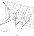
- Figure 1 is a drawing of the tip region of an electrostatic printhead 1 of the type described in this prior art, showing several ejection upstands 2 each with a tip 21. Between each ejection upstand is a wall 3, also called a cheek, which defines the boundary of each ejection cell. In each cell, ink flows in the two channels 4, one on each side of the ejection upstand 2 and in use the ink meniscus is pinned between the top of the cheeks and the top of the ejection upstand. In this geometry the positive direction of the z-axis is defined as pointing from the substrate towards the printhead, the x-axis points along the line of the tips of the ejection upstands and the y-axis is perpendicular to these.
- Figure 2 is a schematic diagram in the x-z plane of a single ejection cell 5 in the same printhead 1, looking along the y-axis taking a slice through the middle of the tips of the upstands 2.
- This figure shows the cheeks 3, the ejection upstand 2, the ejection location 6, the location of the ejection electrodes 7 and the position of the ink meniscus 8.
- the solid arrow 9 shows the ejection direction and also points towards the substrate.
- the pitch between the ejection cells is 168 ⁇ m.
- the ink usually flows into the page, away from the reader.
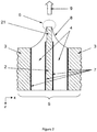
- Figure 3 is a schematic diagram of the same printhead 1 in the y-z plane showing a side-on view of an ejection upstand along the x-axis.
- This figure shows the ejection upstand 2, the location of the electrode 7 on the upstand and a component known as an intermediate electrode (10).
- the intermediate electrode 10 is a structure that has electrodes 101, on its inner face (and sometimes over its entire surface), that in use are biased to a different potential from that of the ejection electrodes 7 on the ejection upstands 2.
- the intermediate electrode 10 may be patterned so that each ejection upstand 2 has an electrode facing it that can be individually addressed, or it can be uniformly metallised such that the whole surface of the intermediate electrode 10 is held at a constant bias.
- the intermediate electrode 10 acts as an electrostatic shield by screening the ejection location from external electric fields and allows the electric field at the ejection location 6 to be carefully controlled.
- the solid arrow 11 shows the ejection direction and again points in the direction of the substrate.
- the ink usually flows from left to right.
- V B a voltage, V IE , between the intermediate electrode 10 and the substrate.
- V IE a voltage, V IE + V B .
- the magnitude of V B is chosen such that an electric field is generated at the ejection location 6 that concentrates the particles, but does not eject the particles. Ejection spontaneously occurs at applied biases of V B above a certain threshold voltage, V S , corresponding to the electric field strength at which the electrophoretic force on the particles exactly balances the surface tension of the ink. It is therefore always the case that V B is selected to be less than V S .
- V B Upon application of V B , the ink meniscus moves forwards to cover more of the ejection upstand 2.
- a further voltage pulse of amplitude V P is applied to the ejection upstand 2, such that the potential difference between the ejection upstand 2 and the intermediate electrode 10 is V B +V P . Ejection will continue for the duration of the voltage pulse.
- One of the advantages of electrostatic printers of this type is that greyscale printing can be achieved by modulating either the duration or the amplitude of the voltage pulse.
- the voltage pulses may be generated such that the amplitude of individual pulses are derived from the bitmap data, or such that the pulse duration is derived from the bitmap data, or using a combination of both techniques.
- Electrostatic printers of the type described herein eject more viscous jets of particulate material from a less viscous carrier fluid. This offers many advantages over conventional digital printers based on piezoelectric or thermal technology including substrate independence, i.e. the ability to print onto absorbing and non-absorbing substrates without material spreading after impact, smaller dot diameters, improved dot formation (leading to a reduced number of satellite droplets), greyscale printing and compatibility with a wide range of materials.
- electrostatic printers described herein are increased reliability. This may be due to the fact that there are no moving parts or that there is a very open structure (no small nozzles), which results in fewer blockages. Further, recirculating ink helps keep ink channels clear and particles suspended. These electrostatic printers are also low cost, as the uncomplicated printhead structure can be made using simple manufacturing techniques
- Printheads comprising any number of ejectors can be constructed for use in the invention by fabricating numerous cells 5, of the type shown in Figures 1 to 3 , side-by-side along the x-axis.
- a controlling computer converts image data (bit-mapped pixel values) stored in its memory into voltage waveforms (commonly digital square pulses) that are supplied to each channel individually.
- image data bit-mapped pixel values
- voltage waveforms commonly digital square pulses
- a layer of pigment (marking particles) is fixed to a substrate.
- the layer of pigment is coated with a varnish, for example: Hyperion Technology Varnish (product code 12104 XWH water-based varnish from Sun Chemical), or a varnish comprising styrene-acrylic based copolymer dispersed in slightly alkaline water, which is then cured.
- the varnish can be put down by a contact or non-contact process and the curing system for the varnish may be via carrier evaporation or a thermal, chemical, UV or electron-beam cure as appropriate for the chosen varnish.
- varnishes are: PPG8241-801/B and Valspar 2228005 thermal curing varnishes for metal; SunCure 15HC146 or 13HC143 UV-curing over-print varnish from Sun Chemical; Sunprop RB600 solvent-based lacquer also from Sun Chemical.
- the surface of the substrate is pre-coated with a basecoat material before printing, the basecoat being in an uncured or partially cured state when the layers of pigment are deposited onto it by the printheads.
- the pigments are then fixed to the substrate by curing the basecoat using a method suitable for the chosen basecoat, after all the pigments have been deposited.
- a process of the invention includes printing onto a non-absorbent substrate.
- non-absorbent means that the substrate takes up less than 50% of the applied carrier liquid.
- the dry ink thickness can be very thin (less than 1 micron) as it consists almost totally of pigment, and therefore there is no visible surface relief or texture that results from the printing process.
- the process requires such a small volume of ink, the time and energy required to dry the wet ink before varnishing is reduced.
- the small volume of ink required means there is less solvent involved in the printing process and less solvent to be evaporated or recycled.
- the invention also ensures a uniform finish (in terms of gloss, etc.), as the varnish can be applied to both the printed and unprinted areas of material, enhancing its visual appearance compared with a printing method where the inks and substrate have different visual properties.
- magenta Yellow, magenta, cyan and black inks were prepared for use in the invention.
- the formula for the magenta ink was as follows: Pigment PR 57:1 Permanent Rubine from Clariant 100 g Dispersant Solsperse S17000 6 g Carrier liquid Isopar G to 500 g
- the other three inks were prepared by a similar method.
- the four inks were printed sequentially from four printheads of the type described in WO93/11866 , WO97/27058 , WO97/27056 , WO98/32609 , WO01/30576 and WO03/101741 , onto a white base-coated metal substrate moving at a speed of 1 m/s relative to the printheads.
- the width of each printhead was 172mm and the width of the print formed on the substrate from the printheads was 160mm.
- the image was a four-colour design incorporating text, graphics and photographic elements and having a resolution of 600 pixels per inch.
- Each colour separation was formed from four passes of the substrate under the printhead, which had an ejector spacing of 150 ejectors per inch, the four passes taking a total of 0.8 seconds, with a time interval of 0.2 seconds between finishing the printing of one colour and starting the printing of the next.
- the printed substrate was dried using a combination of heating and airflow for one second (to evaporate residual carrier liquid from the print).
- a thermally-curing, water-based varnish was applied to the printed substrate using an anilox roller, and cured by heating to 200 °C for five minutes. This gave a high level of fix, gloss and chemical and abrasion resistance to the printed material.
- the four inks were printed sequentially from four printheads of the type described in WO93/11866 , WO97/27058 , WO97/27056 , WO98/32609 , WO01/30576 and WO03/101741 , onto a clear, 12 micron thick, PET (polyethylene terephthalate) film.
- the PET film measuring approximately 200 mm by 300 mm, was mounted on a flat, horizontal, metal platen positioned approximately 0.5 mm beneath the printheads. The platen was controlled to move relative to the printheads repeatedly to and fro at a speed of 0.8 metres per second in a direction perpendicular to the printhead arrays.
- the image to be printed was a 600 dot-per-inch, colour design incorporating text, graphics and photographic images, measuring 100 mm by 160 mm.
- Each printhead was 100 mm wide and had an ejector spacing of 168 microns, such that four passes of the substrate beneath a given printhead created a 600 dot-per-inch, single colour separation of the printed image, each pass being offset by 42 microns from the previous pass.
- one printhead at a time was controlled to print during each forward motion of the platen and, on each return pass of the platen, the printhead was controlled to move perpendicular to the substrate motion by a distance of 42 microns.
- the colour image was printed onto the PET film by printing each of the four colour separations in the manner described above, sequentially, with a period of 30 seconds between the printing of each colour separation to allow the residual carrier liquid in the print to evaporate. Each colour separation took approximately 4 seconds to print, and there was no intermediate fixing between colours. Once all four colours had been printed, the printed image was fixed using Lukas Spray Film Gloss, number 2321, solvent based acrylic resin and allowed to air-dry. The resultant print on the PET film was near photographic quality with a high level of fix, gloss and chemical and abrasion resistance.
Landscapes
- Chemical & Material Sciences (AREA)
- Engineering & Computer Science (AREA)
- Life Sciences & Earth Sciences (AREA)
- Materials Engineering (AREA)
- Wood Science & Technology (AREA)
- Organic Chemistry (AREA)
- Physics & Mathematics (AREA)
- Plasma & Fusion (AREA)
- Ink Jet Recording Methods And Recording Media Thereof (AREA)
- Inks, Pencil-Leads, Or Crayons (AREA)
- Ink Jet (AREA)
- Application Of Or Painting With Fluid Materials (AREA)
- Particle Formation And Scattering Control In Inkjet Printers (AREA)
Priority Applications (2)
| Application Number | Priority Date | Filing Date | Title |
|---|---|---|---|
| EP10755134.3A EP2478063B1 (en) | 2009-09-15 | 2010-09-14 | Printing process and liquid ink jet ink |
| PL10755134T PL2478063T3 (pl) | 2009-09-15 | 2010-09-14 | Proces drukowania i ciekły atrament do drukarek atramentowych |
Applications Claiming Priority (3)
| Application Number | Priority Date | Filing Date | Title |
|---|---|---|---|
| EP09170296 | 2009-09-15 | ||
| PCT/EP2010/063472 WO2011032939A1 (en) | 2009-09-15 | 2010-09-14 | Printing process and liquid ink jet ink |
| EP10755134.3A EP2478063B1 (en) | 2009-09-15 | 2010-09-14 | Printing process and liquid ink jet ink |
Publications (2)
| Publication Number | Publication Date |
|---|---|
| EP2478063A1 EP2478063A1 (en) | 2012-07-25 |
| EP2478063B1 true EP2478063B1 (en) | 2020-06-03 |
Family
ID=41728065
Family Applications (1)
| Application Number | Title | Priority Date | Filing Date |
|---|---|---|---|
| EP10755134.3A Active EP2478063B1 (en) | 2009-09-15 | 2010-09-14 | Printing process and liquid ink jet ink |
Country Status (10)
| Country | Link |
|---|---|
| US (1) | US9156256B2 (ko) |
| EP (1) | EP2478063B1 (ko) |
| JP (3) | JP2013504462A (ko) |
| KR (2) | KR20120082408A (ko) |
| CN (1) | CN102597133B (ko) |
| AU (1) | AU2010297367B2 (ko) |
| ES (1) | ES2803244T3 (ko) |
| PL (1) | PL2478063T3 (ko) |
| PT (1) | PT2478063T (ko) |
| WO (1) | WO2011032939A1 (ko) |
Families Citing this family (15)
| Publication number | Priority date | Publication date | Assignee | Title |
|---|---|---|---|---|
| JP5891602B2 (ja) | 2011-04-28 | 2016-03-23 | 東洋製罐株式会社 | インクジェット印刷装置及びこれを用いたシームレス缶の印刷方法 |
| CN102303461A (zh) * | 2011-07-11 | 2012-01-04 | 广州南鸥卫浴用品有限公司 | 一种金属表面图案印刷工艺 |
| US11673155B2 (en) | 2012-12-27 | 2023-06-13 | Kateeva, Inc. | Techniques for arrayed printing of a permanent layer with improved speed and accuracy |
| KR20190123811A (ko) | 2012-12-27 | 2019-11-01 | 카티바, 인크. | 정밀 공차 내로 유체를 증착하기 위한 인쇄 잉크 부피 제어를 위한 기법 |
| EP2805826A1 (en) * | 2013-05-20 | 2014-11-26 | Tonejet Limited | Printhead calibration and printing |
| JP6910327B2 (ja) * | 2013-06-27 | 2021-07-28 | トーンジェット リミテッド | プリントヘッドの制御 |
| KR102182788B1 (ko) | 2013-12-12 | 2020-11-25 | 카티바, 인크. | 두께를 제어하기 위해 하프토닝을 이용하는 잉크-기반 층 제조 |
| NL2012603B1 (en) | 2014-04-10 | 2016-05-09 | Xeikon Ip Bv | A method of digitally printing and a digital printing apparatus. |
| GB201407440D0 (en) * | 2014-04-28 | 2014-06-11 | Tonejet Ltd | Printing on cylindrical objects |
| JP6485183B2 (ja) * | 2015-04-17 | 2019-03-20 | セイコーエプソン株式会社 | 印刷装置 |
| US20220203709A1 (en) | 2019-04-26 | 2022-06-30 | Tonejet Limited | Apparatus and method for preparing a cylindrical object for decorating thereon |
| WO2021086326A1 (en) * | 2019-10-29 | 2021-05-06 | Hewlett-Packard Development Company, L.P. | Image formation device with radiation fixation |
| CN114312075B (zh) * | 2020-06-04 | 2023-09-19 | 中钞印制技术研究院有限公司 | 印码设备 |
| US11108353B1 (en) | 2020-07-14 | 2021-08-31 | FTC Solar, Inc. | Systems and methods for array level terrain based backtracking |
| CN113199867B (zh) * | 2021-04-12 | 2022-06-14 | 华中科技大学 | 一种电流体喷射图案化诱导方法与系统 |
Family Cites Families (34)
| Publication number | Priority date | Publication date | Assignee | Title |
|---|---|---|---|---|
| US3542682A (en) * | 1968-06-19 | 1970-11-24 | Gaf Corp | Liquid toners for electrostatic printing |
| US4165399A (en) | 1975-11-24 | 1979-08-21 | American Can Company | Binderless ink for jet printing |
| CN85101618A (zh) * | 1985-04-01 | 1986-08-20 | 机械工业部天津复印技术研究所 | 碳黑树脂静电调色剂及制造方法 |
| ATE185285T1 (de) | 1991-12-18 | 1999-10-15 | Tonejet Corp Pty Ltd | Methode und vorrichtung zur herstellung von diskreten agglomeraten von einem teilchenförmigen material |
| WO1995001404A1 (en) | 1993-07-01 | 1995-01-12 | Tonejet Corporation Pty. Ltd. | Liquid ink jet ink |
| GB9521673D0 (en) * | 1995-10-23 | 1996-01-03 | Xaar Ltd | Ink jet printer dispersion inks |
| GB9601226D0 (en) | 1996-01-22 | 1996-03-20 | The Technology Partnership Plc | Ejection apparatus and method |
| RU2142367C1 (ru) | 1996-01-22 | 1999-12-10 | Таунджет Корпорейшн ПТИ, Лтд | Эжекционное устройство для нанесения материала из жидкости |
| GB9701318D0 (en) | 1997-01-22 | 1997-03-12 | Tonejet Corp Pty Ltd | Ejection apparatus |
| GB9902386D0 (en) * | 1999-02-04 | 1999-03-24 | Zeneca Ltd | Printing inks |
| EP1095772A1 (en) | 1999-10-25 | 2001-05-02 | Tonejet Corporation Pty Ltd | Printhead |
| JP2002169470A (ja) * | 2000-11-27 | 2002-06-14 | Three M Innovative Properties Co | 印刷表示シートおよび印刷表示体 |
| JP2003276323A (ja) * | 2002-01-21 | 2003-09-30 | Seiko Epson Corp | インクジェット記録物及びその製造方法 |
| JP2003251908A (ja) | 2002-02-28 | 2003-09-09 | Konica Corp | インクジェット記録方法及び転写保護層 |
| EP1366901B1 (en) | 2002-05-31 | 2005-09-14 | Tonejet Limited | Printhead |
| JP2005138503A (ja) * | 2003-11-07 | 2005-06-02 | Ricoh Co Ltd | インクセット、画像形成装置、カートリッジ、記録物 |
| JP4051006B2 (ja) | 2003-06-19 | 2008-02-20 | 株式会社リコー | 記録材料及びそれを用いた画像形成方法 |
| JP2005017352A (ja) | 2003-06-23 | 2005-01-20 | Fuji Photo Film Co Ltd | フレキソ印刷版の製版方法 |
| JP4114794B2 (ja) * | 2003-06-30 | 2008-07-09 | サカタインクス株式会社 | 油性インクジェット記録用インク組成物 |
| JP2005035194A (ja) * | 2003-07-16 | 2005-02-10 | Toppan Forms Co Ltd | カード |
| JP2005059311A (ja) * | 2003-08-08 | 2005-03-10 | Seiko Epson Corp | 画像保護フィルム及びこれを用いた画像保護方法 |
| JP2005081754A (ja) * | 2003-09-10 | 2005-03-31 | Konica Minolta Holdings Inc | インクジェット記録方法及び記録物 |
| JP4362057B2 (ja) * | 2003-09-24 | 2009-11-11 | 富士フイルム株式会社 | インクジェットヘッドおよびインクジェット記録装置 |
| JP2005103958A (ja) | 2003-09-30 | 2005-04-21 | Fuji Photo Film Co Ltd | インクジェット記録方法 |
| US20050131101A1 (en) | 2003-10-03 | 2005-06-16 | Fuji Photo Film Co., Ltd. | Ink composition and inkjet recording method |
| US20060075917A1 (en) * | 2004-10-08 | 2006-04-13 | Edwards Paul A | Smooth finish UV ink system and method |
| US7977408B2 (en) | 2005-02-04 | 2011-07-12 | Ricoh Company, Ltd. | Recording ink, ink set, ink cartridge, ink record, inkjet recording apparatus and inkjet recording method |
| CN1827239A (zh) * | 2005-03-04 | 2006-09-06 | 海德堡印刷机械股份公司 | 用于对印刷物喷墨上漆的方法 |
| JP2006315363A (ja) * | 2005-05-16 | 2006-11-24 | Konica Minolta Holdings Inc | インクジェット記録方法 |
| US7571999B2 (en) * | 2005-11-30 | 2009-08-11 | Xerox Corporation | Overcoat compositions, oil-based ink compositions, and processes for ink-jet recording using overcoat and oil-based ink compositions |
| JP4983150B2 (ja) | 2006-04-28 | 2012-07-25 | 東洋インキScホールディングス株式会社 | 導電性被膜の製造方法 |
| EP1927632B1 (en) * | 2006-11-23 | 2010-08-18 | Agfa Graphics N.V. | Novel radiation curable compositions |
| JP2009149037A (ja) * | 2007-12-21 | 2009-07-09 | Tohoku Ricoh Co Ltd | インクジェット印刷装置におけるコーティング装置 |
| WO2011021591A1 (en) | 2009-08-21 | 2011-02-24 | Ricoh Company, Ltd. | Image forming method, and image formed matter |
-
2010
- 2010-09-14 KR KR1020127007033A patent/KR20120082408A/ko active Search and Examination
- 2010-09-14 ES ES10755134T patent/ES2803244T3/es active Active
- 2010-09-14 JP JP2012529237A patent/JP2013504462A/ja active Pending
- 2010-09-14 WO PCT/EP2010/063472 patent/WO2011032939A1/en active Application Filing
- 2010-09-14 PL PL10755134T patent/PL2478063T3/pl unknown
- 2010-09-14 CN CN201080040809.7A patent/CN102597133B/zh active Active
- 2010-09-14 US US13/261,214 patent/US9156256B2/en not_active Expired - Fee Related
- 2010-09-14 KR KR1020187005608A patent/KR101943281B1/ko active IP Right Grant
- 2010-09-14 AU AU2010297367A patent/AU2010297367B2/en not_active Ceased
- 2010-09-14 PT PT107551343T patent/PT2478063T/pt unknown
- 2010-09-14 EP EP10755134.3A patent/EP2478063B1/en active Active
-
2014
- 2014-09-29 JP JP2014198394A patent/JP2015057324A/ja active Pending
-
2016
- 2016-10-05 JP JP2016196926A patent/JP2017077728A/ja active Pending
Non-Patent Citations (1)
| Title |
|---|
| None * |
Also Published As
| Publication number | Publication date |
|---|---|
| WO2011032939A1 (en) | 2011-03-24 |
| JP2015057324A (ja) | 2015-03-26 |
| CN102597133B (zh) | 2018-10-19 |
| AU2010297367B2 (en) | 2013-08-22 |
| JP2013504462A (ja) | 2013-02-07 |
| PT2478063T (pt) | 2020-07-10 |
| US20120218362A1 (en) | 2012-08-30 |
| US9156256B2 (en) | 2015-10-13 |
| CN102597133A (zh) | 2012-07-18 |
| ES2803244T3 (es) | 2021-01-25 |
| KR20180026554A (ko) | 2018-03-12 |
| AU2010297367A1 (en) | 2012-03-15 |
| EP2478063A1 (en) | 2012-07-25 |
| KR101943281B1 (ko) | 2019-01-28 |
| KR20120082408A (ko) | 2012-07-23 |
| PL2478063T3 (pl) | 2020-11-16 |
| JP2017077728A (ja) | 2017-04-27 |
Similar Documents
| Publication | Publication Date | Title |
|---|---|---|
| EP2478063B1 (en) | Printing process and liquid ink jet ink | |
| CN101835622B (zh) | 适用于一表面的基于纳米粒子的选通剂 | |
| US10266715B2 (en) | Liquid composition, especially ink composition, for printing with a binary deflected continuous jet, with non-charged drops, use of said composition, marking method and marked substrate | |
| JP4951462B2 (ja) | 改善された画像耐久性をもたらすインクジェット印刷方法及びシステム | |
| US20010043260A1 (en) | Color printing apparatus and processes thereof | |
| CN100431843C (zh) | 喷墨打印方法和喷墨打印装置 | |
| US20100209677A1 (en) | Image recording method, record and image recording system | |
| US11072197B2 (en) | Method for manufacturing printed matter | |
| CN104890366A (zh) | 记录装置和记录方法 | |
| CN103358708A (zh) | 喷墨记录设备和喷墨记录方法 | |
| JP2001246741A (ja) | インクジェットプリントの印刷方法及びプリンタ用インキセット | |
| JPH091049A (ja) | 模様塗膜の形成方法 | |
| JP3559637B2 (ja) | 画像形成方法、インクセット、インク、インクの調製方法及びカラー画像の異色境界滲みの低減方法 | |
| JP2010167371A (ja) | 液体付与装置 | |
| JP2001081377A (ja) | インク、インクセット、インクカートリッジ、記録ユニット、画像記録装置及びインクジェット記録方法 | |
| EP0992552A1 (en) | Ink additive for jet orifice protection | |
| RU2005123818A (ru) | Краска на водной основе, способ струйного нанесения краски, катридж с краской, узел для нанесения краски, струйное устройство для нанесения краски и способ формирования изображений | |
| JP2002088290A (ja) | インクセット、インクジェット記録方法、カチオン性黒色インク、記録ユニット、インクカートリッジ及びインクジェット記録装置 | |
| US20200269623A1 (en) | Methods of printing on non-permeable surfaces | |
| JPH11105308A (ja) | 画像形成方法および画像形成装置 |
Legal Events
| Date | Code | Title | Description |
|---|---|---|---|
| PUAI | Public reference made under article 153(3) epc to a published international application that has entered the european phase |
Free format text: ORIGINAL CODE: 0009012 |
|
| 17P | Request for examination filed |
Effective date: 20120410 |
|
| AK | Designated contracting states |
Kind code of ref document: A1 Designated state(s): AL AT BE BG CH CY CZ DE DK EE ES FI FR GB GR HR HU IE IS IT LI LT LU LV MC MK MT NL NO PL PT RO SE SI SK SM TR |
|
| DAX | Request for extension of the european patent (deleted) | ||
| 17Q | First examination report despatched |
Effective date: 20140827 |
|
| STAA | Information on the status of an ep patent application or granted ep patent |
Free format text: STATUS: EXAMINATION IS IN PROGRESS |
|
| GRAP | Despatch of communication of intention to grant a patent |
Free format text: ORIGINAL CODE: EPIDOSNIGR1 |
|
| STAA | Information on the status of an ep patent application or granted ep patent |
Free format text: STATUS: GRANT OF PATENT IS INTENDED |
|
| INTG | Intention to grant announced |
Effective date: 20200102 |
|
| GRAS | Grant fee paid |
Free format text: ORIGINAL CODE: EPIDOSNIGR3 |
|
| GRAA | (expected) grant |
Free format text: ORIGINAL CODE: 0009210 |
|
| STAA | Information on the status of an ep patent application or granted ep patent |
Free format text: STATUS: THE PATENT HAS BEEN GRANTED |
|
| AK | Designated contracting states |
Kind code of ref document: B1 Designated state(s): AL AT BE BG CH CY CZ DE DK EE ES FI FR GB GR HR HU IE IS IT LI LT LU LV MC MK MT NL NO PL PT RO SE SI SK SM TR |
|
| REG | Reference to a national code |
Ref country code: GB Ref legal event code: FG4D |
|
| REG | Reference to a national code |
Ref country code: CH Ref legal event code: EP Ref country code: AT Ref legal event code: REF Ref document number: 1276995 Country of ref document: AT Kind code of ref document: T Effective date: 20200615 |
|
| REG | Reference to a national code |
Ref country code: DE Ref legal event code: R096 Ref document number: 602010064522 Country of ref document: DE |
|
| REG | Reference to a national code |
Ref country code: CH Ref legal event code: NV Representative=s name: VALIPAT S.A. C/O BOVARD SA NEUCHATEL, CH |
|
| REG | Reference to a national code |
Ref country code: PT Ref legal event code: SC4A Ref document number: 2478063 Country of ref document: PT Date of ref document: 20200710 Kind code of ref document: T Free format text: AVAILABILITY OF NATIONAL TRANSLATION Effective date: 20200703 |
|
| REG | Reference to a national code |
Ref country code: NL Ref legal event code: FP |
|
| REG | Reference to a national code |
Ref country code: LT Ref legal event code: MG4D |
|
| PG25 | Lapsed in a contracting state [announced via postgrant information from national office to epo] |
Ref country code: NO Free format text: LAPSE BECAUSE OF FAILURE TO SUBMIT A TRANSLATION OF THE DESCRIPTION OR TO PAY THE FEE WITHIN THE PRESCRIBED TIME-LIMIT Effective date: 20200903 Ref country code: GR Free format text: LAPSE BECAUSE OF FAILURE TO SUBMIT A TRANSLATION OF THE DESCRIPTION OR TO PAY THE FEE WITHIN THE PRESCRIBED TIME-LIMIT Effective date: 20200904 Ref country code: FI Free format text: LAPSE BECAUSE OF FAILURE TO SUBMIT A TRANSLATION OF THE DESCRIPTION OR TO PAY THE FEE WITHIN THE PRESCRIBED TIME-LIMIT Effective date: 20200603 Ref country code: SE Free format text: LAPSE BECAUSE OF FAILURE TO SUBMIT A TRANSLATION OF THE DESCRIPTION OR TO PAY THE FEE WITHIN THE PRESCRIBED TIME-LIMIT Effective date: 20200603 Ref country code: LT Free format text: LAPSE BECAUSE OF FAILURE TO SUBMIT A TRANSLATION OF THE DESCRIPTION OR TO PAY THE FEE WITHIN THE PRESCRIBED TIME-LIMIT Effective date: 20200603 |
|
| PG25 | Lapsed in a contracting state [announced via postgrant information from national office to epo] |
Ref country code: BG Free format text: LAPSE BECAUSE OF FAILURE TO SUBMIT A TRANSLATION OF THE DESCRIPTION OR TO PAY THE FEE WITHIN THE PRESCRIBED TIME-LIMIT Effective date: 20200903 Ref country code: HR Free format text: LAPSE BECAUSE OF FAILURE TO SUBMIT A TRANSLATION OF THE DESCRIPTION OR TO PAY THE FEE WITHIN THE PRESCRIBED TIME-LIMIT Effective date: 20200603 Ref country code: LV Free format text: LAPSE BECAUSE OF FAILURE TO SUBMIT A TRANSLATION OF THE DESCRIPTION OR TO PAY THE FEE WITHIN THE PRESCRIBED TIME-LIMIT Effective date: 20200603 |
|
| PG25 | Lapsed in a contracting state [announced via postgrant information from national office to epo] |
Ref country code: AL Free format text: LAPSE BECAUSE OF FAILURE TO SUBMIT A TRANSLATION OF THE DESCRIPTION OR TO PAY THE FEE WITHIN THE PRESCRIBED TIME-LIMIT Effective date: 20200603 |
|
| REG | Reference to a national code |
Ref country code: ES Ref legal event code: FG2A Ref document number: 2803244 Country of ref document: ES Kind code of ref document: T3 Effective date: 20210125 |
|
| PG25 | Lapsed in a contracting state [announced via postgrant information from national office to epo] |
Ref country code: EE Free format text: LAPSE BECAUSE OF FAILURE TO SUBMIT A TRANSLATION OF THE DESCRIPTION OR TO PAY THE FEE WITHIN THE PRESCRIBED TIME-LIMIT Effective date: 20200603 Ref country code: SM Free format text: LAPSE BECAUSE OF FAILURE TO SUBMIT A TRANSLATION OF THE DESCRIPTION OR TO PAY THE FEE WITHIN THE PRESCRIBED TIME-LIMIT Effective date: 20200603 Ref country code: RO Free format text: LAPSE BECAUSE OF FAILURE TO SUBMIT A TRANSLATION OF THE DESCRIPTION OR TO PAY THE FEE WITHIN THE PRESCRIBED TIME-LIMIT Effective date: 20200603 Ref country code: CZ Free format text: LAPSE BECAUSE OF FAILURE TO SUBMIT A TRANSLATION OF THE DESCRIPTION OR TO PAY THE FEE WITHIN THE PRESCRIBED TIME-LIMIT Effective date: 20200603 |
|
| PG25 | Lapsed in a contracting state [announced via postgrant information from national office to epo] |
Ref country code: SK Free format text: LAPSE BECAUSE OF FAILURE TO SUBMIT A TRANSLATION OF THE DESCRIPTION OR TO PAY THE FEE WITHIN THE PRESCRIBED TIME-LIMIT Effective date: 20200603 Ref country code: IS Free format text: LAPSE BECAUSE OF FAILURE TO SUBMIT A TRANSLATION OF THE DESCRIPTION OR TO PAY THE FEE WITHIN THE PRESCRIBED TIME-LIMIT Effective date: 20201003 |
|
| REG | Reference to a national code |
Ref country code: DE Ref legal event code: R097 Ref document number: 602010064522 Country of ref document: DE |
|
| PLBE | No opposition filed within time limit |
Free format text: ORIGINAL CODE: 0009261 |
|
| STAA | Information on the status of an ep patent application or granted ep patent |
Free format text: STATUS: NO OPPOSITION FILED WITHIN TIME LIMIT |
|
| PG25 | Lapsed in a contracting state [announced via postgrant information from national office to epo] |
Ref country code: MC Free format text: LAPSE BECAUSE OF FAILURE TO SUBMIT A TRANSLATION OF THE DESCRIPTION OR TO PAY THE FEE WITHIN THE PRESCRIBED TIME-LIMIT Effective date: 20200603 Ref country code: DK Free format text: LAPSE BECAUSE OF FAILURE TO SUBMIT A TRANSLATION OF THE DESCRIPTION OR TO PAY THE FEE WITHIN THE PRESCRIBED TIME-LIMIT Effective date: 20200603 |
|
| 26N | No opposition filed |
Effective date: 20210304 |
|
| PG25 | Lapsed in a contracting state [announced via postgrant information from national office to epo] |
Ref country code: SI Free format text: LAPSE BECAUSE OF FAILURE TO SUBMIT A TRANSLATION OF THE DESCRIPTION OR TO PAY THE FEE WITHIN THE PRESCRIBED TIME-LIMIT Effective date: 20200603 |
|
| PG25 | Lapsed in a contracting state [announced via postgrant information from national office to epo] |
Ref country code: LU Free format text: LAPSE BECAUSE OF NON-PAYMENT OF DUE FEES Effective date: 20200914 |
|
| PG25 | Lapsed in a contracting state [announced via postgrant information from national office to epo] |
Ref country code: IE Free format text: LAPSE BECAUSE OF NON-PAYMENT OF DUE FEES Effective date: 20200914 |
|
| PGFP | Annual fee paid to national office [announced via postgrant information from national office to epo] |
Ref country code: NL Payment date: 20210915 Year of fee payment: 12 Ref country code: AT Payment date: 20210825 Year of fee payment: 12 |
|
| PGFP | Annual fee paid to national office [announced via postgrant information from national office to epo] |
Ref country code: BE Payment date: 20210916 Year of fee payment: 12 Ref country code: PL Payment date: 20210827 Year of fee payment: 12 |
|
| PGFP | Annual fee paid to national office [announced via postgrant information from national office to epo] |
Ref country code: PT Payment date: 20210907 Year of fee payment: 12 |
|
| PGFP | Annual fee paid to national office [announced via postgrant information from national office to epo] |
Ref country code: ES Payment date: 20211005 Year of fee payment: 12 |
|
| PG25 | Lapsed in a contracting state [announced via postgrant information from national office to epo] |
Ref country code: TR Free format text: LAPSE BECAUSE OF FAILURE TO SUBMIT A TRANSLATION OF THE DESCRIPTION OR TO PAY THE FEE WITHIN THE PRESCRIBED TIME-LIMIT Effective date: 20200603 Ref country code: MT Free format text: LAPSE BECAUSE OF FAILURE TO SUBMIT A TRANSLATION OF THE DESCRIPTION OR TO PAY THE FEE WITHIN THE PRESCRIBED TIME-LIMIT Effective date: 20200603 Ref country code: CY Free format text: LAPSE BECAUSE OF FAILURE TO SUBMIT A TRANSLATION OF THE DESCRIPTION OR TO PAY THE FEE WITHIN THE PRESCRIBED TIME-LIMIT Effective date: 20200603 |
|
| PG25 | Lapsed in a contracting state [announced via postgrant information from national office to epo] |
Ref country code: MK Free format text: LAPSE BECAUSE OF FAILURE TO SUBMIT A TRANSLATION OF THE DESCRIPTION OR TO PAY THE FEE WITHIN THE PRESCRIBED TIME-LIMIT Effective date: 20200603 |
|
| PGFP | Annual fee paid to national office [announced via postgrant information from national office to epo] |
Ref country code: IT Payment date: 20220829 Year of fee payment: 13 Ref country code: GB Payment date: 20220818 Year of fee payment: 13 Ref country code: DE Payment date: 20220609 Year of fee payment: 13 |
|
| PGFP | Annual fee paid to national office [announced via postgrant information from national office to epo] |
Ref country code: FR Payment date: 20220822 Year of fee payment: 13 |
|
| PGFP | Annual fee paid to national office [announced via postgrant information from national office to epo] |
Ref country code: CH Payment date: 20220901 Year of fee payment: 13 |
|
| PG25 | Lapsed in a contracting state [announced via postgrant information from national office to epo] |
Ref country code: PT Free format text: LAPSE BECAUSE OF NON-PAYMENT OF DUE FEES Effective date: 20230314 |
|
| REG | Reference to a national code |
Ref country code: NL Ref legal event code: MM Effective date: 20221001 |
|
| REG | Reference to a national code |
Ref country code: AT Ref legal event code: MM01 Ref document number: 1276995 Country of ref document: AT Kind code of ref document: T Effective date: 20220914 |
|
| REG | Reference to a national code |
Ref country code: BE Ref legal event code: MM Effective date: 20220930 |
|
| REG | Reference to a national code |
Ref country code: AT Ref legal event code: UEP Ref document number: 1276995 Country of ref document: AT Kind code of ref document: T Effective date: 20200603 |
|
| PG25 | Lapsed in a contracting state [announced via postgrant information from national office to epo] |
Ref country code: NL Free format text: LAPSE BECAUSE OF NON-PAYMENT OF DUE FEES Effective date: 20221001 |
|
| PG25 | Lapsed in a contracting state [announced via postgrant information from national office to epo] |
Ref country code: AT Free format text: LAPSE BECAUSE OF NON-PAYMENT OF DUE FEES Effective date: 20220914 |
|
| PG25 | Lapsed in a contracting state [announced via postgrant information from national office to epo] |
Ref country code: BE Free format text: LAPSE BECAUSE OF NON-PAYMENT OF DUE FEES Effective date: 20220930 |
|
| REG | Reference to a national code |
Ref country code: ES Ref legal event code: FD2A Effective date: 20231027 |
|
| PG25 | Lapsed in a contracting state [announced via postgrant information from national office to epo] |
Ref country code: PL Free format text: LAPSE BECAUSE OF NON-PAYMENT OF DUE FEES Effective date: 20220914 |
|
| PG25 | Lapsed in a contracting state [announced via postgrant information from national office to epo] |
Ref country code: ES Free format text: LAPSE BECAUSE OF NON-PAYMENT OF DUE FEES Effective date: 20220915 |
|
| PG25 | Lapsed in a contracting state [announced via postgrant information from national office to epo] |
Ref country code: ES Free format text: LAPSE BECAUSE OF NON-PAYMENT OF DUE FEES Effective date: 20220915 |
|
| REG | Reference to a national code |
Ref country code: DE Ref legal event code: R119 Ref document number: 602010064522 Country of ref document: DE |
|
| REG | Reference to a national code |
Ref country code: CH Ref legal event code: PL |
|
| GBPC | Gb: european patent ceased through non-payment of renewal fee |
Effective date: 20230914 |