EP2472548B1 - Shape memory alloy actuated circuit breaker - Google Patents
Shape memory alloy actuated circuit breaker Download PDFInfo
- Publication number
- EP2472548B1 EP2472548B1 EP11194746.1A EP11194746A EP2472548B1 EP 2472548 B1 EP2472548 B1 EP 2472548B1 EP 11194746 A EP11194746 A EP 11194746A EP 2472548 B1 EP2472548 B1 EP 2472548B1
- Authority
- EP
- European Patent Office
- Prior art keywords
- circuit breaker
- memory alloy
- shape memory
- holding member
- disposed
- Prior art date
- Legal status (The legal status is an assumption and is not a legal conclusion. Google has not performed a legal analysis and makes no representation as to the accuracy of the status listed.)
- Active
Links
- 229910001285 shape-memory alloy Inorganic materials 0.000 title claims description 107
- 230000004044 response Effects 0.000 claims description 19
- 230000008859 change Effects 0.000 claims description 10
- 230000007246 mechanism Effects 0.000 description 13
- 239000004020 conductor Substances 0.000 description 8
- 238000010438 heat treatment Methods 0.000 description 8
- 230000000694 effects Effects 0.000 description 7
- 239000000463 material Substances 0.000 description 6
- 230000006870 function Effects 0.000 description 5
- 238000006073 displacement reaction Methods 0.000 description 4
- 230000004913 activation Effects 0.000 description 3
- 230000006978 adaptation Effects 0.000 description 3
- 238000000034 method Methods 0.000 description 3
- 238000000926 separation method Methods 0.000 description 3
- 230000009466 transformation Effects 0.000 description 3
- RYGMFSIKBFXOCR-UHFFFAOYSA-N Copper Chemical compound [Cu] RYGMFSIKBFXOCR-UHFFFAOYSA-N 0.000 description 2
- 229910045601 alloy Inorganic materials 0.000 description 2
- 239000000956 alloy Substances 0.000 description 2
- 238000005219 brazing Methods 0.000 description 2
- 238000011084 recovery Methods 0.000 description 2
- 238000003466 welding Methods 0.000 description 2
- HZEWFHLRYVTOIW-UHFFFAOYSA-N [Ti].[Ni] Chemical compound [Ti].[Ni] HZEWFHLRYVTOIW-UHFFFAOYSA-N 0.000 description 1
- 230000004075 alteration Effects 0.000 description 1
- 230000004323 axial length Effects 0.000 description 1
- 238000004891 communication Methods 0.000 description 1
- 229920001940 conductive polymer Polymers 0.000 description 1
- 239000010949 copper Substances 0.000 description 1
- 229910052802 copper Inorganic materials 0.000 description 1
- 230000003111 delayed effect Effects 0.000 description 1
- 230000007717 exclusion Effects 0.000 description 1
- 229910000734 martensite Inorganic materials 0.000 description 1
- 230000003446 memory effect Effects 0.000 description 1
- 238000013021 overheating Methods 0.000 description 1
- 230000008569 process Effects 0.000 description 1
- 230000002035 prolonged effect Effects 0.000 description 1
- 230000000452 restraining effect Effects 0.000 description 1
- 230000000717 retained effect Effects 0.000 description 1
- 238000005476 soldering Methods 0.000 description 1
- 230000000007 visual effect Effects 0.000 description 1
- 238000004804 winding Methods 0.000 description 1
Images


Classifications
-
- H—ELECTRICITY
- H01—ELECTRIC ELEMENTS
- H01H—ELECTRIC SWITCHES; RELAYS; SELECTORS; EMERGENCY PROTECTIVE DEVICES
- H01H71/00—Details of the protective switches or relays covered by groups H01H73/00 - H01H83/00
- H01H71/10—Operating or release mechanisms
- H01H71/12—Automatic release mechanisms with or without manual release
- H01H71/14—Electrothermal mechanisms
- H01H71/145—Electrothermal mechanisms using shape memory materials
Definitions
- the field of the invention relates to circuit breakers generally, and more particularly to certain new and useful advances in circuit breakers having a thermal overload release trip system, of which the following is a specification, reference being had to the drawings accompanying and forming a part of the same.
- GB-A-2 026 246 concerns an electrical circuit breaker comprising a helical spring of shape memory effect material (SME) operatively acting on an armature arranged to cause tripping of the circuit breaker.
- SME shape memory effect material
- the SME spring is retained within a cage and is secured to the armature. When an electrical overload current passes through the SME spring, the SME spring contracts axially to trip the circuit breaker.
- DE-U1-94 05 745 concerns a trigger system for a circuit breaker comprising a thermal system including an element of a shape memory alloy implemented within a magnetic trigger system.
- JP-A-05 074309 concerns a circuit breaker comprising a coil portion of a shape memory alloy that is directly heated by an overcurrent in a circuit.
- a temperature of the alloy reaches a transformation temperature, a contracting force of the alloy overcomes a restraining force of springs that causes a separation of the circuit breaker contacts.
- Circuit breakers having one or more poles are well known electrical devices.
- the function of a circuit breaker is to electrically engage and disengage a selected monitored circuit from an electrical power supply.
- Circuit breakers are intended to provide protection in electrical circuits and distribution systems against electrical faults, such as prolonged electrical overload conditions and short-circuit fault currents, by providing automatic current interruption to the monitored circuit when the fault conditions occur.
- the protection function is accomplished by directing a current from the monitored circuit through a primary current path through each pole of the circuit breaker and, in response to a detected fault condition, rapidly tripping, i.e., releasing a mechanical latching of an operating mechanism to separate a pair of electrical contacts into a "tripped" OFF position thereby breaking the circuit.
- Such conventional circuit breakers typically include both a magnetic and a thermal overload release trip system to sense a fault or overload condition in the circuit and to trigger the tripping response.
- the thermal overload release type tripping system of conventional circuit breakers responds to electrical currents moderately above the circuit breaker's current rating by providing a delayed trip of the circuit breaker.
- the thermal overload release conventionally includes a thermally responsive conductive bimetal member that deflects in response to heating.
- a flexible conductor such as a braided copper wire, cooperates with the bimetal member and the circuit breaker mechanism to allow operative movement of the bimetal member along the circuit breaker current path.
- the bimetal is electrically connected in series with the primary current path through at least one circuit breaker pole and arranged to deflect in response to Joule effect heating, (i.e., caused by the electrical current through it).
- the bimetal is not disposed as part of the current path and is instead coupled to a heater, such as an inductive-type heater, which provides the current-generated heat to the bimetal.
- the circuit breaker bimetal deflects such that it causes a tripping mechanism that includes a spring-biased latch assembly to trigger the separation of a movable contact attached to a movable arm away from a stationary contact to a "tripped" OFF state.
- the bimetal is often configured and positioned such that the deflection of the bimetal drives a pivot arm, which in turn releases a latch.
- the latch will release to allow a stored energy device, such as a spring, to cause the separation of the contacts.
- the bimetal is connected in the primary current path through the circuit breaker pole and configured to deflect in response to Joule effect heating. In the event of a predetermined thermal condition, the bimetal contacts and displaces a trip bar.
- the bimetal is also electrically connected at the first end with the flexible conductor. The flexible conductor accommodates the operable movement of the bimetal on the on the primary current path.
- circuit breakers have used a bimetal that is not connected in the primary current path through the circuit breaker pole, but is instead heated by a separate heater element (not shown) that is not in the primary current path of the circuit breaker pole.
- bimetal controlled circuit breakers having a bimetal element connected in the primary conducting path of the circuit breaker is that the bimetal element may be overloaded by fault currents that are too high and thus consequently damaged and rendered inoperable.
- circuit breakers having indirectly heated bimetal elements i.e., not connected in series with the primary current path of the circuit breaker pole
- being heated by a separate heater element is that the heater represents an additional part having relatively complex geometry that must be provided and thus requires additional cost.
- Prior art circuit breakers have also employed a shape memory alloy (SMA) wire material, instead of a bimetal, as the thermally responsive element connected in the conducting path of circuit breakers to deflect in response to Joule effect heating.
- SMA shape memory alloy
- a thermally responsive element made of shape memory alloy of a first original shape is formed to a second selected shape, and then is heated, for example by the Joule effect, the member exerts a force in the direction which will bring its shape nearer to the first original shape via a phase transformation (the reversion transformation from the martensite phase to the parent phase). This force tending towards alteration of the second selected shape of the member towards a first original shape that it "remembers" can be utilized for driving a driven member in a desired direction.
- SMA shape memory alloy
- the SMA wire is formed into a particular shape, such as by winding into a coil, and the coil is then arranged to remember a first original shape in which it has a particular first length in its longitudinal direction.
- the coil is biased to have a particular second axial length, and then, when the coil is heated by the passage of an electric current through it, the coil tries to return to the original first length, thus exerting an actuation or tripping force in its longitudinal direction.
- At least one known problem with using a directly heated (i.e. heated by the Joule effect) SMA type temperature sensing member connected in series with the primary conducting path of the circuit breaker pole is that relatively large currents in the primary conductive path of the circuit breaker pole often result in damage to the SMA member response to high level current spikes, such as for example in the case of a short circuit condition.
- At least one known problem with using a directly heated SMA type temperature sensing member connected electrically in parallel with the primary conducting path of the circuit breaker pole is that, since a relatively high temperature is required to activate the SMA member, it is difficult to use arrange a secondary high-resistance current path in parallel with the primary conducting path that provides sufficient heat to reach the activation temperature of the SMA member, while simultaneously preventing overly high temperatures that would result in damage to the SMA member.
- Still another problem preventing use of using SMA members heated via the Joule effect is SMA materials are difficult to properly attach to other conductors via welding, brazing, or soldering without damaging the SMA material.
- At least one known problem preventing the use of indirectly heated (i.e. by a separate heating element) SMA type temperature sensing members is that, since a relatively high temperature is required to activate the SMA, it is difficult to use a separate heating element to provide sufficient heat to reach the activation temperature of the SMA member, while simultaneously preventing overly high temperatures that would result in damage to the SMA member and the heater.
- yet another problem preventing the use of an indirectly heated SMA type temperature sensing member is that the SMA member requires an additional element to hold, or otherwise support the SMA member.
- the present invention provides a thermal trip unit as defined in appended claim 1, a circuit breaker pole as defined in appended claim 8 and a circuit breaker as defined in appended claim 10.
- Embodiments of the invention provide a thermal trip unit for a circuit breaker, the circuit breaker including a primary conductive path for conducting a load current, comprising a shape memory alloy (SMA) member adapted to change from a first shape to a second shape at a predetermined thermal condition, a holding member configured and disposed to form a portion of the circuit breaker conductive path, said holding member arranged to at least partially enclose said SMA member, wherein said SMA member is configured and disposed within the circuit breaker to trigger a trip response of the circuit breaker at a predetermined thermal condition
- SMA shape memory alloy
- Embodiments of the invention also provide a circuit breaker, including a primary conductive path for conducting a load current, a thermal trip unit coupled to said primary conductive path, the circuit breaker comprising a shape memory alloy (SMA) member adapted to change from a first shape to a second shape at a predetermined thermal condition, a conductive holding member configured and disposed to form a portion of the circuit breaker conductive path, said holding member arranged to at least partially enclose said SMA member, wherein said SMA member is configured and disposed within the circuit breaker to trigger a trip response of the circuit breaker at the predetermined thermal condition.
- SMA shape memory alloy
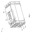
- FIG. 1 A configuration of an embodiment of a circuit breaker 311 is shown in FIG. 1 . It will be understood that while the embodiment of circuit breaker 311 as shown in FIG. 1 is of the three-pole type, other embodiments of circuit breakers 311 may have one or any number of poles as desired.
- the circuit breaker comprises a housing 314. A handle 313 protrudes through the housing 314 for manual operation of the circuit breaker 311. The position of handle 313 also provides a visual indication of one of several states of the circuit breaker 311 such as ON, OFF, or TRIPPED.
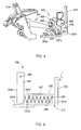
- FIG. 2 A configuration of a single pole 301 of an embodiment of a circuit breaker 311 in the ON state is shown in FIG. 2 with the housing 314 omitted for clarity.
- the circuit breaker contacts 322a, 323a, and 322b, 323b are closed which allows an electrical current to flow through a primary current path 312 of the circuit breaker pole 301.
- a TRIPPED state (not shown) of circuit breaker pole 301 may result from automatic activation of the a stored energy tripping mechanism 382 which causes an operating mechanism 331 to separate the contacts 322a, 323a, and 322b, 323b.
- the tripping mechanism 382 may trip in response to a level of current through circuit breaker pole 301 over a predetermined period of time that results in a predetermined thermal condition.
- the operating mechanism 331 typically in cooperation with the user-operated handle 313, is arranged to move the contact arm 321 such that each movable contact 322a, 322b is brought into latched engagement with the corresponding stationary contact 323a, 323b (i.e., to a "closed” ON state), and alternatively separated from the stationary contacts 323a, 323b (i.e., to an "open” OFF state).
- a rotor 320 is configured to movably support a conductive contact arm 321 which is configured to support movable contacts 322a, 322b.
- Rotor 320 is further configured and arranged to be rotated via the handle 313 through an operating mechanism 331.
- the primary current path 312 is arranged such that in operation, at least a majority of the current electrical current in circuit breaker pole 301 flows therethrough.
- primary current path 312 comprises conductive elements preferably electrically connected in series.
- these conductive elements which form the primary current path 312 are a line strap 318, a conductive holder 337, stationary contacts 323a, 323b and corresponding stationary contact supports 124a, 124b, the movable contact arm 321, movable contacts 322a, 322b, and a load connection strap 119.
- FIG. 3 illustrates more clearly the exemplary primary current path 312 of the circuit breaker pole 301 of Fig. 2 , with all non-current path elements, except rotor 320 and SMA member 334, removed for clarity.
- the rotor 320 is formed of a suitable material, such as a non-conductive polymer, and is configured to rotably support the movable contact arm 321 including the movable contacts 322a, 322b.
- a conventional connection lug may be used to couple line side conductors such as cables (not shown) to the line side connection strap 318.
- Line strap 318 is in turn electrically connected in series with the conductive holder 337, line side stationary contact support 324a, stationary contact 323a, movable contact 322a, contact arm 321, movable contact 322b, stationary contact 323b, load side stationary contact support 324b, and the load side connection strap 319.
- a conductive element 333a may be provided in series with the primary conductive path 312 to couple the line side connection strap 318 to holder 337.
- the line side connection strap 318 may be directly connected to holder 337.
- a conductive element 333b may be provided in series with the primary conductive path 312 to couple the line side holder 337 to the load side stationary contact support 324b.
- the holder 337 may be directly connected to the load side stationary contact support 324b.
- Load strap 319 may also support a conventional connection lug (not shown) to enable a connection to load side conductors such as cables (not shown).
- the conductive holder 337 is electrically connected in series with and forms a portion of the primary conductive path 312.
- a thermal trip unit 330 comprises a SMA member 334 arranged to cooperate with a stored energy tripping mechanism 382 to trigger a trip response of the circuit breaker pole 301.
- the (SMA) member 334 of thermal trip unit 330 is adapted to change from a first shape to a second shape at a predetermined thermal condition, and further configured and disposed to trigger a trip response of the circuit breaker pole 301 by moving a trip bar 352 to activate the stored energy tripping mechanism 382 in the event of the predetermined thermal condition.
- the predetermined thermal condition may be caused by a predetermined current level through the circuit breaker pole 301 over a predetermined period of time.
- SMA member 334 is of a coil shape, preferably having a first end 334a and a second end 334b, and is adapted to elongate at the predetermined thermal condition.
- the SMA member 334 may also be configured in any number of first shapes, and may be adapted to change to any number of second shapes in the event of the predetermined thermal condition.
- a spring 351 biases a first end 352a of the trip bar 352.
- the first end 352a of the trip bar 352 is disposed proximal to the first end 334a of the SMA member 334.
- Trip bar 352 is configured for rotational displacement around an axis 354 located at a second end 352b in response to a displacement force from the SMA member 334 sufficient to overcome the bias force of spring 351.
- the rotation of trip bar 352 causes a primary latch member 363 to release or de-latch from a secondary latch member 365.
- the release of the primary and secondary latches 354, 363 releases the stored energy tripping mechanism 382 to trip the circuit breaker 311, opening the contacts to the "TRIPPED" off state.
- Holder 337 is formed of a suitable conductive material such as hardened copper and arranged to support and at least partially enclose said SMA member 334.
- the material forming SMA member 334 is selected to have sufficiently high impedance relative to the impedance of conductive holder 337 such that substantially no current flows through the SMA member 334.
- SMA member 334 is formed of nickel titanium (NiTi).
- holder 337 is formed as a hollow cylinder or tube comprising a conductive cylindrical wall surface 336, defining a tubular cavity 338, a first open end 337a, and a second closed end 334b.
- Holder 337 is disposed electrically in series with the primary current path 312 and configured to operatively support and at least partially enclose the SMA member 334, such as an SMA member 334 that is formed of a coil shape.
- the primary current path 312 is arranged to substantially limit a current flow through the SMA member.
- SMA member 334 When heating of SMA member 334 attains a predetermined thermal condition, such as a predetermined temperature, SMA member 334 generates a shape recovery force and changes from a first stressed state to a second stressed state whereby at least a portion of SMA member 334 operatively passes through the open end 337b of holder 337 to trigger the trip bar 352 thus tripping the circuit breaker 311.
- a predetermined thermal condition such as a predetermined temperature
- SMA member 334 in the event of the predetermined thermal condition, such as a predetermined temperature of SMA member 334, SMA member 334 exhibits a shape recovery force and changes from a first relatively compressed coil shape to a second relatively elongated coil shape whereby at least a portion of SMA member 334 operatively passes through the open end 337b of holder 337 to contact the trip bar 352 to trigger a trip of the circuit breaker 311.
- holder 337 may be configured having a wide range of dimensions and cross sections, such as for example the length of holder 337 or the volume of cavity 338 may be varied to provide a desired thermal condition at a predetermined current.
- an additional conductive tube 347 is electrically connected to and disposed within the tubular cavity 338 of holding member 337 and further disposed at least partially within the inside diameter of the SMA member 334 coil.
Applications Claiming Priority (1)
| Application Number | Priority Date | Filing Date | Title |
|---|---|---|---|
| US12/982,226 US8830026B2 (en) | 2010-12-30 | 2010-12-30 | Shape memory alloy actuated circuit breaker |
Publications (2)
| Publication Number | Publication Date |
|---|---|
| EP2472548A1 EP2472548A1 (en) | 2012-07-04 |
| EP2472548B1 true EP2472548B1 (en) | 2015-07-29 |
Family
ID=45375235
Family Applications (1)
| Application Number | Title | Priority Date | Filing Date |
|---|---|---|---|
| EP11194746.1A Active EP2472548B1 (en) | 2010-12-30 | 2011-12-21 | Shape memory alloy actuated circuit breaker |
Country Status (4)
| Country | Link |
|---|---|
| US (1) | US8830026B2 (ja) |
| EP (1) | EP2472548B1 (ja) |
| JP (1) | JP6068796B2 (ja) |
| CN (1) | CN102568955B (ja) |
Families Citing this family (16)
| Publication number | Priority date | Publication date | Assignee | Title |
|---|---|---|---|---|
| US9543103B2 (en) * | 2011-12-22 | 2017-01-10 | GM Global Technology Operations LLC | Activation of human-protecting safety mechanisms using smart materials |
| KR101574521B1 (ko) * | 2014-03-18 | 2015-12-04 | 한국과학기술연구원 | 계층구조를 이용하여 내재된 형태를 가지는 형태변환소재 및 이를 포함하는 전극 |
| EP3284100B1 (en) * | 2015-04-14 | 2023-04-05 | Safran Electrical & Power | Electrically controlled switching device including shape memory alloy element and method of operating |
| CN105729783B (zh) * | 2016-03-22 | 2017-09-12 | 杨丽 | 变压器修补用记忆树脂及其固化装置 |
| DE102016208930A1 (de) * | 2016-05-24 | 2017-11-30 | Siemens Aktiengesellschaft | Überlastauslöser |
| CN107808804B (zh) * | 2017-12-05 | 2019-04-12 | 中国石油大学(华东) | 磁性形状记忆合金断路器 |
| US10468218B2 (en) * | 2018-01-19 | 2019-11-05 | ISSA Technology Co., Ltd. | Relay with SMA wire driven mechanism |
| CN110323111A (zh) * | 2018-06-07 | 2019-10-11 | 杭州天启钛智能科技有限公司 | 一种无源温感防火智能断路装置 |
| TWI674610B (zh) * | 2018-07-03 | 2019-10-11 | 易湘雲 | 按壓開關及其導電片構造 |
| TWI676200B (zh) * | 2018-07-03 | 2019-11-01 | 易湘雲 | 熱破壞斷電的開關及具有該開關的插座 |
| TWI674612B (zh) * | 2018-07-03 | 2019-10-11 | 易湘雲 | 開關或用電設備的過熱破壞式斷電方法 |
| CN108573837B (zh) * | 2018-07-26 | 2024-03-19 | 厦门大恒科技有限公司 | 一种绕线式记忆合金重合闸 |
| US11021998B2 (en) | 2019-08-08 | 2021-06-01 | General Electric Company | Shape memory alloy sleeve support assembly for a bearing |
| CN113223900B (zh) * | 2020-02-06 | 2022-07-22 | 华为技术有限公司 | 断路器和配电盒 |
| CN113257639B (zh) * | 2020-02-12 | 2023-06-27 | 华为技术有限公司 | 一种断路器和配电盒 |
| US11828235B2 (en) | 2020-12-08 | 2023-11-28 | General Electric Company | Gearbox for a gas turbine engine utilizing shape memory alloy dampers |
Family Cites Families (73)
| Publication number | Priority date | Publication date | Assignee | Title |
|---|---|---|---|---|
| US2911502A (en) * | 1954-11-23 | 1959-11-03 | Chase Shawmut Co | Combined circuit interrupters and fuses |
| FR1249874A (fr) * | 1959-11-13 | 1961-01-06 | Disjoncteur rapide | |
| FR1254168A (fr) * | 1960-04-13 | 1961-02-17 | Contacteur-disjoncteur multipolaire | |
| US3153127A (en) * | 1960-07-06 | 1964-10-13 | Westinghouse Electric Corp | Circuit interrupter having a rapidly vaporizable coil across a spark gap |
| US4207381A (en) | 1977-02-23 | 1980-06-10 | Tokyo Shibaura Electric Co., Ltd. | Bimetal and method for manufacturing the same |
| CH622380A5 (ja) * | 1977-12-21 | 1981-03-31 | Bbc Brown Boveri & Cie | |
| GB2026246B (en) | 1978-07-21 | 1982-10-27 | Delta Materials Research Ltd | Electrical circuit-breaker |
| CH638101A5 (de) * | 1979-05-21 | 1983-09-15 | Cerberus Ag | Brandmelder. |
| DE3013016A1 (de) * | 1980-04-03 | 1981-10-08 | Brown, Boveri & Cie Ag, 6800 Mannheim | Ausloesesystem eines selbstschalters zur unterbrechung eines stromkreises |
| JPS57151125A (en) * | 1981-03-14 | 1982-09-18 | Matsushita Electric Works Ltd | Overcurrent breaker |
| JPS58182247U (ja) * | 1982-05-29 | 1983-12-05 | 株式会社東海理化電機製作所 | サ−キツトブレ−カ |
| US4559512A (en) * | 1983-03-14 | 1985-12-17 | Raychem Corporation | Self-protecting and conditioning memory metal actuator |
| US4490975A (en) * | 1983-03-14 | 1985-01-01 | Raychem Corporation | Self-protecting and conditioning memory metal actuator |
| DE3400409A1 (de) * | 1984-01-07 | 1985-07-18 | Vdo Adolf Schindling Ag, 6000 Frankfurt | Temperaturschalter |
| US4570143A (en) * | 1984-09-07 | 1986-02-11 | Eaton Corporation | Thermally actuated variable-rating circuit breaker having selectively connectable heater elements |
| US4570144A (en) * | 1984-09-07 | 1986-02-11 | Eaton Corporation | Thermally actuated variable-rating circuit breaker having adjustable heat sink means |
| US4616206A (en) * | 1984-09-07 | 1986-10-07 | Eaton Corporation | Circuit breaker and shunt trip apparatus combined within single pole device |
| JPS61117443U (ja) * | 1985-01-09 | 1986-07-24 | ||
| JPH0670429B2 (ja) | 1985-04-03 | 1994-09-07 | 時枝 直満 | 直線運動型アクチュエータ |
| JPS625546U (ja) | 1985-06-27 | 1987-01-13 | ||
| JP2607367B2 (ja) | 1986-11-17 | 1997-05-07 | 時枝 直満 | 遮断器 |
| US4713643A (en) * | 1986-12-23 | 1987-12-15 | Raychem Corporation | Low loss circuit breaker and actuator mechanism therefor |
| US4825184A (en) * | 1987-07-06 | 1989-04-25 | The Boeing Company | Current controlled inductor |
| JPS6457546A (en) * | 1987-08-26 | 1989-03-03 | Mitsubishi Electric Corp | Reusable fuse |
| US4987314A (en) * | 1988-04-21 | 1991-01-22 | Olympus Optical Co., Ltd. | Actuator apparatus utilizing a shape-memory alloy |
| EP0353816B1 (en) * | 1988-08-01 | 1993-12-22 | Matsushita Electric Works, Ltd. | Shape memory alloy and electric path protective device utilizing the alloy |
| JP2820703B2 (ja) * | 1989-01-25 | 1998-11-05 | 株式会社オリエント | 温度電流感知器 |
| DE3917884A1 (de) * | 1989-06-01 | 1990-12-06 | Danfoss As | Temperaturempfindliche betaetigungsvorrichtung fuer eine stellvorrichtung |
| KR940002671B1 (ko) * | 1990-04-06 | 1994-03-28 | 가부시끼가이샤 히다찌세이사꾸쇼 | 과부하 보호장치 |
| JPH04112426A (ja) * | 1990-08-31 | 1992-04-14 | Hakusan Seisakusho:Kk | 形状記憶合金を用いた接点開閉機構 |
| US5107235A (en) * | 1991-01-24 | 1992-04-21 | Square D Company | Current driven actuator with coupled thermal and magnetic actuating elements |
| US5105178A (en) | 1991-04-19 | 1992-04-14 | Krumme John F | Over-current/over-temperature protection device |
| US5206775A (en) * | 1991-05-23 | 1993-04-27 | Space Systems/Loral, Inc. | Circuit bypass device |
| JPH0512970A (ja) * | 1991-07-03 | 1993-01-22 | Kojundo Chem Lab Co Ltd | 回路しや断器 |
| JPH0512969A (ja) * | 1991-07-03 | 1993-01-22 | Kojundo Chem Lab Co Ltd | 回路しや断器 |
| JPH0574309A (ja) | 1991-08-01 | 1993-03-26 | Kojundo Chem Lab Co Ltd | 回路しや断器 |
| JPH05225882A (ja) * | 1992-02-13 | 1993-09-03 | Fuji Electric Co Ltd | 回路遮断器の異常温度警報装置 |
| US5420561A (en) | 1994-01-21 | 1995-05-30 | Littlefuse, Inc. | Breaker or resettable fuse device |
| DE9405745U1 (de) | 1994-03-09 | 1994-05-19 | Siemens Ag | Überstromauslöser |
| JP2791383B2 (ja) * | 1994-06-10 | 1998-08-27 | ウチヤ・サーモスタット株式会社 | 二重安全サーモスタット |
| US5645136A (en) * | 1994-09-28 | 1997-07-08 | Daewoo Electronics Co., Ltd. | Device for operating a side airbag |
| US5771742A (en) * | 1995-09-11 | 1998-06-30 | Tini Alloy Company | Release device for retaining pin |
| IT1286425B1 (it) | 1996-12-03 | 1998-07-08 | Abb Research Ltd | Interruttore magnetotermico per bassa tensione con elemento sensibile in materiale a memoria di forma |
| US5872495A (en) | 1997-12-10 | 1999-02-16 | Siemens Energy & Automation, Inc. | Variable thermal and magnetic structure for a circuitbreaker trip unit |
| JPH11329189A (ja) * | 1998-03-12 | 1999-11-30 | Yazaki Corp | 電流遮断装置 |
| JP2000149745A (ja) * | 1998-11-16 | 2000-05-30 | Yazaki Corp | 回路遮断装置 |
| JP3765940B2 (ja) * | 1998-11-16 | 2006-04-12 | 矢崎総業株式会社 | 回路遮断装置 |
| JP3568824B2 (ja) * | 1998-11-16 | 2004-09-22 | 矢崎総業株式会社 | 回路遮断装置 |
| TW446174U (en) * | 1999-02-12 | 2001-07-11 | You Tsung Mou | Simplified push-button type breaker switch |
| JP3568817B2 (ja) * | 1999-03-10 | 2004-09-22 | 矢崎総業株式会社 | 回路遮断装置 |
| JP3792949B2 (ja) * | 1999-07-07 | 2006-07-05 | 矢崎総業株式会社 | 回路遮断装置 |
| JP2001052584A (ja) * | 1999-08-03 | 2001-02-23 | Yazaki Corp | 回路遮断装置 |
| JP3798194B2 (ja) * | 1999-08-03 | 2006-07-19 | 矢崎総業株式会社 | 回路遮断装置 |
| US6239686B1 (en) * | 1999-08-06 | 2001-05-29 | Therm-O-Disc, Incorporated | Temperature responsive switch with shape memory actuator |
| ATE344388T1 (de) * | 1999-08-12 | 2006-11-15 | Perihelian Llc | Antrieb aus einer formgedächtnislegierung und verfahren zur steuerung |
| JP2001068000A (ja) * | 1999-08-27 | 2001-03-16 | Yazaki Corp | 回路遮断装置 |
| DE10030394C1 (de) * | 2000-06-21 | 2001-10-25 | Siemens Ag | Schaltereinrichtung mit einem Aktuatorelement aus einer Form-Gedächtnis-Legierung |
| JP2002015648A (ja) * | 2000-06-28 | 2002-01-18 | Yazaki Corp | 回路遮断装置 |
| US6515569B2 (en) * | 2000-12-18 | 2003-02-04 | Eaton Corporation | Circuit breaker with bypass conductor commutating current out of the bimetal during short circuit interruption and method of commutating current out of bimetal |
| EP2383470A1 (en) * | 2002-10-09 | 2011-11-02 | Abbott Diabetes Care Inc. | Plunger pump actuated by a shape memory element |
| US6803850B2 (en) | 2002-10-10 | 2004-10-12 | Square D Company | Thermal trip assembly and method for producing same |
| JP4186664B2 (ja) * | 2003-03-24 | 2008-11-26 | 松下電器産業株式会社 | スイッチ装置 |
| US6822543B1 (en) * | 2003-09-24 | 2004-11-23 | General Electric Company | System and method for controlling trip unit mechanical stress |
| US7391289B2 (en) * | 2004-08-03 | 2008-06-24 | Siemens Energy & Automation, Inc. | Systems, methods, and device for actuating a circuit breaker |
| US7268660B2 (en) * | 2004-09-03 | 2007-09-11 | Contech Electronics Loc. | Low battery indicator |
| DE102004056278A1 (de) | 2004-11-22 | 2006-06-08 | Abb Patent Gmbh | Schaltgerät mit einem thermischen und elektromagnetischen Auslöser |
| US7064636B1 (en) * | 2004-12-20 | 2006-06-20 | Eaton Corporation | Shape memory alloy trip mechanism for arc/ground fault circuit interruption |
| US7369022B2 (en) * | 2006-01-23 | 2008-05-06 | Eaton Corporation | Auxiliary switch sub-assembly and electrical switching apparatus employing the same |
| US7928826B1 (en) * | 2006-08-04 | 2011-04-19 | Rockwell Collins, Inc. | Electrical switching devices using a shape memory alloy (SMA) actuation mechanism |
| US7852190B1 (en) * | 2007-04-17 | 2010-12-14 | Rockwell Collins, Inc. | Shape memory alloy (SMA) actuation mechanism for electrical switching device |
| US7570146B2 (en) * | 2007-07-25 | 2009-08-04 | Eaton Corporation | Circuit breaker including ambient compensation bimetal holding and releasing arc fault indicator |
| US8051656B1 (en) * | 2007-12-21 | 2011-11-08 | Rockwell Collins, Inc. | Shape-memory alloy actuator |
| US8220259B1 (en) * | 2007-12-21 | 2012-07-17 | Rockwell Collins, Inc. | Shape-memory alloy actuator |
-
2010
- 2010-12-30 US US12/982,226 patent/US8830026B2/en active Active
-
2011
- 2011-12-21 JP JP2011279316A patent/JP6068796B2/ja active Active
- 2011-12-21 EP EP11194746.1A patent/EP2472548B1/en active Active
- 2011-12-30 CN CN201110462745.6A patent/CN102568955B/zh active Active
Also Published As
| Publication number | Publication date |
|---|---|
| US20120169451A1 (en) | 2012-07-05 |
| EP2472548A1 (en) | 2012-07-04 |
| JP2012142278A (ja) | 2012-07-26 |
| CN102568955A (zh) | 2012-07-11 |
| US8830026B2 (en) | 2014-09-09 |
| CN102568955B (zh) | 2016-01-20 |
| JP6068796B2 (ja) | 2017-01-25 |
Similar Documents
| Publication | Publication Date | Title |
|---|---|---|
| EP2472548B1 (en) | Shape memory alloy actuated circuit breaker | |
| US5629662A (en) | Low energy memory metal actuated latch | |
| JP4606952B2 (ja) | 電圧サージ保護装置 | |
| US6642832B2 (en) | ARC responsive thermal circuit breaker | |
| EP1782447B1 (en) | Systems, methods, and device for actuating a circuit breaker | |
| EP2204833B1 (en) | Trip device | |
| US11398363B2 (en) | Circuit interrupters with lockout feature and related methods | |
| KR20090045789A (ko) | 소형 배선용 차단기의 순시 트립 장치 | |
| CA2624387A1 (en) | Magnetostrictive electrical switching device | |
| BRPI0707212A2 (pt) | método para expandir a faixa de ajuste de dispositivos de proteção contra sobrecarga, dispositivos de proteção contra sobrecarga associados, e seu uso | |
| US7999641B2 (en) | Circuit breaker having reduced auxiliary trip requirements | |
| US8542083B2 (en) | Collapsible mechanism for circuit breakers | |
| US9449775B2 (en) | Thermal trip device, switching device, thermal magnetic circuit breaker and method for protecting an electrical circuit from damage | |
| JP4889555B2 (ja) | 回路遮断器 | |
| CN100419933C (zh) | 断路器的热-磁自动分离装置 | |
| EP2897152B1 (en) | Thermal trip device, switching device, thermal magnetic circuit breaker and method for protecting an electric circuit | |
| EP2913836A1 (en) | Thermal trip device of a thermal magnetic circuit breaker having a resistor element, thermal magnetic circuit breaker and switching device for interrupting a current flow and method for protecting an electrical circuit from damage | |
| MX2014010125A (es) | Calentadores para disyuntores y sistemas magneticos traslacionales. | |
| JP2002532843A (ja) | 正の温度係数の抵抗率(ptc)要素を持つ遠隔制御可能な回路遮断器 | |
| EP2472549B1 (en) | Bimetal assembly for circuit breaker | |
| US2786917A (en) | Circuit breaker trip device | |
| EP3016126B1 (en) | Magnetically driven trip mechanism for an overload relay | |
| CN107004545B (zh) | 磁热触发器 | |
| CN105448613B (zh) | 用于断路器的脱扣器 | |
| GB1578637A (en) | Line protection circuit breaker |
Legal Events
| Date | Code | Title | Description |
|---|---|---|---|
| AK | Designated contracting states |
Kind code of ref document: A1 Designated state(s): AL AT BE BG CH CY CZ DE DK EE ES FI FR GB GR HR HU IE IS IT LI LT LU LV MC MK MT NL NO PL PT RO RS SE SI SK SM TR |
|
| AX | Request for extension of the european patent |
Extension state: BA ME |
|
| PUAI | Public reference made under article 153(3) epc to a published international application that has entered the european phase |
Free format text: ORIGINAL CODE: 0009012 |
|
| 17P | Request for examination filed |
Effective date: 20130104 |
|
| GRAP | Despatch of communication of intention to grant a patent |
Free format text: ORIGINAL CODE: EPIDOSNIGR1 |
|
| RIC1 | Information provided on ipc code assigned before grant |
Ipc: H01H 71/14 20060101AFI20150430BHEP |
|
| GRAS | Grant fee paid |
Free format text: ORIGINAL CODE: EPIDOSNIGR3 |
|
| INTG | Intention to grant announced |
Effective date: 20150529 |
|
| RIN1 | Information on inventor provided before grant (corrected) |
Inventor name: MOONEY, BRIAN FREDERICK Inventor name: KUMFER, BRENT CHARLES Inventor name: PAPALLO, THOMAS FREDERICK |
|
| GRAA | (expected) grant |
Free format text: ORIGINAL CODE: 0009210 |
|
| AK | Designated contracting states |
Kind code of ref document: B1 Designated state(s): AL AT BE BG CH CY CZ DE DK EE ES FI FR GB GR HR HU IE IS IT LI LT LU LV MC MK MT NL NO PL PT RO RS SE SI SK SM TR |
|
| REG | Reference to a national code |
Ref country code: GB Ref legal event code: FG4D |
|
| REG | Reference to a national code |
Ref country code: CH Ref legal event code: EP |
|
| REG | Reference to a national code |
Ref country code: AT Ref legal event code: REF Ref document number: 739874 Country of ref document: AT Kind code of ref document: T Effective date: 20150815 |
|
| REG | Reference to a national code |
Ref country code: IE Ref legal event code: FG4D |
|
| REG | Reference to a national code |
Ref country code: DE Ref legal event code: R096 Ref document number: 602011018187 Country of ref document: DE |
|
| REG | Reference to a national code |
Ref country code: AT Ref legal event code: MK05 Ref document number: 739874 Country of ref document: AT Kind code of ref document: T Effective date: 20150729 |
|
| REG | Reference to a national code |
Ref country code: LT Ref legal event code: MG4D |
|
| REG | Reference to a national code |
Ref country code: NL Ref legal event code: MP Effective date: 20150729 |
|
| PG25 | Lapsed in a contracting state [announced via postgrant information from national office to epo] |
Ref country code: FI Free format text: LAPSE BECAUSE OF FAILURE TO SUBMIT A TRANSLATION OF THE DESCRIPTION OR TO PAY THE FEE WITHIN THE PRESCRIBED TIME-LIMIT Effective date: 20150729 Ref country code: LT Free format text: LAPSE BECAUSE OF FAILURE TO SUBMIT A TRANSLATION OF THE DESCRIPTION OR TO PAY THE FEE WITHIN THE PRESCRIBED TIME-LIMIT Effective date: 20150729 Ref country code: LV Free format text: LAPSE BECAUSE OF FAILURE TO SUBMIT A TRANSLATION OF THE DESCRIPTION OR TO PAY THE FEE WITHIN THE PRESCRIBED TIME-LIMIT Effective date: 20150729 Ref country code: NO Free format text: LAPSE BECAUSE OF FAILURE TO SUBMIT A TRANSLATION OF THE DESCRIPTION OR TO PAY THE FEE WITHIN THE PRESCRIBED TIME-LIMIT Effective date: 20151029 Ref country code: GR Free format text: LAPSE BECAUSE OF FAILURE TO SUBMIT A TRANSLATION OF THE DESCRIPTION OR TO PAY THE FEE WITHIN THE PRESCRIBED TIME-LIMIT Effective date: 20151030 |
|
| PG25 | Lapsed in a contracting state [announced via postgrant information from national office to epo] |
Ref country code: ES Free format text: LAPSE BECAUSE OF FAILURE TO SUBMIT A TRANSLATION OF THE DESCRIPTION OR TO PAY THE FEE WITHIN THE PRESCRIBED TIME-LIMIT Effective date: 20150729 Ref country code: PL Free format text: LAPSE BECAUSE OF FAILURE TO SUBMIT A TRANSLATION OF THE DESCRIPTION OR TO PAY THE FEE WITHIN THE PRESCRIBED TIME-LIMIT Effective date: 20150729 Ref country code: PT Free format text: LAPSE BECAUSE OF FAILURE TO SUBMIT A TRANSLATION OF THE DESCRIPTION OR TO PAY THE FEE WITHIN THE PRESCRIBED TIME-LIMIT Effective date: 20151130 Ref country code: AT Free format text: LAPSE BECAUSE OF FAILURE TO SUBMIT A TRANSLATION OF THE DESCRIPTION OR TO PAY THE FEE WITHIN THE PRESCRIBED TIME-LIMIT Effective date: 20150729 Ref country code: IS Free format text: LAPSE BECAUSE OF FAILURE TO SUBMIT A TRANSLATION OF THE DESCRIPTION OR TO PAY THE FEE WITHIN THE PRESCRIBED TIME-LIMIT Effective date: 20151129 Ref country code: SE Free format text: LAPSE BECAUSE OF FAILURE TO SUBMIT A TRANSLATION OF THE DESCRIPTION OR TO PAY THE FEE WITHIN THE PRESCRIBED TIME-LIMIT Effective date: 20150729 Ref country code: HR Free format text: LAPSE BECAUSE OF FAILURE TO SUBMIT A TRANSLATION OF THE DESCRIPTION OR TO PAY THE FEE WITHIN THE PRESCRIBED TIME-LIMIT Effective date: 20150729 Ref country code: RS Free format text: LAPSE BECAUSE OF FAILURE TO SUBMIT A TRANSLATION OF THE DESCRIPTION OR TO PAY THE FEE WITHIN THE PRESCRIBED TIME-LIMIT Effective date: 20150729 |
|
| PG25 | Lapsed in a contracting state [announced via postgrant information from national office to epo] |
Ref country code: NL Free format text: LAPSE BECAUSE OF FAILURE TO SUBMIT A TRANSLATION OF THE DESCRIPTION OR TO PAY THE FEE WITHIN THE PRESCRIBED TIME-LIMIT Effective date: 20150729 |
|
| PG25 | Lapsed in a contracting state [announced via postgrant information from national office to epo] |
Ref country code: CZ Free format text: LAPSE BECAUSE OF FAILURE TO SUBMIT A TRANSLATION OF THE DESCRIPTION OR TO PAY THE FEE WITHIN THE PRESCRIBED TIME-LIMIT Effective date: 20150729 Ref country code: IT Free format text: LAPSE BECAUSE OF FAILURE TO SUBMIT A TRANSLATION OF THE DESCRIPTION OR TO PAY THE FEE WITHIN THE PRESCRIBED TIME-LIMIT Effective date: 20150729 Ref country code: SK Free format text: LAPSE BECAUSE OF FAILURE TO SUBMIT A TRANSLATION OF THE DESCRIPTION OR TO PAY THE FEE WITHIN THE PRESCRIBED TIME-LIMIT Effective date: 20150729 Ref country code: DK Free format text: LAPSE BECAUSE OF FAILURE TO SUBMIT A TRANSLATION OF THE DESCRIPTION OR TO PAY THE FEE WITHIN THE PRESCRIBED TIME-LIMIT Effective date: 20150729 Ref country code: EE Free format text: LAPSE BECAUSE OF FAILURE TO SUBMIT A TRANSLATION OF THE DESCRIPTION OR TO PAY THE FEE WITHIN THE PRESCRIBED TIME-LIMIT Effective date: 20150729 |
|
| REG | Reference to a national code |
Ref country code: DE Ref legal event code: R097 Ref document number: 602011018187 Country of ref document: DE |
|
| PG25 | Lapsed in a contracting state [announced via postgrant information from national office to epo] |
Ref country code: BE Free format text: LAPSE BECAUSE OF NON-PAYMENT OF DUE FEES Effective date: 20151231 Ref country code: RO Free format text: LAPSE BECAUSE OF FAILURE TO SUBMIT A TRANSLATION OF THE DESCRIPTION OR TO PAY THE FEE WITHIN THE PRESCRIBED TIME-LIMIT Effective date: 20150729 |
|
| PLBE | No opposition filed within time limit |
Free format text: ORIGINAL CODE: 0009261 |
|
| STAA | Information on the status of an ep patent application or granted ep patent |
Free format text: STATUS: NO OPPOSITION FILED WITHIN TIME LIMIT |
|
| 26N | No opposition filed |
Effective date: 20160502 |
|
| PG25 | Lapsed in a contracting state [announced via postgrant information from national office to epo] |
Ref country code: LU Free format text: LAPSE BECAUSE OF FAILURE TO SUBMIT A TRANSLATION OF THE DESCRIPTION OR TO PAY THE FEE WITHIN THE PRESCRIBED TIME-LIMIT Effective date: 20151221 Ref country code: MC Free format text: LAPSE BECAUSE OF FAILURE TO SUBMIT A TRANSLATION OF THE DESCRIPTION OR TO PAY THE FEE WITHIN THE PRESCRIBED TIME-LIMIT Effective date: 20150729 |
|
| REG | Reference to a national code |
Ref country code: CH Ref legal event code: PL |
|
| GBPC | Gb: european patent ceased through non-payment of renewal fee |
Effective date: 20151221 |
|
| PG25 | Lapsed in a contracting state [announced via postgrant information from national office to epo] |
Ref country code: SI Free format text: LAPSE BECAUSE OF FAILURE TO SUBMIT A TRANSLATION OF THE DESCRIPTION OR TO PAY THE FEE WITHIN THE PRESCRIBED TIME-LIMIT Effective date: 20150729 |
|
| REG | Reference to a national code |
Ref country code: IE Ref legal event code: MM4A |
|
| REG | Reference to a national code |
Ref country code: FR Ref legal event code: ST Effective date: 20160831 |
|
| PG25 | Lapsed in a contracting state [announced via postgrant information from national office to epo] |
Ref country code: IE Free format text: LAPSE BECAUSE OF NON-PAYMENT OF DUE FEES Effective date: 20151221 Ref country code: LI Free format text: LAPSE BECAUSE OF NON-PAYMENT OF DUE FEES Effective date: 20151231 Ref country code: CH Free format text: LAPSE BECAUSE OF NON-PAYMENT OF DUE FEES Effective date: 20151231 Ref country code: GB Free format text: LAPSE BECAUSE OF NON-PAYMENT OF DUE FEES Effective date: 20151221 |
|
| PG25 | Lapsed in a contracting state [announced via postgrant information from national office to epo] |
Ref country code: FR Free format text: LAPSE BECAUSE OF NON-PAYMENT OF DUE FEES Effective date: 20151231 |
|
| PG25 | Lapsed in a contracting state [announced via postgrant information from national office to epo] |
Ref country code: BE Free format text: LAPSE BECAUSE OF FAILURE TO SUBMIT A TRANSLATION OF THE DESCRIPTION OR TO PAY THE FEE WITHIN THE PRESCRIBED TIME-LIMIT Effective date: 20150729 |
|
| PG25 | Lapsed in a contracting state [announced via postgrant information from national office to epo] |
Ref country code: HU Free format text: LAPSE BECAUSE OF FAILURE TO SUBMIT A TRANSLATION OF THE DESCRIPTION OR TO PAY THE FEE WITHIN THE PRESCRIBED TIME-LIMIT; INVALID AB INITIO Effective date: 20111221 Ref country code: SM Free format text: LAPSE BECAUSE OF FAILURE TO SUBMIT A TRANSLATION OF THE DESCRIPTION OR TO PAY THE FEE WITHIN THE PRESCRIBED TIME-LIMIT Effective date: 20150729 Ref country code: BG Free format text: LAPSE BECAUSE OF FAILURE TO SUBMIT A TRANSLATION OF THE DESCRIPTION OR TO PAY THE FEE WITHIN THE PRESCRIBED TIME-LIMIT Effective date: 20150729 |
|
| PG25 | Lapsed in a contracting state [announced via postgrant information from national office to epo] |
Ref country code: CY Free format text: LAPSE BECAUSE OF FAILURE TO SUBMIT A TRANSLATION OF THE DESCRIPTION OR TO PAY THE FEE WITHIN THE PRESCRIBED TIME-LIMIT Effective date: 20150729 |
|
| PG25 | Lapsed in a contracting state [announced via postgrant information from national office to epo] |
Ref country code: TR Free format text: LAPSE BECAUSE OF FAILURE TO SUBMIT A TRANSLATION OF THE DESCRIPTION OR TO PAY THE FEE WITHIN THE PRESCRIBED TIME-LIMIT Effective date: 20150729 Ref country code: MT Free format text: LAPSE BECAUSE OF FAILURE TO SUBMIT A TRANSLATION OF THE DESCRIPTION OR TO PAY THE FEE WITHIN THE PRESCRIBED TIME-LIMIT Effective date: 20150729 |
|
| PG25 | Lapsed in a contracting state [announced via postgrant information from national office to epo] |
Ref country code: MK Free format text: LAPSE BECAUSE OF FAILURE TO SUBMIT A TRANSLATION OF THE DESCRIPTION OR TO PAY THE FEE WITHIN THE PRESCRIBED TIME-LIMIT Effective date: 20150729 |
|
| PG25 | Lapsed in a contracting state [announced via postgrant information from national office to epo] |
Ref country code: AL Free format text: LAPSE BECAUSE OF FAILURE TO SUBMIT A TRANSLATION OF THE DESCRIPTION OR TO PAY THE FEE WITHIN THE PRESCRIBED TIME-LIMIT Effective date: 20150729 |
|
| REG | Reference to a national code |
Ref country code: DE Ref legal event code: R081 Ref document number: 602011018187 Country of ref document: DE Owner name: ABB S.P.A., IT Free format text: FORMER OWNER: GENERAL ELECTRIC COMPANY, SCHENECTADY, NY, US Ref country code: DE Ref legal event code: R081 Ref document number: 602011018187 Country of ref document: DE Owner name: ABB SCHWEIZ AG, CH Free format text: FORMER OWNER: GENERAL ELECTRIC COMPANY, SCHENECTADY, N.Y., US Ref country code: DE Ref legal event code: R081 Ref document number: 602011018187 Country of ref document: DE Owner name: ABB SCHWEIZ AG, CH Free format text: FORMER OWNER: GENERAL ELECTRIC COMPANY, SCHENECTADY, NY, US |
|
| REG | Reference to a national code |
Ref country code: DE Ref legal event code: R081 Ref document number: 602011018187 Country of ref document: DE Owner name: ABB S.P.A., IT Free format text: FORMER OWNER: ABB SCHWEIZ AG, BADEN, CH Ref country code: DE Ref legal event code: R082 Ref document number: 602011018187 Country of ref document: DE Representative=s name: DENNEMEYER & ASSOCIATES S.A., DE |
|
| PGFP | Annual fee paid to national office [announced via postgrant information from national office to epo] |
Ref country code: DE Payment date: 20231214 Year of fee payment: 13 |