EP2437608B1 - Schneidevorrichtung und verfahren zur schneiden - Google Patents
Schneidevorrichtung und verfahren zur schneiden Download PDFInfo
- Publication number
- EP2437608B1 EP2437608B1 EP10789814.0A EP10789814A EP2437608B1 EP 2437608 B1 EP2437608 B1 EP 2437608B1 EP 10789814 A EP10789814 A EP 10789814A EP 2437608 B1 EP2437608 B1 EP 2437608B1
- Authority
- EP
- European Patent Office
- Prior art keywords
- cutting
- cutter roll
- cutting device
- axle
- traverser
- Prior art date
- Legal status (The legal status is an assumption and is not a legal conclusion. Google has not performed a legal analysis and makes no representation as to the accuracy of the status listed.)
- Not-in-force
Links
- 238000005520 cutting process Methods 0.000 title claims description 160
- 238000000034 method Methods 0.000 title claims description 13
- 230000000149 penetrating effect Effects 0.000 claims description 19
- 230000002093 peripheral effect Effects 0.000 claims description 12
- 239000000463 material Substances 0.000 claims description 8
- 239000002861 polymer material Substances 0.000 claims description 3
- 235000013305 food Nutrition 0.000 claims description 2
- 230000001747 exhibiting effect Effects 0.000 claims 2
- 230000000284 resting effect Effects 0.000 claims 1
- 235000015927 pasta Nutrition 0.000 description 34
- 229910001220 stainless steel Inorganic materials 0.000 description 5
- 239000010935 stainless steel Substances 0.000 description 5
- 238000004519 manufacturing process Methods 0.000 description 4
- 235000014594 pastries Nutrition 0.000 description 4
- 239000004033 plastic Substances 0.000 description 3
- 229920003023 plastic Polymers 0.000 description 3
- 239000004809 Teflon Substances 0.000 description 2
- 229920006362 Teflon® Polymers 0.000 description 2
- 235000014510 cooky Nutrition 0.000 description 2
- 239000002184 metal Substances 0.000 description 2
- 229920002635 polyurethane Polymers 0.000 description 2
- 239000004814 polyurethane Substances 0.000 description 2
- 235000008429 bread Nutrition 0.000 description 1
- 230000001419 dependent effect Effects 0.000 description 1
- 229920001971 elastomer Polymers 0.000 description 1
- 238000004049 embossing Methods 0.000 description 1
- 230000003993 interaction Effects 0.000 description 1
- 238000010147 laser engraving Methods 0.000 description 1
- 238000012423 maintenance Methods 0.000 description 1
- 238000005096 rolling process Methods 0.000 description 1
- 239000004575 stone Substances 0.000 description 1
Images




Classifications
-
- A—HUMAN NECESSITIES
- A23—FOODS OR FOODSTUFFS; TREATMENT THEREOF, NOT COVERED BY OTHER CLASSES
- A23L—FOODS, FOODSTUFFS OR NON-ALCOHOLIC BEVERAGES, NOT OTHERWISE PROVIDED FOR; PREPARATION OR TREATMENT THEREOF
- A23L7/00—Cereal-derived products; Malt products; Preparation or treatment thereof
- A23L7/10—Cereal-derived products
- A23L7/109—Types of pasta, e.g. macaroni or noodles
- A23L7/11—Filled, stuffed or multilayered pasta
-
- B—PERFORMING OPERATIONS; TRANSPORTING
- B26—HAND CUTTING TOOLS; CUTTING; SEVERING
- B26F—PERFORATING; PUNCHING; CUTTING-OUT; STAMPING-OUT; SEVERING BY MEANS OTHER THAN CUTTING
- B26F1/00—Perforating; Punching; Cutting-out; Stamping-out; Apparatus therefor
- B26F1/38—Cutting-out; Stamping-out
- B26F1/384—Cutting-out; Stamping-out using rotating drums
-
- A—HUMAN NECESSITIES
- A21—BAKING; EDIBLE DOUGHS
- A21C—MACHINES OR EQUIPMENT FOR MAKING OR PROCESSING DOUGHS; HANDLING BAKED ARTICLES MADE FROM DOUGH
- A21C11/00—Other machines for forming the dough into its final shape before cooking or baking
- A21C11/02—Embossing machines
- A21C11/04—Embossing machines with cutting and embossing rollers or drums
-
- A—HUMAN NECESSITIES
- A21—BAKING; EDIBLE DOUGHS
- A21C—MACHINES OR EQUIPMENT FOR MAKING OR PROCESSING DOUGHS; HANDLING BAKED ARTICLES MADE FROM DOUGH
- A21C11/00—Other machines for forming the dough into its final shape before cooking or baking
- A21C11/10—Other machines for forming the dough into its final shape before cooking or baking combined with cutting apparatus
-
- A—HUMAN NECESSITIES
- A21—BAKING; EDIBLE DOUGHS
- A21C—MACHINES OR EQUIPMENT FOR MAKING OR PROCESSING DOUGHS; HANDLING BAKED ARTICLES MADE FROM DOUGH
- A21C11/00—Other machines for forming the dough into its final shape before cooking or baking
- A21C11/12—Apparatus for slotting, slitting or perforating the surface of pieces of dough
-
- A—HUMAN NECESSITIES
- A21—BAKING; EDIBLE DOUGHS
- A21C—MACHINES OR EQUIPMENT FOR MAKING OR PROCESSING DOUGHS; HANDLING BAKED ARTICLES MADE FROM DOUGH
- A21C5/00—Dough-dividing machines
- A21C5/003—Dough-dividing machines with revolving bodies, e.g. with bodies having spaces separated by radially oriented elements or walls
-
- B—PERFORMING OPERATIONS; TRANSPORTING
- B26—HAND CUTTING TOOLS; CUTTING; SEVERING
- B26D—CUTTING; DETAILS COMMON TO MACHINES FOR PERFORATING, PUNCHING, CUTTING-OUT, STAMPING-OUT OR SEVERING
- B26D3/00—Cutting work characterised by the nature of the cut made; Apparatus therefor
- B26D3/006—Cutting work characterised by the nature of the cut made; Apparatus therefor specially adapted for cutting blocs of plastic material
- B26D3/008—Cutting work characterised by the nature of the cut made; Apparatus therefor specially adapted for cutting blocs of plastic material by sliding
-
- B—PERFORMING OPERATIONS; TRANSPORTING
- B26—HAND CUTTING TOOLS; CUTTING; SEVERING
- B26F—PERFORATING; PUNCHING; CUTTING-OUT; STAMPING-OUT; SEVERING BY MEANS OTHER THAN CUTTING
- B26F1/00—Perforating; Punching; Cutting-out; Stamping-out; Apparatus therefor
- B26F1/38—Cutting-out; Stamping-out
- B26F1/44—Cutters therefor; Dies therefor
- B26F2001/4481—Cutters therefor; Dies therefor having special lateral or edge outlines or special surface shapes, e.g. apertures
-
- Y—GENERAL TAGGING OF NEW TECHNOLOGICAL DEVELOPMENTS; GENERAL TAGGING OF CROSS-SECTIONAL TECHNOLOGIES SPANNING OVER SEVERAL SECTIONS OF THE IPC; TECHNICAL SUBJECTS COVERED BY FORMER USPC CROSS-REFERENCE ART COLLECTIONS [XRACs] AND DIGESTS
- Y10—TECHNICAL SUBJECTS COVERED BY FORMER USPC
- Y10T—TECHNICAL SUBJECTS COVERED BY FORMER US CLASSIFICATION
- Y10T83/00—Cutting
- Y10T83/02—Other than completely through work thickness
- Y10T83/0333—Scoring
- Y10T83/0385—Rotary scoring blade
- Y10T83/0393—With means to rotate blade
-
- Y—GENERAL TAGGING OF NEW TECHNOLOGICAL DEVELOPMENTS; GENERAL TAGGING OF CROSS-SECTIONAL TECHNOLOGIES SPANNING OVER SEVERAL SECTIONS OF THE IPC; TECHNICAL SUBJECTS COVERED BY FORMER USPC CROSS-REFERENCE ART COLLECTIONS [XRACs] AND DIGESTS
- Y10—TECHNICAL SUBJECTS COVERED BY FORMER USPC
- Y10T—TECHNICAL SUBJECTS COVERED BY FORMER US CLASSIFICATION
- Y10T83/00—Cutting
- Y10T83/04—Processes
-
- Y—GENERAL TAGGING OF NEW TECHNOLOGICAL DEVELOPMENTS; GENERAL TAGGING OF CROSS-SECTIONAL TECHNOLOGIES SPANNING OVER SEVERAL SECTIONS OF THE IPC; TECHNICAL SUBJECTS COVERED BY FORMER USPC CROSS-REFERENCE ART COLLECTIONS [XRACs] AND DIGESTS
- Y10—TECHNICAL SUBJECTS COVERED BY FORMER USPC
- Y10T—TECHNICAL SUBJECTS COVERED BY FORMER US CLASSIFICATION
- Y10T83/00—Cutting
- Y10T83/04—Processes
- Y10T83/0405—With preparatory or simultaneous ancillary treatment of work
-
- Y—GENERAL TAGGING OF NEW TECHNOLOGICAL DEVELOPMENTS; GENERAL TAGGING OF CROSS-SECTIONAL TECHNOLOGIES SPANNING OVER SEVERAL SECTIONS OF THE IPC; TECHNICAL SUBJECTS COVERED BY FORMER USPC CROSS-REFERENCE ART COLLECTIONS [XRACs] AND DIGESTS
- Y10—TECHNICAL SUBJECTS COVERED BY FORMER USPC
- Y10T—TECHNICAL SUBJECTS COVERED BY FORMER US CLASSIFICATION
- Y10T83/00—Cutting
- Y10T83/768—Rotatable disc tool pair or tool and carrier
- Y10T83/7684—With means to support work relative to tool[s]
- Y10T83/7693—Tool moved relative to work-support during cutting
Definitions
- the present invention relates to a cutting device for cutting predetermined figures out of an elongated, thin portion of a plastically deformable material, said cutting device comprising a table top, which exhibits a planar table surface for supporting the elongated portion.
- the present invention also relates to a method for cutting predetermined figures out of an elongated, thin portion of a plastically deformable material.
- the present invention relates to a method of use of the cutting device.
- the invention particularly relates to a device and a method for cutting figures out of a rolled-out dough, e.g. a pasta dough, but the invention can also be used for cutting out patterns in other types of doughs.
- dough in general terms means a viscous, plastically deformable body, which preferably is rollable.
- a travelling sheet of pasta passes one or a plurality of stations, in which devices are processing the pasta sheet in different ways.
- a first station can e.g. cut figures out of the pasta sheet, a second station place filling on the cut-out figures, and a third station fold over and curl the pasta dough over the filling.
- US 2,437,202 , EP 0 447 367 A1 and US 5,514,397 describe such devices, where a travelling pasta dough is adapted to pass below or through the device.
- the manufacturing is normally done manually.
- a pasta maker rolls out a pasta dough and winds it onto a reel. Thereafter, he unrolls the dough onto a table and cuts square-shaped pieces out of the dough.
- the cutting is done by hand with a special knife, which has a circular knife blade with a wavy knife edge.
- the knife blade is rotatably attached at its centre to a handle, which the pasta maker holds when he cuts the square-shaped pieces out of the dough.
- the pieces normally have a size of about 130x130 mm or 150x150 mm.
- the pasta maker places the desired filling on the cut-out pieces, which is normally done by hand with a pastry bag, which the pasta maker moves over the pieces.
- the pasta maker folds over the pasta pieces so that the filling is baked into the pasta dough.
- GB581852 discloses a machine for cutting continuously moving pastry strips or the like into separate cookies, while the pastry strips are transported on a belt conveyor.
- the machine comprises a reciprocating carriage having a cutter roll extending in the direction of the conveyor belt and having a plurality of circular cutting knives.
- the carriage moves along the conveyor belt at the same speed as that of the belt.
- the cutter roll moves across the belt to cut the strips into separate cookies. Then, the cutter roll passes over the side edge of the conveyor belt, the carriage is stopped, and during a return period, the cutter roll is moved down and under the belt, and the carriage and the cutter roll are returned to their starting positions.
- DE232509 discloses a device for notching dough lumps (before baking them in an oven to form a German style bread roll of "Semmel" type).
- the notching device comprises a box, a frame located in the box and having elongated compartments, in which rows of dough lumps to be notched may be placed one after the other, and a notching roll of rolling pin type.
- wires tensioned above the compartments which wires extend along the compartments and bear on the knife sides and block dough lumps that may tend to be entrained by the rotation of the knives.
- the object of the present invention is to produce a new, improved device and a new method which facilitate the cutting of figures or pieces out of a sheet of a plastically deformable material, and particularly the cutting of figures or pieces out of a rolled-out food dough, e.g. a pasta dough.
- the object of the invention is to produce a new, improved device and a new method for small-scale manufacturing of filled pasta, wherein the device comprises a tool that is adapted to pass across a stationary, rolled-out pasta dough.
- the cutting device according to the invention comprises
- Figure 1 shows a device according to the invention in the form of a cutting table for cutting predetermined figures or pieces out of a pasta dough according to a predetermined pattern.
- the cutting table 1 comprises a support frame 2, which in the shown embodiment comprises a framework with struts and ties forming a leg frame which, if needed, can be equipped with lockable support wheels (not shown) at the bottom for movement of the cutting table 1.
- the support frame 2 is preferably of metal, and most preferably of stainless steel.
- the cutting table 1 comprises a substantially rectangular table top 3, which is supported by the support frame 2 and exhibits a substantially horizontal and planar table surface 4 that is delimited by two parallel long sides 5a, 5b and two parallel short sides 6a, 6b of the table top 3.
- the table top 3 is fixedly attached to the support frame 2 so that the support frame 2 and the table top 3 form a stable and non-resilient structure.
- the table top 3 is preferably of metal, and most preferably comprises a frame of stainless steel and a continuous, stainless plate, which rests on the frame. It is appreciated, however, that the table top 3 can be of other materials, e.g. stone.
- the table top 3 In its transverse direction T , the table top 3 has a predetermined width b , which is preferably approx. 40-160 cm and, in its longitudinal direction L , a predetermined length l , which is preferably approx. 200-450 cm (see Figure 5 ).
- the cutting table 1 comprises guide and support means in the form of two parallel guides 7, which extend in the longitudinal direction L of the table top 3 at each long side 5a, 5b, and a traverser 8, which is adapted to run along the guides 7.
- the guides 7 are fixedly attached to the table top 3 via vertical bars 9, which are attached to the bottom side of the table top 3, so that the guides 7 extend in parallel to and slightly below and inside the long sides 5a, 5b of the table top 3. At one short side 6b of the table top 3, the guides 7 extend up to the edge of the table top 3. At the other short side 6a of the table top 3, the guides 7 extend a predetermined distance s (see Figure 5 ) outside the table top 3, preferably approx. 20-60 cm, and are connected at their ends by a cross bar 10.
- each guide 7 consists of an elongated, rectangular plate 11, which is fixedly attached to the horizontal bars 9, and an elongated beam 12, which has a rectangular cross-section and is fixedly attached to the plate 11 so that one long side of the beam 12 is turned away from the cutting table 1.
- the vertical bars 9, the cross bar 10, the plates 11 and the beams 12 are preferably of stainless steel.
- the traverser 8 comprises travelling means in the form of two carriages 13, each being adapted to run along a respective one of the guides 7.
- Each carriage 13 comprises slide, ball or roller bearings, suitable for this purpose, which are adapted to interact with slide, ball or roller surfaces of the guide 7.
- the carriages 13 have a predetermined extension in the longitudinal direction of the guides 7, whereby it is ensured that the carriages 13 are mutually parallel.
- the traverser 8 further comprises two substantially vertical posts 14, each being fixedly attached at its lower end to a respective one of the carriages 13 and extending upwardly above the plane of the table surface 4 outside the respective long side 5a, 5b of the table top 3.
- the traverser 8 also comprises an elongated, rigid and substantially horizontal boom 15, which rests on and is fixedly attached to the upper ends of the posts 14.
- the guides 7 constitute guide and support means for the traverser 8, wherein the carriages 13 with their slide, ball or roller bearings constitute the travelling means of the traverser 8, comprising guiding and bearing means, which interact with the guide and support means in order to enable a linear movement of the traverser 8 in the longitudinal direction L of the table top 3 while maintaining a good stability of the traverser 8, in a vertical direction as well as in the movement direction of the traverser 8.
- the traverser 8 extends in the transverse direction T of the table top 3, but is adapted to move in the longitudinal direction L of the table top 3.
- the extension of the guides 7 outside the table top 3, e.g. in parallel to and slightly below and inside the long sides 5a of the top 3, as in the shown embodiment, means that the traverser 8 is allowed movement across a table surface 4 that is entirely free of upwardly projecting portions or other obstacles.
- each attaching element 16 comprises an axle seat 17, in which axle seats 17 a cutting means in the form of a horizontal cutter roll 18 is rotatably attached. Accordingly, the attaching means 16 with the axle seats 17 constitute attachment means for the cutter roll 18, which extends substantially across the entire width b of the table top 3.
- the attaching elements 16 comprise actuators 37 for vertical movement of the cutter roll 18 between an upper end position (see Figure 3 ), where the cutter roll 18 is not in contact with the table surface 4, and a lower end position (see Figure 4 ), constituting a cutting position of the cutter roll 18, where the cutter roll 18 interacts with the table surface 4.
- Such an actuator 37 preferably comprises at least one pneumatic cylinder arranged in each attaching element 16 for simultaneous, vertical movement of the axle seats 17, but alternatively other actuators, such as hydraulic, electric or mechanical actuators, can be used.
- the cutter roll 18 can be permanently mounted in a position corresponding to the lower end position.
- each attaching element 16 preferably comprises a resilient means (not shown) which, on the one hand, ensures that the cutter roll 18 is pressed against the table surface 4 with a predetermined, desired force when the cutter roll 18 is in contact with the table top 3 and, on the other hand, allows the axle seats 17 a certain vertical freedom of movement independently of each other.
- the resilient means can, for example, comprise a pressure spring acting on the axle seat 17 with a downwardly directed force.
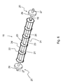
- the cutter roller 18 comprises a first, inner, continuous axle 19 (see Figure 6 ), which extends across the entire length of the cutter roll 18, and a second, outer, tubular axle 20, which is arranged concentrically on the inner axle 19 and is fixedly connected thereto.
- the cutter roll 18 further comprises first cutting elements in the form of six equally shaped circular knives 21, which are fixedly connected to the outer axle 20 and arranged concentrically thereto.
- the circular knives 21 are positioned at equal mutual distances along the length of the outer axle 20, where the outer circular knives are positioned at the ends of the outer axle 20.
- Each circular knife 21 has an edge 22, which extends in the circumferential direction around the periphery of the circular knife 21 so that the distance between the edge 22 and the outer axle 20 is constant.
- the edges 22 are wavy. Accordingly, the circular knives 21 define parallel, equidistant cutting planes, which are perpendicular to the axles 19 and 20.
- the cutter roller 18 also comprises second cutting elements in the form of two planar knife plates 23, which are fixedly connected to the outer axle 20 and extend in parallel to the axles 19, 20 between the outer circular knives.
- Each knife plate 23 projects in a radial direction from the envelope surface of the outer axle 20 and exhibits at its free, outer long side a straight edge 24, which is parallel to the axles 19 and 20 and thus perpendicular to the edges 22 of the circular knives 21.
- the edges 24 are wavy.
- the knife plates 23 project from the outer axle 20 in opposite directions, and thus have a mutual angular distance that is 180°.
- the protrusion of the knife plates 23 from the outer axle 20 is equal to the protrusion of the circular knives 21.
- the edges 24 of the knife plates 23 and the edges 22 of the circular knives 21 are arranged at the same distance from the outer axle 20. Accordingly, the edges 22 and 24 are arranged in the same cylindrical plane of the cutter roll 18.
- the outer axle 20 is centered on the inner axle 19, in the axle direction of the cutter roll 18, and has a length that is smaller than the inner axle 19. Consequently, the inner axle 19 comprises portions 25 which project from the outer axle 20 on each side thereof. In each such portion 25, the cutter roll 18 comprises a circular support roller 26, which is fixedly connected to the inner axle 19 and is arranged concentrically thereon.
- each support roller 26 preferably has a radius that is slightly smaller, preferably approx. 0.25-1.0 mm smaller, than the protrusion of the cutting elements 21, 23 from the rotational axis of the cutter roll 18, which in the present design example means that the diameter of the support rollers 26 is preferably approx. 0.5-2.0 mm smaller than the diameter of the circular knives 21.
- each support roller 26 preferably has a radius that is slightly larger than the protrusion of the cutting elements 21, 23 from the rotational axis of the cutter roll 18, wherein a smaller radius of the support rollers 26 produces shallower cuts or embossing patterns in the pasta dough than a larger radius.
- the support rollers 26 constitute positioning means for the knives 21, 23, in the sense that the radius of the support rollers 26 in relation to the protrusion of the cutting elements 21, 23 determines the depth of the cuts or patterns which the cutting elements 21, 23 produce in the pasta dough.
- the support rollers 26 constitute means for vertical positioning of the cutting elements 21, 23 when they are in the cutting position.
- the support rollers 26 are positioned at a predetermined distance, preferably approx. 2-10 cm, from the respective end of the inner axle 19. Accordingly, the inner axle 19 exhibits, at each end, portions 27 which extend beyond the support roller 26. These portions 27 are adapted to interact with said axle seats 17 of the traverser 8 and thus serve as the axle stubs of the cutter roll 18.
- the cutter roll 18 is entirely of stainless steel, with the exception of the support rollers 26, which preferably are of a polymer material, e.g. polyurethane, Teflon or other hard plastic.
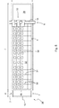
- the table surface 4 is cleared in that an operator moves the traverser 8 to a parking station 28 (see Figure 5 ), which is defined by the portion of the guides 7 that projects beyond the short side 6b of the table top 3, wherein the table surface 4 becomes freely accessible to the operator. Thereafter, the operator places the dough 29, which is to be cut up, on the table surface 4. This can be done in that the operator rolls out the dough directly onto the table surface 4 or, which is preferred, unrolls an already rolled-out dough onto the table surface 4. Thereby, the rolled-out dough forms a rolled-out, elongated, thin portion or sheet 29 on the table top 3. Thereafter, the operator moves the traverser 8 from the parking station 28, past the short side 6b, and in over the table surface 4.
- the operator brings the cutter roll 18 to its lower end position at this stage, i.e. the cutting position, so that the support rollers 26 of the cutter roll 18 are caused to interact with the table surface 4. If the cutter roll 18 is not vertically adjustable, the support rollers 26 get in contact with table surface 4 in connection with the traverser 8 being caused to pass the short side 6b.
- the circular knives 21 will be caused to interact with the table surface 4 when the cutter roll 18 is moved to the cutting position. If the cutting device 1 is set to make non-penetrating cuts in the pasta dough, there will be a small gap between the circular knives 21 and the table surface 4 when the cutter roll 18 is in the cutting position. In the following, it is assumed that the cutting device is set to make penetrating cuts in the pasta dough.
- the operator moves the traverser 8 across the sheet 29 laid out on the table surface 4 so that the cutter roll 18, as a result of frictional action between the support rollers 26 and the table surface 4, is caused to rotate around its axis.
- a certain friction is also obtained between the circular knives 21 and the table surface 4, but in the shown embodiment it is primarily the friction between the support rollers 26 and the table surface 4 that causes the cutter roll 18 to rotate or roll across the table surface 4.
- the circular knives 21 are caused to make continuous, longitudinal and, in this case, penetrating cuts 30 in the sheet 29, and the knife plates 23 are caused to alternately make transverse and penetrating cuts 31 therein. Accordingly, the first cutting elements, i.e.
- the circular knives 21, are adapted to make longitudinal cuts in the sheet 29, and the second cutting elements, i.e. the knife plates 23, are adapted to make transverse cuts.
- the edges 22 and 24 of the cutter roll 18 cut out a regular pattern in the sheet 29, comprising a plurality of rectangular figures or pieces 32, which recur regularly both in the transverse direction of the sheet 29 and in its longitudinal direction.
- the figures or pieces 32 are separated or parted after the cutting operation, since the cuts produced by the edges 22 and 24 of the cutter roll 18 are penetrating.
- the cutter roll 18 is caused to rotate at a peripheral speed, which is substantially the same as the speed at which the cutter roll 18 is moved across the table surface 4, i.e. at the translational speed of the cutter roll 18.
- the support rollers 26 also constitute rotating means, which cause the cutter roll 18 to rotate at a peripheral speed that substantially corresponds to the translational speed of the cutter roll 18 across the table surface 4. It has been found that a correspondance between peripheral speed and translational speed of the cutter roll gives a better cutting result than if the peripheral speed and the translational speed were to differ.
- the operator moves the traverser 8 manually along the guides 7.
- the cutting table 1 can comprise an operator-controlled motor (not shown) for propelling the traverser 8 along the guides 7.
- the traverser 8 comprises a dispensing device 33 for dispensing filling portions 34 onto the cut-out dough portions 32.
- the dispensing device 33 comprises three downwardly directed dispensing nozzles 35, each being connected to a container 36 for the filling.
- the nozzles 35 are arranged next to each other on one long side of the boom 15 and the containers 36 are arranged next to each other on the top side of the boom 15. The nozzles 35 are thus arranged next to each other in the transverse direction T of the table top 3.
- the nozzles 36 can be permanently positioned at predetermined positions along the longitudinal direction of the boom 15, but preferably each nozzle 36 is arranged on a carriage (not shown), running on a guide (not shown) along the boom 15, whereby the nozzle 36, either manually or motorizedly, can be placed at an optional position along the longitudinal direction of the boom 15.
- the process of dispensing the filling can be done manually in that the operator manually causes each nozzle 36 to dispense a filling portion 33 when the nozzle 36 is located above a cut-out dough portion 32.
- the cutting table 1 can comprise a steering and control device (not shown) which, while taking into consideration the shape of the cutter roll 18 and thus taking into consideration the shape of the cut-out pattern, automatically dispenses a filling portion 33 when the nozzle 36 passes above a cut-out dough portion 32.
- the steering and control device is preferably adapted to synchronize all movements, on the one hand, and the dispensing process, on the other hand, so that the correct amount of filling is placed in the correct position on the respective dough portion 32.
- the cutter roll 18 is detachably attached to the traverser 8 so that it easily can be replaced with cutter rolls of other shapes than the one shown in Figure 6 . It is appreciated that the number and shape of the knives of the cutter roll control the pattern that is cut out or embossed into the dough, and it is appreciated that other, alternative embodiments of cutter rolls are possible within the scope of the invention.
- FIG. 7 shows an alternative embodiment of a cutting means in the form of a cutter roll 38.
- the cutter roll 38 comprises a first axle portion 39 in the form of a rigid, circularly cylindrical and hollow cylinder body that exhibits, at its ends, end portions 40 which are substantially parallel with each other and substantially perpendicular to the cylinder body.
- the cutter roll 38 further comprises two second axle portions 41, which project from the respective end portion 40 of the first axle portion 39 and extend concentrically with the first axle portion 39.
- the first axle portion 39 and the second axle portions 41 are preferably of stainless steel, and are preferably joined together by welded joints.
- the cutter roll 38 further comprises a substantially tubular cutting body 42 of a polymer material, preferably a food-approved rubber with a hardness of about 80°Sh.
- the cutting body 42 is arranged concentrically on the first axle portion 39 and is fixedly connected to the envelope surface thereof.
- the cutting body 42 exhibits first cutting elements in the form of six equally shaped, concentric, length cutting knives 43, which form an integrated part of the cutting body 42 and project from the envelope surface of the cutting body 42.
- the knives 43 are arranged at equal mutual distances along the length of the cutting body 42, where the outer knives are positioned at the ends of the cutting body 42.
- Each knife 43 has an edge 44, which is preferably wavy and extends in the circumferential direction around the periphery of the cutting body 42 so that the distance between the edge 44 and the central axis of the cutter roll 38 is constant.
- the knives 43 have the shape of circular knives, defining parallel, equidistant cutting planes, which are perpendicular to the central axis of the cutter roll 38.
- the cutter roll 28 also comprises second cutting elements in the form of two cross cutting knives 45, which also form an integrated part of the cutting body 42 and project from the envelope surface of the cutting body 42.
- the knives 45 extend in parallel to the central axis of the cutter roll 38 along the entire length of the cutting body 42.
- Each knife 45 exhibits an edge 46, which extends in a substantially straight line parallel to the central axis of the cutter roll 38. Consequently, each edge 46 is substantially perpendicular to the edges 44 of the circular knives 43.
- the edges 46 are wavy.
- the knives 45 project from the envelope surface of the cutting body 42 in opposite directions and thus have a mutual angular distance that is 180°.
- the protrusion of the cross cutting knives 45 from the envelope surface of the cutting body 42 is equal to the protrusion of the circular knives 43.
- the edges 46 of the knives 45 and the edges 44 of the circular knives 43 are arranged at the same distance from the central axis of the cutter roll 38. Accordingly, the edges 44 and 46 are arranged in the same cylindrical plane of the cutter roll 38.
- the cutter roll 38 comprises a circular support roller 47, which is fixedly connected to the respective axle portion 41 and is arranged concentrically thereon.
- the support roller 47 has a radius that is slightly smaller, preferably approx. 0.25-1.0 mm smaller, than the radial protrusion of the edges 44 and 46 from the rotational centre of the cutter roll 38.
- the cutter roll 38 is thus adapted to make penetrating cuts in the sheet 29. It is appreciated, however, that the support rollers 47 can be designed with a radius that is larger than the radial protrusion of the edges 44, 46, in which case the cutter roll 38 is adapted to make non-penetrating cuts in the sheet 29.
- each axle portion 41 exhibits an end 48, which projects beyond the support roller 47.
- These axle ends 48 are adapted to interact with said axle seats 17 of the traverser 8 and thus serve as the stub axles of the cutter roll 38.
- the function of the cutter roll is the same as the one of the above-described cutter roll 18.
- the cutter roll 38 is caused to rotate around its axis by frictional action between the support rollers 47 and the table surface 4.
- a certain friction is also obtained between the circular knives 43 and the table surface 4, since also the circular knives 43 interact with the table surface 4 in this case, but it is primarily the friction between the support rollers 47 and the table surface 4 that causes the cutter roll 38 to rotate when it is moved across the table surface 4.
- the circular knives 43 are caused to make continuous, longitudinal and, in this case, penetrating cuts in the sheet 29 and the knife plates 45 are caused to alternately make transverse and penetrating cuts therein.
- the cutter roll 38 is caused to rotate at a peripheral speed, which is substantially the same as the speed at which the cutter roll 38 is moved across the table surface 4, i.e. at the translational speed of the cutter roll 38.
- the support rollers 47 also constitute rotating means, which cause the cutter roll 38 to rotate at a peripheral speed that substantially corresponds to the translational speed of the cutter roll 38 across the table surface 4.
- the cutting body 42 is cast in one piece, whereupon the cutting elements 43 and 45 are made by laser engraving the cast body. It is appreciated, however, that the cutting body can be manufactured in other ways.
- FIGS 8-10 illustrate how an edge of one of the knives of the cutting body 42 is deformed when the cutting body 42, in a penetrating cutting position, is moved across a dough portion 29 laid out on the table top 3 of the cutting device.
- penetrating cutting position means a position where the cutting body 42 is adapted to make penetrating cuts in the dough portion 29.
- Figure 8 shows in a cross section a section of the edge 49 before it has been brought in contact with the dough 29
- Figure 9 shows the edge section 49 in its lowermost position, when it is contact with the table top 3
- Figure 10 shows the edge section 49, when it is on its way up after having interacted with the dough 29.
- the edge section 49 is deformed in that it is compressed and expands in its transverse direction when it is brought in contact with the table top 3.
- the edge section 49 subsequently is lifted, it regains its original shape, whereas the dough 29, which is relatively plastic, retains the shape of the largest extension of the edge section 49. This sees to that the dough 29 easily releases from the edge section 49 and does not follow the edge section 49 in its return movement.
- the rotating means for causing the cutter roll to rotate at a peripheral speed can be realized in a variety of different ways.
- the rotation of the cutter roll can e.g. be driven by a motor, which is controlled so that the peripheral speed of the cutter roll corresponds to its translational speed. It is also possible to, purely manually, achieve a synchronization between peripheral speed and translational speed without utilizing friction against the table surface of the cutting device, e.g. through a suitable system of gear wheels and gear rims.
- cutting table 1 can be designed so that the table top 3 is adjustable in the vertical direction.
- said parking station 28 (see Figure 5 ) can be used for service and maintenance of the traverser 8.
- edges 22, 24, 44 and 46 not necessarily have to be wavy, but alternatively can be smooth, or have other, not shown designs.
- parts of the cutting table 1 can be made of a hard plastics material as, for example, polyurethane or Teflon, instead of a stainless material.
- the knives 21, 23, 43, 45 do not have to be arranged so that the cutting is done exactly in the longitudinal and transverse direction of the table top.
- the device can comprise cutting means which allow making of cuts in the sheet forming an angle in the interval 0°-90° with the longitudinal or transverse direction of the cutting table. It is further appreciated that these cuts do not necessarily have to be linear.
- the cutting device with a roll attached to the traverser for processing a plastically deformable body into a flat sheet with a predetermined thickness.
- a roll is placed in front of the cutting means, so that a rolling-out of the body can be done before the cutting.
- the envelope surface of the roll can be provided with a circumferential distance ring, which sees to that the same thickness is achieved across the entire length of the sheet.
- the envelope surface of the roll can either be smooth or patterned, depending on how the top side of the sheet should look after processing.
Landscapes
- Life Sciences & Earth Sciences (AREA)
- Engineering & Computer Science (AREA)
- Food Science & Technology (AREA)
- Forests & Forestry (AREA)
- Mechanical Engineering (AREA)
- Nutrition Science (AREA)
- Health & Medical Sciences (AREA)
- Chemical & Material Sciences (AREA)
- Polymers & Plastics (AREA)
- Treatment Of Fiber Materials (AREA)
- Manufacturing And Processing Devices For Dough (AREA)
- Noodles (AREA)
- Sawing (AREA)
- Milling Processes (AREA)
Claims (18)
- Schneidvorrichtung (1) zum Schneiden vorgegebener Formen (32) aus einem langgestreckten dünnen Abschnitt eines plastisch verformbaren Materials, dadurch gekennzeichnet, dass die Schneidvorrichtung (1) Folgendes umfasst:- eine feststehende Tischplatte (3), die eine ebenflächige Tischoberfläche (4) zum Tragen des langgestreckten Abschnitts (29) aufweist;- zwei langgestreckte Führungs- und Stützeinrichtungen (7), die auf jeder langen Seite (5a, 5b) der feststehenden Tischplatte (3) angeordnet sind;- eine Traverse (8), die in Längsrichtung (L) entlang der Führungs- und Stützeinrichtung (7) der Tischplatte (3) beweglich ist, und die sich quer zur Tischplatte (3) im Wesentlichen senkrecht zu der Längsrichtung (L) erstreckt und eine drehbare Schneidwalze (18, 38) umfasst, die sich über den Hauptteil der Breite (b) der Tischplatte (3) erstreckt, und Schneidelemente (21, 23, 43, 45) zum Schneiden der Formen (32) aus dem langgestreckten Abschnitt (29) umfasst, wobei die Traverse (8) so ausgebildet ist, dass sie entlang der Führungs- und Stützeinrichtung (7) mit der Schneidwalze (18, 38) in eine Schneidposition zum Ausschneiden der Formen (32) bewegt wird; und- eine Dreheinrichtung (26, 47) um zu bewirken, dass sich die Schneidwalze (18, 38) während der Bewegung der Schneidwalze (18, 38) in der Schneidposition mit einer Umfangsgeschwindigkeit dreht, die im Wesentlichen der Translationsgeschwindigkeit der Schneidwalze (18, 38) über die Tischoberfläche (4) entspricht.
- Schneidvorrichtung (1) nach Anspruch 1, dadurch gekennzeichnet, dass die Dreheinrichtung Stützrollen (26, 47) umfasst, die an den Enden der Schneidwalze (18, 38) angeordnet sind, um zu bewirken, dass sich die Schneidwalze (18, 38) durch Reibwirkung mit der Tischoberfläche (4) dreht, wenn sie in der Schneidposition über die Tischplatte (3) bewegt wird.
- Schneidvorrichtung (1) nach einem der Ansprüche 1 und 2, dadurch gekennzeichnet, dass die Schneidelemente erste Schneidelemente (21, 43), die so ausgebildet sind, dass sie im Wesentlichen längsgerichtete Schnitte in dem langgestreckten Abschnitt (29) ausführen, und zweite Schneidelemente (23, 45) umfassen, die so ausgebildet sind, dass sie im Wesentlichen quergerichtete Schnitte im langgestreckten Abschnitt (29) ausführen.
- Schneidvorrichtung (1) nach einem der Ansprüche 2 und 3, dadurch gekennzeichnet, dass die Schneidwalze (18) Folgendes umfasst:- eine erste Achse (19), die an ihren Enden Achszapfen (27) aufweist, die in Achssitzen (17) der Traverse (8) liegen;- eine zweite röhrenförmige Achse (20), die konzentrisch auf der ersten Achse (19) angeordnet ist,- eine Vielzahl gleich geformter Rundmesser (21), die jeweils eine Schneide (22) aufweisen, die sich in umlaufender Richtung um den Rand des Rundmessers (21) erstreckt, wobei die Rundmesser (21) konzentrisch auf der zweiten Achse (20) angeordnet sind, so dass sie parallele, abstandsgleiche Schnittebenen abgrenzen, die senkrecht zu den Achsen (19, 20) verlaufen, wobei die Rundmesser (21) erste Schneidelemente darstellen;- mindestens eine ebenflächige Messerplatte (23), die mit der zweiten Achse (20) verbunden ist und sich parallel zu den Achsen (19, 20) zwischen den äußeren der Rundmesser (21) erstreckt, wobei die mindestens eine Messerplatte (23) an einer freien langen Seite davon eine gerade Schneide (24) aufweist, die senkrecht zu den Schneiden (22) der Rundmesser (21) verläuft, wobei die mindestens eine Messerplatte (23) zweite Schneidelemente darstellt,
wobei die Schneiden (22, 24) auf der gleichen zylindrischen Ebene der Schneidwalze (18) angeordnet sind. - Schneidvorrichtung (1) nach Anspruch 4, dadurch gekennzeichnet, dass sie Stützrollen (26) umfasst, die fest mit der ersten Achse (19) verbunden und konzentrisch darauf angeordnet sind.
- Schneidvorrichtung (1) nach einem der Ansprüche 2 und 3, dadurch gekennzeichnet, dass die Schneidwalze (38) Folgendes umfasst:- einen ersten Achsenteil (39) in Form eines Zylinderkörpers, der an seinen Enden Endteile (40) aufweist,- zwei zweite Achsenteile (41), die aus dem jeweiligen Endteil (40) des ersten Achsenteils (39) hervorstehen und sich konzentrisch mit dem ersten Achsenteil (39) erstrecken; und- einen im Wesentlichen röhrenförmigen Schneidkörper (42) der konzentrisch auf dem ersten Achsenteil (39) angeordnet und fest mit dessen Hüllenoberfläche verbunden ist, wobei der Schneidkörper (42) Schneidelemente (43, 45) aufweist, die einen integrierten Bestandteil des Schneidkörpers (42) ausbilden und von der Hüllenoberfläche des Schneidkörpers (42) hervorstehen.
- Schneidvorrichtung (1) nach Anspruch 6, dadurch gekennzeichnet, dass sie Stützrollen (47) umfasst, die fest mit den zweiten Achsenteilen (41) verbunden und konzentrisch darauf angeordnet sind.
- Schneidvorrichtung (1) nach einem der Ansprüche 6 und 7, dadurch gekennzeichnet, dass der Schneidkörper (42) aus einem Polymermaterial besteht.
- Schneidvorrichtung (1) nach einem der vorhergehenden Ansprüche, dadurch gekennzeichnet, dass die Traverse (8) ein Stellglied (37) für die vertikale Bewegung des Schneidmittels (18, 38) zwischen einer oberen Endposition, in der das Schneidmittel (18, 38) nicht in Kontakt mit der Tischoberfläche (4) ist, und einer unteren Endposition umfasst, die die Schnittposition darstellt, in der die Schneidelemente (21, 23, 43, 45) in Kontakt mit der Tischoberfläche (4) sind.
- Schneidvorrichtung (1) nach einem der vorhergehenden Ansprüche, dadurch gekennzeichnet, dass die Traverse (8) eine Abgabevorrichtung (33) zum Abgeben von Füllungsportionen (34) auf die ausgeschnittenen Stücke (32) umfasst.
- Schneidvorrichtung (1) nach Anspruch 10, dadurch gekennzeichnet, dass die Dosiervorrichtung (33) eine Vielzahl von nach unten gerichteten Abgabedüsen (35) umfasst, die jeweils mit einem Behälter (36) zum Füllen verbunden sind, wobei die Abgabedüsen (35) nebeneinander in Querrichtung (T) zur Tischplatte (3) angeordnet sind.
- Schneidvorrichtung (1) nach Anspruch 11, dadurch gekennzeichnet, dass die Abgabedüsen (35) in der Traverse (8) dauerhaft in vorgegebenen Positionen angeordnet sind.
- Schneidvorrichtung (1) nach Anspruch 12, dadurch gekennzeichnet, dass jede Abgabedüse (35) auf einem Schlitten angeordnet ist, der so ausgebildet ist, dass er auf einer Führung der Traverse (8) läuft, wobei die Abgabedüse (35) entweder manuell oder motorisiert an einer optionalen Position entlang der Längsrichtung der Traverse (8) positionierbar ist.
- Schneidvorrichtung (1) nach einem der vorhergehenden Ansprüche, dadurch gekennzeichnet, dass sich die Führungs- und Stützeinrichtung (7) eine vorgegebene Strecke (s) außerhalb der kurzen Seite (6a) der Tischplatte (3) erstreckt, wobei der hervorstehende Teil der Führungs- und Stützeinrichtung (7) eine Parkstation (28) für die Traverse (8) abgrenzt, auf welcher Parkstation (28) die Traverse (8) positioniert werden kann, um die Tischoberfläche (4) frei zu machen.
- Schneidvorrichtung (1) nach einem der Ansprüche 1-14, dadurch gekennzeichnet, dass die Schneidvorrichtung (1) so ausgebildet ist, dass sie durchdringende Schnitte in dem langgestreckten Abschnitt (29) ausführt.
- Schneidvorrichtung (1) nach einem der Ansprüche 1-14, dadurch gekennzeichnet, dass die Schneidvorrichtung (1) so ausgebildet ist, dass sie nicht durchdringende Schnitte in dem langgestreckten Abschnitt (29) ausführt.
- Verfahren zum Schneiden vorgegebener Formen (32) aus einem langgestreckten dünnen Abschnitt (29) eines plastisch verformbaren Materials, wobei das Verfahren dadurch gekennzeichnet ist, dass es die folgenden Schritte umfasst:- dass der langgestreckte Abschnitt (29) auf einer festen ebenflächigen Tischoberfläche (4) einer Tischplatte (3) in einer Schneidvorrichtung (1) platziert oder ausgerollt wird; und- dass eine Traverse (8), die in der Schneidvorrichtung (1) beinhaltet ist und sich quer zur Tischplatte (3) erstreckt und eine Schneidwalze (18, 38) mit Schneidelementen (21, 23, 43, 45) umfasst, in eine Schneidposition über die langgestreckte Portion (29) bewegt wird, die auf der festen Tischplatte (3) ausgestreckt ist, wobei die Schneidwalze (18, 38) dazu veranlasst wird, sich mit einer Umfangsgeschwindigkeit zu drehen, die im Wesentlichen der Translationsgeschwindigkeit der Schneidwalze (18, 38) über die Tischplatte (3) entspricht, und wobei die Schneidelemente (21, 23, 43, 45) dazu veranlasst werden, dem langgestreckten Abschnitt (29) in die Formen (32) zu schneiden.
- Verwendung einer Schneidvorrichtung (1) nach einem der Ansprüche 1-16 zum Schneiden vorgegebener Formen (32) aus einem ausgerollten Speiseteig.
Applications Claiming Priority (2)
| Application Number | Priority Date | Filing Date | Title |
|---|---|---|---|
| SE0950415A SE533978C2 (sv) | 2009-06-05 | 2009-06-05 | Skäranordning och förfarande vid en sådan anordning |
| PCT/SE2010/050617 WO2010147536A1 (en) | 2009-06-05 | 2010-06-04 | Cutting device and method in such a device |
Publications (3)
| Publication Number | Publication Date |
|---|---|
| EP2437608A1 EP2437608A1 (de) | 2012-04-11 |
| EP2437608A4 EP2437608A4 (de) | 2014-04-09 |
| EP2437608B1 true EP2437608B1 (de) | 2015-08-19 |
Family
ID=43356611
Family Applications (1)
| Application Number | Title | Priority Date | Filing Date |
|---|---|---|---|
| EP10789814.0A Not-in-force EP2437608B1 (de) | 2009-06-05 | 2010-06-04 | Schneidevorrichtung und verfahren zur schneiden |
Country Status (9)
| Country | Link |
|---|---|
| US (1) | US20120079933A1 (de) |
| EP (1) | EP2437608B1 (de) |
| JP (1) | JP5469242B2 (de) |
| CN (1) | CN102802423B (de) |
| CA (1) | CA2763731C (de) |
| MX (1) | MX2011012734A (de) |
| RU (1) | RU2533027C2 (de) |
| SE (1) | SE533978C2 (de) |
| WO (1) | WO2010147536A1 (de) |
Families Citing this family (23)
| Publication number | Priority date | Publication date | Assignee | Title |
|---|---|---|---|---|
| CN104255846B (zh) * | 2014-09-02 | 2016-03-16 | 余姚市庆达机械有限公司 | 一种切料机 |
| CN104842384A (zh) * | 2014-11-11 | 2015-08-19 | 重庆市九龙坡区仔仔食品厂 | 便捷回收及加料的牛板筋切片及切丝机构 |
| CN104858909A (zh) * | 2014-11-11 | 2015-08-26 | 重庆市九龙坡区仔仔食品厂 | 带回收及加料的牛板筋切片及切丝机构 |
| CN105128051B (zh) * | 2015-08-21 | 2016-11-30 | 福建省速卖通电子商务有限公司 | 一种智能切菜装置 |
| CN105171796A (zh) * | 2015-09-25 | 2015-12-23 | 江门市金钩包装机械有限公司 | 一种瓦楞纸分切装置 |
| AT517684B1 (de) * | 2015-12-04 | 2017-04-15 | König Maschinen Ges M B H | Teig-Längsschneide und/oder -Prägeeinrichtung |
| CN108338193B (zh) * | 2017-01-22 | 2023-04-21 | 北京申晨机械设备有限公司 | 一种面片生产装置及泡芙生产设备 |
| CN107318915A (zh) * | 2017-06-12 | 2017-11-07 | 尚宝泰机械科技(昆山)有限公司 | 一种面条分割设备 |
| CN109129635A (zh) * | 2017-06-27 | 2019-01-04 | 深圳市玲涛光电科技有限公司 | 背光源切割装置以及背光源切割方法 |
| CN107351155B (zh) * | 2017-08-29 | 2023-12-22 | 重庆市铬帅服饰贸易有限公司 | 一种新型砂纸切块机 |
| CN108514019A (zh) * | 2018-06-06 | 2018-09-11 | 宁德市海扬食品有限公司 | 一种鱿鱼花加工设备 |
| FI3809854T3 (fi) | 2018-06-27 | 2023-04-21 | Gen Mills Inc | Kova taco-kuori sekä kovan taco-kuoren valmistusmenetelmä ja -laitteisto |
| US10721938B2 (en) * | 2018-06-27 | 2020-07-28 | General Mills, Inc. | Hard taco shell and method and apparatus for producing the hard taco shell |
| RU190125U1 (ru) * | 2019-04-12 | 2019-06-19 | Закрытое акционерное общество Булочно-кондитерский комбинат "Коломенский" | Устройство для нанесения надрезов на тестовую заготовку |
| EP3732972B1 (de) * | 2019-04-30 | 2023-10-25 | Tonelli, Dante | Einheit zur formung von kurzen nudeln |
| CN113043346B (zh) * | 2019-12-23 | 2022-12-13 | 四川亘峰科技有限公司 | 级进切料装置 |
| CN111136704B (zh) * | 2020-01-08 | 2021-08-03 | 安徽旺德福食品有限公司 | 一种用于加工魔芋素毛肚的专用生产装置 |
| EP3994996B1 (de) * | 2020-11-10 | 2025-08-20 | Radie B.V. | Vorrichtung zum schneiden eines teigbandes auf einem substrat, insbesondere einem förderer |
| CN112841240B (zh) * | 2021-01-18 | 2023-05-05 | 艾斯普瑞(广州)食品有限公司 | 一种抹茶面条成型设备 |
| CN113400377B (zh) * | 2021-06-08 | 2022-11-15 | 中科科正自动化工程有限公司 | 一种米粉切割机 |
| CN114274192B (zh) * | 2021-11-17 | 2024-03-08 | 盒马(中国)有限公司 | 一种切割装置及方法 |
| CN115039800B (zh) * | 2022-06-29 | 2025-07-25 | 思念食品(河南)有限公司 | 一体式馄饨制作自动化生产线 |
| KR102850816B1 (ko) * | 2022-11-14 | 2025-08-26 | 주식회사 신행이엔티 | 쌀가루 김치과자 제조장치 |
Family Cites Families (42)
| Publication number | Priority date | Publication date | Assignee | Title |
|---|---|---|---|---|
| US7482A (en) * | 1850-07-02 | Improvement in machines for cutting lozenges | ||
| US78300A (en) * | 1868-05-26 | Improved apparatus for rolling dough | ||
| US127235A (en) * | 1872-05-28 | Reuben w | ||
| DE232509C (de) | ||||
| US353177A (en) * | 1886-11-23 | Rolling-pin | ||
| GB191001412A (en) * | 1910-01-19 | 1910-11-24 | Peek Frean & Company Ltd | Improvements in the Manufacture of Biscuits and in Biscuit Cutting Machines. |
| US1357665A (en) * | 1920-05-28 | 1920-11-02 | Wrigley William Jun Co | Gum sheeting and scoring machine |
| US1479925A (en) * | 1923-05-15 | 1924-01-08 | Oleri Rosa | Cylindrical ravioli shaper, sealer, and cutter |
| US1556887A (en) * | 1924-08-30 | 1925-10-13 | Winters May | Dough-rolling machine |
| US1807009A (en) * | 1930-06-07 | 1931-05-26 | Pinnelli Donato | Convertible implement |
| GB581852A (en) * | 1944-05-18 | 1946-10-28 | Antonio Monaco | Improvements in machines for cutting continuously moving pastry strips or the like |
| US2437202A (en) | 1945-02-28 | 1948-03-02 | Marino Salvatore | Ravioli machine |
| CH314903A (de) * | 1953-07-17 | 1956-07-15 | Krebs Charles | Gebäckformmaschine |
| US3186362A (en) * | 1963-03-25 | 1965-06-01 | Sr Daniel A Iannuzzi | Rapid ravioli maker |
| US3299835A (en) * | 1964-04-10 | 1967-01-24 | Marsili Domenick | Ravioli making apparatus |
| US3364877A (en) * | 1964-12-14 | 1968-01-23 | Zublena Vittorio | Houshold machine for making raviolis |
| US3753638A (en) * | 1971-05-18 | 1973-08-21 | N Simpson | Apparatus for sheeting dough |
| JPS5119675Y2 (de) * | 1974-03-25 | 1976-05-24 | ||
| US3880030A (en) * | 1974-07-01 | 1975-04-29 | Nabisco Inc | Rotary cutter assembly |
| JPS523433Y2 (de) * | 1974-07-27 | 1977-01-25 | ||
| JPS5130197U (de) * | 1974-08-20 | 1976-03-04 | ||
| US4193272A (en) * | 1974-11-22 | 1980-03-18 | Bernard Vincent E | Portion controlled frozen food |
| US3994652A (en) * | 1975-05-12 | 1976-11-30 | Peter Kuzyk | Combined rolling pin and dough cutter |
| FR2460761A1 (fr) * | 1979-07-06 | 1981-01-30 | Woock Jean Pierre | Guide pour outil a rainurer |
| US4266923A (en) * | 1980-02-21 | 1981-05-12 | Curnes John J | Means of support for the rollers of a press |
| US4521174A (en) * | 1982-09-17 | 1985-06-04 | Murray Kornhauser | Adjustable dough manipulator |
| US4718769A (en) * | 1986-09-12 | 1988-01-12 | Domino's Pizza, Inc. | Dough preparation apparatus |
| DE3903746C1 (de) * | 1989-02-09 | 1990-05-31 | A. Fritsch Gmbh & Co Kg, 8711 Markt Einersheim, De | |
| JPH0811390B2 (ja) * | 1989-04-14 | 1996-02-07 | 株式会社川上製作所 | 積層シートの裁断装置 |
| DE3924053A1 (de) * | 1989-07-21 | 1991-01-24 | Wilhelm Aichele | Vorrichtung zum rotationsschneiden von werkstoffbahnen |
| JPH0795910B2 (ja) * | 1989-07-28 | 1995-10-18 | レオン自動機株式会社 | 生地延展方法及び装置 |
| IT1242385B (it) * | 1990-03-14 | 1994-03-04 | Parmigiana Spa | Macchina raviolatrice |
| JPH0771442B2 (ja) * | 1990-07-13 | 1995-08-02 | レオン自動機株式会社 | パン生地の連続切断方法及び装置 |
| US5162119A (en) * | 1991-04-09 | 1992-11-10 | Nabisco, Inc. | Printing and forming apparatus for making printed baked goods |
| US5514397A (en) * | 1992-04-02 | 1996-05-07 | Holy Ravioli Pasta Company | Process for making a layered dough sheet product |
| US5546850A (en) * | 1995-07-06 | 1996-08-20 | Zaveri; Vikram H. | Electric rolling pin apparatus for making discs of dough |
| NL1002456C2 (nl) * | 1996-02-27 | 1997-06-12 | Nasier Ahmad Yusufi | Werkwijze voor het vervaardigen van brood uit brooddeeg; alsmede snij-orgaan voor gebruik daarbij. |
| US7156007B1 (en) * | 1996-05-20 | 2007-01-02 | Stockhausen Gmbh | Device and a process for coarsely grinding hydrous polymer gels |
| USD402858S (en) * | 1997-10-31 | 1998-12-22 | Iannuzzi Deceased Daniel Andrew | Combined ravioli roller and cover therefor |
| CH693743A5 (de) * | 2000-03-10 | 2004-01-15 | Martin J Rotter | Schneidvorrichtung zum Schneiden von Profilen in luftdurchlossigen und elastischen Materialien und Verfahren hierfur. |
| US7854696B2 (en) * | 2006-01-11 | 2010-12-21 | Lifetime Brands, Inc. | Rolling pin with adjustable offset |
| DE102007001384A1 (de) * | 2006-03-09 | 2007-09-13 | Pcm Krause Gmbh | Vorrichtung zum Schneiden und Separieren von Teiglingen in beliebige geometrische Formen aus einem kontinuierlich oder getaktet geführten Teigband |
-
2009
- 2009-06-05 SE SE0950415A patent/SE533978C2/sv not_active IP Right Cessation
-
2010
- 2010-06-04 MX MX2011012734A patent/MX2011012734A/es not_active Application Discontinuation
- 2010-06-04 RU RU2011148008/13A patent/RU2533027C2/ru not_active IP Right Cessation
- 2010-06-04 CN CN201080024795.XA patent/CN102802423B/zh not_active Expired - Fee Related
- 2010-06-04 WO PCT/SE2010/050617 patent/WO2010147536A1/en not_active Ceased
- 2010-06-04 EP EP10789814.0A patent/EP2437608B1/de not_active Not-in-force
- 2010-06-04 US US13/376,263 patent/US20120079933A1/en not_active Abandoned
- 2010-06-04 JP JP2012513905A patent/JP5469242B2/ja not_active Expired - Fee Related
- 2010-06-04 CA CA 2763731 patent/CA2763731C/en not_active Expired - Fee Related
Also Published As
| Publication number | Publication date |
|---|---|
| CN102802423B (zh) | 2015-10-07 |
| RU2533027C2 (ru) | 2014-11-20 |
| CA2763731A1 (en) | 2010-12-23 |
| JP5469242B2 (ja) | 2014-04-16 |
| EP2437608A4 (de) | 2014-04-09 |
| EP2437608A1 (de) | 2012-04-11 |
| RU2011148008A (ru) | 2013-07-20 |
| WO2010147536A1 (en) | 2010-12-23 |
| SE533978C2 (sv) | 2011-03-15 |
| MX2011012734A (es) | 2011-12-16 |
| HK1178746A1 (en) | 2013-09-19 |
| CN102802423A (zh) | 2012-11-28 |
| JP2012528590A (ja) | 2012-11-15 |
| US20120079933A1 (en) | 2012-04-05 |
| SE0950415A1 (sv) | 2010-12-06 |
| CA2763731C (en) | 2013-09-03 |
Similar Documents
| Publication | Publication Date | Title |
|---|---|---|
| CA2763731C (en) | Cutting device with correlated rotation and translation speeds | |
| US6763750B2 (en) | Conveyor system for slicer apparatus | |
| US20110177190A1 (en) | Blunt edge dough cutter | |
| CA2043452C (en) | Forming of dough based product | |
| JP2000512509A (ja) | 連続的な生地搬送路から個々の生地片を製造するための方法および装置ならびに押抜型 | |
| CN101218044A (zh) | 滚轧成形机及滚轧成形方法 | |
| EP1099379B1 (de) | Vorrichtung zum Formen von Brotteigstücken oder dergleichen | |
| EP1192863A2 (de) | Vorrichtung für die automatische Drehung von Teigwaren während deren Herstellung | |
| CA2440525C (en) | A structure and method for cutting slabs of natural cheeses into shape(s) via cutting blades of a pattern such that the shape(s) are tessellated or nested | |
| HK1178746B (en) | Cutting device and method in such a device | |
| US6364653B1 (en) | Edge rolling device for dough pieces | |
| US4179959A (en) | Method and apparatus for the cutting of split tiles | |
| EP0377964A1 (de) | Verfahren und Vorrichtung zur Behandlung von Teig | |
| EP4442415B1 (de) | Vorrichtung zum schneiden oder stanzen von teig | |
| CN211591533U (zh) | 片材定位压花装置 | |
| WO2021247510A1 (en) | Cutting apparatus for dough products | |
| DE4340985A1 (de) | Verfahren und Vorrichtung zum Herstellen von Faltverpackungen aus einseitiger Wellpappe | |
| CN118140958B (zh) | 一种乌冬面生产装置及生产工艺 | |
| CN211591532U (zh) | 片材定位压花微调装置 | |
| CA2262113C (en) | Edge rolling device for dough pieces | |
| FI60487B (fi) | Kontinuerligt foerfarande foer framstaellning av fyllda bageriprodukter | |
| HRP20241169T1 (hr) | Uređaj i postupak za oblikovanje punjenih tjestenina od lista tijesta | |
| CN117416126A (zh) | 3d面料生产设备及工艺 | |
| DE77723C (de) | Verfahren und Maschine zur Ausgestaltung der Oberflächen von geblasenen Hohlglaskörpern | |
| TWM306169U (en) | Thin-sheet cutting machine for foaming product |
Legal Events
| Date | Code | Title | Description |
|---|---|---|---|
| PUAI | Public reference made under article 153(3) epc to a published international application that has entered the european phase |
Free format text: ORIGINAL CODE: 0009012 |
|
| 17P | Request for examination filed |
Effective date: 20111223 |
|
| AK | Designated contracting states |
Kind code of ref document: A1 Designated state(s): AL AT BE BG CH CY CZ DE DK EE ES FI FR GB GR HR HU IE IS IT LI LT LU LV MC MK MT NL NO PL PT RO SE SI SK SM TR |
|
| DAX | Request for extension of the european patent (deleted) | ||
| RIC1 | Information provided on ipc code assigned before grant |
Ipc: B26D 1/00 20060101ALI20140226BHEP Ipc: A21C 5/00 20060101ALI20140226BHEP Ipc: A23L 1/16 20060101ALI20140226BHEP Ipc: A21C 11/12 20060101AFI20140226BHEP |
|
| A4 | Supplementary search report drawn up and despatched |
Effective date: 20140312 |
|
| 17Q | First examination report despatched |
Effective date: 20140328 |
|
| GRAP | Despatch of communication of intention to grant a patent |
Free format text: ORIGINAL CODE: EPIDOSNIGR1 |
|
| INTG | Intention to grant announced |
Effective date: 20141128 |
|
| GRAP | Despatch of communication of intention to grant a patent |
Free format text: ORIGINAL CODE: EPIDOSNIGR1 |
|
| INTG | Intention to grant announced |
Effective date: 20150319 |
|
| GRAS | Grant fee paid |
Free format text: ORIGINAL CODE: EPIDOSNIGR3 |
|
| GRAA | (expected) grant |
Free format text: ORIGINAL CODE: 0009210 |
|
| AK | Designated contracting states |
Kind code of ref document: B1 Designated state(s): AL AT BE BG CH CY CZ DE DK EE ES FI FR GB GR HR HU IE IS IT LI LT LU LV MC MK MT NL NO PL PT RO SE SI SK SM TR |
|
| REG | Reference to a national code |
Ref country code: GB Ref legal event code: FG4D |
|
| REG | Reference to a national code |
Ref country code: CH Ref legal event code: EP |
|
| REG | Reference to a national code |
Ref country code: IE Ref legal event code: FG4D |
|
| REG | Reference to a national code |
Ref country code: AT Ref legal event code: REF Ref document number: 743135 Country of ref document: AT Kind code of ref document: T Effective date: 20150915 |
|
| REG | Reference to a national code |
Ref country code: DE Ref legal event code: R096 Ref document number: 602010026864 Country of ref document: DE |
|
| REG | Reference to a national code |
Ref country code: SE Ref legal event code: TRGR |
|
| REG | Reference to a national code |
Ref country code: NL Ref legal event code: FP |
|
| REG | Reference to a national code |
Ref country code: AT Ref legal event code: MK05 Ref document number: 743135 Country of ref document: AT Kind code of ref document: T Effective date: 20150819 |
|
| REG | Reference to a national code |
Ref country code: LT Ref legal event code: MG4D |
|
| PG25 | Lapsed in a contracting state [announced via postgrant information from national office to epo] |
Ref country code: FI Free format text: LAPSE BECAUSE OF FAILURE TO SUBMIT A TRANSLATION OF THE DESCRIPTION OR TO PAY THE FEE WITHIN THE PRESCRIBED TIME-LIMIT Effective date: 20150819 Ref country code: GR Free format text: LAPSE BECAUSE OF FAILURE TO SUBMIT A TRANSLATION OF THE DESCRIPTION OR TO PAY THE FEE WITHIN THE PRESCRIBED TIME-LIMIT Effective date: 20151120 Ref country code: NO Free format text: LAPSE BECAUSE OF FAILURE TO SUBMIT A TRANSLATION OF THE DESCRIPTION OR TO PAY THE FEE WITHIN THE PRESCRIBED TIME-LIMIT Effective date: 20151119 Ref country code: LT Free format text: LAPSE BECAUSE OF FAILURE TO SUBMIT A TRANSLATION OF THE DESCRIPTION OR TO PAY THE FEE WITHIN THE PRESCRIBED TIME-LIMIT Effective date: 20150819 Ref country code: LV Free format text: LAPSE BECAUSE OF FAILURE TO SUBMIT A TRANSLATION OF THE DESCRIPTION OR TO PAY THE FEE WITHIN THE PRESCRIBED TIME-LIMIT Effective date: 20150819 |
|
| PG25 | Lapsed in a contracting state [announced via postgrant information from national office to epo] |
Ref country code: ES Free format text: LAPSE BECAUSE OF FAILURE TO SUBMIT A TRANSLATION OF THE DESCRIPTION OR TO PAY THE FEE WITHIN THE PRESCRIBED TIME-LIMIT Effective date: 20150819 Ref country code: PL Free format text: LAPSE BECAUSE OF FAILURE TO SUBMIT A TRANSLATION OF THE DESCRIPTION OR TO PAY THE FEE WITHIN THE PRESCRIBED TIME-LIMIT Effective date: 20150819 Ref country code: AT Free format text: LAPSE BECAUSE OF FAILURE TO SUBMIT A TRANSLATION OF THE DESCRIPTION OR TO PAY THE FEE WITHIN THE PRESCRIBED TIME-LIMIT Effective date: 20150819 Ref country code: IS Free format text: LAPSE BECAUSE OF FAILURE TO SUBMIT A TRANSLATION OF THE DESCRIPTION OR TO PAY THE FEE WITHIN THE PRESCRIBED TIME-LIMIT Effective date: 20151219 Ref country code: PT Free format text: LAPSE BECAUSE OF FAILURE TO SUBMIT A TRANSLATION OF THE DESCRIPTION OR TO PAY THE FEE WITHIN THE PRESCRIBED TIME-LIMIT Effective date: 20151221 |
|
| PG25 | Lapsed in a contracting state [announced via postgrant information from national office to epo] |
Ref country code: SK Free format text: LAPSE BECAUSE OF FAILURE TO SUBMIT A TRANSLATION OF THE DESCRIPTION OR TO PAY THE FEE WITHIN THE PRESCRIBED TIME-LIMIT Effective date: 20150819 Ref country code: EE Free format text: LAPSE BECAUSE OF FAILURE TO SUBMIT A TRANSLATION OF THE DESCRIPTION OR TO PAY THE FEE WITHIN THE PRESCRIBED TIME-LIMIT Effective date: 20150819 Ref country code: DK Free format text: LAPSE BECAUSE OF FAILURE TO SUBMIT A TRANSLATION OF THE DESCRIPTION OR TO PAY THE FEE WITHIN THE PRESCRIBED TIME-LIMIT Effective date: 20150819 Ref country code: CZ Free format text: LAPSE BECAUSE OF FAILURE TO SUBMIT A TRANSLATION OF THE DESCRIPTION OR TO PAY THE FEE WITHIN THE PRESCRIBED TIME-LIMIT Effective date: 20150819 |
|
| REG | Reference to a national code |
Ref country code: DE Ref legal event code: R097 Ref document number: 602010026864 Country of ref document: DE |
|
| PG25 | Lapsed in a contracting state [announced via postgrant information from national office to epo] |
Ref country code: RO Free format text: LAPSE BECAUSE OF FAILURE TO SUBMIT A TRANSLATION OF THE DESCRIPTION OR TO PAY THE FEE WITHIN THE PRESCRIBED TIME-LIMIT Effective date: 20150819 |
|
| PLBE | No opposition filed within time limit |
Free format text: ORIGINAL CODE: 0009261 |
|
| STAA | Information on the status of an ep patent application or granted ep patent |
Free format text: STATUS: NO OPPOSITION FILED WITHIN TIME LIMIT |
|
| 26N | No opposition filed |
Effective date: 20160520 |
|
| PG25 | Lapsed in a contracting state [announced via postgrant information from national office to epo] |
Ref country code: SI Free format text: LAPSE BECAUSE OF FAILURE TO SUBMIT A TRANSLATION OF THE DESCRIPTION OR TO PAY THE FEE WITHIN THE PRESCRIBED TIME-LIMIT Effective date: 20150819 |
|
| PGFP | Annual fee paid to national office [announced via postgrant information from national office to epo] |
Ref country code: GB Payment date: 20160930 Year of fee payment: 7 |
|
| PG25 | Lapsed in a contracting state [announced via postgrant information from national office to epo] |
Ref country code: BE Free format text: LAPSE BECAUSE OF FAILURE TO SUBMIT A TRANSLATION OF THE DESCRIPTION OR TO PAY THE FEE WITHIN THE PRESCRIBED TIME-LIMIT Effective date: 20150819 |
|
| REG | Reference to a national code |
Ref country code: DE Ref legal event code: R119 Ref document number: 602010026864 Country of ref document: DE |
|
| PG25 | Lapsed in a contracting state [announced via postgrant information from national office to epo] |
Ref country code: MC Free format text: LAPSE BECAUSE OF FAILURE TO SUBMIT A TRANSLATION OF THE DESCRIPTION OR TO PAY THE FEE WITHIN THE PRESCRIBED TIME-LIMIT Effective date: 20150819 |
|
| REG | Reference to a national code |
Ref country code: SE Ref legal event code: EUG Ref country code: CH Ref legal event code: PL |
|
| REG | Reference to a national code |
Ref country code: NL Ref legal event code: MM Effective date: 20160701 |
|
| PG25 | Lapsed in a contracting state [announced via postgrant information from national office to epo] |
Ref country code: SE Free format text: LAPSE BECAUSE OF NON-PAYMENT OF DUE FEES Effective date: 20160605 |
|
| REG | Reference to a national code |
Ref country code: IE Ref legal event code: MM4A |
|
| REG | Reference to a national code |
Ref country code: FR Ref legal event code: ST Effective date: 20170228 |
|
| PG25 | Lapsed in a contracting state [announced via postgrant information from national office to epo] |
Ref country code: CH Free format text: LAPSE BECAUSE OF NON-PAYMENT OF DUE FEES Effective date: 20160630 Ref country code: DE Free format text: LAPSE BECAUSE OF NON-PAYMENT OF DUE FEES Effective date: 20170103 Ref country code: FR Free format text: LAPSE BECAUSE OF NON-PAYMENT OF DUE FEES Effective date: 20160630 Ref country code: LI Free format text: LAPSE BECAUSE OF NON-PAYMENT OF DUE FEES Effective date: 20160630 |
|
| PG25 | Lapsed in a contracting state [announced via postgrant information from national office to epo] |
Ref country code: NL Free format text: LAPSE BECAUSE OF NON-PAYMENT OF DUE FEES Effective date: 20160701 Ref country code: IE Free format text: LAPSE BECAUSE OF NON-PAYMENT OF DUE FEES Effective date: 20160604 |
|
| PG25 | Lapsed in a contracting state [announced via postgrant information from national office to epo] |
Ref country code: IT Free format text: LAPSE BECAUSE OF NON-PAYMENT OF DUE FEES Effective date: 20160604 |
|
| GBPC | Gb: european patent ceased through non-payment of renewal fee |
Effective date: 20170604 |
|
| PG25 | Lapsed in a contracting state [announced via postgrant information from national office to epo] |
Ref country code: GB Free format text: LAPSE BECAUSE OF NON-PAYMENT OF DUE FEES Effective date: 20170604 |
|
| PG25 | Lapsed in a contracting state [announced via postgrant information from national office to epo] |
Ref country code: CY Free format text: LAPSE BECAUSE OF FAILURE TO SUBMIT A TRANSLATION OF THE DESCRIPTION OR TO PAY THE FEE WITHIN THE PRESCRIBED TIME-LIMIT Effective date: 20150819 Ref country code: SM Free format text: LAPSE BECAUSE OF FAILURE TO SUBMIT A TRANSLATION OF THE DESCRIPTION OR TO PAY THE FEE WITHIN THE PRESCRIBED TIME-LIMIT Effective date: 20150819 Ref country code: HU Free format text: LAPSE BECAUSE OF FAILURE TO SUBMIT A TRANSLATION OF THE DESCRIPTION OR TO PAY THE FEE WITHIN THE PRESCRIBED TIME-LIMIT; INVALID AB INITIO Effective date: 20100604 |
|
| PG25 | Lapsed in a contracting state [announced via postgrant information from national office to epo] |
Ref country code: LU Free format text: LAPSE BECAUSE OF NON-PAYMENT OF DUE FEES Effective date: 20160604 Ref country code: MK Free format text: LAPSE BECAUSE OF FAILURE TO SUBMIT A TRANSLATION OF THE DESCRIPTION OR TO PAY THE FEE WITHIN THE PRESCRIBED TIME-LIMIT Effective date: 20150819 Ref country code: HR Free format text: LAPSE BECAUSE OF FAILURE TO SUBMIT A TRANSLATION OF THE DESCRIPTION OR TO PAY THE FEE WITHIN THE PRESCRIBED TIME-LIMIT Effective date: 20150819 Ref country code: MT Free format text: LAPSE BECAUSE OF NON-PAYMENT OF DUE FEES Effective date: 20160630 Ref country code: TR Free format text: LAPSE BECAUSE OF FAILURE TO SUBMIT A TRANSLATION OF THE DESCRIPTION OR TO PAY THE FEE WITHIN THE PRESCRIBED TIME-LIMIT Effective date: 20150819 |
|
| PG25 | Lapsed in a contracting state [announced via postgrant information from national office to epo] |
Ref country code: BG Free format text: LAPSE BECAUSE OF FAILURE TO SUBMIT A TRANSLATION OF THE DESCRIPTION OR TO PAY THE FEE WITHIN THE PRESCRIBED TIME-LIMIT Effective date: 20150819 |
|
| PG25 | Lapsed in a contracting state [announced via postgrant information from national office to epo] |
Ref country code: AL Free format text: LAPSE BECAUSE OF FAILURE TO SUBMIT A TRANSLATION OF THE DESCRIPTION OR TO PAY THE FEE WITHIN THE PRESCRIBED TIME-LIMIT Effective date: 20150819 |