EP2435218B1 - Pivoting arrangement - Google Patents
Pivoting arrangement Download PDFInfo
- Publication number
- EP2435218B1 EP2435218B1 EP10727900.2A EP10727900A EP2435218B1 EP 2435218 B1 EP2435218 B1 EP 2435218B1 EP 10727900 A EP10727900 A EP 10727900A EP 2435218 B1 EP2435218 B1 EP 2435218B1
- Authority
- EP
- European Patent Office
- Prior art keywords
- pivoting
- pivoting member
- spring
- arrangement
- resting position
- Prior art date
- Legal status (The legal status is an assumption and is not a legal conclusion. Google has not performed a legal analysis and makes no representation as to the accuracy of the status listed.)
- Active
Links
Images


Classifications
-
- B—PERFORMING OPERATIONS; TRANSPORTING
- B26—HAND CUTTING TOOLS; CUTTING; SEVERING
- B26B—HAND-HELD CUTTING TOOLS NOT OTHERWISE PROVIDED FOR
- B26B19/00—Clippers or shavers operating with a plurality of cutting edges, e.g. hair clippers, dry shavers
- B26B19/02—Clippers or shavers operating with a plurality of cutting edges, e.g. hair clippers, dry shavers of the reciprocating-cutter type
- B26B19/04—Cutting heads therefor; Cutters therefor; Securing equipment thereof
- B26B19/044—Manufacture and assembly of cutter blocks
-
- B—PERFORMING OPERATIONS; TRANSPORTING
- B26—HAND CUTTING TOOLS; CUTTING; SEVERING
- B26B—HAND-HELD CUTTING TOOLS NOT OTHERWISE PROVIDED FOR
- B26B19/00—Clippers or shavers operating with a plurality of cutting edges, e.g. hair clippers, dry shavers
- B26B19/02—Clippers or shavers operating with a plurality of cutting edges, e.g. hair clippers, dry shavers of the reciprocating-cutter type
- B26B19/04—Cutting heads therefor; Cutters therefor; Securing equipment thereof
- B26B19/048—Complete cutting head being movable
-
- B—PERFORMING OPERATIONS; TRANSPORTING
- B26—HAND CUTTING TOOLS; CUTTING; SEVERING
- B26B—HAND-HELD CUTTING TOOLS NOT OTHERWISE PROVIDED FOR
- B26B19/00—Clippers or shavers operating with a plurality of cutting edges, e.g. hair clippers, dry shavers
- B26B19/38—Details of, or accessories for, hair clippers, or dry shavers, e.g. housings, casings, grips, guards
- B26B19/3806—Accessories
Definitions
- the present invention relates to a pivoting arrangement for a device having a contour following function such as e.g. a shaving device.
- Conventional shaving and grooming devices are sometimes equipped with a pivoting arrangement providing a contour following function. Contour following functions are known from other devices as well such as epilators, skin rejuvenation, wrinkle treatment and trimming devices.
- a moving part of the shaving head is spring loaded towards an extreme angular position, so that it assumes this extreme position when it is not submitted to any external forces.
- a moving part of the shaving head is arranged to assume a predefined resting position, e.g. a middle position, when it is not submitted to any external forces.
- This resting position can be spring loaded.
- FIG. 1 Such a conventional middle position pivoting arrangement is known from US 6,301,786 , and is schematically shown in figure 1 .
- a pivoting member 1 is supported by a supporting member or cradle 2, allowing it to pivot around an axis A.
- Two (or more) spring members 3 are arranged at the base plate 4 of the supporting member or cradle 2.
- both spring members 3 are preloaded against the pivoting member 1.
- the pivoting member When the pivoting member is forced out of its resting position, it will depress one of the springs further, while extending the other spring. The force of the depressed spring will now become greater than the force from the extended spring, thus offsetting the equilibrium of the springs, and creating a net force acting on the pivoting member towards the middle position.
- a potential problem with such conventional pivoting arrangements is that if the two springs have, or grow to have, slightly different spring constants, the equilibrium of the springs may become permanently offset, so that the pivoting member will fail to resume its middle position after being depressed. As a result, the resting position of the pivoting member will no longer be the middle position, but a slightly angled position.
- a pivoting arrangement for a device having a contour following function such as e.g. a shaving device, comprising a pivoting member, adapted to support a shaving head, a cradle, pivotally supporting the pivoting member, and a spring loading arrangement comprising at least one deformable spring element, and arranged to interact with the pivoting member in a first point of action to exert a force acting to move the pivoting member in a first pivoting direction, and in a second point of action to exert a force acting to move the pivoting member in a second pivoting direction, the spring loading arrangement thereby biasing the pivoting member in a resting position.
- the spring loading arrangement further has a limited active range, so that, when the pivoting member is brought out of the resting position in the first pivoting direction, the spring loading arrangement is prevented from interacting with the pivoting member in the first point of action, and when the pivoting member is brought out of the resting position in the second pivoting direction, the spring loading arrangement is prevented from interacting with the pivoting member in the second point of action.
- the active range of the spring loading arrangement is thus limited, so that the spring loading arrangement will only exert forces that act to return the pivoting member to its resting position.
- the resting position will not be dependent on e.g. the spring constants of different springs in the spring loading arrangement.
- the resting position will thus be more exactly defined, and exhibit less variation than conventional solutions.
- the total force acting on the pivoting member will be reduced, thus causing less friction, also serving to improve the predictability of the arrangement.
- resting position should here be interpreted primarily as a desired "default” position of the pivoting member, but also a small angular range around this position. In other words, it is possible that the pivoting member may be moved slightly in its resting position, without any force being exerted by the spring loading arrangement. Such a “free” angular range may be caused by play in the mechanical construction, or be a result of wear.
- the spring loading arrangement comprises at least two abutments, against which said spring loading arrangement is arranged to abut, thereby limiting the active range of the spring loading arrangement.
- the abutments thus serve to prevent the spring loading arrangement from interacting with the pivoting arrangement.
- the spring loading arrangement is preloaded against the abutments when the pivoting member is in its resting position. Such preloading will ensure that a well defined force is exerted by the spring member in its active range, i.e. when acting to return the pivoting member to the resting position.
- the spring loading arrangement comprises at least two deformable spring elements, each arranged to interact with the pivoting member in one of the points of action. This can be a mechanically simple way to realize an embodiment of the present invention.
- the spring elements may have different spring coefficients. As a result, a greater force will be required in order to pivot the pivoting member in a first direction than in a second direction. This may be advantageous in specific applications of the pivoting arrangement.
- An abutment is an efficient way to restrict the active range of a deformable spring member, such as a coil spring, a leaf spring, or a torsion spring.
- the spring member will be active until it abuts the abutment, which thus limits the expansion (or contraction) of the spring member.
- each abutment can be arranged to cooperate with a spring element such that, when the pivoting member is brought out of the resting position in one direction, the spring element is deformed, thereby exerting a force on the pivoting member, and, when the pivoting member is brought out of the resting position in another direction, the spring element abuts the abutment, and is brought out of contact with the pivoting member.
- the deformable spring element can be arranged to be compressed when the pivoting member is brought out of the resting position in the first direction, and the abutment can then be arranged to restrict extraction of the deformable spring element.
- the deformable spring element can be arranged to be extracted when the pivoting member is brought out of the resting position in the first direction, and the abutment can then be arranged to restrict compression of the deformable spring element.
- the spring loading arrangement comprises a force transfer element arranged to interact with said pivoting member in said first and second points of action and a deformable spring element arranged to bias the force transfer element towards the pivoting member, so that, when the pivoting member is brought out of its resting position in the first direction, the pivoting member engages the force transfer element in said second point of action, and moves the force transfer element so as to separate the force transfer element from the pivoting member in said first point of action.
- the spring loading arrangement can be preloaded against the pivoting member in the resting position, eliminating the need for separate abutments.
- the pivoting member is pivotable around a first axis
- the pivoting arrangement may further comprise an outer cradle in which the cradle is pivotable around a second axis and a second spring loading arrangement, arranged to bias said cradle in a resting position.
- the pivoting member will thus be movable in any direction.
- patent document WO 01/39937 A1 of Koninklijke Philips Electronics N.V. discloses a shaver provided with a shaving head having a sub-frame and a main frame wherein the sub-frame is tiltable about two mutually perpendicular tilt axes which are directed substantially parallel to a contact surface between the shaving head and a skin portion.
- a mechanical spring unit comprising spring means generates a pretension force forcing the sub-frame against stops being part of the main frame when not in use.
- US patent US 7 152 512 B to Prochaska discloses a shaving system comprising a razor handle and a razor cartridge wherein spring fingers are proved to exert a biasing force on cam surfaces of the razor cartridge to return this cartridge to its neutral position.
- the following embodiments of pivoting arrangements according to the present invention may be useful in various types device having a contour following function such as e.g. shaving or grooming devices, where a contour following head such as e.g. a shaving head may be supported by the pivoting member, so as to allow for a contour following function.
- a contour following head such as e.g. a shaving head may be supported by the pivoting member, so as to allow for a contour following function.
- the following embodiments show the invention being implemented in a device having a shaving function. However, it should be noted that the invention is not limited to shaving devices as such and that the embodiments show non-limiting examples of the invention. Therefore, the details of the shaving device itself and its function will be described only very briefly, as they are not immediately relevant for the description of the present invention.
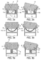
- the pivoting arrangement shown in figure 2a comprises a pivoting member 10, which is pivotally arranged in a cradle 11.
- the cradle 11 is in turn arranged on a supporting structure, here referred to as a base plate 12.
- the pivoting member 10 is adapted to support a shaving head (not shown), and may be provided with a pre-trimmer (not shown).
- the pivoting member 10 may be pivotable around a point or axis A.
- the pivoting member may rest on a suspension point or axle, which it is pivotable around. Alternatively it may be guided by e.g. grooves in the cradle 11, so as to be pivotable around an imaginary pivoting point or axis.
- the pivoting member 10 is spring loaded by a spring loading arrangement 13, arranged to exert a force on both the cradle and the pivoting member.
- the spring loading arrangement can interact with the pivoting member 10 in at least two points of action 14a, 14b, to allow exertion of force in at least two directions of rotation around the pivoting axis A. If the pivoting member is pivotable around a point, the spring loading arrangement can preferably interact with the pivoting member in at least three points of action.
- the spring loading arrangement 13 comprises two coil springs 15a, 15b that are clamped between the cradle 11 and the base plate 12. As the cradle 11 is fixed in relation to the base plate 12, the springs can exert a force on both the cradle 11 and the pivoting member 10.
- the spring loading arrangement may further comprise a force reliving structure.
- the force relieving structure here comprises two abutments 16 formed by protruding portions of the cradle 11, against which the springs are preloaded.
- the abutments 16 are located so that the pivoting member 10 in the resting position will be in level with the abutments. A surface 10a of the pivoting member 10 will thus be immediately adjacent, and possibly in contact with, the preloaded springs.
- the pivoting member 10 has now been rotated around the axis A, and brought out of its resting position.
- the surface 10a of the pivoting member has then moved away from the abutment 16 against which the spring 15a abuts, and this spring 15 is therefore prevented from interacting with the pivoting member 10.
- the spring 15b has been further depressed by the surface 10a of the pivoting member, and therefore exerts a force F on the pivoting member 10 in the point of action 14b, acting to return the pivoting member to the resting position.
- the springs 15a, 15b in figure 2a-b also could be arranged above the points of actions, so that the spring on the left side is depressed as this part of the pivoting member 10 moves upwards (in the reference frame of figure 2b ).
- the springs 15a and 15b are arranged between the base plate 12 and the cradle 11, other configurations are possible as well. E.g. configurations wherein the springs are located at the top sides of the cradle
- the two springs have been substituted by one spring 17, arranged with each of its two ends 17a, 17b in one of the points of action 14a, 14b.
- the function of the spring and abutments is very similar to that described with reference to figure 2a-b .
- the pivoting member 10 when the pivoting member 10 is rotated around the axis A, the left end 17a of the spring 17 abuts against the abutment 16.
- the right end 17b of the spring 17 is depressed by the pivoting member 10, and therefore exerts a force F on the pivoting member 10 in the point of action 14b, acting to return the pivoting member to the resting position.
- the spring loading arrangement comprises a force transfer element in the form of a plate 18, preloaded against the abutments 16 by a single spring element 15.
- a force transfer element in the form of a plate 18, preloaded against the abutments 16 by a single spring element 15.
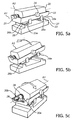
- FIG. 5a-c shows a further embodiment, according to which the pivoting arrangement is able to allow the pivoting member 20 to pivot around two different axes.
- the pivoting member 20 is suspended by two axles 21 in the cradle 22, so as to be pivotable around a first axis A1.
- the cradle is then in itself supported by the supporting structure, here referred to as an outer cradle 23, to be pivotable around a second axis A2.
- the cradle 22 can be guided by grooves (not shown) in the outer cradle 23, so as to be movable in relation to the outer cradle 23, or be suspended by additional axles 24.
- the spring loading arrangement in figure 5 comprises a leaf spring 26, which is fixed to the underside 22a of the cradle 22 by two clamps 27, preferably preloading the leaf spring 26 against the cradle 22.
- the two ends 26a, 26b of the leaf spring are arranged to be located immediately adjacent to the surface 23a of the outer cradle 23.
- the pivoting member is rotated ( figure 5b )
- one end 26a of the leaf spring is "lifted” so as to lose contact with the surface of the outer cradle 23.
- the other end 26b is pressed more firmly against the outer cradle 23, and will cause the leaf spring 26 to exert a force on the cradle 22 acting to return it to the resting position.
- leaf spring 26 could be replaced by two or more leaf springs, each having only one point of action with the pivoting member.
- the spring arrangement in figure 5 further comprises a torsion spring 28, arranged around the axle stub 21 of the pivoting member 20, and preloaded in one rotational direction by abutments 29 on the inner wall of the cradle 22.
- the pivoting member 20 is also provided with abutments 30a-b on either side of the spring 28, arranged to cooperate with the torsion spring when the pivoting member 20 is rotated.
- Figure 5c illustrates rotation of the pivoting member 20.
- One of the abutments 30a is moved towards and compresses the torsion spring, thus creating a force acting to return the pivoting member to its resting position.
- the other abutment 30b is moved out of contact with the torsion spring, which on this side remains preloaded against the abutment 29.
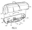
- Figure 6 is a perspective view of a pivoting arrangement similar to that in figure 5a-c , where the upper part, including the pivoting member 20 and the cradle 22, has been exploded away from the outer cradle 23.
- the leaf spring is formed by an oval shaped metal element 32 .
- This spring element 32 is fixed to the outer cradle 23 by a holder in the form of a metal plate 33, which is fixed (by screws or the like) to the outer cradle 23.
- the outer ends 33a, 33b of the plate 33 are formed to grip the ends 32a, 32b of the spring element 32, thereby acting as abutments that pretension the element 32.
- the cradle 22 is arranged to be guided by the edges 34 of the outer cradle, to be pivotable around an axis A2. Further, the underside of the cradle 22 is arranged to rest on the oval element, at points of action on either end of the spring element 32.
- spring element 32 in figure 6 is oriented in an opposite fashion compared to the leaf spring 26 in figure 5 , but has an otherwise similar function.
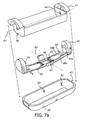
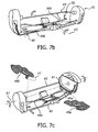
- FIG 7a shows yet another embodiment of a double axis pivoting arrangement according to the present invention.
- the pivoting arrangement here comprises a pivoting member 41, a cradle 42, and an outer cradle 43.
- the cradle has two axles 53, arranged to cooperate with holes 54 in the pivoting member 41, to allow rotation of the pivoting member 41 around an axis A1.
- the cradle has two axles 51 arranged to cooperate with holes 52 in the outer cradle 43, to allow rotation of the cradle 42 around an axis A2.
- the spring loading arrangement is formed by two spring elements 44, each in the form of a substantially U-shaped wire, fitted to the cradle by means of protrusions 45 cooperating with the wire to hold it in place, e.g. by snap fitting.
- Each wire 44 is arranged with its legs 46a, 46b extending from the center of the cradle towards its outer ends.
- One of the legs 46a extends into an elongated grove 47 in an end plate 48 of the cradle 42, and is preloaded to abut against the outer edge 47a of this grove.
- the underside of the pivoting member 41 further has an indentation 48 that is formed to cooperate with the leg 46a.
- the other leg 46b has an end portion 49 that is bent outwards, and adapted to, when the cradle 42 is mounted in the outer cradle 43, extend into a groove 50 in the outer cradle, and be in contact with the upper edge of the groove 50.
- the two legs 46b will serve as a spring loading arrangement similar to that described in relation to figure 5a and 5b .
- the end portion 49 of the leg 46b will be pressed against the upper edge of the groove 50, thus causing a force to be exerted on the cradle 42 to return it to the resting position.
- the portion 49 will be brought out of contact with the groove 50, thus preventing any force to be exerted.
Priority Applications (1)
| Application Number | Priority Date | Filing Date | Title |
|---|---|---|---|
| EP10727900.2A EP2435218B1 (en) | 2009-05-28 | 2010-05-21 | Pivoting arrangement |
Applications Claiming Priority (3)
| Application Number | Priority Date | Filing Date | Title |
|---|---|---|---|
| EP09161317 | 2009-05-28 | ||
| PCT/IB2010/052267 WO2010136943A1 (en) | 2009-05-28 | 2010-05-21 | Pivoting arrangement |
| EP10727900.2A EP2435218B1 (en) | 2009-05-28 | 2010-05-21 | Pivoting arrangement |
Publications (2)
| Publication Number | Publication Date |
|---|---|
| EP2435218A1 EP2435218A1 (en) | 2012-04-04 |
| EP2435218B1 true EP2435218B1 (en) | 2014-03-12 |
Family
ID=42666324
Family Applications (1)
| Application Number | Title | Priority Date | Filing Date |
|---|---|---|---|
| EP10727900.2A Active EP2435218B1 (en) | 2009-05-28 | 2010-05-21 | Pivoting arrangement |
Country Status (9)
| Country | Link |
|---|---|
| US (1) | US9676108B2 (ru) |
| EP (1) | EP2435218B1 (ru) |
| JP (1) | JP5615911B2 (ru) |
| KR (1) | KR101701710B1 (ru) |
| CN (1) | CN102448684B (ru) |
| BR (1) | BRPI1008275B1 (ru) |
| CA (1) | CA2763243C (ru) |
| RU (1) | RU2536851C2 (ru) |
| WO (1) | WO2010136943A1 (ru) |
Cited By (4)
| Publication number | Priority date | Publication date | Assignee | Title |
|---|---|---|---|---|
| EP3300849A1 (en) | 2016-09-28 | 2018-04-04 | Braun GmbH | Electric shaver |
| EP3300854A1 (en) | 2016-09-28 | 2018-04-04 | Braun GmbH | Electric shaver |
| EP3300843A1 (en) | 2016-09-28 | 2018-04-04 | Braun GmbH | Electric shaver |
| WO2018060890A1 (en) | 2016-09-28 | 2018-04-05 | Braun Gmbh | Electric shaver |
Families Citing this family (55)
| Publication number | Priority date | Publication date | Assignee | Title |
|---|---|---|---|---|
| US8455648B2 (en) * | 2008-04-24 | 2013-06-04 | Abbott Gmbh & Co. Kg | 1-(7-(hexahydropyrrolo [3,4-c] pyrrol-2 (1H)-yl) quinolin-4-yl) -3- (pyrazin-2-yl) urea derivatives and related compounds as glycogen synthase kinase 3 (GSK-3) |
| US20110252646A1 (en) * | 2008-10-29 | 2011-10-20 | Bic-Violex Sa | Razor handle having a pivotable retractable shaving head carrier and razor having such a handle |
| US20100313426A1 (en) * | 2009-06-12 | 2010-12-16 | Terence Gordon Royle | Safety razor with pivot and rotation |
| US8474144B2 (en) * | 2009-08-12 | 2013-07-02 | The Gillette Company | Safety razor with rotational movement and locking button |
| US8745883B2 (en) | 2010-09-29 | 2014-06-10 | The Gillette Company | Razor handle with a rotatable portion |
| US8745882B2 (en) | 2010-09-29 | 2014-06-10 | The Gillette Company | Flexible and separable portion of a razor handle |
| EP2508309B1 (en) | 2011-04-05 | 2016-08-03 | The Gillette Company | Razor handle with a rotatable portion |
| JP2013075068A (ja) * | 2011-09-30 | 2013-04-25 | Panasonic Corp | 除毛装置 |
| US20130081290A1 (en) * | 2011-10-03 | 2013-04-04 | Matthew Frank Murgida | Razor handle with a rotatable portion |
| AR089955A1 (es) * | 2012-02-15 | 2014-10-01 | Theravance Inc | Proceso para preparar compuestos de acido 4-amino-5-bifenil-4-il-2-hidroximetil-2-metil-pentanoico |
| US8938885B2 (en) | 2012-05-01 | 2015-01-27 | The Gillette Company | Razor handle with a rotatable portion |
| US9283685B2 (en) * | 2012-07-26 | 2016-03-15 | Shavelogic, Inc. | Pivoting razors |
| US9486930B2 (en) | 2012-09-27 | 2016-11-08 | Shavelogic, Inc. | Shaving systems |
| WO2014051842A1 (en) | 2012-09-27 | 2014-04-03 | Shavelogic, Inc. | Shaving systems |
| WO2014051843A1 (en) | 2012-09-28 | 2014-04-03 | Shavelogic, Inc. | Shaving systems |
| US9623575B2 (en) | 2012-12-18 | 2017-04-18 | Shavelogic, Inc. | Shaving systems |
| CA2922308A1 (en) * | 2013-09-15 | 2015-03-19 | Radiancy Inc. | Hair shaving apparatus with adjustable head angle |
| US20150158192A1 (en) | 2013-12-09 | 2015-06-11 | Shavelogic, Inc. | Multi-material pivot return for shaving systems |
| CA2937701A1 (en) * | 2014-02-28 | 2015-09-03 | Bic-Violex Sa | A razor handle comprising inserts within holes and razor comprising such a razor handle |
| NL2012333B1 (en) * | 2014-02-28 | 2015-10-19 | MCI (Mirror Controls International) Netherlands B V | Mirror adjustment mechanism, in particular for a wing mirror for a motor vehicle. |
| US11325270B2 (en) | 2014-03-21 | 2022-05-10 | Sl Ip Company Llc | Metal spring return and method |
| CN105310754A (zh) * | 2015-02-04 | 2016-02-10 | 江苏怡龙医疗科技有限公司 | 适用于手术机器人的恒推力匀速切割骨科电锯机构 |
| US20170165853A1 (en) * | 2015-12-15 | 2017-06-15 | Yvonne Chee On Li | Razor with mirror |
| US10045795B2 (en) * | 2016-04-07 | 2018-08-14 | Soft Lines International, Ltd. | Handheld cosmetic device with pivoting head |
| CN106042013B (zh) * | 2016-05-19 | 2017-10-31 | 绍兴云疆网络科技服务有限公司 | 一种胳肢窝全自动刮毛保健一体机 |
| US10652956B2 (en) | 2016-06-22 | 2020-05-12 | The Gillette Company Llc | Personal consumer product with thermal control circuitry and methods thereof |
| EP3300845B1 (en) * | 2016-09-28 | 2019-10-23 | Braun GmbH | Shaver coupling and electrical shaver with coupling |
| EP3300861B1 (en) | 2016-09-28 | 2019-07-03 | Braun GmbH | Electrically driven device |
| EP3300844B1 (en) | 2016-09-28 | 2020-04-15 | Braun GmbH | Electric shaver |
| EP3351358B1 (en) | 2017-01-20 | 2019-11-20 | The Gillette Company LLC | Heating delivery element for a shaving razor |
| ES2900466T3 (es) * | 2017-10-06 | 2022-03-17 | Braun Gmbh | Depiladora |
| KR101887119B1 (ko) * | 2017-11-21 | 2018-08-09 | 주식회사 도루코 | 면도기 조립체 |
| EP3546149B1 (en) | 2018-03-27 | 2021-05-12 | Braun GmbH | Hair removal device |
| EP3546148B1 (en) | 2018-03-27 | 2022-01-12 | Braun GmbH | Personal care device |
| EP3546151A1 (en) | 2018-03-27 | 2019-10-02 | Braun GmbH | Personal care device |
| EP3546150B1 (en) | 2018-03-27 | 2021-10-27 | Braun GmbH | Personal care device |
| WO2019191163A1 (en) * | 2018-03-30 | 2019-10-03 | The Gillette Company Llc | Razor handle with a pivoting portion |
| USD874061S1 (en) | 2018-03-30 | 2020-01-28 | The Gillette Company Llc | Shaving razor cartridge |
| JP2021517492A (ja) * | 2018-03-30 | 2021-07-26 | ザ ジレット カンパニー リミテッド ライアビリティ カンパニーThe Gillette Company Llc | 枢動部分を有するかみそりハンドル |
| US20190299464A1 (en) | 2018-03-30 | 2019-10-03 | The Gillette Company Llc | Shaving razor cartridge |
| EP3774224A1 (en) * | 2018-03-30 | 2021-02-17 | The Gillette Company LLC | Razor handle with a pivoting portion |
| CA3091484A1 (en) * | 2018-03-30 | 2019-10-03 | The Gillette Company Llc | Shaving razor system including skin interconnect member |
| US11607820B2 (en) | 2018-03-30 | 2023-03-21 | The Gillette Company Llc | Razor handle with movable members |
| CA3091275A1 (en) | 2018-03-30 | 2019-10-03 | The Gillette Company Llc | Razor handle with a pivoting portion |
| EP3546156B1 (en) | 2018-03-30 | 2021-03-10 | The Gillette Company LLC | Razor handle with a pivoting portion |
| AU2019242768B2 (en) | 2018-03-30 | 2022-03-10 | The Gillette Company Llc | Razor handle with movable members |
| EP3774229A1 (en) | 2018-03-30 | 2021-02-17 | The Gillette Company LLC | Razor handle with a pivoting portion |
| WO2019190963A1 (en) * | 2018-03-30 | 2019-10-03 | The Gillette Company Llc | Razor handle with a pivoting portion |
| EP3774230A1 (en) | 2018-03-30 | 2021-02-17 | The Gillette Company LLC | Razor handle with a pivoting portion |
| BR112020020126A2 (pt) * | 2018-03-30 | 2021-04-06 | The Gillette Company Llc | Cabo de aparelho de barbear ou depilar com uma porção articulada |
| WO2019191178A1 (en) | 2018-03-30 | 2019-10-03 | The Gillette Company Llc | Razor handle with movable members |
| KR102154856B1 (ko) * | 2018-12-11 | 2020-09-10 | 주식회사 도루코 | 면도기 조립체 |
| EP3804926A1 (en) * | 2019-10-11 | 2021-04-14 | Koninklijke Philips N.V. | Hair-cutting unit for use in a hair-cutting appliance |
| JP2022155367A (ja) * | 2021-03-30 | 2022-10-13 | パナソニックIpマネジメント株式会社 | 電気かみそり |
| EP4112247A1 (en) | 2021-07-02 | 2023-01-04 | Koninklijke Philips N.V. | A mounting assembly |
Family Cites Families (48)
| Publication number | Priority date | Publication date | Assignee | Title |
|---|---|---|---|---|
| US2331466A (en) * | 1938-06-21 | 1943-10-12 | Remington Rand Inc | Electric dry shaver |
| US2386536A (en) * | 1944-04-03 | 1945-10-09 | Bensel Duryea | Safety razor |
| US2793430A (en) * | 1955-01-26 | 1957-05-28 | Sperry Rand Corp | Dry shaver cutter heads |
| US2859513A (en) * | 1956-06-28 | 1958-11-11 | Schick Inc | Electric shaver shearing head assembly |
| US3144571A (en) * | 1960-12-23 | 1964-08-11 | Sunbeam Corp | Electromagnetic motor having oppositely oscillating armatures |
| DE1168290B (de) * | 1962-07-18 | 1964-04-16 | Braun Ag | Motorisch betriebener Trockenrasierapparat |
| US3166842A (en) * | 1963-09-13 | 1965-01-26 | Schick Electric Inc | Adjustable spacer bar for multiplehead electric shaver |
| US3339277A (en) * | 1965-04-02 | 1967-09-05 | Sperry Rand Corp | Cutter head assembly for dry shaver having skin undulating means |
| US3321831A (en) * | 1965-06-29 | 1967-05-30 | Cambridge Scient Ind Inc | Razor with a reciprocating blade |
| AT264319B (de) * | 1966-08-12 | 1968-08-26 | Carinthia Elektrogeraete Ges M | Scherkopf für Trockenrasierapparate |
| US3521093A (en) * | 1968-07-26 | 1970-07-21 | Braun Ag | Oscillating motor driving arrangement |
| US3593416A (en) * | 1968-10-10 | 1971-07-20 | Roger C Edson | Safety razor |
| US3552010A (en) * | 1969-01-13 | 1971-01-05 | Sperry Rand Corp | Auxiliary cutter means for an electric dry shaver |
| AT313750B (de) * | 1972-03-01 | 1974-01-15 | Philips Nv | Scherkopf fuer trockenrasierapparate |
| NL7404655A (nl) * | 1974-04-05 | 1975-10-07 | Philips Nv | Droogscheerapparaat met heen en weer aandrijf- baar snijblok. |
| GB8626631D0 (en) * | 1986-11-07 | 1986-12-10 | Gillette Co | Dry shavers |
| ATE69192T1 (de) * | 1988-09-08 | 1991-11-15 | Wilkinson Sword Gmbh | Rasierapparat. |
| JPH085001Y2 (ja) * | 1990-06-01 | 1996-02-14 | ホーヤ株式会社 | 玉摺機の型板保持装置 |
| US5050301A (en) * | 1990-09-19 | 1991-09-24 | The Gillette Company | Razor assembly |
| ES2360262T3 (es) * | 1991-11-27 | 2011-06-02 | The Gillette Company | Máquinas de afeitar. |
| US5185926A (en) * | 1992-02-07 | 1993-02-16 | Remington Products, Inc. | Multiple foil and cutting blade assembly for electric dry shavers |
| GB9208098D0 (en) * | 1992-04-13 | 1992-05-27 | Gillette Co | Razor with movable cartridge |
| US5398412A (en) * | 1992-04-23 | 1995-03-21 | Matsushita Electric Works, Ltd. | Reciprocatory dry shaver |
| JP2546555Y2 (ja) * | 1992-10-29 | 1997-09-03 | 本田技研工業株式会社 | 塗料攪拌機 |
| US5787593A (en) * | 1995-11-29 | 1998-08-04 | Warner-Lambert Company | Pivoting shaving system |
| US5953825A (en) * | 1996-01-16 | 1999-09-21 | The Gillette Company | Safety razors |
| DE19736776C2 (de) * | 1997-08-23 | 1999-06-02 | Braun Gmbh | Trockenrasierapparat |
| US5953824A (en) * | 1997-09-23 | 1999-09-21 | Warner-Lambert Company | Razors providing pivoting and swivelling razor head support |
| JP3749368B2 (ja) * | 1997-12-26 | 2006-02-22 | 帝国通信工業株式会社 | シーソー式電子部品 |
| AT2988U1 (de) | 1998-07-24 | 1999-08-25 | Payer Lux Elektroprod | Trockenrasierapparat |
| DE19859017C1 (de) * | 1998-12-21 | 2000-02-03 | Braun Gmbh | Haarschneidemaschine |
| ATE235354T1 (de) | 1999-11-29 | 2003-04-15 | Koninkl Philips Electronics Nv | Rasierer versehen mit einem rasierkopf, einem hilfsrahmen und einem hauptrahmen |
| WO2001051260A1 (de) * | 2000-01-14 | 2001-07-19 | Payer Elektroprodukte Ges.M.B.H. | Elektrischer rasierapparat |
| US6442850B1 (en) * | 2001-02-28 | 2002-09-03 | Pfizer Inc. | Shaving razor using blade cartridge and blade cartridge therefor |
| JP2004519297A (ja) | 2001-03-27 | 2004-07-02 | コーニンクレッカ フィリップス エレクトロニクス エヌ ヴィ | ノイズ防止キャップを備えたパーソナルケア装置 |
| DE60206070T2 (de) * | 2001-11-15 | 2006-06-14 | Matsushita Electric Works Ltd | Trockenrasierer mit schwenkbarem kopf |
| US7152512B1 (en) * | 2002-04-18 | 2006-12-26 | American Safety Razor | Razor handle with spring fingers |
| US7472483B2 (en) * | 2002-05-07 | 2009-01-06 | Koninklijke Philips Electronics N.V. | Shaving apparatus with spring-mounted shaving head holder |
| US20040181953A1 (en) * | 2003-02-25 | 2004-09-23 | Eveready Battery Company, Inc. | Shaving implement |
| DE10330205A1 (de) * | 2003-07-03 | 2005-01-27 | Braun Gmbh | Elektrisches Haarschneidegerät |
| EP1641606A1 (en) * | 2003-07-07 | 2006-04-05 | Eveready Battery Company, Inc. | Pivotable shaving cartridge and razor including same |
| JP3972903B2 (ja) * | 2003-12-26 | 2007-09-05 | 松下電工株式会社 | 電気かみそり |
| JP4725103B2 (ja) * | 2004-12-28 | 2011-07-13 | パナソニック電工株式会社 | 往復式電気かみそり |
| JP4229091B2 (ja) * | 2005-05-31 | 2009-02-25 | パナソニック電工株式会社 | 体毛処理器具 |
| JP4715425B2 (ja) | 2005-09-27 | 2011-07-06 | パナソニック電工株式会社 | 電気かみそり |
| JP2007151925A (ja) | 2005-12-07 | 2007-06-21 | Izumi Products Co | ロータリー式電気かみそり |
| JP4840450B2 (ja) * | 2009-01-16 | 2011-12-21 | パナソニック電工株式会社 | 電気かみそり |
| EP2508309B1 (en) * | 2011-04-05 | 2016-08-03 | The Gillette Company | Razor handle with a rotatable portion |
-
2010
- 2010-05-21 US US13/320,922 patent/US9676108B2/en active Active
- 2010-05-21 CA CA2763243A patent/CA2763243C/en not_active Expired - Fee Related
- 2010-05-21 BR BRPI1008275-1A patent/BRPI1008275B1/pt not_active IP Right Cessation
- 2010-05-21 WO PCT/IB2010/052267 patent/WO2010136943A1/en active Application Filing
- 2010-05-21 RU RU2011153733/02A patent/RU2536851C2/ru active
- 2010-05-21 KR KR1020117030978A patent/KR101701710B1/ko active IP Right Grant
- 2010-05-21 CN CN201080023275.7A patent/CN102448684B/zh active Active
- 2010-05-21 EP EP10727900.2A patent/EP2435218B1/en active Active
- 2010-05-21 JP JP2012512493A patent/JP5615911B2/ja active Active
Cited By (12)
| Publication number | Priority date | Publication date | Assignee | Title |
|---|---|---|---|---|
| EP3300849A1 (en) | 2016-09-28 | 2018-04-04 | Braun GmbH | Electric shaver |
| EP3300854A1 (en) | 2016-09-28 | 2018-04-04 | Braun GmbH | Electric shaver |
| EP3300848A1 (en) | 2016-09-28 | 2018-04-04 | Braun GmbH | Electric shaver |
| EP3300843A1 (en) | 2016-09-28 | 2018-04-04 | Braun GmbH | Electric shaver |
| WO2018060852A1 (en) | 2016-09-28 | 2018-04-05 | Braun Gmbh | Electric shaver |
| WO2018060890A1 (en) | 2016-09-28 | 2018-04-05 | Braun Gmbh | Electric shaver |
| WO2018060849A1 (en) | 2016-09-28 | 2018-04-05 | Braun Gmbh | Electric shaver |
| WO2018060875A1 (en) | 2016-09-28 | 2018-04-05 | Braun Gmbh | Electric shaver |
| WO2018060850A1 (en) | 2016-09-28 | 2018-04-05 | Braun Gmbh | Electric shaver |
| EP3305485A1 (en) | 2016-09-28 | 2018-04-11 | Braun GmbH | Electric shaver |
| US10836056B2 (en) | 2016-09-28 | 2020-11-17 | Braun Gmbh | Electric shaver |
| US10960557B2 (en) | 2016-09-28 | 2021-03-30 | Braun Gmbh | Electric shaver with four joint linkage |
Also Published As
| Publication number | Publication date |
|---|---|
| JP2012527939A (ja) | 2012-11-12 |
| BRPI1008275A2 (pt) | 2016-03-15 |
| US20120060382A1 (en) | 2012-03-15 |
| WO2010136943A1 (en) | 2010-12-02 |
| KR101701710B1 (ko) | 2017-02-03 |
| KR20120027395A (ko) | 2012-03-21 |
| EP2435218A1 (en) | 2012-04-04 |
| BRPI1008275B1 (pt) | 2020-10-20 |
| RU2536851C2 (ru) | 2014-12-27 |
| CN102448684A (zh) | 2012-05-09 |
| CA2763243A1 (en) | 2010-12-02 |
| RU2011153733A (ru) | 2013-07-10 |
| US9676108B2 (en) | 2017-06-13 |
| CN102448684B (zh) | 2015-01-07 |
| CA2763243C (en) | 2016-10-25 |
| JP5615911B2 (ja) | 2014-10-29 |
Similar Documents
| Publication | Publication Date | Title |
|---|---|---|
| EP2435218B1 (en) | Pivoting arrangement | |
| RU2191684C2 (ru) | Структура для поддержки удлиненного лезвийного блока бритвенного устройства | |
| EP3575532B1 (en) | Lifting system for leaves of furniture | |
| RU2097173C1 (ru) | Безопасная бритва | |
| KR102307892B1 (ko) | 조절 가능한 등받이를 구비한 의자 | |
| GB2387531A (en) | Grill device having a space adjusting unit to adjust a space between an upper grill unit and a lower grill unit | |
| JP2015032065A (ja) | 情報処理装置 | |
| EP0563361B1 (en) | Improved cradle assembly for a moveable arm support system | |
| CA2837363A1 (en) | Tilt mechanism for a chair and chair | |
| EP3481257B1 (en) | Tilting mechanism for chairs | |
| JP2002011265A (ja) | 電気かみそり | |
| EP2993553B1 (en) | Angle adjustment mechanism | |
| EP3599940B1 (en) | Articulation mechanism for chairs | |
| CN110730724B (zh) | 脚轮回转限制结构 | |
| JP4702742B2 (ja) | 椅子 | |
| JP2007037600A (ja) | 反力装置及び椅子 | |
| CN112081836B (zh) | 一种虎克铰 | |
| JP5092187B2 (ja) | 髭剃カード | |
| KR20110137211A (ko) | 각도 조절 가능한 지팡이 | |
| JP3101570U (ja) | 回転軸装置 | |
| JP4853896B2 (ja) | 椅子 | |
| KR200203200Y1 (ko) | 액정모니터용 힌지장치 | |
| KR20140001922U (ko) | 책상용 자세 교정대 | |
| KR20240022271A (ko) | 면도기 카트리지 및 면도기 조립체 | |
| HU189816B (en) | Precision click switch |
Legal Events
| Date | Code | Title | Description |
|---|---|---|---|
| PUAI | Public reference made under article 153(3) epc to a published international application that has entered the european phase |
Free format text: ORIGINAL CODE: 0009012 |
|
| 17P | Request for examination filed |
Effective date: 20111228 |
|
| AK | Designated contracting states |
Kind code of ref document: A1 Designated state(s): AL AT BE BG CH CY CZ DE DK EE ES FI FR GB GR HR HU IE IS IT LI LT LU LV MC MK MT NL NO PL PT RO SE SI SK SM TR |
|
| DAX | Request for extension of the european patent (deleted) | ||
| RAP1 | Party data changed (applicant data changed or rights of an application transferred) |
Owner name: KONINKLIJKE PHILIPS N.V. |
|
| GRAP | Despatch of communication of intention to grant a patent |
Free format text: ORIGINAL CODE: EPIDOSNIGR1 |
|
| INTG | Intention to grant announced |
Effective date: 20131011 |
|
| RIN1 | Information on inventor provided before grant (corrected) |
Inventor name: KNOPH, RAY Inventor name: BEUGELS, JOHANNES |
|
| GRAS | Grant fee paid |
Free format text: ORIGINAL CODE: EPIDOSNIGR3 |
|
| GRAA | (expected) grant |
Free format text: ORIGINAL CODE: 0009210 |
|
| AK | Designated contracting states |
Kind code of ref document: B1 Designated state(s): AL AT BE BG CH CY CZ DE DK EE ES FI FR GB GR HR HU IE IS IT LI LT LU LV MC MK MT NL NO PL PT RO SE SI SK SM TR |
|
| REG | Reference to a national code |
Ref country code: GB Ref legal event code: FG4D |
|
| REG | Reference to a national code |
Ref country code: CH Ref legal event code: EP |
|
| REG | Reference to a national code |
Ref country code: AT Ref legal event code: REF Ref document number: 655931 Country of ref document: AT Kind code of ref document: T Effective date: 20140315 |
|
| REG | Reference to a national code |
Ref country code: IE Ref legal event code: FG4D |
|
| REG | Reference to a national code |
Ref country code: DE Ref legal event code: R096 Ref document number: 602010014213 Country of ref document: DE Effective date: 20140424 |
|
| REG | Reference to a national code |
Ref country code: NL Ref legal event code: VDEP Effective date: 20140312 |
|
| PG25 | Lapsed in a contracting state [announced via postgrant information from national office to epo] |
Ref country code: NO Free format text: LAPSE BECAUSE OF FAILURE TO SUBMIT A TRANSLATION OF THE DESCRIPTION OR TO PAY THE FEE WITHIN THE PRESCRIBED TIME-LIMIT Effective date: 20140612 Ref country code: LT Free format text: LAPSE BECAUSE OF FAILURE TO SUBMIT A TRANSLATION OF THE DESCRIPTION OR TO PAY THE FEE WITHIN THE PRESCRIBED TIME-LIMIT Effective date: 20140312 |
|
| REG | Reference to a national code |
Ref country code: AT Ref legal event code: MK05 Ref document number: 655931 Country of ref document: AT Kind code of ref document: T Effective date: 20140312 |
|
| REG | Reference to a national code |
Ref country code: LT Ref legal event code: MG4D |
|
| PG25 | Lapsed in a contracting state [announced via postgrant information from national office to epo] |
Ref country code: SE Free format text: LAPSE BECAUSE OF FAILURE TO SUBMIT A TRANSLATION OF THE DESCRIPTION OR TO PAY THE FEE WITHIN THE PRESCRIBED TIME-LIMIT Effective date: 20140312 Ref country code: CY Free format text: LAPSE BECAUSE OF FAILURE TO SUBMIT A TRANSLATION OF THE DESCRIPTION OR TO PAY THE FEE WITHIN THE PRESCRIBED TIME-LIMIT Effective date: 20140312 Ref country code: FI Free format text: LAPSE BECAUSE OF FAILURE TO SUBMIT A TRANSLATION OF THE DESCRIPTION OR TO PAY THE FEE WITHIN THE PRESCRIBED TIME-LIMIT Effective date: 20140312 |
|
| PG25 | Lapsed in a contracting state [announced via postgrant information from national office to epo] |
Ref country code: LV Free format text: LAPSE BECAUSE OF FAILURE TO SUBMIT A TRANSLATION OF THE DESCRIPTION OR TO PAY THE FEE WITHIN THE PRESCRIBED TIME-LIMIT Effective date: 20140312 Ref country code: HR Free format text: LAPSE BECAUSE OF FAILURE TO SUBMIT A TRANSLATION OF THE DESCRIPTION OR TO PAY THE FEE WITHIN THE PRESCRIBED TIME-LIMIT Effective date: 20140312 |
|
| PG25 | Lapsed in a contracting state [announced via postgrant information from national office to epo] |
Ref country code: IS Free format text: LAPSE BECAUSE OF FAILURE TO SUBMIT A TRANSLATION OF THE DESCRIPTION OR TO PAY THE FEE WITHIN THE PRESCRIBED TIME-LIMIT Effective date: 20140712 Ref country code: BG Free format text: LAPSE BECAUSE OF FAILURE TO SUBMIT A TRANSLATION OF THE DESCRIPTION OR TO PAY THE FEE WITHIN THE PRESCRIBED TIME-LIMIT Effective date: 20140612 Ref country code: NL Free format text: LAPSE BECAUSE OF FAILURE TO SUBMIT A TRANSLATION OF THE DESCRIPTION OR TO PAY THE FEE WITHIN THE PRESCRIBED TIME-LIMIT Effective date: 20140312 Ref country code: EE Free format text: LAPSE BECAUSE OF FAILURE TO SUBMIT A TRANSLATION OF THE DESCRIPTION OR TO PAY THE FEE WITHIN THE PRESCRIBED TIME-LIMIT Effective date: 20140312 Ref country code: BE Free format text: LAPSE BECAUSE OF FAILURE TO SUBMIT A TRANSLATION OF THE DESCRIPTION OR TO PAY THE FEE WITHIN THE PRESCRIBED TIME-LIMIT Effective date: 20140312 Ref country code: RO Free format text: LAPSE BECAUSE OF FAILURE TO SUBMIT A TRANSLATION OF THE DESCRIPTION OR TO PAY THE FEE WITHIN THE PRESCRIBED TIME-LIMIT Effective date: 20140312 Ref country code: CZ Free format text: LAPSE BECAUSE OF FAILURE TO SUBMIT A TRANSLATION OF THE DESCRIPTION OR TO PAY THE FEE WITHIN THE PRESCRIBED TIME-LIMIT Effective date: 20140312 |
|
| PG25 | Lapsed in a contracting state [announced via postgrant information from national office to epo] |
Ref country code: PL Free format text: LAPSE BECAUSE OF FAILURE TO SUBMIT A TRANSLATION OF THE DESCRIPTION OR TO PAY THE FEE WITHIN THE PRESCRIBED TIME-LIMIT Effective date: 20140312 Ref country code: AT Free format text: LAPSE BECAUSE OF FAILURE TO SUBMIT A TRANSLATION OF THE DESCRIPTION OR TO PAY THE FEE WITHIN THE PRESCRIBED TIME-LIMIT Effective date: 20140312 Ref country code: ES Free format text: LAPSE BECAUSE OF FAILURE TO SUBMIT A TRANSLATION OF THE DESCRIPTION OR TO PAY THE FEE WITHIN THE PRESCRIBED TIME-LIMIT Effective date: 20140312 Ref country code: SK Free format text: LAPSE BECAUSE OF FAILURE TO SUBMIT A TRANSLATION OF THE DESCRIPTION OR TO PAY THE FEE WITHIN THE PRESCRIBED TIME-LIMIT Effective date: 20140312 |
|
| REG | Reference to a national code |
Ref country code: DE Ref legal event code: R097 Ref document number: 602010014213 Country of ref document: DE |
|
| PG25 | Lapsed in a contracting state [announced via postgrant information from national office to epo] |
Ref country code: PT Free format text: LAPSE BECAUSE OF FAILURE TO SUBMIT A TRANSLATION OF THE DESCRIPTION OR TO PAY THE FEE WITHIN THE PRESCRIBED TIME-LIMIT Effective date: 20140714 Ref country code: LU Free format text: LAPSE BECAUSE OF FAILURE TO SUBMIT A TRANSLATION OF THE DESCRIPTION OR TO PAY THE FEE WITHIN THE PRESCRIBED TIME-LIMIT Effective date: 20140521 |
|
| REG | Reference to a national code |
Ref country code: CH Ref legal event code: PL |
|
| PLBE | No opposition filed within time limit |
Free format text: ORIGINAL CODE: 0009261 |
|
| STAA | Information on the status of an ep patent application or granted ep patent |
Free format text: STATUS: NO OPPOSITION FILED WITHIN TIME LIMIT |
|
| PG25 | Lapsed in a contracting state [announced via postgrant information from national office to epo] |
Ref country code: LI Free format text: LAPSE BECAUSE OF NON-PAYMENT OF DUE FEES Effective date: 20140531 Ref country code: MC Free format text: LAPSE BECAUSE OF FAILURE TO SUBMIT A TRANSLATION OF THE DESCRIPTION OR TO PAY THE FEE WITHIN THE PRESCRIBED TIME-LIMIT Effective date: 20140312 Ref country code: CH Free format text: LAPSE BECAUSE OF NON-PAYMENT OF DUE FEES Effective date: 20140531 Ref country code: DK Free format text: LAPSE BECAUSE OF FAILURE TO SUBMIT A TRANSLATION OF THE DESCRIPTION OR TO PAY THE FEE WITHIN THE PRESCRIBED TIME-LIMIT Effective date: 20140312 |
|
| 26N | No opposition filed |
Effective date: 20141215 |
|
| REG | Reference to a national code |
Ref country code: IE Ref legal event code: MM4A |
|
| REG | Reference to a national code |
Ref country code: DE Ref legal event code: R097 Ref document number: 602010014213 Country of ref document: DE Effective date: 20141215 |
|
| PG25 | Lapsed in a contracting state [announced via postgrant information from national office to epo] |
Ref country code: IT Free format text: LAPSE BECAUSE OF FAILURE TO SUBMIT A TRANSLATION OF THE DESCRIPTION OR TO PAY THE FEE WITHIN THE PRESCRIBED TIME-LIMIT Effective date: 20140312 |
|
| PG25 | Lapsed in a contracting state [announced via postgrant information from national office to epo] |
Ref country code: IE Free format text: LAPSE BECAUSE OF NON-PAYMENT OF DUE FEES Effective date: 20140521 |
|
| PG25 | Lapsed in a contracting state [announced via postgrant information from national office to epo] |
Ref country code: SI Free format text: LAPSE BECAUSE OF FAILURE TO SUBMIT A TRANSLATION OF THE DESCRIPTION OR TO PAY THE FEE WITHIN THE PRESCRIBED TIME-LIMIT Effective date: 20140312 |
|
| PG25 | Lapsed in a contracting state [announced via postgrant information from national office to epo] |
Ref country code: MT Free format text: LAPSE BECAUSE OF FAILURE TO SUBMIT A TRANSLATION OF THE DESCRIPTION OR TO PAY THE FEE WITHIN THE PRESCRIBED TIME-LIMIT Effective date: 20140312 |
|
| PG25 | Lapsed in a contracting state [announced via postgrant information from national office to epo] |
Ref country code: SM Free format text: LAPSE BECAUSE OF FAILURE TO SUBMIT A TRANSLATION OF THE DESCRIPTION OR TO PAY THE FEE WITHIN THE PRESCRIBED TIME-LIMIT Effective date: 20140312 |
|
| REG | Reference to a national code |
Ref country code: FR Ref legal event code: PLFP Year of fee payment: 7 |
|
| PG25 | Lapsed in a contracting state [announced via postgrant information from national office to epo] |
Ref country code: GR Free format text: LAPSE BECAUSE OF FAILURE TO SUBMIT A TRANSLATION OF THE DESCRIPTION OR TO PAY THE FEE WITHIN THE PRESCRIBED TIME-LIMIT Effective date: 20140613 |
|
| PG25 | Lapsed in a contracting state [announced via postgrant information from national office to epo] |
Ref country code: HU Free format text: LAPSE BECAUSE OF FAILURE TO SUBMIT A TRANSLATION OF THE DESCRIPTION OR TO PAY THE FEE WITHIN THE PRESCRIBED TIME-LIMIT; INVALID AB INITIO Effective date: 20100521 |
|
| REG | Reference to a national code |
Ref country code: FR Ref legal event code: PLFP Year of fee payment: 8 |
|
| REG | Reference to a national code |
Ref country code: FR Ref legal event code: PLFP Year of fee payment: 9 |
|
| PG25 | Lapsed in a contracting state [announced via postgrant information from national office to epo] |
Ref country code: MK Free format text: LAPSE BECAUSE OF FAILURE TO SUBMIT A TRANSLATION OF THE DESCRIPTION OR TO PAY THE FEE WITHIN THE PRESCRIBED TIME-LIMIT Effective date: 20140312 |
|
| PG25 | Lapsed in a contracting state [announced via postgrant information from national office to epo] |
Ref country code: AL Free format text: LAPSE BECAUSE OF FAILURE TO SUBMIT A TRANSLATION OF THE DESCRIPTION OR TO PAY THE FEE WITHIN THE PRESCRIBED TIME-LIMIT Effective date: 20140312 |
|
| PGFP | Annual fee paid to national office [announced via postgrant information from national office to epo] |
Ref country code: TR Payment date: 20210512 Year of fee payment: 12 |
|
| PGFP | Annual fee paid to national office [announced via postgrant information from national office to epo] |
Ref country code: FR Payment date: 20230523 Year of fee payment: 14 Ref country code: DE Payment date: 20220628 Year of fee payment: 14 |
|
| PGFP | Annual fee paid to national office [announced via postgrant information from national office to epo] |
Ref country code: GB Payment date: 20230523 Year of fee payment: 14 |