EP2423646A1 - A rotary encoder and method of assembling the same - Google Patents
A rotary encoder and method of assembling the same Download PDFInfo
- Publication number
- EP2423646A1 EP2423646A1 EP11158670A EP11158670A EP2423646A1 EP 2423646 A1 EP2423646 A1 EP 2423646A1 EP 11158670 A EP11158670 A EP 11158670A EP 11158670 A EP11158670 A EP 11158670A EP 2423646 A1 EP2423646 A1 EP 2423646A1
- Authority
- EP
- European Patent Office
- Prior art keywords
- rotary scale
- rotary
- scale
- hub
- outer shape
- Prior art date
- Legal status (The legal status is an assumption and is not a legal conclusion. Google has not performed a legal analysis and makes no representation as to the accuracy of the status listed.)
- Withdrawn
Links
- 238000000034 method Methods 0.000 title claims description 27
- 230000001678 irradiating effect Effects 0.000 claims abstract description 7
- 238000005520 cutting process Methods 0.000 claims description 7
- XUIMIQQOPSSXEZ-UHFFFAOYSA-N Silicon Chemical compound [Si] XUIMIQQOPSSXEZ-UHFFFAOYSA-N 0.000 description 15
- 229910052710 silicon Inorganic materials 0.000 description 15
- 239000010703 silicon Substances 0.000 description 15
- 230000008569 process Effects 0.000 description 13
- 238000004519 manufacturing process Methods 0.000 description 8
- 239000000853 adhesive Substances 0.000 description 5
- 230000001070 adhesive effect Effects 0.000 description 5
- 239000002390 adhesive tape Substances 0.000 description 5
- 238000010586 diagram Methods 0.000 description 5
- 238000009434 installation Methods 0.000 description 3
- 230000003287 optical effect Effects 0.000 description 3
- 239000011521 glass Substances 0.000 description 2
- 238000012545 processing Methods 0.000 description 2
- 239000004065 semiconductor Substances 0.000 description 2
- 238000009281 ultraviolet germicidal irradiation Methods 0.000 description 2
- 238000011179 visual inspection Methods 0.000 description 2
- 229910052782 aluminium Inorganic materials 0.000 description 1
- XAGFODPZIPBFFR-UHFFFAOYSA-N aluminium Chemical compound [Al] XAGFODPZIPBFFR-UHFFFAOYSA-N 0.000 description 1
- 230000005540 biological transmission Effects 0.000 description 1
- 230000008859 change Effects 0.000 description 1
- 230000007547 defect Effects 0.000 description 1
- 230000002950 deficient Effects 0.000 description 1
- 230000008021 deposition Effects 0.000 description 1
- 230000000994 depressogenic effect Effects 0.000 description 1
- 238000013461 design Methods 0.000 description 1
- 238000001514 detection method Methods 0.000 description 1
- 238000006073 displacement reaction Methods 0.000 description 1
- 230000000694 effects Effects 0.000 description 1
- 238000005530 etching Methods 0.000 description 1
- 230000006872 improvement Effects 0.000 description 1
- 238000011900 installation process Methods 0.000 description 1
- 239000000463 material Substances 0.000 description 1
- 238000005259 measurement Methods 0.000 description 1
- 229910052751 metal Inorganic materials 0.000 description 1
- 239000002184 metal Substances 0.000 description 1
- 238000012986 modification Methods 0.000 description 1
- 230000004048 modification Effects 0.000 description 1
- 230000002035 prolonged effect Effects 0.000 description 1
- 230000009467 reduction Effects 0.000 description 1
- 239000011347 resin Substances 0.000 description 1
- 229920005989 resin Polymers 0.000 description 1
- 238000009966 trimming Methods 0.000 description 1
Images


Classifications
-
- G—PHYSICS
- G01—MEASURING; TESTING
- G01D—MEASURING NOT SPECIALLY ADAPTED FOR A SPECIFIC VARIABLE; ARRANGEMENTS FOR MEASURING TWO OR MORE VARIABLES NOT COVERED IN A SINGLE OTHER SUBCLASS; TARIFF METERING APPARATUS; MEASURING OR TESTING NOT OTHERWISE PROVIDED FOR
- G01D5/00—Mechanical means for transferring the output of a sensing member; Means for converting the output of a sensing member to another variable where the form or nature of the sensing member does not constrain the means for converting; Transducers not specially adapted for a specific variable
- G01D5/26—Mechanical means for transferring the output of a sensing member; Means for converting the output of a sensing member to another variable where the form or nature of the sensing member does not constrain the means for converting; Transducers not specially adapted for a specific variable characterised by optical transfer means, i.e. using infrared, visible, or ultraviolet light
- G01D5/32—Mechanical means for transferring the output of a sensing member; Means for converting the output of a sensing member to another variable where the form or nature of the sensing member does not constrain the means for converting; Transducers not specially adapted for a specific variable characterised by optical transfer means, i.e. using infrared, visible, or ultraviolet light with attenuation or whole or partial obturation of beams of light
- G01D5/34—Mechanical means for transferring the output of a sensing member; Means for converting the output of a sensing member to another variable where the form or nature of the sensing member does not constrain the means for converting; Transducers not specially adapted for a specific variable characterised by optical transfer means, i.e. using infrared, visible, or ultraviolet light with attenuation or whole or partial obturation of beams of light the beams of light being detected by photocells
- G01D5/347—Mechanical means for transferring the output of a sensing member; Means for converting the output of a sensing member to another variable where the form or nature of the sensing member does not constrain the means for converting; Transducers not specially adapted for a specific variable characterised by optical transfer means, i.e. using infrared, visible, or ultraviolet light with attenuation or whole or partial obturation of beams of light the beams of light being detected by photocells using displacement encoding scales
- G01D5/34707—Scales; Discs, e.g. fixation, fabrication, compensation
- G01D5/34715—Scale reading or illumination devices
-
- Y—GENERAL TAGGING OF NEW TECHNOLOGICAL DEVELOPMENTS; GENERAL TAGGING OF CROSS-SECTIONAL TECHNOLOGIES SPANNING OVER SEVERAL SECTIONS OF THE IPC; TECHNICAL SUBJECTS COVERED BY FORMER USPC CROSS-REFERENCE ART COLLECTIONS [XRACs] AND DIGESTS
- Y10—TECHNICAL SUBJECTS COVERED BY FORMER USPC
- Y10T—TECHNICAL SUBJECTS COVERED BY FORMER US CLASSIFICATION
- Y10T29/00—Metal working
- Y10T29/49—Method of mechanical manufacture
- Y10T29/49002—Electrical device making
Definitions
- the present invention relates to a rotary encoder for detecting rotation information such as a rotational speed and a rotational angle of an object to be detected, in particular a rotary encoder suitable for detecting a rotational angle original point of the object to be detected.
- a rotary encoder there is known an optical rotary encoder adapted for detecting absolute position information among rotation information about an object to be detected (Japanese Patent Application Laid-Open No. 2006-214929 ).
- a light emitting element such as an LED provided on a detecting head
- a light detecting element such as a phototransistor
- lights and darks of the received light are counted, thereby measuring the rotation information about the rotary scale.
- the rotary encoder of a type which detects an absolute position (position of an original point) is, in many cases, fabricated by aligning an original point of a rotational angle of the rotary scale with a predetermined position on a rotating body, for example a hub, and performing adjustment by visual inspection or the like.
- a pattern center of the rotary scale and a rotation center of the hub also require a similar adjustment. In this case, centering is achieved by processing a hole and the pattern center of the scale with high accuracy so as to make a clearance relative to a fitting portion of the hub smaller and thus suppressing eccentricity.
- reflecting portion patterns are radially arranged at regular intervals with respect to the pattern center. A part of those patterns is eliminated to provide a missing portion for detecting the position of the original point, which has no reflecting portion pattern. This missing portion is detected by a detecting head, thereby defining a rotational angle original point.
- the rotary scale is disc-shaped and difficult to determine its mounting phase, there is a problem in that, in order to align the original point of the rotary scale with the hub with regard to the original point of the angular direction and to assemble the rotary scale and the hub, many hours for these processes are required. Further, there is a problem in that centering between the rotary scale and the hub also requires many hours or needs improvement for accuracy of an inner diameter of the rotary scale, which leads to prolonged production time.
- a rotary encoder which enables easy centering between a rotary scale and a hub, and further enables easy assembling of the rotary scale and the hub with high accuracy, and to provide a method of assembling the rotary encoder.
- a rotary encoder includes: a rotary scale, which has a predetermined pattern including continuous patterns and a rotational angle original point formed thereon with reference to a pattern center, has a polygonal outer shape, and has the rotational angle original point defined with reference to at least one side of sides of the polygonal outer shape; a hub, which includes projections for abutting the sides of the polygonal outer shape of the rotary scale and positioning the rotary scale; a rotating shaft, which is press-fitted into the hub and rotates coaxially with the pattern center of the rotary scale; and detecting units for irradiating the rotary scale with light and detecting the light reflected by the rotary scale.
- a rotary encoder includes: a rotary scale, which has a predetermined pattern including continuous patterns formed thereon with reference to a pattern center, has a polygonal outer shape, and has a rotational angle phase of the continuous patterns defined with reference to at least one side of sides of the polygonal outer shape; a hub, which includes projections for abutting the sides of the polygonal outer shape of the rotary scale and positioning the rotary scale; a rotating shaft, which is press-fitted into the hub and rotates coaxially with the pattern center of the rotary scale; and detecting units for irradiating the rotary scale with light and detecting the light reflected by the rotary scale.
- a method of assembling a rotary encoder includes: forming a predetermined pattern on a wafer with reference to an orientation flat, the predetermined pattern including continuous patterns and a rotational angle original point with reference to a pattern center; cutting out a rotary scale to have a polygonal outer shape, the rotary scale having the rotational angle original point defined with reference to at least one side of sides of the polygonal outer shape; mounting the rotary scale cut out to a hub which rotates with the rotary scale, in such a manner that the rotary scale abuts projections for positioning provided on the hub; measuring a positional relationship between a rotating shaft, which is press-fitted into the hub and rotates coaxially with the pattern center of the rotary scale, and the projections; and determining dimensions of two sides of the polygonal outer shape of the rotary scale which abut the projections and cutting out the rotary scale from the wafer, with reference to the measured positional relationship.
- a rotary encoder which enables easy centering between the rotary scale and the hub, and further enables easy assembling of the rotary scale and the hub with high accuracy, and a method of assembling the rotary encoder.
- FIG. 1A is a main portion top view illustrating a rotating unit of a rotary encoder according to a first embodiment of the present invention.
- FIG. 1B is a partial side sectional view illustrating the rotary encoder according to the first embodiment of the present invention.
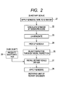
- FIG. 2 is a flow chart of assembling of the rotary encoder according to the first embodiment of the present invention.
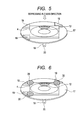
- FIG. 3 is a view illustrating a step 26 of the assembling flow chart.
- FIG. 4 is a plan view illustrating a step 27 of the assembling flow chart.
- FIG. 5 is a perspective view illustrating the step 27 of the assembling flow chart.
- FIG. 6 is a perspective view illustrating a step 28 of the assembling flow chart.
- FIG. 7 is a view illustrating a rotating unit of a rotary encoder according to a second embodiment of the present invention.
- FIG. 8 is a view illustrating a rotating unit of a rotary encoder according to a third embodiment of the present invention.
- FIG. 9A is a view illustrating how to cut out, from a silicon wafer, a rotary scale of a rotary encoder according to a fourth embodiment of the present invention.
- FIG. 9B is a perspective view illustrating a configuration of a rotating unit of the rotary encoder according to the fourth embodiment of the present invention.
- FIG. 10 is a perspective view illustrating a configuration of a rotating unit of a rotary encoder according to a fifth embodiment of the present invention.
- a rotary encoder includes a rotary scale 4, which has a predetermined pattern including continuous patterns 12 and a discontinuous pattern (rotational angle original point) 15 formed thereon with reference to a pattern center (rotation center), and formed from a wafer, for example, a silicon wafer, to have a polygonal outer shape.
- the rotary scale 4 is formed by being cut out from a wafer, for example, a silicon wafer.
- the rotational angle original point is defined with reference to at least one side 11a of sides of the polygonal outer shape of the rotary scale.
- the rotary encoder includes a hub 17, which includes projections 19 for abutting at least two sides, for example, two sides which are nonparallel to each other, of the outer shape of the rotary scale 4 and positioning the rotary scale 4, and which further rotates coaxially with the rotary scale 4.
- the rotary encoder includes a rotating shaft 18, which is press-fitted into the hub 17 and fits with an object to be detected (rotating object) whose rotation information is to be detected.
- the rotary encoder also includes a detecting unit, including a light source for irradiating the rotary scale 4 with light and a light receiver for detecting the light reflected by the rotary scale.
- the rotating shaft 18 has, on a side to which the object to be detected is fitted, a groove 20 for definition of a rotation phase with respect to the rotational angle original point of the rotary scale.
- FIGS. 1A and 1B are a main portion top view and a partial side sectional view, respectively, illustrating a first embodiment of a rotating unit of the rotary encoder according to the present invention.
- the rotary scale 4 has a square outer shape and is made of silicon (Si).
- the rotary scale 4 is of a reflecting type having silicon as a base material, using aluminum for a reflection film, and being fabricated by a semiconductor manufacturing process including deposition, exposure, etching, etc.
- the square rotary scale 4 is adhered to three projections 19 having taller height provided on the hub 17 as a rotating unit made of a resin under a state in which the rotary scale 4 is butted against and aligned with the three projections 19.
- the shaft (rotating shaft) 18 made of a metal is press-fitted into the hub 17.
- the rotary scale 4 is provided with the continuous patterns 12 and the discontinuous portion (discontinuous pattern) 15, for detecting the rotation information.
- the discontinuous portion 15 indicates the rotational angle original point of the rotary scale 4 and is formed in the upper side of the rotary scale 4 in FIG. 1A .
- a tip of the shaft 18 is provided with the groove 20, which performs definition of a phase with and fits with the object to be detected (not shown).
- a direction of the groove 20 is parallel to the discontinuous portion 15 which indicates the angle original point of the rotary scale 4 so that a rotational angle of the shaft relative to the rotary scale 4 of the hub 17 is defined.
- a controller 3 and detecting unit (optical IC) 2 are mounted on a printed board 1.
- Light emitted from the light emitting element (light source) such as an LED of the detecting unit 2 is reflected by the rotary scale 4 and received by the light receiver of the detecting unit 2.
- the controller 3 executes an angle measurement by counting the number of rotations and detecting a direction of the rotation of the rotary scale 4. Details of those operations are disclosed in prior Japanese Patent Application Laid-Open No. 2006-214929 .
- the rotary scale 4 of the reflecting type rotary encoder rotates about the rotation center O, and the continuous patterns 12 are radially arranged at regular intervals.
- First and second detecting units 2a, 2b for detecting reflected light from the rotary scale 4 to obtain position information about the rotary scale 4 are disposed with a mutual angular position difference of 180 degrees with respect to the rotary scale 4.
- the rotational angle original point 15 as the discontinuous pattern is formed instead of a part of the continuous patterns 12 of the rotary scale 4.
- the original point is determined by detecting the rotational angle original point 15.
- the rotational angle original point 15 as the discontinuous pattern is formed by, for example, eliminating one of the continuous patterns 12, or eliminating a few consecutive patterns.
- the first and second detecting units 2a, 2b are similarly configured, and each of which has multiple light receiving sensors for detecting different rotary encoder signals, that is, signals having A-phase, B-phase, A'-phase, and B'-phase, the sensors being arranged, for example, in sets each including four light receiving sensors.
- the rotary scale 4 may include only the continuous patterns 12, and does not need to include the discontinuous pattern (rotational angle original point) 15.
- the rotary scale 4 of the rotary encoder has a predetermined pattern including the continuous patterns 12 formed thereon with reference to the pattern center.
- the rotary scale 4 may be made of the silicon wafer, have the polygonal outer shape, and have a rotational angle phase of the continuous patterns 12 defined with reference to the at least one side 11a of the sides of the polygonal outer shape.
- the hub 17 includes projections 16, 19 for abutting at least two sides 11a, 11b of the outer shape of the rotary scale 4 and positioning the rotary scale 4.
- the rotating shaft 18 is press-fitted into the hub 17 and rotates coaxially with the pattern center of the rotary scale 4.
- the detecting unit 2 irradiates the rotary scale 4 with light and detects the light reflected by the rotary scale 4.
- the rotating shaft 18 is press-fitted into the hub 17, which rotates with the rotary scale 4.
- the rotating shaft 18 fits with the object to be detected whose rotation information is to be detected and rotates coaxially with the rotary scale 4.
- the detecting unit 2 irradiates the rotary scale 4 with light and detects the light reflected by the rotary scale 4.
- FIG. 7 is a main portion explanatory diagram illustrating a second embodiment of a rotating unit of a rotary encoder according to the present invention.
- the basic configuration and behavior of the second embodiment are identical to those of the first embodiment.
- the rotary scale 4 has a rectangular (oblong) outer shape.
- the projections 19 having taller height among all projections are matched in position to the shape of the rotary scale 4, but the configuration is otherwise the same as that of the first embodiment.
- FIG. 8 is a main portion explanatory diagram illustrating a third embodiment of a rotating unit of a rotary encoder according to the present invention.
- the basic configuration and behavior of the third embodiment are identical to those of the first embodiment.
- the rotary scale 4 has a hexagonal outer shape.
- the projection 16 having shorter height and the projections 19 having taller height are matched in position and shape to the outer shape of the rotary scale 4, but the configuration is otherwise the same as that of the first embodiment.
- the hub 17 may advantageously be made smaller in outer shape compared to the square.
- the method of assembling the rotary encoder of the present invention is performed with reference to an orientation flat 32 of the silicon wafer 31.
- the predetermined pattern including the continuous patterns 12 and the discontinuous pattern (rotational angle original point) 15 is formed with reference to the pattern center (rotation center), and the rotary scale having a polygonal outer shape is cut out.
- the rotational angle original point is defined with reference to the at least one side 11a of the sides of the polygonal outer shape.
- the rotary scale 4 thus cut out is mounted to the hub 17, which is to rotate coaxially with the rotary scale 4, in such a manner that the rotary scale 4 abuts the projections 19 for positioning provided on the hub 17, so as to assemble the rotary encoder.
- Position information is measured among two sides 11a, 11b of the outer shape of the rotary scale 4 which abut the projections 19, the projections 19, and a rotating shaft 18 which is press-fitted into the hub 17 and fits with the object to be detected whose rotation information is to be detected. Then, the rotary scale 4 is cut out from the silicon wafer with reference to the measured position information.
- the two sides 11a, 11b are nonparallel to each other.
- a silicon wafer having multiple rotary scales fabricated thereon by a semiconductor process is placed on an adhesive tape larger than the scale size.
- a dicing process 22 the wafer is diced (singulated) by a dicer so as to be divided and cut into individual rotary scale made of silicon.
- the dicing process 22 is controlled to separate the rotary scales made of silicon and keep the adhesive tape unseparated.
- a dicing position is determined accurately in distance from the center of toroidal scale patterns, and the rotary scales are diced with high accuracy.
- the rotary scale is precisely processed so that the distances from two sides of the rotary scale 4, which are orthogonal to each other, to the pattern center have a accuracy of, for example, ⁇ 10 ⁇ m.
- an ultraviolet (UV) irradiation is performed from the rear face so as to decrease an adhesive strength of the adhesive tape.
- the scales are picked up by tweezers.
- a hub press-fitting process 26 is performed.
- the shaft (rotating shaft) 18 is perpendicularly press-fitted into the hub 17.
- a fast curable adhesive 29 is applied to the central portion of the hub 17.
- the installation is performed in such a manner that the two sides 11a, 11b of the rotary scale 4 abut three projections 19 having taller height of the hub 17.
- the installation is accurately performed in such a manner that the rotary scale 4 is depressed also in a Z-direction (direction of the rotating shaft 18), and abuts all the projections 16 having shorter height provided at three positions in the hub 17. Because the projections 16 are shorter in height than the projections 19, the two sides 11a, 11b of the rotary scale 4 placed on the projections 16 abut the projections 19.
- a UV curable adhesive 30 is applied to contact portions between the projections 19 of the hub 17 and the rotary scale 4 so as to cover the contact portions, and then cured by UV light from a UV irradiation device.
- the fast curable adhesive 29 applied to the central portion of the hub 17 is also cured between the hub 17 and the rotary scale 4, as a result of which fixation is finished and the rotary encoder is completed.
- FIGS. 9A and 9B are explanatory diagrams illustrating the method of assembling a rotary encoder according to a fourth embodiment of the present invention.
- the rotary scales 4 are cut out by a dicing saw (not shown).
- Cutting lines 33 for the dicing saw are kept to be parallel or perpendicular to the orientation flat 32, and hence the discontinuous portion 15 as the original point of the rotary scale 4 illustrated in FIG. 9B is always located at the center of one side of cutting faces.
- the shaft 18 is press-fitted into the hub 17, under a state in which the groove 20 of the shaft 18 is aligned with a linear direction of a normal to one side of a scale installation surface defined by the three high projections 19 of the hub 17 passing through the original point.
- the rotary scale 4 is installed and adhered on the hub 17.
- the rotary encoder having the groove 20 of the shaft 18 and the original point direction of the rotary scale 4 aligned with each other is completed.
- the positional relationship is measured among the pattern center of the rotary scale 4, the rotating shaft 18, and the projections 19.
- dimensions of two sides of the outer shape of the rotary scale 4 which abut the projections 19 are determined to cut out the rotary scale 4 from the silicon wafer 31.
- the positional relationship is measured between the rotating shaft 18 and the projections 19 for butting the rotary scale with respect to the shaft center of the hub 17.
- the rotary scale is offset in a direction to compensate a displacement amount thus determined, and subsequently the rotary scale is cut from a silicon wafer so as to assemble the rotary encoder.
- FIG. 10 is an explanatory diagram illustrating the method of assembling the rotary encoder according to the fifth embodiment of the present invention.
- Xh denotes a distance between the center of the hub 17 and the butting portion of the projection 19 in an X-axis direction
- Yh denotes a distance between the center of the hub 17 and the butting portion of the projection 19 in a Y-axis direction
- Xs denotes a distance between the center of the rotary scale 4 and the butting portion of the projection 19 in the X-axis direction
- Ys denotes a distance between the center of the rotary scale 4 and the butting portion of the projection 19 in the Y-axis direction.
- the manufacturing error of the hub 17 may be cancelled if the dicing saw is set out as following.
- the rotary scale having the polygonal outer shape may be used for easily performing the definition of angle and centering during assemblage. Moreover, the need for processing and grinding the outer shape of the rotary scale, which is made of such as glass, in a circular shape is eliminated, and thus easy manufacture of the rotary encoder is achieved.
- the rotating shaft which has directionality, is press-fitted and fixed into the hub, on which the rotary scale having patterns is mounted and which rotates coaxially with the rotary scale.
- the hub requiring a positioning relative to the rotating shaft and the orientation flat or a notch of the silicon wafer, and with reference to the rotating shaft, each component may be assembled into the rotary encoder based on a consistent assembling reference.
- the rotary encoder of the reflecting type is employed in this embodiment, a transmission type may be employed and the detecting unit (optical IC) 2 may have the light receiver and the light emitting portion separate from each other.
- the rotary scale even in a case of a scale made of glass widely used in encoders, a similar effect is obtained by making the scale polygonal in shape.
- a rotary encoder including: a rotary scale, which has a predetermined pattern including continuous patterns and a rotational angle original point formed thereon with reference to a pattern center, has a polygonal outer shape, and has the rotational angle original point defined with reference to at least one side of sides of the polygonal outer shape; a hub, which includes projections for abutting the sides of the polygonal outer shape of the rotary scale and positioning the rotary scale; a rotating shaft, which is press-fitted into the hub and rotates coaxially with the pattern center of the rotary scale; and detecting units for irradiating the rotary scale with light and detecting the light reflected by the rotary scale.
Landscapes
- Physics & Mathematics (AREA)
- General Physics & Mathematics (AREA)
- Optical Transform (AREA)
Applications Claiming Priority (2)
| Application Number | Priority Date | Filing Date | Title |
|---|---|---|---|
| JP2010192264 | 2010-08-30 | ||
| JP2011006510A JP5812246B2 (ja) | 2010-08-30 | 2011-01-15 | ロータリエンコーダの製造方法 |
Publications (1)
| Publication Number | Publication Date |
|---|---|
| EP2423646A1 true EP2423646A1 (en) | 2012-02-29 |
Family
ID=45010601
Family Applications (1)
| Application Number | Title | Priority Date | Filing Date |
|---|---|---|---|
| EP11158670A Withdrawn EP2423646A1 (en) | 2010-08-30 | 2011-03-17 | A rotary encoder and method of assembling the same |
Country Status (3)
| Country | Link |
|---|---|
| US (1) | US8487237B2 (https=) |
| EP (1) | EP2423646A1 (https=) |
| JP (1) | JP5812246B2 (https=) |
Families Citing this family (13)
| Publication number | Priority date | Publication date | Assignee | Title |
|---|---|---|---|---|
| JP5812246B2 (ja) * | 2010-08-30 | 2015-11-11 | キヤノン株式会社 | ロータリエンコーダの製造方法 |
| US9542016B2 (en) | 2012-09-13 | 2017-01-10 | Apple Inc. | Optical sensing mechanisms for input devices |
| WO2015175399A1 (en) * | 2014-05-12 | 2015-11-19 | Phaedrus, Llc | Detecting position of movable object in a device |
| US11512985B2 (en) | 2014-05-12 | 2022-11-29 | Phaedrus, Llc | Control system and method for detecting a position of a movable object |
| US9797752B1 (en) | 2014-07-16 | 2017-10-24 | Apple Inc. | Optical encoder with axially aligned sensor |
| US10190891B1 (en) | 2014-07-16 | 2019-01-29 | Apple Inc. | Optical encoder for detecting rotational and axial movement |
| JP6436674B2 (ja) * | 2014-07-28 | 2018-12-12 | 三菱電機株式会社 | 光学式エンコーダおよび光学式エンコーダの製造方法 |
| US10066970B2 (en) | 2014-08-27 | 2018-09-04 | Apple Inc. | Dynamic range control for optical encoders |
| US9797753B1 (en) * | 2014-08-27 | 2017-10-24 | Apple Inc. | Spatial phase estimation for optical encoders |
| US9952682B2 (en) | 2015-04-15 | 2018-04-24 | Apple Inc. | Depressible keys with decoupled electrical and mechanical functionality |
| JP2019027884A (ja) * | 2017-07-28 | 2019-02-21 | キヤノンプレシジョン株式会社 | 位置検出装置 |
| US11609106B2 (en) | 2018-07-17 | 2023-03-21 | Mitsubishi Electric Corporation | Reflective optical encoder comprising a hub with an adhesive surface with a step structure |
| JP6869393B1 (ja) * | 2020-03-12 | 2021-05-12 | シチズン千葉精密株式会社 | 位置変換器、および検出器の製造方法 |
Citations (2)
| Publication number | Priority date | Publication date | Assignee | Title |
|---|---|---|---|---|
| EP1688711A2 (en) * | 2005-02-04 | 2006-08-09 | Canon Kabushiki Kaisha | Optical encoder |
| US20100171028A1 (en) * | 2009-01-08 | 2010-07-08 | Avago Technologies Ecbu (Singapore) Pte. Ltd. | Reflective Optical Encoder Package and Method |
Family Cites Families (13)
| Publication number | Priority date | Publication date | Assignee | Title |
|---|---|---|---|---|
| US4567467A (en) * | 1984-02-21 | 1986-01-28 | Towmotor Corporation | Angular rotary position encoder |
| JPS61193022A (ja) * | 1985-02-22 | 1986-08-27 | Hitachi Ltd | Z相付エンコ−ダのホ−ムポジシヨン装置 |
| JPH0442729Y2 (https=) * | 1986-10-17 | 1992-10-09 | ||
| JP2571305Y2 (ja) * | 1992-09-07 | 1998-05-18 | 松下電器産業株式会社 | 小型モータの回転数検知装置 |
| JP3486518B2 (ja) * | 1997-02-15 | 2004-01-13 | キヤノン株式会社 | 回転変位情報検出装置 |
| JPH10132611A (ja) * | 1996-11-05 | 1998-05-22 | Canon Inc | 回転変位情報検出装置 |
| JPH10268172A (ja) * | 1997-03-25 | 1998-10-09 | Komatsu Ltd | 光学部品ホルダとこれを用いた共焦点光学装置とホログラムの露光装置及び露光方法 |
| JP2000074693A (ja) * | 1998-09-02 | 2000-03-14 | Canon Inc | 回転変位情報検出装置 |
| JP4078147B2 (ja) * | 2002-08-13 | 2008-04-23 | キヤノン株式会社 | 回転角度検出装置及びその回転ディスク |
| JP4403712B2 (ja) * | 2003-04-07 | 2010-01-27 | セイコーエプソン株式会社 | 半導体装置の製造方法 |
| JP2007168005A (ja) * | 2005-12-21 | 2007-07-05 | Toyota Motor Corp | 切削工具、ホルダ及びスローアウェイチップ |
| JP4882842B2 (ja) * | 2007-04-10 | 2012-02-22 | パナソニック株式会社 | 多方向入力装置 |
| JP5812246B2 (ja) * | 2010-08-30 | 2015-11-11 | キヤノン株式会社 | ロータリエンコーダの製造方法 |
-
2011
- 2011-01-15 JP JP2011006510A patent/JP5812246B2/ja not_active Expired - Fee Related
- 2011-03-17 EP EP11158670A patent/EP2423646A1/en not_active Withdrawn
- 2011-03-17 US US13/050,471 patent/US8487237B2/en not_active Expired - Fee Related
Patent Citations (3)
| Publication number | Priority date | Publication date | Assignee | Title |
|---|---|---|---|---|
| EP1688711A2 (en) * | 2005-02-04 | 2006-08-09 | Canon Kabushiki Kaisha | Optical encoder |
| JP2006214929A (ja) | 2005-02-04 | 2006-08-17 | Canon Inc | 光学式エンコーダ |
| US20100171028A1 (en) * | 2009-01-08 | 2010-07-08 | Avago Technologies Ecbu (Singapore) Pte. Ltd. | Reflective Optical Encoder Package and Method |
Also Published As
| Publication number | Publication date |
|---|---|
| US8487237B2 (en) | 2013-07-16 |
| JP5812246B2 (ja) | 2015-11-11 |
| US20120049051A1 (en) | 2012-03-01 |
| JP2012073219A (ja) | 2012-04-12 |
Similar Documents
| Publication | Publication Date | Title |
|---|---|---|
| US8487237B2 (en) | Rotary encoder and method of assembling the same | |
| US10234308B2 (en) | Encoder, manufacturing method of encoder scale, manufacturing method of encoder, and driving apparatus | |
| US10094684B2 (en) | Method of manufacturing rotary scale, rotary scale, rotary encoder, driving apparatus, image pickup apparatus and robot apparatus | |
| EP2546612B1 (en) | Method for working out the angular position of a rotating element and device for carrying out such a method | |
| JP2012073219A5 (https=) | ||
| JPS60210704A (ja) | 顕微鏡を用いた操作装置の精密校正・整合器具及び方法 | |
| US11935775B2 (en) | Semiconductor manufacturing apparatus and method of manufacturing semiconductor device | |
| JP6369474B2 (ja) | 光学式エンコーダユニット及び光学式エンコーダ | |
| JP5212340B2 (ja) | アブソリュートエンコーダ | |
| US9035232B2 (en) | Method for working out the eccentricity and the angular position of a rotating element and device for carrying out such a method | |
| JP4433759B2 (ja) | アブソリュートエンコーダ | |
| EP1914523A2 (en) | Optical encoder with protective layer | |
| CN110873579A (zh) | 编码器 | |
| CN1755319A (zh) | 对于具有角标度的物体进行制造和安装的方法 | |
| CN1782663A (zh) | 具有角刻度的物体 | |
| JP4343640B2 (ja) | 透明基板の位置合わせ方法 | |
| JP5705326B2 (ja) | 回転軸の位置を決定する方法 | |
| JP5212732B2 (ja) | 光学式エンコーダ | |
| JPH11125540A (ja) | 回転角度検出エンコーダ | |
| JPH0754806Y2 (ja) | 測量機の測角装置に用いられるエンコーダ板支持構造 | |
| CN120958295A (zh) | 编码器用反射型光学式标尺和反射型光学式编码器 | |
| JP2016218004A (ja) | 変位検出装置、および変位検出装置の製造方法 | |
| JP2007248445A (ja) | 有限回転角度検出器およびそれに用いられる回転角度検出板の同心調整装置、並びに回転角度検出板の製造方法 | |
| JP2011252772A (ja) | ガラス基板の形状測定装置及びその方法、並びにガラス基板の製造方法 | |
| JP2007171008A (ja) | 回転角度検出装置 |
Legal Events
| Date | Code | Title | Description |
|---|---|---|---|
| AK | Designated contracting states |
Kind code of ref document: A1 Designated state(s): AL AT BE BG CH CY CZ DE DK EE ES FI FR GB GR HR HU IE IS IT LI LT LU LV MC MK MT NL NO PL PT RO RS SE SI SK SM TR |
|
| AX | Request for extension of the european patent |
Extension state: BA ME |
|
| PUAI | Public reference made under article 153(3) epc to a published international application that has entered the european phase |
Free format text: ORIGINAL CODE: 0009012 |
|
| 17P | Request for examination filed |
Effective date: 20120208 |
|
| RIC1 | Information provided on ipc code assigned before grant |
Ipc: G01D 5/347 20060101AFI20150729BHEP |
|
| GRAP | Despatch of communication of intention to grant a patent |
Free format text: ORIGINAL CODE: EPIDOSNIGR1 |
|
| INTG | Intention to grant announced |
Effective date: 20151007 |
|
| RAP1 | Party data changed (applicant data changed or rights of an application transferred) |
Owner name: CANON KABUSHIKI KAISHA Owner name: CANON PRECISION INC. |
|
| RIN1 | Information on inventor provided before grant (corrected) |
Inventor name: YOKOYAMA, YASUJI Inventor name: KOZUKA, HIRAKU Inventor name: NAGAO, TSUTOMU Inventor name: WATANABE, IKUO Inventor name: NAGURA, CHIHIRO Inventor name: OGURA, MAKOTO Inventor name: HAMASAKI, SATORU Inventor name: IGAKI, MASAHIKO |
|
| STAA | Information on the status of an ep patent application or granted ep patent |
Free format text: STATUS: THE APPLICATION IS DEEMED TO BE WITHDRAWN |
|
| 18D | Application deemed to be withdrawn |
Effective date: 20160218 |