EP2416083B1 - Système et procédé de chauffage de fluide, et système de commande, dispositif de commande et procédé de commande de chauffage de fluide - Google Patents
Système et procédé de chauffage de fluide, et système de commande, dispositif de commande et procédé de commande de chauffage de fluide Download PDFInfo
- Publication number
- EP2416083B1 EP2416083B1 EP09842964.0A EP09842964A EP2416083B1 EP 2416083 B1 EP2416083 B1 EP 2416083B1 EP 09842964 A EP09842964 A EP 09842964A EP 2416083 B1 EP2416083 B1 EP 2416083B1
- Authority
- EP
- European Patent Office
- Prior art keywords
- heaters
- heating capacity
- fluid
- capacity
- heating
- Prior art date
- Legal status (The legal status is an assumption and is not a legal conclusion. Google has not performed a legal analysis and makes no representation as to the accuracy of the status listed.)
- Not-in-force
Links
- 238000010438 heat treatment Methods 0.000 title claims description 164
- 239000012530 fluid Substances 0.000 title claims description 96
- 238000000034 method Methods 0.000 title claims description 8
- 230000001105 regulatory effect Effects 0.000 claims description 32
- 230000001276 controlling effect Effects 0.000 claims description 14
- 239000003507 refrigerant Substances 0.000 claims description 13
- 238000005259 measurement Methods 0.000 claims 2
- XLYOFNOQVPJJNP-UHFFFAOYSA-N water Substances O XLYOFNOQVPJJNP-UHFFFAOYSA-N 0.000 description 97
- 230000007423 decrease Effects 0.000 description 5
- 238000010586 diagram Methods 0.000 description 4
- 230000003247 decreasing effect Effects 0.000 description 2
- 238000001816 cooling Methods 0.000 description 1
- 230000000694 effects Effects 0.000 description 1
- 230000005611 electricity Effects 0.000 description 1
- 238000012423 maintenance Methods 0.000 description 1
Images


Classifications
-
- F—MECHANICAL ENGINEERING; LIGHTING; HEATING; WEAPONS; BLASTING
- F24—HEATING; RANGES; VENTILATING
- F24D—DOMESTIC- OR SPACE-HEATING SYSTEMS, e.g. CENTRAL HEATING SYSTEMS; DOMESTIC HOT-WATER SUPPLY SYSTEMS; ELEMENTS OR COMPONENTS THEREFOR
- F24D11/00—Central heating systems using heat accumulated in storage masses
- F24D11/02—Central heating systems using heat accumulated in storage masses using heat pumps
- F24D11/0214—Central heating systems using heat accumulated in storage masses using heat pumps water heating system
-
- F—MECHANICAL ENGINEERING; LIGHTING; HEATING; WEAPONS; BLASTING
- F24—HEATING; RANGES; VENTILATING
- F24D—DOMESTIC- OR SPACE-HEATING SYSTEMS, e.g. CENTRAL HEATING SYSTEMS; DOMESTIC HOT-WATER SUPPLY SYSTEMS; ELEMENTS OR COMPONENTS THEREFOR
- F24D17/00—Domestic hot-water supply systems
- F24D17/02—Domestic hot-water supply systems using heat pumps
-
- F—MECHANICAL ENGINEERING; LIGHTING; HEATING; WEAPONS; BLASTING
- F24—HEATING; RANGES; VENTILATING
- F24D—DOMESTIC- OR SPACE-HEATING SYSTEMS, e.g. CENTRAL HEATING SYSTEMS; DOMESTIC HOT-WATER SUPPLY SYSTEMS; ELEMENTS OR COMPONENTS THEREFOR
- F24D19/00—Details
- F24D19/10—Arrangement or mounting of control or safety devices
- F24D19/1006—Arrangement or mounting of control or safety devices for water heating systems
- F24D19/1066—Arrangement or mounting of control or safety devices for water heating systems for the combination of central heating and domestic hot water
- F24D19/1072—Arrangement or mounting of control or safety devices for water heating systems for the combination of central heating and domestic hot water the system uses a heat pump
-
- F—MECHANICAL ENGINEERING; LIGHTING; HEATING; WEAPONS; BLASTING
- F24—HEATING; RANGES; VENTILATING
- F24H—FLUID HEATERS, e.g. WATER OR AIR HEATERS, HAVING HEAT-GENERATING MEANS, e.g. HEAT PUMPS, IN GENERAL
- F24H15/00—Control of fluid heaters
- F24H15/10—Control of fluid heaters characterised by the purpose of the control
- F24H15/144—Measuring or calculating energy consumption
-
- F—MECHANICAL ENGINEERING; LIGHTING; HEATING; WEAPONS; BLASTING
- F24—HEATING; RANGES; VENTILATING
- F24H—FLUID HEATERS, e.g. WATER OR AIR HEATERS, HAVING HEAT-GENERATING MEANS, e.g. HEAT PUMPS, IN GENERAL
- F24H15/00—Control of fluid heaters
- F24H15/10—Control of fluid heaters characterised by the purpose of the control
- F24H15/156—Reducing the quantity of energy consumed; Increasing efficiency
-
- F—MECHANICAL ENGINEERING; LIGHTING; HEATING; WEAPONS; BLASTING
- F24—HEATING; RANGES; VENTILATING
- F24H—FLUID HEATERS, e.g. WATER OR AIR HEATERS, HAVING HEAT-GENERATING MEANS, e.g. HEAT PUMPS, IN GENERAL
- F24H15/00—Control of fluid heaters
- F24H15/20—Control of fluid heaters characterised by control inputs
- F24H15/258—Outdoor temperature
-
- F—MECHANICAL ENGINEERING; LIGHTING; HEATING; WEAPONS; BLASTING
- F24—HEATING; RANGES; VENTILATING
- F24H—FLUID HEATERS, e.g. WATER OR AIR HEATERS, HAVING HEAT-GENERATING MEANS, e.g. HEAT PUMPS, IN GENERAL
- F24H15/00—Control of fluid heaters
- F24H15/20—Control of fluid heaters characterised by control inputs
- F24H15/269—Time, e.g. hour or date
-
- F—MECHANICAL ENGINEERING; LIGHTING; HEATING; WEAPONS; BLASTING
- F24—HEATING; RANGES; VENTILATING
- F24H—FLUID HEATERS, e.g. WATER OR AIR HEATERS, HAVING HEAT-GENERATING MEANS, e.g. HEAT PUMPS, IN GENERAL
- F24H15/00—Control of fluid heaters
- F24H15/20—Control of fluid heaters characterised by control inputs
- F24H15/296—Information from neighbouring devices
-
- F—MECHANICAL ENGINEERING; LIGHTING; HEATING; WEAPONS; BLASTING
- F24—HEATING; RANGES; VENTILATING
- F24H—FLUID HEATERS, e.g. WATER OR AIR HEATERS, HAVING HEAT-GENERATING MEANS, e.g. HEAT PUMPS, IN GENERAL
- F24H15/00—Control of fluid heaters
- F24H15/30—Control of fluid heaters characterised by control outputs; characterised by the components to be controlled
- F24H15/375—Control of heat pumps
-
- F—MECHANICAL ENGINEERING; LIGHTING; HEATING; WEAPONS; BLASTING
- F25—REFRIGERATION OR COOLING; COMBINED HEATING AND REFRIGERATION SYSTEMS; HEAT PUMP SYSTEMS; MANUFACTURE OR STORAGE OF ICE; LIQUEFACTION SOLIDIFICATION OF GASES
- F25B—REFRIGERATION MACHINES, PLANTS OR SYSTEMS; COMBINED HEATING AND REFRIGERATION SYSTEMS; HEAT PUMP SYSTEMS
- F25B30/00—Heat pumps
- F25B30/02—Heat pumps of the compression type
-
- F—MECHANICAL ENGINEERING; LIGHTING; HEATING; WEAPONS; BLASTING
- F24—HEATING; RANGES; VENTILATING
- F24D—DOMESTIC- OR SPACE-HEATING SYSTEMS, e.g. CENTRAL HEATING SYSTEMS; DOMESTIC HOT-WATER SUPPLY SYSTEMS; ELEMENTS OR COMPONENTS THEREFOR
- F24D2200/00—Heat sources or energy sources
- F24D2200/12—Heat pump
-
- F—MECHANICAL ENGINEERING; LIGHTING; HEATING; WEAPONS; BLASTING
- F24—HEATING; RANGES; VENTILATING
- F24D—DOMESTIC- OR SPACE-HEATING SYSTEMS, e.g. CENTRAL HEATING SYSTEMS; DOMESTIC HOT-WATER SUPPLY SYSTEMS; ELEMENTS OR COMPONENTS THEREFOR
- F24D2200/00—Heat sources or energy sources
- F24D2200/32—Heat sources or energy sources involving multiple heat sources in combination or as alternative heat sources
-
- F—MECHANICAL ENGINEERING; LIGHTING; HEATING; WEAPONS; BLASTING
- F24—HEATING; RANGES; VENTILATING
- F24H—FLUID HEATERS, e.g. WATER OR AIR HEATERS, HAVING HEAT-GENERATING MEANS, e.g. HEAT PUMPS, IN GENERAL
- F24H15/00—Control of fluid heaters
- F24H15/20—Control of fluid heaters characterised by control inputs
- F24H15/281—Input from user
-
- F—MECHANICAL ENGINEERING; LIGHTING; HEATING; WEAPONS; BLASTING
- F25—REFRIGERATION OR COOLING; COMBINED HEATING AND REFRIGERATION SYSTEMS; HEAT PUMP SYSTEMS; MANUFACTURE OR STORAGE OF ICE; LIQUEFACTION SOLIDIFICATION OF GASES
- F25B—REFRIGERATION MACHINES, PLANTS OR SYSTEMS; COMBINED HEATING AND REFRIGERATION SYSTEMS; HEAT PUMP SYSTEMS
- F25B2400/00—General features or devices for refrigeration machines, plants or systems, combined heating and refrigeration systems or heat-pump systems, i.e. not limited to a particular subgroup of F25B
- F25B2400/06—Several compression cycles arranged in parallel
- F25B2400/061—Several compression cycles arranged in parallel the capacity of the first system being different from the second
-
- Y—GENERAL TAGGING OF NEW TECHNOLOGICAL DEVELOPMENTS; GENERAL TAGGING OF CROSS-SECTIONAL TECHNOLOGIES SPANNING OVER SEVERAL SECTIONS OF THE IPC; TECHNICAL SUBJECTS COVERED BY FORMER USPC CROSS-REFERENCE ART COLLECTIONS [XRACs] AND DIGESTS
- Y02—TECHNOLOGIES OR APPLICATIONS FOR MITIGATION OR ADAPTATION AGAINST CLIMATE CHANGE
- Y02B—CLIMATE CHANGE MITIGATION TECHNOLOGIES RELATED TO BUILDINGS, e.g. HOUSING, HOUSE APPLIANCES OR RELATED END-USER APPLICATIONS
- Y02B30/00—Energy efficient heating, ventilation or air conditioning [HVAC]
- Y02B30/12—Hot water central heating systems using heat pumps
-
- Y—GENERAL TAGGING OF NEW TECHNOLOGICAL DEVELOPMENTS; GENERAL TAGGING OF CROSS-SECTIONAL TECHNOLOGIES SPANNING OVER SEVERAL SECTIONS OF THE IPC; TECHNICAL SUBJECTS COVERED BY FORMER USPC CROSS-REFERENCE ART COLLECTIONS [XRACs] AND DIGESTS
- Y10—TECHNICAL SUBJECTS COVERED BY FORMER USPC
- Y10T—TECHNICAL SUBJECTS COVERED BY FORMER US CLASSIFICATION
- Y10T137/00—Fluid handling
- Y10T137/7722—Line condition change responsive valves
- Y10T137/7737—Thermal responsive
Definitions
- a hot water system in which water is heated by a heat pump unit and the hot water is stored in a tank.
- the control apparatus previously defines the heating capacity by which the COP of each of the plurality of heaters reaches maximum as optimal capacity, and selects heaters out of the plurality of heaters sequentially from a heater of which the optimal capacity is equal to or less than the heating capacity required by the facility and also of which the optimal capacity is closest to the heating capacity required by the facility, and controls each of the plurality of regulating valves in a way that total heating capacity of the selected heaters reaches the heating capacity required by the facility.
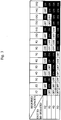
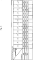
- the above condition is defined as the total COP of all the units reaching the maximum. Therefore, if there are several setting patterns of the heating capacity of each unit, by the setting patterns the total heating capacity of all the units becoming the necessary heating capacity, the determining part 19b selects, out of the setting patterns, a setting pattern by which the total COP of all the units becomes the maximum.
- another definition can be given to the above condition.
- the above condition can be defined as the total COP of all the units being within a predetermined range.
- the above condition can be defined as the total COP of all the units being greater than a predetermined threshold value.
- the hot water system 10 can include, instead of the tank 11, or together with the tank 11, a floor heating appliance, a radiator, or the like.
- the floor heating appliance and the radiator are examples of an appliance using the fluid as heat source.
- the tank 11 and the appliance such as the floor heating appliance or the radiator are examples of a facility.
- the fluid circuit 10a circulates the water between each unit and the facility; however, when the facility is the floor heating, the radiator, or the like, the fluid circuit 10a can circulate fluid other than the water between each unit and facilities.
- the determining part 19b calculates necessary capacity per hour from the temperature and the time set by the user (e.g., when the user can set a "rapid" mode), and the inlet temperature and the outlet temperature of the tank 11.
- the determining part 19b calculates the necessary capacity per hour with considering also the heat discharge amount in the facility.
- the determining part 19b selects a unit to be used with respect to the determined capacity out of the heat pump units 14a, 14b, and 14c, and determines the capacity to be assigned to the respective units.
- the highly efficient operation of the hot water system 10 can be made by selection of the units to be operated and distribution of the capacity of the units.
- the present embodiment can be applied widely with respect to the required capacity. Specifically, the unit to be used is properly selected according to the capacity band of each unit, and thus it is possible to continually maintain the highly efficient operation with respect to the wide variety of the required capacity. Further, according to the present embodiment, the efficient operation can be made at the time of the capacity being low and the operation being difficult by a single large capacity unit.
- Fig. 5 is a table showing a calculation example of a COP of a unit in the present embodiment.
Landscapes
- Engineering & Computer Science (AREA)
- Physics & Mathematics (AREA)
- Thermal Sciences (AREA)
- Mechanical Engineering (AREA)
- General Engineering & Computer Science (AREA)
- Chemical & Material Sciences (AREA)
- Combustion & Propulsion (AREA)
- Heat-Pump Type And Storage Water Heaters (AREA)
Claims (11)
- Système de commande de chauffage d'un fluide comprenant :un circuit de fluide (10a) configuré de façon à faire circuler un fluide entre une pluralité de dispositifs de chauffage (14a, 14b, 14c) configurés de façon à chauffer le fluide, la pluralité de dispositifs de chauffage présentant une propriété selon laquelle la capacité de chauffage varie en fonction de la quantité d'écoulement du fluide, et le COP (coefficient de performance) varie en fonction de la capacité de chauffage, et une installation qui comprend l'un au moins d'un réservoir (11) configuré de façon à stocker le fluide, et d'un appareil configuré de façon à utiliser le fluide en tant que source de chaleur ;une pluralité de soupapes de régulation (13a, 13b, 13c), configurée de façon à réguler la quantité d'écoulement du fluide de chacun de la pluralité de dispositifs de chauffage ; etun appareil de commande (19) configuré de façon à déterminer la capacité de chauffage de chacun de la pluralité des dispositifs de chauffage, de sorte que la capacité de chauffage totale de la pluralité de dispositifs de chauffage, atteigne la capacité de chauffage requise par l'installation, et en outre de sorte, que le COP total de la pluralité de dispositifs de chauffage, satisfasse à une condition prédéterminée, et à commander chacune de la pluralité des soupapes de régulation de telle manière que la capacité de chauffage de chacun de la pluralité des dispositifs de chauffage, atteigne la capacité de chauffage déterminée ;caractérisé par :un dispositif de mesure de la puissance (23) configuré de façon à mesurer la puissance consommée de chacun de la pluralité de dispositifs de chauffage ; etun capteur de température de l'air extérieur (24) configuré de façon à mesurer la température de l'air extérieur ;dans lequel l'appareil de commande, sur la base de la capacité de chauffage déterminée, de la puissance consommée mesurée par le dispositif de mesure de la puissance, et de la température de l'air extérieur mesurée par le capteur de température de l'air extérieur, obtient une relation entre le COP et la capacité de chauffage de chacun de la pluralité de dispositifs de chauffage en fonction de la température de l'air extérieur, et détermine la capacité de chauffage de chacune de la pluralité de dispositifs de chauffage en se rapportant à la relation obtenue.
- Système de commande de chauffage d'un fluide selon la revendication 1,
dans lequel l'appareil de commande permet de déterminer la capacité de chauffage de chacun de la pluralité de dispositifs de chauffage de telle manière que la capacité de chauffage totale de la pluralité de dispositifs de chauffage, atteigne la capacité de chauffage requise par l'installation, et de telle manière en outre que le COP total de la pluralité de dispositifs de chauffage, atteigne une valeur maximum. - Système de chauffage d'un fluide (10) comprenant :le système de commande de chauffage d'un fluide selon la revendication 1 et la revendication 2 ; etune pluralité de dispositifs de chauffage à connecter au système de commande de chauffage d'un fluide.
- Système de chauffage d'un fluide selon la revendication 3,
dans lequel la pluralité de dispositifs de chauffage comprend deux dispositifs de chauffage ou plus, présentant des propriétés différentes. - Système de chauffage d'un fluide selon la revendication 3 et la revendication 4,
dans lequel la pluralité de dispositifs de chauffage comprend deux dispositifs de chauffage ou plus, présentant des capacités de chauffage minimum. - Système de chauffage d'un fluide selon l'une quelconque des revendications 3 à 5,
dans lequel la pluralité de dispositifs de chauffage comprend deux unités de pompe à chaleur ou plus qui font appel à des types de fluide frigorigène différents. - Système de chauffage d'un fluide selon l'une quelconque des revendications 3 à 6,
dans lequel la pluralité de dispositifs de chauffage comprend une unité de pompe à chaleur et un dispositif de chauffage différent de l'unité de pompe à chaleur. - Système de commande de chauffage d'un fluide selon la revendication 1 et la revendication 2,
dans lequel l'appareil de commande permet de définir au préalable la capacité de chauffage grâce à laquelle le COP de chacun de la pluralité de dispositifs de chauffage atteint une valeur maximum en tant que capacité optimale, de sélectionner un groupe de dispositifs de chauffage composé d'un dispositif de chauffage au moins dans la pluralité de dispositifs de chauffage, la capacité optimale totale du ou des dispositifs de chauffage correspondant à la capacité de chauffage requise par l'installation, et de commander chacune de la pluralité des soupapes de régulation de telle manière que la capacité de chauffage totale du ou des dispositifs de chauffage composant le groupe de dispositifs de chauffage sélectionné, atteigne la capacité de chauffage requise par l'installation. - Système de commande de chauffage d'un fluide selon la revendication 1 et la revendication 2,
dans lequel l'appareil de commande permet de définir au préalable la capacité de chauffage grâce à laquelle le COP de chacun de la pluralité des dispositifs de chauffage atteint une valeur maximum en tant que capacité optimale, et de sélectionner des dispositifs de chauffage dans la pluralité de dispositifs de chauffage de manière séquentielle à partir d'un dispositif de chauffage dont la capacité optimale est égale ou inférieure à la capacité de chauffage requise par l'installation, et également dont la capacité optimale est la plus proche de la capacité de chauffage requise par l'installation, et de commander chacune de la pluralité des soupapes de régulation de telle manière que la capacité de chauffage totale des dispositifs de chauffage sélectionnés, atteigne la capacité de chauffage requise par l'installation. - Procédé de chauffage d'un fluide comprenant :une étape consistant à faire circuler un fluide entre une pluralité de dispositifs de chauffage (14a, 14b, 14c) qui chauffent le fluide, la pluralité de dispositifs de chauffage possédant une propriété selon laquelle la capacité de chauffage varie en fonction de la quantité d'écoulement du fluide, et un COP (coefficient de performance) varie en fonction de la capacité de chauffage, et une installation qui comprend l'un au moins d'un réservoir (11) stockant le fluide, et d'un appareil utilisant le fluide en tant que source de chaleur ;une étape consistant à déterminer la capacité de chauffage de chacun de la pluralité des dispositifs de chauffage de telle manière que la capacité de chauffage totale de la pluralité des dispositifs de chauffage, atteigne la capacité de chauffage requise par l'installation, et en outre de telle manière que le COP total de la pluralité de dispositifs, satisfasse à une condition prédéterminée ; etune étape consistant à commander chacune d'une pluralité de soupapes de régulation (13a, 13b, 13c) qui régulent la quantité d'écoulement du fluide de chacun de la pluralité de dispositifs de chauffage de telle manière que la capacité de chauffage de chacun de la pluralité de dispositifs de chauffage, atteigne la capacité de chauffage déterminée ;caractérisé par :une étape de mesure de la puissance consistant à mesurer la puissance consommée de chacun de la pluralité de dispositifs de chauffage ; etune étape de mesure de la température de l'air extérieur consistant à mesurer la température de l'air extérieur ;dans lequel le procédé de chauffage d'un fluide, sur la base de la capacité de chauffage déterminée, de la puissance consommée mesurée lors de l'étape de mesure de la puissance, et de la température de l'air extérieur mesurée lors de l'étape de mesure de la température de l'air extérieur, permet d'obtenir une relation entre le COP et la capacité de chauffage de chacun de la pluralité des dispositifs de chauffage en fonction de la température de l'air extérieur, et de déterminer la capacité de chauffage de chacune de la pluralité des dispositifs de chauffage en se rapportant à la relation obtenue.
- Appareil de commande (19) connecté à une pluralité de soupapes de régulation (13a, 13b, 13c) fixées sur un circuit de fluide (10a) faisant circuler un fluide entre une pluralité de dispositifs de chauffage (14a, 14b, 14c) qui chauffent le fluide, la pluralité de dispositifs de chauffage possédant une propriété selon laquelle la capacité de chauffage varie en fonction de la quantité d'écoulement du fluide, et un COP (coefficient de performance) varie en fonction de la capacité de chauffage, et une installation qui comprend l'un au moins d'un réservoir (11) stockant le fluide, et d'un appareil utilisant le fluide en tant que source de chaleur, l'appareil de commande comprenant :une partie détermination (19b) configurée de façon à déterminer la capacité de chauffage de chacun de la pluralité des dispositifs de chauffage de telle manière que la capacité de chauffage totale de la pluralité des dispositifs de chauffage, atteigne la capacité de chauffage requise par l'installation, et en outre de telle manière que le COP total de la pluralité de dispositifs, satisfasse à une condition prédéterminée ; etune partie commande (19c) configurée de façon à commander chacune de la pluralité des soupapes de régulation de telle manière que la capacité de chauffage de chacun de la pluralité des dispositifs de chauffage, atteigne la capacité de chauffage déterminée ;caractérisé par :une partie détection (19a) configurée de façon à obtenir les données de la puissance consommée mesurée de chacun de la pluralité des dispositifs de chauffage, et de la température de l'air extérieur mesurée ;dans lequel l'appareil de commande, sur la base de la capacité de chauffage déterminée, de la puissance consommée mesurée, et de la température de l'air extérieur mesurée, obtient une relation entre le COP et la capacité de chauffage de chacun de la pluralité des dispositifs de chauffage en fonction de la température de l'air extérieur, et détermine la capacité de chauffage de chacun de la pluralité des dispositifs de chauffage en se rapportant à la relation obtenue.
Applications Claiming Priority (1)
| Application Number | Priority Date | Filing Date | Title |
|---|---|---|---|
| PCT/JP2009/056514 WO2010116454A1 (fr) | 2009-03-30 | 2009-03-30 | Système et procédé de chauffage de fluide, et système de commande, dispositif de commande et procédé de commande de chauffage de fluide |
Publications (3)
| Publication Number | Publication Date |
|---|---|
| EP2416083A1 EP2416083A1 (fr) | 2012-02-08 |
| EP2416083A4 EP2416083A4 (fr) | 2015-11-04 |
| EP2416083B1 true EP2416083B1 (fr) | 2017-05-31 |
Family
ID=42935766
Family Applications (1)
| Application Number | Title | Priority Date | Filing Date |
|---|---|---|---|
| EP09842964.0A Not-in-force EP2416083B1 (fr) | 2009-03-30 | 2009-03-30 | Système et procédé de chauffage de fluide, et système de commande, dispositif de commande et procédé de commande de chauffage de fluide |
Country Status (4)
| Country | Link |
|---|---|
| US (1) | US9500376B2 (fr) |
| EP (1) | EP2416083B1 (fr) |
| JP (1) | JP5132813B2 (fr) |
| WO (1) | WO2010116454A1 (fr) |
Families Citing this family (11)
| Publication number | Priority date | Publication date | Assignee | Title |
|---|---|---|---|---|
| JP2014167352A (ja) * | 2011-05-31 | 2014-09-11 | Toshiba Carrier Corp | 加温システム |
| CN102506519B (zh) * | 2011-10-23 | 2013-12-11 | 重庆市电力公司电力科学研究院 | 热电联产机组与风力发电联合供热系统及调度方法 |
| GB2510547B (en) * | 2012-03-01 | 2016-04-27 | Waste Heat Recovery Ltd | Heat recovery |
| JP5447627B1 (ja) * | 2012-09-26 | 2014-03-19 | ダイキン工業株式会社 | 熱源システム制御装置 |
| US9719687B2 (en) * | 2014-01-21 | 2017-08-01 | Intellihot, Inc. | Multi-temperature output fluid heating system |
| EP3136013B1 (fr) * | 2014-04-25 | 2023-02-22 | Mitsubishi Electric Corporation | Système de refroidissement de pompe à chaleur et procédé de commande associé |
| JP6109119B2 (ja) * | 2014-07-10 | 2017-04-05 | 三菱電機株式会社 | ヒートポンプ給湯システム |
| CN104676902B (zh) * | 2015-03-11 | 2017-06-30 | 广东美的暖通设备有限公司 | 热泵热水器及其控制方法 |
| KR20210108246A (ko) * | 2020-02-25 | 2021-09-02 | 엘지전자 주식회사 | 히트펌프 및 그 동작방법 |
| US20220003447A1 (en) * | 2020-07-01 | 2022-01-06 | Haier Us Appliance Solutions, Inc. | Air conditioning system with improved coordination between a plurality of units |
| WO2024084000A1 (fr) * | 2022-10-20 | 2024-04-25 | Peter Brecklinghaus | Kit de modernisation pour un système de chauffage central existant, et procédé de modernisation d'un système de chauffage central existant à l'aide d'un kit de modernisation |
Family Cites Families (25)
| Publication number | Priority date | Publication date | Assignee | Title |
|---|---|---|---|---|
| DE2906557C2 (de) * | 1979-02-17 | 1984-07-12 | Joh. Vaillant Gmbh U. Co, 5630 Remscheid | Verfahren und Vorrichtung zum Regeln einer Heizungsanlage mit zwei Wärmequellen |
| JPS60243450A (ja) | 1984-05-17 | 1985-12-03 | 三菱電機株式会社 | 給湯・冷暖房ヒ−トポンプ装置 |
| CH667717A5 (de) | 1985-04-23 | 1988-10-31 | Landis & Gyr Ag | Verfahren zur leistungsmaessig gesteuerten inbetriebnahme bzw. abschaltung von heizkesseln. |
| EP0445310A1 (fr) * | 1990-02-09 | 1991-09-11 | Viessmann Werke GmbH & Co. | Procédé et dispositif de régulation de la température "aller" d'un système de chauffage à plusieures chaudières |
| EP0900988A1 (fr) * | 1997-09-06 | 1999-03-10 | Electrowatt Technology Innovation AG | Méthode pour contrÔler une installation de chauffage avec plusieurs générateurs de chaleur |
| JP3758627B2 (ja) * | 2001-11-13 | 2006-03-22 | ダイキン工業株式会社 | ヒートポンプ式給湯装置 |
| JP2003166750A (ja) | 2001-11-30 | 2003-06-13 | Denso Corp | ヒートポンプ式給湯装置 |
| JP3932913B2 (ja) * | 2002-01-29 | 2007-06-20 | ダイキン工業株式会社 | ヒートポンプ式給湯機 |
| JP3742356B2 (ja) * | 2002-03-20 | 2006-02-01 | 株式会社日立製作所 | ヒートポンプ給湯機 |
| JP4305052B2 (ja) | 2003-05-19 | 2009-07-29 | パナソニック株式会社 | ヒートポンプ給湯空調装置 |
| JP4077766B2 (ja) | 2003-06-03 | 2008-04-23 | 松下電器産業株式会社 | ヒートポンプ給湯装置 |
| JP2005090815A (ja) | 2003-09-16 | 2005-04-07 | Matsushita Electric Ind Co Ltd | ヒートポンプ式給湯機 |
| JP4096860B2 (ja) | 2003-10-31 | 2008-06-04 | ダイキン工業株式会社 | ヒートポンプ式給湯装置用の分岐ユニット |
| JP4114613B2 (ja) | 2004-01-27 | 2008-07-09 | 松下電工株式会社 | ヒートポンプ式給湯システム |
| JP4058696B2 (ja) * | 2004-05-28 | 2008-03-12 | 日立アプライアンス株式会社 | ヒートポンプ給湯システム |
| JP2006138493A (ja) * | 2004-11-10 | 2006-06-01 | Hanshin Electric Co Ltd | 貯湯式給湯装置 |
| JP2006283989A (ja) * | 2005-03-31 | 2006-10-19 | Sanyo Electric Co Ltd | 冷暖房システム |
| JP2006292281A (ja) | 2005-04-11 | 2006-10-26 | Denso Corp | ヒートポンプ式給湯装置 |
| JP4545691B2 (ja) | 2006-01-17 | 2010-09-15 | リンナイ株式会社 | 貯湯システム |
| US8733429B2 (en) | 2006-02-13 | 2014-05-27 | The H.L. Turner Group, Inc. | Hybrid heating and/or cooling system |
| JP4753791B2 (ja) | 2006-05-12 | 2011-08-24 | シャープ株式会社 | ヒートポンプ式給湯機 |
| JP2007322084A (ja) | 2006-06-02 | 2007-12-13 | Hitachi Appliances Inc | ヒートポンプ給湯機 |
| AT503582B1 (de) * | 2006-09-04 | 2007-11-15 | Vaillant Austria Gmbh | Verfahren zum betreiben mehrerer durchlauferhitzer |
| DE202007002733U1 (de) * | 2007-02-24 | 2007-06-06 | Gross, Hermann | Anlage zur Erzeugung, Speicherung und Verteilung von Wärmeenergie zwischen wärmetechnischen Betriebsmitteln mit abgestuften Temperaturniveaus in einem Gebäude und Steigerung zum Betrieb einer solchen Anlage |
| EP2098791A1 (fr) * | 2008-03-05 | 2009-09-09 | Roth Werke GmbH | Dispositif de chauffage d'eau |
-
2009
- 2009-03-30 JP JP2011508097A patent/JP5132813B2/ja not_active Expired - Fee Related
- 2009-03-30 US US13/255,689 patent/US9500376B2/en active Active
- 2009-03-30 EP EP09842964.0A patent/EP2416083B1/fr not_active Not-in-force
- 2009-03-30 WO PCT/JP2009/056514 patent/WO2010116454A1/fr active Application Filing
Also Published As
| Publication number | Publication date |
|---|---|
| US20110315093A1 (en) | 2011-12-29 |
| EP2416083A1 (fr) | 2012-02-08 |
| JP5132813B2 (ja) | 2013-01-30 |
| WO2010116454A1 (fr) | 2010-10-14 |
| US9500376B2 (en) | 2016-11-22 |
| EP2416083A4 (fr) | 2015-11-04 |
| JPWO2010116454A1 (ja) | 2012-10-11 |
Similar Documents
| Publication | Publication Date | Title |
|---|---|---|
| EP2416083B1 (fr) | Système et procédé de chauffage de fluide, et système de commande, dispositif de commande et procédé de commande de chauffage de fluide | |
| US20180128502A1 (en) | Water Heater Controller or System | |
| US7658335B2 (en) | Hydronic heating system | |
| US8538597B2 (en) | System and method for regulating temperature in a hot water heater | |
| JP5597767B2 (ja) | 暖房装置および暖房装置の制御方法 | |
| EP2356387B1 (fr) | Systeme de chauffage hybride | |
| EP3136013B1 (fr) | Système de refroidissement de pompe à chaleur et procédé de commande associé | |
| EP2508806B1 (fr) | Système de pompe à chaleur et procédé de commande de l'unité de pompe à chaleur | |
| EP3412985B1 (fr) | Procédé de commande de système de chauffage d'eau, et système de chauffage d'eau | |
| JP5825338B2 (ja) | 給湯制御システム | |
| JP5835278B2 (ja) | 給湯制御システム | |
| EP3346197B1 (fr) | Système de commande de chauffage et système de chauffage d'eau chaude de pompe à chaleur | |
| KR101456878B1 (ko) | 히트펌프 성능평가 시스템의 제어방법 | |
| US20150369547A1 (en) | Energy measurement system for fluid systems | |
| JP3550336B2 (ja) | 冷暖房システム | |
| EP3382490B1 (fr) | Procédé pour commander un système de chauffage hydronique dans plusieurs pièces | |
| JP2009097770A (ja) | ヒートポンプ式温水暖房装置の循環流量算出方法 | |
| JP5907158B2 (ja) | 給湯制御システム | |
| JP2002147775A (ja) | 温水暖房システムにおける試運転制御方法 | |
| Larson et al. | Laboratory Assessment of EcoRuno CO2 Air-to-Water Heat Pump | |
| JP6212990B2 (ja) | 電気機器制御システム | |
| EP4307074A1 (fr) | Dispositif de réglage de température | |
| JP2024135510A (ja) | ヒートポンプ式給湯システム | |
| JPH0776631B2 (ja) | 吸収式冷温水機の運転制御方法 | |
| JP2017227389A (ja) | 貯湯式給湯機 |
Legal Events
| Date | Code | Title | Description |
|---|---|---|---|
| PUAI | Public reference made under article 153(3) epc to a published international application that has entered the european phase |
Free format text: ORIGINAL CODE: 0009012 |
|
| 17P | Request for examination filed |
Effective date: 20110927 |
|
| AK | Designated contracting states |
Kind code of ref document: A1 Designated state(s): AT BE BG CH CY CZ DE DK EE ES FI FR GB GR HR HU IE IS IT LI LT LU LV MC MK MT NL NO PL PT RO SE SI SK TR |
|
| DAX | Request for extension of the european patent (deleted) | ||
| RA4 | Supplementary search report drawn up and despatched (corrected) |
Effective date: 20151001 |
|
| RIC1 | Information provided on ipc code assigned before grant |
Ipc: F24D 19/10 20060101ALI20150925BHEP Ipc: F24D 17/02 20060101ALI20150925BHEP Ipc: F24D 11/02 20060101ALI20150925BHEP Ipc: F24H 1/00 20060101AFI20150925BHEP |
|
| 17Q | First examination report despatched |
Effective date: 20160628 |
|
| REG | Reference to a national code |
Ref country code: DE Ref legal event code: R079 Ref document number: 602009046422 Country of ref document: DE Free format text: PREVIOUS MAIN CLASS: F24H0001000000 Ipc: F25B0030020000 |
|
| GRAP | Despatch of communication of intention to grant a patent |
Free format text: ORIGINAL CODE: EPIDOSNIGR1 |
|
| RIC1 | Information provided on ipc code assigned before grant |
Ipc: F24D 19/10 20060101ALI20161130BHEP Ipc: F24D 11/02 20060101ALI20161130BHEP Ipc: F24D 17/02 20060101ALI20161130BHEP Ipc: F25B 30/02 20060101AFI20161130BHEP |
|
| INTG | Intention to grant announced |
Effective date: 20161222 |
|
| GRAS | Grant fee paid |
Free format text: ORIGINAL CODE: EPIDOSNIGR3 |
|
| GRAA | (expected) grant |
Free format text: ORIGINAL CODE: 0009210 |
|
| AK | Designated contracting states |
Kind code of ref document: B1 Designated state(s): AT BE BG CH CY CZ DE DK EE ES FI FR GB GR HR HU IE IS IT LI LT LU LV MC MK MT NL NO PL PT RO SE SI SK TR |
|
| REG | Reference to a national code |
Ref country code: CH Ref legal event code: EP Ref country code: GB Ref legal event code: FG4D |
|
| REG | Reference to a national code |
Ref country code: AT Ref legal event code: REF Ref document number: 897865 Country of ref document: AT Kind code of ref document: T Effective date: 20170615 |
|
| REG | Reference to a national code |
Ref country code: IE Ref legal event code: FG4D |
|
| REG | Reference to a national code |
Ref country code: SE Ref legal event code: TRGR |
|
| REG | Reference to a national code |
Ref country code: DE Ref legal event code: R096 Ref document number: 602009046422 Country of ref document: DE |
|
| REG | Reference to a national code |
Ref country code: NL Ref legal event code: MP Effective date: 20170531 |
|
| REG | Reference to a national code |
Ref country code: LT Ref legal event code: MG4D |
|
| REG | Reference to a national code |
Ref country code: AT Ref legal event code: MK05 Ref document number: 897865 Country of ref document: AT Kind code of ref document: T Effective date: 20170531 |
|
| PG25 | Lapsed in a contracting state [announced via postgrant information from national office to epo] |
Ref country code: LT Free format text: LAPSE BECAUSE OF FAILURE TO SUBMIT A TRANSLATION OF THE DESCRIPTION OR TO PAY THE FEE WITHIN THE PRESCRIBED TIME-LIMIT Effective date: 20170531 Ref country code: AT Free format text: LAPSE BECAUSE OF FAILURE TO SUBMIT A TRANSLATION OF THE DESCRIPTION OR TO PAY THE FEE WITHIN THE PRESCRIBED TIME-LIMIT Effective date: 20170531 Ref country code: HR Free format text: LAPSE BECAUSE OF FAILURE TO SUBMIT A TRANSLATION OF THE DESCRIPTION OR TO PAY THE FEE WITHIN THE PRESCRIBED TIME-LIMIT Effective date: 20170531 Ref country code: FI Free format text: LAPSE BECAUSE OF FAILURE TO SUBMIT A TRANSLATION OF THE DESCRIPTION OR TO PAY THE FEE WITHIN THE PRESCRIBED TIME-LIMIT Effective date: 20170531 Ref country code: NO Free format text: LAPSE BECAUSE OF FAILURE TO SUBMIT A TRANSLATION OF THE DESCRIPTION OR TO PAY THE FEE WITHIN THE PRESCRIBED TIME-LIMIT Effective date: 20170831 Ref country code: GR Free format text: LAPSE BECAUSE OF FAILURE TO SUBMIT A TRANSLATION OF THE DESCRIPTION OR TO PAY THE FEE WITHIN THE PRESCRIBED TIME-LIMIT Effective date: 20170901 Ref country code: ES Free format text: LAPSE BECAUSE OF FAILURE TO SUBMIT A TRANSLATION OF THE DESCRIPTION OR TO PAY THE FEE WITHIN THE PRESCRIBED TIME-LIMIT Effective date: 20170531 |
|
| PG25 | Lapsed in a contracting state [announced via postgrant information from national office to epo] |
Ref country code: LV Free format text: LAPSE BECAUSE OF FAILURE TO SUBMIT A TRANSLATION OF THE DESCRIPTION OR TO PAY THE FEE WITHIN THE PRESCRIBED TIME-LIMIT Effective date: 20170531 Ref country code: BG Free format text: LAPSE BECAUSE OF FAILURE TO SUBMIT A TRANSLATION OF THE DESCRIPTION OR TO PAY THE FEE WITHIN THE PRESCRIBED TIME-LIMIT Effective date: 20170831 Ref country code: IS Free format text: LAPSE BECAUSE OF FAILURE TO SUBMIT A TRANSLATION OF THE DESCRIPTION OR TO PAY THE FEE WITHIN THE PRESCRIBED TIME-LIMIT Effective date: 20170930 Ref country code: NL Free format text: LAPSE BECAUSE OF FAILURE TO SUBMIT A TRANSLATION OF THE DESCRIPTION OR TO PAY THE FEE WITHIN THE PRESCRIBED TIME-LIMIT Effective date: 20170531 |
|
| PG25 | Lapsed in a contracting state [announced via postgrant information from national office to epo] |
Ref country code: EE Free format text: LAPSE BECAUSE OF FAILURE TO SUBMIT A TRANSLATION OF THE DESCRIPTION OR TO PAY THE FEE WITHIN THE PRESCRIBED TIME-LIMIT Effective date: 20170531 Ref country code: RO Free format text: LAPSE BECAUSE OF FAILURE TO SUBMIT A TRANSLATION OF THE DESCRIPTION OR TO PAY THE FEE WITHIN THE PRESCRIBED TIME-LIMIT Effective date: 20170531 Ref country code: DK Free format text: LAPSE BECAUSE OF FAILURE TO SUBMIT A TRANSLATION OF THE DESCRIPTION OR TO PAY THE FEE WITHIN THE PRESCRIBED TIME-LIMIT Effective date: 20170531 Ref country code: SK Free format text: LAPSE BECAUSE OF FAILURE TO SUBMIT A TRANSLATION OF THE DESCRIPTION OR TO PAY THE FEE WITHIN THE PRESCRIBED TIME-LIMIT Effective date: 20170531 Ref country code: CZ Free format text: LAPSE BECAUSE OF FAILURE TO SUBMIT A TRANSLATION OF THE DESCRIPTION OR TO PAY THE FEE WITHIN THE PRESCRIBED TIME-LIMIT Effective date: 20170531 |
|
| REG | Reference to a national code |
Ref country code: FR Ref legal event code: PLFP Year of fee payment: 10 |
|
| PG25 | Lapsed in a contracting state [announced via postgrant information from national office to epo] |
Ref country code: PL Free format text: LAPSE BECAUSE OF FAILURE TO SUBMIT A TRANSLATION OF THE DESCRIPTION OR TO PAY THE FEE WITHIN THE PRESCRIBED TIME-LIMIT Effective date: 20170531 Ref country code: IT Free format text: LAPSE BECAUSE OF FAILURE TO SUBMIT A TRANSLATION OF THE DESCRIPTION OR TO PAY THE FEE WITHIN THE PRESCRIBED TIME-LIMIT Effective date: 20170531 |
|
| REG | Reference to a national code |
Ref country code: DE Ref legal event code: R097 Ref document number: 602009046422 Country of ref document: DE |
|
| PLBE | No opposition filed within time limit |
Free format text: ORIGINAL CODE: 0009261 |
|
| STAA | Information on the status of an ep patent application or granted ep patent |
Free format text: STATUS: NO OPPOSITION FILED WITHIN TIME LIMIT |
|
| 26N | No opposition filed |
Effective date: 20180301 |
|
| PG25 | Lapsed in a contracting state [announced via postgrant information from national office to epo] |
Ref country code: SI Free format text: LAPSE BECAUSE OF FAILURE TO SUBMIT A TRANSLATION OF THE DESCRIPTION OR TO PAY THE FEE WITHIN THE PRESCRIBED TIME-LIMIT Effective date: 20170531 |
|
| REG | Reference to a national code |
Ref country code: CH Ref legal event code: PL |
|
| PG25 | Lapsed in a contracting state [announced via postgrant information from national office to epo] |
Ref country code: MC Free format text: LAPSE BECAUSE OF FAILURE TO SUBMIT A TRANSLATION OF THE DESCRIPTION OR TO PAY THE FEE WITHIN THE PRESCRIBED TIME-LIMIT Effective date: 20170531 |
|
| REG | Reference to a national code |
Ref country code: BE Ref legal event code: MM Effective date: 20180331 |
|
| REG | Reference to a national code |
Ref country code: IE Ref legal event code: MM4A |
|
| PG25 | Lapsed in a contracting state [announced via postgrant information from national office to epo] |
Ref country code: LU Free format text: LAPSE BECAUSE OF NON-PAYMENT OF DUE FEES Effective date: 20180330 |
|
| PG25 | Lapsed in a contracting state [announced via postgrant information from national office to epo] |
Ref country code: IE Free format text: LAPSE BECAUSE OF NON-PAYMENT OF DUE FEES Effective date: 20180330 |
|
| REG | Reference to a national code |
Ref country code: DE Ref legal event code: R084 Ref document number: 602009046422 Country of ref document: DE |
|
| REG | Reference to a national code |
Ref country code: GB Ref legal event code: 746 Effective date: 20190125 |
|
| PG25 | Lapsed in a contracting state [announced via postgrant information from national office to epo] |
Ref country code: BE Free format text: LAPSE BECAUSE OF NON-PAYMENT OF DUE FEES Effective date: 20180331 Ref country code: CH Free format text: LAPSE BECAUSE OF NON-PAYMENT OF DUE FEES Effective date: 20180331 Ref country code: LI Free format text: LAPSE BECAUSE OF NON-PAYMENT OF DUE FEES Effective date: 20180331 |
|
| PG25 | Lapsed in a contracting state [announced via postgrant information from national office to epo] |
Ref country code: MT Free format text: LAPSE BECAUSE OF NON-PAYMENT OF DUE FEES Effective date: 20180330 |
|
| PG25 | Lapsed in a contracting state [announced via postgrant information from national office to epo] |
Ref country code: TR Free format text: LAPSE BECAUSE OF FAILURE TO SUBMIT A TRANSLATION OF THE DESCRIPTION OR TO PAY THE FEE WITHIN THE PRESCRIBED TIME-LIMIT Effective date: 20170531 |
|
| PGFP | Annual fee paid to national office [announced via postgrant information from national office to epo] |
Ref country code: DE Payment date: 20200317 Year of fee payment: 12 Ref country code: SE Payment date: 20200310 Year of fee payment: 12 Ref country code: GB Payment date: 20200318 Year of fee payment: 12 |
|
| PG25 | Lapsed in a contracting state [announced via postgrant information from national office to epo] |
Ref country code: PT Free format text: LAPSE BECAUSE OF FAILURE TO SUBMIT A TRANSLATION OF THE DESCRIPTION OR TO PAY THE FEE WITHIN THE PRESCRIBED TIME-LIMIT Effective date: 20170531 Ref country code: HU Free format text: LAPSE BECAUSE OF FAILURE TO SUBMIT A TRANSLATION OF THE DESCRIPTION OR TO PAY THE FEE WITHIN THE PRESCRIBED TIME-LIMIT; INVALID AB INITIO Effective date: 20090330 |
|
| PG25 | Lapsed in a contracting state [announced via postgrant information from national office to epo] |
Ref country code: MK Free format text: LAPSE BECAUSE OF NON-PAYMENT OF DUE FEES Effective date: 20170531 Ref country code: CY Free format text: LAPSE BECAUSE OF FAILURE TO SUBMIT A TRANSLATION OF THE DESCRIPTION OR TO PAY THE FEE WITHIN THE PRESCRIBED TIME-LIMIT Effective date: 20170531 |
|
| PGFP | Annual fee paid to national office [announced via postgrant information from national office to epo] |
Ref country code: FR Payment date: 20200214 Year of fee payment: 12 |
|
| REG | Reference to a national code |
Ref country code: DE Ref legal event code: R119 Ref document number: 602009046422 Country of ref document: DE |
|
| GBPC | Gb: european patent ceased through non-payment of renewal fee |
Effective date: 20210330 |
|
| PG25 | Lapsed in a contracting state [announced via postgrant information from national office to epo] |
Ref country code: FR Free format text: LAPSE BECAUSE OF NON-PAYMENT OF DUE FEES Effective date: 20210331 Ref country code: DE Free format text: LAPSE BECAUSE OF NON-PAYMENT OF DUE FEES Effective date: 20211001 Ref country code: SE Free format text: LAPSE BECAUSE OF NON-PAYMENT OF DUE FEES Effective date: 20210331 Ref country code: GB Free format text: LAPSE BECAUSE OF NON-PAYMENT OF DUE FEES Effective date: 20210330 |