EP2415113B1 - Verfahren zur speicherung und transport elektrochemischer energie - Google Patents
Verfahren zur speicherung und transport elektrochemischer energie Download PDFInfo
- Publication number
- EP2415113B1 EP2415113B1 EP10712053.7A EP10712053A EP2415113B1 EP 2415113 B1 EP2415113 B1 EP 2415113B1 EP 10712053 A EP10712053 A EP 10712053A EP 2415113 B1 EP2415113 B1 EP 2415113B1
- Authority
- EP
- European Patent Office
- Prior art keywords
- alkali metal
- sulfur
- liquid
- sodium
- cell
- Prior art date
- Legal status (The legal status is an assumption and is not a legal conclusion. Google has not performed a legal analysis and makes no representation as to the accuracy of the status listed.)
- Not-in-force
Links
Images

Classifications
-
- H—ELECTRICITY
- H01—ELECTRIC ELEMENTS
- H01M—PROCESSES OR MEANS, e.g. BATTERIES, FOR THE DIRECT CONVERSION OF CHEMICAL ENERGY INTO ELECTRICAL ENERGY
- H01M10/00—Secondary cells; Manufacture thereof
- H01M10/36—Accumulators not provided for in groups H01M10/05-H01M10/34
- H01M10/39—Accumulators not provided for in groups H01M10/05-H01M10/34 working at high temperature
- H01M10/3909—Sodium-sulfur cells
-
- F—MECHANICAL ENGINEERING; LIGHTING; HEATING; WEAPONS; BLASTING
- F03—MACHINES OR ENGINES FOR LIQUIDS; WIND, SPRING, OR WEIGHT MOTORS; PRODUCING MECHANICAL POWER OR A REACTIVE PROPULSIVE THRUST, NOT OTHERWISE PROVIDED FOR
- F03D—WIND MOTORS
- F03D9/00—Adaptations of wind motors for special use; Combinations of wind motors with apparatus driven thereby; Wind motors specially adapted for installation in particular locations
-
- H—ELECTRICITY
- H01—ELECTRIC ELEMENTS
- H01M—PROCESSES OR MEANS, e.g. BATTERIES, FOR THE DIRECT CONVERSION OF CHEMICAL ENERGY INTO ELECTRICAL ENERGY
- H01M10/00—Secondary cells; Manufacture thereof
- H01M10/36—Accumulators not provided for in groups H01M10/05-H01M10/34
- H01M10/39—Accumulators not provided for in groups H01M10/05-H01M10/34 working at high temperature
-
- H—ELECTRICITY
- H01—ELECTRIC ELEMENTS
- H01M—PROCESSES OR MEANS, e.g. BATTERIES, FOR THE DIRECT CONVERSION OF CHEMICAL ENERGY INTO ELECTRICAL ENERGY
- H01M8/00—Fuel cells; Manufacture thereof
- H01M8/06—Combination of fuel cells with means for production of reactants or for treatment of residues
-
- H—ELECTRICITY
- H01—ELECTRIC ELEMENTS
- H01M—PROCESSES OR MEANS, e.g. BATTERIES, FOR THE DIRECT CONVERSION OF CHEMICAL ENERGY INTO ELECTRICAL ENERGY
- H01M8/00—Fuel cells; Manufacture thereof
- H01M8/10—Fuel cells with solid electrolytes
-
- H—ELECTRICITY
- H01—ELECTRIC ELEMENTS
- H01M—PROCESSES OR MEANS, e.g. BATTERIES, FOR THE DIRECT CONVERSION OF CHEMICAL ENERGY INTO ELECTRICAL ENERGY
- H01M8/00—Fuel cells; Manufacture thereof
- H01M8/10—Fuel cells with solid electrolytes
- H01M8/1009—Fuel cells with solid electrolytes with one of the reactants being liquid, solid or liquid-charged
-
- H—ELECTRICITY
- H01—ELECTRIC ELEMENTS
- H01M—PROCESSES OR MEANS, e.g. BATTERIES, FOR THE DIRECT CONVERSION OF CHEMICAL ENERGY INTO ELECTRICAL ENERGY
- H01M8/00—Fuel cells; Manufacture thereof
- H01M8/18—Regenerative fuel cells, e.g. redox flow batteries or secondary fuel cells
-
- H—ELECTRICITY
- H01—ELECTRIC ELEMENTS
- H01M—PROCESSES OR MEANS, e.g. BATTERIES, FOR THE DIRECT CONVERSION OF CHEMICAL ENERGY INTO ELECTRICAL ENERGY
- H01M8/00—Fuel cells; Manufacture thereof
- H01M8/18—Regenerative fuel cells, e.g. redox flow batteries or secondary fuel cells
- H01M8/184—Regeneration by electrochemical means
-
- H—ELECTRICITY
- H02—GENERATION; CONVERSION OR DISTRIBUTION OF ELECTRIC POWER
- H02J—ELECTRIC POWER NETWORKS; CIRCUIT ARRANGEMENTS OR SYSTEMS FOR SUPPLYING OR DISTRIBUTING ELECTRIC POWER; SYSTEMS FOR STORING ELECTRIC ENERGY
- H02J11/00—Circuit arrangements for providing service supply to auxiliaries of stations in which electric power is generated, distributed or converted
-
- H—ELECTRICITY
- H10—SEMICONDUCTOR DEVICES; ELECTRIC SOLID-STATE DEVICES NOT OTHERWISE PROVIDED FOR
- H10F—INORGANIC SEMICONDUCTOR DEVICES SENSITIVE TO INFRARED RADIATION, LIGHT, ELECTROMAGNETIC RADIATION OF SHORTER WAVELENGTH OR CORPUSCULAR RADIATION
- H10F10/00—Individual photovoltaic cells, e.g. solar cells
-
- Y—GENERAL TAGGING OF NEW TECHNOLOGICAL DEVELOPMENTS; GENERAL TAGGING OF CROSS-SECTIONAL TECHNOLOGIES SPANNING OVER SEVERAL SECTIONS OF THE IPC; TECHNICAL SUBJECTS COVERED BY FORMER USPC CROSS-REFERENCE ART COLLECTIONS [XRACs] AND DIGESTS
- Y02—TECHNOLOGIES OR APPLICATIONS FOR MITIGATION OR ADAPTATION AGAINST CLIMATE CHANGE
- Y02E—REDUCTION OF GREENHOUSE GAS [GHG] EMISSIONS, RELATED TO ENERGY GENERATION, TRANSMISSION OR DISTRIBUTION
- Y02E10/00—Energy generation through renewable energy sources
- Y02E10/50—Photovoltaic [PV] energy
-
- Y—GENERAL TAGGING OF NEW TECHNOLOGICAL DEVELOPMENTS; GENERAL TAGGING OF CROSS-SECTIONAL TECHNOLOGIES SPANNING OVER SEVERAL SECTIONS OF THE IPC; TECHNICAL SUBJECTS COVERED BY FORMER USPC CROSS-REFERENCE ART COLLECTIONS [XRACs] AND DIGESTS
- Y02—TECHNOLOGIES OR APPLICATIONS FOR MITIGATION OR ADAPTATION AGAINST CLIMATE CHANGE
- Y02E—REDUCTION OF GREENHOUSE GAS [GHG] EMISSIONS, RELATED TO ENERGY GENERATION, TRANSMISSION OR DISTRIBUTION
- Y02E10/00—Energy generation through renewable energy sources
- Y02E10/70—Wind energy
- Y02E10/72—Wind turbines with rotation axis in wind direction
-
- Y—GENERAL TAGGING OF NEW TECHNOLOGICAL DEVELOPMENTS; GENERAL TAGGING OF CROSS-SECTIONAL TECHNOLOGIES SPANNING OVER SEVERAL SECTIONS OF THE IPC; TECHNICAL SUBJECTS COVERED BY FORMER USPC CROSS-REFERENCE ART COLLECTIONS [XRACs] AND DIGESTS
- Y02—TECHNOLOGIES OR APPLICATIONS FOR MITIGATION OR ADAPTATION AGAINST CLIMATE CHANGE
- Y02E—REDUCTION OF GREENHOUSE GAS [GHG] EMISSIONS, RELATED TO ENERGY GENERATION, TRANSMISSION OR DISTRIBUTION
- Y02E60/00—Enabling technologies; Technologies with a potential or indirect contribution to GHG emissions mitigation
- Y02E60/10—Energy storage using batteries
-
- Y—GENERAL TAGGING OF NEW TECHNOLOGICAL DEVELOPMENTS; GENERAL TAGGING OF CROSS-SECTIONAL TECHNOLOGIES SPANNING OVER SEVERAL SECTIONS OF THE IPC; TECHNICAL SUBJECTS COVERED BY FORMER USPC CROSS-REFERENCE ART COLLECTIONS [XRACs] AND DIGESTS
- Y02—TECHNOLOGIES OR APPLICATIONS FOR MITIGATION OR ADAPTATION AGAINST CLIMATE CHANGE
- Y02E—REDUCTION OF GREENHOUSE GAS [GHG] EMISSIONS, RELATED TO ENERGY GENERATION, TRANSMISSION OR DISTRIBUTION
- Y02E60/00—Enabling technologies; Technologies with a potential or indirect contribution to GHG emissions mitigation
- Y02E60/30—Hydrogen technology
- Y02E60/50—Fuel cells
Definitions
- the invention relates to a method for storing and transporting electrochemical energy with an electrochemical power plant based on alkali metal, in particular sodium, and sulfur, in which the two reactants of the electrochemical reaction from storage tanks flow into an electrochemical reactor and the products are discharged after the electrochemical reaction become.
- alkali metal in particular sodium, and sulfur
- a battery containing at least one molten alkali metal as the anode and a cathodic reactant which is electrochemically reversibly reactive with the anodic reactant is known.
- the cathodic reactant consists of molten polysulfide salts or a biphasic mass of molten sulfur and molten sulfur saturated polysulfide salts.
- This battery also has cation permeable barrier layers for bulk liquid transport between the anodic and cathodic reaction zones.
- each cell 1) a cathodic compartment with a liquid at operating cathodic reactant 2) of sulfur, phosphorus or selenium or alkaline salts of these elements, at least one solid electrolyte tube at the operating temperature liquid anodic reactant of an alkali metal, in particular sodium, and an anodic container 3) containing a reserve of the anodic reagent.
- From the DE-A-2927868 is a flow battery for storage and release of electrical energy in an electrochemical cell with an anode and a cathode compartment known, which are separated by a semipermeable ion exchange membrane, wherein the anode compartment with a so-called anolyte solution, an oxidizable compound which remains substantially dissolved in the anolyte solution and can be re-reduced from its oxidized form, removes the oxidized anolyte solution from the anolyte compartment and stores the oxidized anolyte solution.
- the catholyte compartment is charged with a catholyte solution, a reducible compound which essentially remains dissolved in the catholyte solvent and can be re-oxidized from its reduced form.
- the anolyte and catholyte solutions can be stored in two corresponding containers and circulated through the anode and cathode compartments with circulating pumps.
- the catholyte solution may contain hexavalent bromine and the anolyte solution may contain divalent bromine.
- a system for obtaining electrical energy by electrochemical combination of sodium and sulfur characterized in that it comprises a sodium ion permeable sodium ion diaphragm, a sodium external storage compartment for the sodium storage, and a sodium storage tank for the transport of sodium Storage container for fuel cell, a container for storing the sulfur outside the lines and lines for conveying the sulfur from the storage container to the cell.
- the cells may be electrically connected in series.
- the invention therefore an object of the invention to provide an improved process for an electrochemical power plant with the starting materials alkali, especially sodium, and sulfur available.
- the electrochemical power plant is operated in a preferred embodiment by separately supplying sodium and sulfur. It generates electricity and produces sodium polysulfide.
- the sodium polysulfide is removed from the power plant and recycled. In a subsequent electrolysis of the sodium polysulfide is used again and back-split with energy consumption in sodium and sulfur.
- the inventive method also makes it possible to carry out the process steps power generation and power utilization with Natriumpolysulfidzer ein at a plant. Power generation and power utilization can be optimized in terms of energy harvest and load profile. The energy recovery can take place, for example, in places of high energy availability and power generation in places of high energy demand.
- the operating temperature of the electrochemical cell is preferably at least 250 ° C and is preferably in a range of 300 ° C to 350 ° C.
- the alkali metal sulfides formed in the cathode compartment may comprise alkali metal sulfide and / or the corresponding polysulfides, in particular polysulfides of the formula M 2 S x , where x is a number> 2, in particular sodium polysulfides Na 2 S x .
- alkali metal in the anode compartment is oxidized on the electrolyte E, the alkali metal cations formed migrating through the semipermeable wall of the electrolyte E into the cathode compartment where they react with the sulfur to form alkali metal sulfides.
- places of energy demand are all places where energy is required and is not available to a sufficient degree.
- Places of high energy availability are, in particular, places where electrical power can be generated cost-effectively and, in particular, in an environmentally friendly manner, the generation being able to be generated by conventional power plants, but also in particular by solar energy or water and wind power.
- the inventive method therefore allows the transport of alkali metal, in particular sodium, and sulfur for the purpose of power generation in the process according to the invention over long distances, for example by ship.
- alkali metal in particular sodium
- sulfur for the purpose of power generation in the process according to the invention over long distances, for example by ship.
- the transport of sodium and sulfur from a preferred location for renewable energy sources to a consumption location, for example, thousands of kilometers away and return transport of the resulting sodium polysulfide for renewed cleavage is energetically possible.
- This makes it possible to use regenerative energy sources specifically in places where energy can be generated in excess.
- the energy stored by the principle of sodium-sulfur electrolysis can be transported to places where there is a need.
- the electrochemical power plant to be used according to the invention is based on reactor cells which are adapted in number and design to the particular application.
- the cell of the tubular reactor is present.
- classical electrolysis cells similar to the membrane cell in the chlor-alkali electrolysis can be used.
- the solid electrolyte E in particular a functional ion-conducting ceramic, separates the liquid reactants.
- Several single cells can be combined into modules. To optimize the performance, several cell units separated by the electrolyte are connected in parallel.
- Another possible cell geometry is tubular cells in which sodium and sulfur, separated by the functionalized ceramics conducting sodium ions, flow past each other.
- the optimization of the surface-to-volume ratio of electrolyte to reactants sought so that even in large-scale systems, a compact design is possible and the power density per volume is as high as possible.
- the individual cells each with a cell voltage of around 2 V, are connected in series or in parallel.
- the set voltage level results additively from the voltages of the cell modules connected in series.
- the supplied amount of sodium and sulfur from the reservoirs, through the cells and back into the sodium polysulfide reservoir B3 is adjusted for power generation.
- the product supply and Eduktab entry can be carried out continuously or discontinuously.
- Alkali metal, sulfur and alkali metal polysulfide are stored in separate, heated storage tanks, especially tanks.
- the power plant capacity has no limit. Power plant blocks of> 1 MW, in particular 1 - 1,000 MW are therefore readily possible.
- the voltage of the power plant unit can be fed into the grid after conversion into three-phase current.
- the optimization of the electrochemical reactor strives for the largest possible surface volume ratio of the sodium ion-conducting functional ceramic to the volume of the reactants, so that even in large-scale systems, a compact design is possible and the power density per volume is as high as possible.
- the liquid alkali metal is high-purity sodium, preferably with a maximum content of bivalent cations less than 3 ppm.
- the liquid non-metal is sulfur. The cell is preferably operated in a preferred process by circulating the liquid alkali metal with the aid of an inert gas introduced with positive pressure.
- the electrolyte in a preferred embodiment consists of ⁇ -alumina or ⁇ "alumina, which is preferably stabilized, preferably with MgO or Li 2 O.
- the liquid sulfur is added in the cathode compartment with a Leitzusatz.
- Preferred conductive additives are selenium, tetracyanoethylene, graphites and carbon black.
- the apparatus was maintained at 300 ° C. by means of electric heating bands and a corresponding thermal insulation.
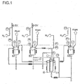
- the apparatus has 3 storage vessels B1, B2 with a usable volume of 2.5 liters each and B3 with a usable volume of 4 liters.
- B1 serves to take up liquid sulfur, B2 to take up sodium and B3 to take up the sulfur and formed polysulfide from B2.
- C1 is the electrolysis cell. Nitrogen can be introduced into the apparatus via valves at the points indicated by N 2 . There are safety valves at the points marked SV. At the marked points there are measuring instruments for the determination of flow rate (FI), pressure (PI), level (LI) and temperature (TI).
- FI flow rate
- PI pressure
- LI level
- TI temperature
- the containers have a quick release opening in the lid for filling solids.
- the electrolytic reactor C1 divided with a ceramic ion-conducting solid electrolyte (200 cm 2 , 2 mm thick) is connected by a solid casing with shut-off valves with these 3 storage vessels.
- Positively poled is the sulfur-carrying part of the cell and the lines and containers B1 and B3 connected there.
- Negatively polarized is the sodium leading part of the cell and the lines connected there and the container B2.
- sulfur was introduced as a powder with a conductive additive of 1% selenium and tetracyanoethylene and melted there under inert gas.
- the negatively polarized electrode space of the electrolysis reactor was filled with liquid sodium until it overflowed.
- the positively poled electrode space of the electrolysis reactor was filled to the overflow with liquid sulfur.
- the nitrogen stream flowing from B1 to B3 drove the sulfur (later polysulfide) from the reactor into vessel B3.
- the levels of the containers were then corrected by refilling.
- the containers B1 and B2 were filled to 80% before the start of the electrochemical power generation, the container B3 to 10%.
- the bottom valve of the container B1 (sulfur) was closed and opened via an orifice plate bottom valve of the container B2 (sodium) and closed the sodium valve in the bypass.
- the electrolysis device corresponded to the apparatus design of Example A) for power generation.
- the bottom valve of the container B1 (sulfur) was closed and the bottom valve of the container B2 (sodium), which led via an orifice, was opened and the sodium valve in the bypass closed.
- a 1000 MW storage power plant will be designed with storage capacity for 50 full load hours. This in Figure 2 The flow chart shows this power plant schematically.
- All product-leading apparatus and pipelines are kept at 300 ° C by means of electric booster heaters and a corresponding thermal insulation.
- the tanks are refueled from tankers with liquid sodium (B2) or liquid sulfur (B1).
- B2 liquid sodium
- B1 electrolysis reactor blocks
- C1 C2 and C3 with a rated electrical output of 334 MW each.
- These reactor blocks consist of modular ceramic reactors with ion-conducting solid-state electrolytes.
- a 1000 MW storage power plant has a total reactor volume of 5000 m 3 and an electrode surface totaling 500,000 m 2 .
- the individual reactors are supplied with sodium or sulfur via a potential-separated distribution system.
- the polysulfide formed in the reaction is collected isolated and fed to the tank farm B3.
- the differently polarized lines and parts of the apparatus are held electrically isolated by suitable electrical insulation.
- the reservoir BA is electrically separated by means of a potential separation of the cell.
- Positively poled is the sulfur-carrying part of the electrolysis reactors.
- Negatively poled is the sodium leading part of the electrolysis reactors.
- the system basically according to the structure according to 2.1) is used by supplying electricity in a place with excess energy for storage.
- the electrochemical reaction potential is maintained at 2.00 volts per single cell with a controlled addition of sulfur.
- electrical series and parallel circuit from a total voltage on the DC side of 1000V and a total flow per reactor block of 334 kA.
- the direct current is transformed into three-phase current.
- the three-phase current is then clamped to mains voltage with the three-phase transformers.
- the amount of DC currents is as large as in power generation.
- the charging voltage is about 0.2 higher than the discharge voltage of the power generation.
- the system is long-term stable and cycle-stable.
- the transport of the reactants makes sense.
- sodium and sulfur can be generated in locations of high energy availability and transported specifically to places with high energy requirements.
- the reactants can be generated by means of photovoltaics in North Africa and then shipped by sea transport in a deep-sea port.
- a transport distance of 3,000 km and with a specific oil consumption of a deep-sea tanker of 1.6 g heavy oil / t-freight / km a heavy oil consumption of 244 tons results for a load of 50,000 twd.
- a kinetic efficiency of the internal combustion engine of 25%, this corresponds to an energy consumption of 684 MWh.
Landscapes
- Engineering & Computer Science (AREA)
- Chemical & Material Sciences (AREA)
- General Chemical & Material Sciences (AREA)
- Manufacturing & Machinery (AREA)
- Chemical Kinetics & Catalysis (AREA)
- Electrochemistry (AREA)
- Sustainable Development (AREA)
- Life Sciences & Earth Sciences (AREA)
- Sustainable Energy (AREA)
- Power Engineering (AREA)
- Combustion & Propulsion (AREA)
- Mechanical Engineering (AREA)
- General Engineering & Computer Science (AREA)
- Secondary Cells (AREA)
- Electrolytic Production Of Metals (AREA)
- Battery Electrode And Active Subsutance (AREA)
- Hybrid Cells (AREA)
Priority Applications (1)
| Application Number | Priority Date | Filing Date | Title |
|---|---|---|---|
| EP10712053.7A EP2415113B1 (de) | 2009-04-01 | 2010-03-29 | Verfahren zur speicherung und transport elektrochemischer energie |
Applications Claiming Priority (3)
| Application Number | Priority Date | Filing Date | Title |
|---|---|---|---|
| EP09157056 | 2009-04-01 | ||
| PCT/EP2010/054123 WO2010112466A1 (de) | 2009-04-01 | 2010-03-29 | Verfahren zur speicherung und transport elektrochemischer energie |
| EP10712053.7A EP2415113B1 (de) | 2009-04-01 | 2010-03-29 | Verfahren zur speicherung und transport elektrochemischer energie |
Publications (2)
| Publication Number | Publication Date |
|---|---|
| EP2415113A1 EP2415113A1 (de) | 2012-02-08 |
| EP2415113B1 true EP2415113B1 (de) | 2015-11-11 |
Family
ID=42242414
Family Applications (1)
| Application Number | Title | Priority Date | Filing Date |
|---|---|---|---|
| EP10712053.7A Not-in-force EP2415113B1 (de) | 2009-04-01 | 2010-03-29 | Verfahren zur speicherung und transport elektrochemischer energie |
Country Status (9)
| Country | Link |
|---|---|
| US (1) | US9972857B2 (cg-RX-API-DMAC7.html) |
| EP (1) | EP2415113B1 (cg-RX-API-DMAC7.html) |
| JP (1) | JP5734273B2 (cg-RX-API-DMAC7.html) |
| KR (1) | KR101831911B1 (cg-RX-API-DMAC7.html) |
| CN (1) | CN102449838B (cg-RX-API-DMAC7.html) |
| AU (1) | AU2010230244B2 (cg-RX-API-DMAC7.html) |
| ES (1) | ES2559930T3 (cg-RX-API-DMAC7.html) |
| PT (1) | PT2415113E (cg-RX-API-DMAC7.html) |
| WO (1) | WO2010112466A1 (cg-RX-API-DMAC7.html) |
Families Citing this family (10)
| Publication number | Priority date | Publication date | Assignee | Title |
|---|---|---|---|---|
| US8679668B2 (en) | 2010-06-22 | 2014-03-25 | Basf Se | Industrial apparatus for the large-scale storage of electric energy |
| DE102011110843A1 (de) * | 2011-08-23 | 2013-02-28 | Johannes Daniel Werner | Speicherwerk für Elektroenergie auf Basis der Natrium-Schwefel-Zelle |
| CN102544612B (zh) * | 2012-02-17 | 2014-09-24 | 车国锋 | 电动汽车充电方法和充电系统 |
| US20130330634A1 (en) * | 2012-06-11 | 2013-12-12 | Basf Se | Electrode unit |
| DE102012013921B4 (de) | 2012-07-16 | 2014-09-04 | GroNaS GmbH | Bewehrte, Natriumionen leitende Festelektrolytmembranen und Verfahren zu ihrer Herstellung |
| US20140027300A1 (en) * | 2012-07-27 | 2014-01-30 | Basf Se | Process for preparing an alkali metal |
| KR101680696B1 (ko) | 2014-12-31 | 2016-12-12 | 주식회사 삼지에이 | 산업용 크린룸 설비(ICR, industrial clean room) 내의 헤파필터 교체 알림 시스템 |
| EP3217467A1 (de) * | 2016-03-08 | 2017-09-13 | Basf Se | Vorrichtung zur speicherung von elektrischer energie und verfahren zum betrieb der vorrichtung |
| CN112768791A (zh) * | 2021-01-27 | 2021-05-07 | 中国科学院上海硅酸盐研究所 | 一种液流型钠硫电池 |
| CN117154164B (zh) * | 2023-09-27 | 2024-03-22 | 中航国际科技成果转化基地(蚌埠)有限公司 | 一种液流电池组 |
Family Cites Families (20)
| Publication number | Priority date | Publication date | Assignee | Title |
|---|---|---|---|---|
| US3533848A (en) | 1967-04-20 | 1970-10-13 | Gen Electric | Sodium-sulfur fuel cell units |
| FR2305034A1 (fr) | 1975-03-17 | 1976-10-15 | Comp Generale Electricite | Batterie sodium-soufre, notamment pour traction electrique |
| US4038465A (en) | 1975-11-11 | 1977-07-26 | Ford Motor Company | Sodium sulfur battery or cell with external storage |
| US3994745A (en) * | 1976-01-30 | 1976-11-30 | Ford Motor Company | Secondary battery with separate charge and discharge zones |
| US4049885A (en) * | 1976-10-12 | 1977-09-20 | Electric Power Research Institute, Inc. | Construction for solid electrolyte in sodium/sulfur battery |
| IT1212303B (it) | 1978-07-10 | 1989-11-22 | Elche Ltd | Accumulatore redox. |
| JPS5978120A (ja) | 1982-10-28 | 1984-05-04 | Meiji Seika Kaisha Ltd | 抗ウイルス剤 |
| JPS59151777A (ja) * | 1983-02-18 | 1984-08-30 | Hitachi Ltd | ナトリウム−イオウ電池 |
| JPS6156291A (ja) * | 1984-08-25 | 1986-03-20 | Power Reactor & Nuclear Fuel Dev Corp | 液体ナトリウムの電気化学的精製方法 |
| US4895776A (en) * | 1987-03-12 | 1990-01-23 | Ceramatec, Inc. | Electrochemical cell utilizing selenium as an electrode-reactant |
| JPH0353464A (ja) * | 1989-07-21 | 1991-03-07 | Tokyo Electric Power Co Inc:The | ナトリウム―硫黄電池およびその製造法 |
| JP3054795B2 (ja) * | 1993-12-10 | 2000-06-19 | 株式会社日立製作所 | ナトリウム−硫黄電池用固体電解質及びそれを用いたナトリウム−硫黄電池の製造方法 |
| JP3266083B2 (ja) * | 1997-12-24 | 2002-03-18 | 株式会社日立製作所 | ナトリウム硫黄電池再生方法およびその装置 |
| JP2001118598A (ja) * | 1999-10-18 | 2001-04-27 | Mitsubishi Heavy Ind Ltd | ナトリウム−硫黄電池システム |
| JP4629839B2 (ja) | 2000-09-07 | 2011-02-09 | クラリオン株式会社 | 画像変換装置 |
| JP2002184456A (ja) | 2000-12-15 | 2002-06-28 | Mitsubishi Heavy Ind Ltd | ナトリウム硫黄電池 |
| JP2003221913A (ja) | 2002-01-31 | 2003-08-08 | Konoshima Chemical Co Ltd | 建築用化粧板材 |
| JP2003331913A (ja) * | 2002-05-13 | 2003-11-21 | Mitsubishi Heavy Ind Ltd | ナトリウム硫黄電池 |
| US20070054170A1 (en) * | 2005-09-02 | 2007-03-08 | Isenberg Arnold O | Oxygen ion conductors for electrochemical cells |
| CN201038266Y (zh) * | 2007-04-19 | 2008-03-19 | 陈会林 | 一种大功率钠硫动力电池 |
-
2010
- 2010-03-29 PT PT107120537T patent/PT2415113E/pt unknown
- 2010-03-29 WO PCT/EP2010/054123 patent/WO2010112466A1/de not_active Ceased
- 2010-03-29 ES ES10712053.7T patent/ES2559930T3/es active Active
- 2010-03-29 JP JP2012502622A patent/JP5734273B2/ja not_active Expired - Fee Related
- 2010-03-29 US US13/262,735 patent/US9972857B2/en not_active Expired - Fee Related
- 2010-03-29 KR KR1020117026080A patent/KR101831911B1/ko not_active Expired - Fee Related
- 2010-03-29 AU AU2010230244A patent/AU2010230244B2/en not_active Ceased
- 2010-03-29 EP EP10712053.7A patent/EP2415113B1/de not_active Not-in-force
- 2010-03-29 CN CN201080023453.6A patent/CN102449838B/zh not_active Expired - Fee Related
Also Published As
| Publication number | Publication date |
|---|---|
| KR20120016625A (ko) | 2012-02-24 |
| ES2559930T3 (es) | 2016-02-16 |
| KR101831911B1 (ko) | 2018-02-26 |
| JP2012523068A (ja) | 2012-09-27 |
| JP5734273B2 (ja) | 2015-06-17 |
| AU2010230244A1 (en) | 2011-11-10 |
| CN102449838A (zh) | 2012-05-09 |
| WO2010112466A1 (de) | 2010-10-07 |
| AU2010230244B2 (en) | 2016-02-25 |
| PT2415113E (pt) | 2016-03-17 |
| EP2415113A1 (de) | 2012-02-08 |
| US20120040262A1 (en) | 2012-02-16 |
| US9972857B2 (en) | 2018-05-15 |
| CN102449838B (zh) | 2015-01-07 |
Similar Documents
| Publication | Publication Date | Title |
|---|---|---|
| EP2415113B1 (de) | Verfahren zur speicherung und transport elektrochemischer energie | |
| EP2768043B1 (de) | Verbesserte technische Vorrichtung zum großtechnischen Speichern von elektrischer Energie | |
| CN104781981B (zh) | 用金属储存电能的电化学系统 | |
| US20120135282A1 (en) | Batteries for efficient energy extraction from a salinity difference | |
| WO2017153081A1 (de) | Verfahren und vorrichtung zur elektrochemischen nutzung von kohlenstoffdioxid | |
| EP3154112A1 (de) | Mobiler energieträger und energiespeicher | |
| EP3645454A1 (en) | Hydrogen generator | |
| JP2013028822A (ja) | アルカリ水電解装置およびアルカリ水電解方法 | |
| CN112501640A (zh) | 一种将硝酸盐废水转化为氨的电池系统 | |
| DE102018213018A1 (de) | Vorrichtung und Verfahren zur thermisch-elektrochemischen Energiespeicherung und Energiebereitstellung | |
| Ashurov et al. | Solving the problem of energy storage for solar photovoltaic plants | |
| KR20190033062A (ko) | 전해액 유통형 전지용 전해액 및 전해액 유통형 전지 시스템 | |
| US11101485B2 (en) | Flow battery | |
| EP2917959B1 (de) | Verfahren zur bereitstellung elektrischer energie für einen verbraucher | |
| EP3637510B1 (de) | Alkalibatterie mit keramischem festkörperelektrolyten | |
| Zhang et al. | Exploring multi-segment electrolyte design strategies for portable high-energy aqueous batteries | |
| SI25573A (sl) | Postopek za shranjevanje električne energije v trdni snovi | |
| DE102011102892A1 (de) | Hybrid aus Batterie und Kondensator zur reversiblen Speicherung elektrischer Energie mit hoher Energiedichte | |
| RU2540410C9 (ru) | Способ аккумулирования энергии | |
| Gandhi | Storage of electrical energy | |
| DE102017112515B4 (de) | Verfahren zum Betreiben eines Speichers für elektrische Energie und Vorrichtung zur Durchführung des Verfahrens | |
| Bockelmann | Investigation and prevention of anodic zinc passivation in alkaline zinc-air batteries | |
| CH706637A2 (de) | Taucherglocken-Elektrolyseur. | |
| DE102006011821A1 (de) | Brennstoffzelle für metallischen Brennstoff |
Legal Events
| Date | Code | Title | Description |
|---|---|---|---|
| PUAI | Public reference made under article 153(3) epc to a published international application that has entered the european phase |
Free format text: ORIGINAL CODE: 0009012 |
|
| 17P | Request for examination filed |
Effective date: 20111102 |
|
| AK | Designated contracting states |
Kind code of ref document: A1 Designated state(s): AT BE BG CH CY CZ DE DK EE ES FI FR GB GR HR HU IE IS IT LI LT LU LV MC MK MT NL NO PL PT RO SE SI SK SM TR |
|
| DAX | Request for extension of the european patent (deleted) | ||
| 17Q | First examination report despatched |
Effective date: 20130321 |
|
| GRAP | Despatch of communication of intention to grant a patent |
Free format text: ORIGINAL CODE: EPIDOSNIGR1 |
|
| INTG | Intention to grant announced |
Effective date: 20150616 |
|
| GRAS | Grant fee paid |
Free format text: ORIGINAL CODE: EPIDOSNIGR3 |
|
| GRAA | (expected) grant |
Free format text: ORIGINAL CODE: 0009210 |
|
| AK | Designated contracting states |
Kind code of ref document: B1 Designated state(s): AT BE BG CH CY CZ DE DK EE ES FI FR GB GR HR HU IE IS IT LI LT LU LV MC MK MT NL NO PL PT RO SE SI SK SM TR |
|
| REG | Reference to a national code |
Ref country code: GB Ref legal event code: FG4D Free format text: NOT ENGLISH |
|
| REG | Reference to a national code |
Ref country code: CH Ref legal event code: EP |
|
| REG | Reference to a national code |
Ref country code: IE Ref legal event code: FG4D Free format text: LANGUAGE OF EP DOCUMENT: GERMAN |
|
| REG | Reference to a national code |
Ref country code: AT Ref legal event code: REF Ref document number: 760852 Country of ref document: AT Kind code of ref document: T Effective date: 20151215 |
|
| REG | Reference to a national code |
Ref country code: DE Ref legal event code: R096 Ref document number: 502010010634 Country of ref document: DE |
|
| REG | Reference to a national code |
Ref country code: ES Ref legal event code: FG2A Ref document number: 2559930 Country of ref document: ES Kind code of ref document: T3 Effective date: 20160216 |
|
| REG | Reference to a national code |
Ref country code: LT Ref legal event code: MG4D |
|
| REG | Reference to a national code |
Ref country code: NL Ref legal event code: MP Effective date: 20160211 |
|
| REG | Reference to a national code |
Ref country code: PT Ref legal event code: SC4A Free format text: AVAILABILITY OF NATIONAL TRANSLATION Effective date: 20160208 |
|
| REG | Reference to a national code |
Ref country code: FR Ref legal event code: PLFP Year of fee payment: 7 |
|
| PG25 | Lapsed in a contracting state [announced via postgrant information from national office to epo] |
Ref country code: NO Free format text: LAPSE BECAUSE OF FAILURE TO SUBMIT A TRANSLATION OF THE DESCRIPTION OR TO PAY THE FEE WITHIN THE PRESCRIBED TIME-LIMIT Effective date: 20160211 Ref country code: HR Free format text: LAPSE BECAUSE OF FAILURE TO SUBMIT A TRANSLATION OF THE DESCRIPTION OR TO PAY THE FEE WITHIN THE PRESCRIBED TIME-LIMIT Effective date: 20151111 Ref country code: IS Free format text: LAPSE BECAUSE OF FAILURE TO SUBMIT A TRANSLATION OF THE DESCRIPTION OR TO PAY THE FEE WITHIN THE PRESCRIBED TIME-LIMIT Effective date: 20160311 Ref country code: NL Free format text: LAPSE BECAUSE OF FAILURE TO SUBMIT A TRANSLATION OF THE DESCRIPTION OR TO PAY THE FEE WITHIN THE PRESCRIBED TIME-LIMIT Effective date: 20151111 Ref country code: LT Free format text: LAPSE BECAUSE OF FAILURE TO SUBMIT A TRANSLATION OF THE DESCRIPTION OR TO PAY THE FEE WITHIN THE PRESCRIBED TIME-LIMIT Effective date: 20151111 |
|
| PG25 | Lapsed in a contracting state [announced via postgrant information from national office to epo] |
Ref country code: SE Free format text: LAPSE BECAUSE OF FAILURE TO SUBMIT A TRANSLATION OF THE DESCRIPTION OR TO PAY THE FEE WITHIN THE PRESCRIBED TIME-LIMIT Effective date: 20151111 Ref country code: LV Free format text: LAPSE BECAUSE OF FAILURE TO SUBMIT A TRANSLATION OF THE DESCRIPTION OR TO PAY THE FEE WITHIN THE PRESCRIBED TIME-LIMIT Effective date: 20151111 Ref country code: PL Free format text: LAPSE BECAUSE OF FAILURE TO SUBMIT A TRANSLATION OF THE DESCRIPTION OR TO PAY THE FEE WITHIN THE PRESCRIBED TIME-LIMIT Effective date: 20151111 Ref country code: FI Free format text: LAPSE BECAUSE OF FAILURE TO SUBMIT A TRANSLATION OF THE DESCRIPTION OR TO PAY THE FEE WITHIN THE PRESCRIBED TIME-LIMIT Effective date: 20151111 |
|
| REG | Reference to a national code |
Ref country code: GR Ref legal event code: EP Ref document number: 20160400098 Country of ref document: GR Effective date: 20160414 |
|
| PG25 | Lapsed in a contracting state [announced via postgrant information from national office to epo] |
Ref country code: CZ Free format text: LAPSE BECAUSE OF FAILURE TO SUBMIT A TRANSLATION OF THE DESCRIPTION OR TO PAY THE FEE WITHIN THE PRESCRIBED TIME-LIMIT Effective date: 20151111 |
|
| REG | Reference to a national code |
Ref country code: DE Ref legal event code: R097 Ref document number: 502010010634 Country of ref document: DE |
|
| PG25 | Lapsed in a contracting state [announced via postgrant information from national office to epo] |
Ref country code: SM Free format text: LAPSE BECAUSE OF FAILURE TO SUBMIT A TRANSLATION OF THE DESCRIPTION OR TO PAY THE FEE WITHIN THE PRESCRIBED TIME-LIMIT Effective date: 20151111 Ref country code: EE Free format text: LAPSE BECAUSE OF FAILURE TO SUBMIT A TRANSLATION OF THE DESCRIPTION OR TO PAY THE FEE WITHIN THE PRESCRIBED TIME-LIMIT Effective date: 20151111 Ref country code: SK Free format text: LAPSE BECAUSE OF FAILURE TO SUBMIT A TRANSLATION OF THE DESCRIPTION OR TO PAY THE FEE WITHIN THE PRESCRIBED TIME-LIMIT Effective date: 20151111 Ref country code: RO Free format text: LAPSE BECAUSE OF FAILURE TO SUBMIT A TRANSLATION OF THE DESCRIPTION OR TO PAY THE FEE WITHIN THE PRESCRIBED TIME-LIMIT Effective date: 20151111 Ref country code: DK Free format text: LAPSE BECAUSE OF FAILURE TO SUBMIT A TRANSLATION OF THE DESCRIPTION OR TO PAY THE FEE WITHIN THE PRESCRIBED TIME-LIMIT Effective date: 20151111 Ref country code: BE Free format text: LAPSE BECAUSE OF NON-PAYMENT OF DUE FEES Effective date: 20160331 |
|
| PLBE | No opposition filed within time limit |
Free format text: ORIGINAL CODE: 0009261 |
|
| STAA | Information on the status of an ep patent application or granted ep patent |
Free format text: STATUS: NO OPPOSITION FILED WITHIN TIME LIMIT |
|
| 26N | No opposition filed |
Effective date: 20160812 |
|
| PG25 | Lapsed in a contracting state [announced via postgrant information from national office to epo] |
Ref country code: MC Free format text: LAPSE BECAUSE OF FAILURE TO SUBMIT A TRANSLATION OF THE DESCRIPTION OR TO PAY THE FEE WITHIN THE PRESCRIBED TIME-LIMIT Effective date: 20151111 Ref country code: LU Free format text: LAPSE BECAUSE OF FAILURE TO SUBMIT A TRANSLATION OF THE DESCRIPTION OR TO PAY THE FEE WITHIN THE PRESCRIBED TIME-LIMIT Effective date: 20160329 |
|
| PG25 | Lapsed in a contracting state [announced via postgrant information from national office to epo] |
Ref country code: SI Free format text: LAPSE BECAUSE OF FAILURE TO SUBMIT A TRANSLATION OF THE DESCRIPTION OR TO PAY THE FEE WITHIN THE PRESCRIBED TIME-LIMIT Effective date: 20151111 |
|
| REG | Reference to a national code |
Ref country code: IE Ref legal event code: MM4A |
|
| PG25 | Lapsed in a contracting state [announced via postgrant information from national office to epo] |
Ref country code: IE Free format text: LAPSE BECAUSE OF NON-PAYMENT OF DUE FEES Effective date: 20160329 |
|
| REG | Reference to a national code |
Ref country code: GR Ref legal event code: ML Ref document number: 20160400098 Country of ref document: GR Effective date: 20161006 |
|
| PG25 | Lapsed in a contracting state [announced via postgrant information from national office to epo] |
Ref country code: PT Free format text: LAPSE BECAUSE OF NON-PAYMENT OF DUE FEES Effective date: 20161229 Ref country code: GR Free format text: LAPSE BECAUSE OF NON-PAYMENT OF DUE FEES Effective date: 20161006 |
|
| REG | Reference to a national code |
Ref country code: FR Ref legal event code: PLFP Year of fee payment: 8 |
|
| PG25 | Lapsed in a contracting state [announced via postgrant information from national office to epo] |
Ref country code: IT Free format text: LAPSE BECAUSE OF NON-PAYMENT OF DUE FEES Effective date: 20160329 |
|
| PG25 | Lapsed in a contracting state [announced via postgrant information from national office to epo] |
Ref country code: IT Free format text: LAPSE BECAUSE OF NON-PAYMENT OF DUE FEES Effective date: 20160329 Ref country code: MT Free format text: LAPSE BECAUSE OF FAILURE TO SUBMIT A TRANSLATION OF THE DESCRIPTION OR TO PAY THE FEE WITHIN THE PRESCRIBED TIME-LIMIT Effective date: 20151111 |
|
| PGRI | Patent reinstated in contracting state [announced from national office to epo] |
Ref country code: IT Effective date: 20170710 |
|
| REG | Reference to a national code |
Ref country code: FR Ref legal event code: PLFP Year of fee payment: 9 |
|
| PGFP | Annual fee paid to national office [announced via postgrant information from national office to epo] |
Ref country code: CH Payment date: 20180323 Year of fee payment: 9 Ref country code: GB Payment date: 20180329 Year of fee payment: 9 |
|
| PG25 | Lapsed in a contracting state [announced via postgrant information from national office to epo] |
Ref country code: CY Free format text: LAPSE BECAUSE OF FAILURE TO SUBMIT A TRANSLATION OF THE DESCRIPTION OR TO PAY THE FEE WITHIN THE PRESCRIBED TIME-LIMIT Effective date: 20151111 Ref country code: HU Free format text: LAPSE BECAUSE OF FAILURE TO SUBMIT A TRANSLATION OF THE DESCRIPTION OR TO PAY THE FEE WITHIN THE PRESCRIBED TIME-LIMIT; INVALID AB INITIO Effective date: 20100329 |
|
| PGFP | Annual fee paid to national office [announced via postgrant information from national office to epo] |
Ref country code: FR Payment date: 20180329 Year of fee payment: 9 Ref country code: AT Payment date: 20180328 Year of fee payment: 9 Ref country code: TR Payment date: 20180315 Year of fee payment: 9 |
|
| PG25 | Lapsed in a contracting state [announced via postgrant information from national office to epo] |
Ref country code: MK Free format text: LAPSE BECAUSE OF FAILURE TO SUBMIT A TRANSLATION OF THE DESCRIPTION OR TO PAY THE FEE WITHIN THE PRESCRIBED TIME-LIMIT Effective date: 20151111 |
|
| PG25 | Lapsed in a contracting state [announced via postgrant information from national office to epo] |
Ref country code: BG Free format text: LAPSE BECAUSE OF FAILURE TO SUBMIT A TRANSLATION OF THE DESCRIPTION OR TO PAY THE FEE WITHIN THE PRESCRIBED TIME-LIMIT Effective date: 20151111 |
|
| PGFP | Annual fee paid to national office [announced via postgrant information from national office to epo] |
Ref country code: ES Payment date: 20180423 Year of fee payment: 9 Ref country code: DE Payment date: 20180530 Year of fee payment: 9 |
|
| PGFP | Annual fee paid to national office [announced via postgrant information from national office to epo] |
Ref country code: IT Payment date: 20180323 Year of fee payment: 9 |
|
| REG | Reference to a national code |
Ref country code: DE Ref legal event code: R119 Ref document number: 502010010634 Country of ref document: DE |
|
| REG | Reference to a national code |
Ref country code: CH Ref legal event code: PL |
|
| REG | Reference to a national code |
Ref country code: AT Ref legal event code: MM01 Ref document number: 760852 Country of ref document: AT Kind code of ref document: T Effective date: 20190329 |
|
| GBPC | Gb: european patent ceased through non-payment of renewal fee |
Effective date: 20190329 |
|
| PG25 | Lapsed in a contracting state [announced via postgrant information from national office to epo] |
Ref country code: AT Free format text: LAPSE BECAUSE OF NON-PAYMENT OF DUE FEES Effective date: 20190329 Ref country code: GB Free format text: LAPSE BECAUSE OF NON-PAYMENT OF DUE FEES Effective date: 20190329 Ref country code: LI Free format text: LAPSE BECAUSE OF NON-PAYMENT OF DUE FEES Effective date: 20190331 Ref country code: DE Free format text: LAPSE BECAUSE OF NON-PAYMENT OF DUE FEES Effective date: 20191001 Ref country code: CH Free format text: LAPSE BECAUSE OF NON-PAYMENT OF DUE FEES Effective date: 20190331 |
|
| PG25 | Lapsed in a contracting state [announced via postgrant information from national office to epo] |
Ref country code: IT Free format text: LAPSE BECAUSE OF NON-PAYMENT OF DUE FEES Effective date: 20190329 Ref country code: FR Free format text: LAPSE BECAUSE OF NON-PAYMENT OF DUE FEES Effective date: 20190331 |
|
| REG | Reference to a national code |
Ref country code: ES Ref legal event code: FD2A Effective date: 20200729 |
|
| PG25 | Lapsed in a contracting state [announced via postgrant information from national office to epo] |
Ref country code: ES Free format text: LAPSE BECAUSE OF NON-PAYMENT OF DUE FEES Effective date: 20190330 |
|
| PG25 | Lapsed in a contracting state [announced via postgrant information from national office to epo] |
Ref country code: TR Free format text: LAPSE BECAUSE OF NON-PAYMENT OF DUE FEES Effective date: 20190329 |