EP2414079B1 - Alterungsstabiler katalysator zur oxidation von no zu no2 in abgasströmen - Google Patents
Alterungsstabiler katalysator zur oxidation von no zu no2 in abgasströmen Download PDFInfo
- Publication number
- EP2414079B1 EP2414079B1 EP10711666.7A EP10711666A EP2414079B1 EP 2414079 B1 EP2414079 B1 EP 2414079B1 EP 10711666 A EP10711666 A EP 10711666A EP 2414079 B1 EP2414079 B1 EP 2414079B1
- Authority
- EP
- European Patent Office
- Prior art keywords
- catalyst
- platinum
- zeolite
- catalyst according
- producing
- Prior art date
- Legal status (The legal status is an assumption and is not a legal conclusion. Google has not performed a legal analysis and makes no representation as to the accuracy of the status listed.)
- Not-in-force
Links
Images

Classifications
-
- B—PERFORMING OPERATIONS; TRANSPORTING
- B01—PHYSICAL OR CHEMICAL PROCESSES OR APPARATUS IN GENERAL
- B01J—CHEMICAL OR PHYSICAL PROCESSES, e.g. CATALYSIS OR COLLOID CHEMISTRY; THEIR RELEVANT APPARATUS
- B01J29/00—Catalysts comprising molecular sieves
- B01J29/04—Catalysts comprising molecular sieves having base-exchange properties, e.g. crystalline zeolites
- B01J29/06—Crystalline aluminosilicate zeolites; Isomorphous compounds thereof
- B01J29/70—Crystalline aluminosilicate zeolites; Isomorphous compounds thereof of types characterised by their specific structure not provided for in groups B01J29/08 - B01J29/65
- B01J29/72—Crystalline aluminosilicate zeolites; Isomorphous compounds thereof of types characterised by their specific structure not provided for in groups B01J29/08 - B01J29/65 containing iron group metals, noble metals or copper
- B01J29/74—Noble metals
- B01J29/7415—Zeolite Beta
-
- B—PERFORMING OPERATIONS; TRANSPORTING
- B01—PHYSICAL OR CHEMICAL PROCESSES OR APPARATUS IN GENERAL
- B01D—SEPARATION
- B01D53/00—Separation of gases or vapours; Recovering vapours of volatile solvents from gases; Chemical or biological purification of waste gases, e.g. engine exhaust gases, smoke, fumes, flue gases, aerosols
- B01D53/34—Chemical or biological purification of waste gases
- B01D53/92—Chemical or biological purification of waste gases of engine exhaust gases
- B01D53/94—Chemical or biological purification of waste gases of engine exhaust gases by catalytic processes
-
- B—PERFORMING OPERATIONS; TRANSPORTING
- B01—PHYSICAL OR CHEMICAL PROCESSES OR APPARATUS IN GENERAL
- B01D—SEPARATION
- B01D53/00—Separation of gases or vapours; Recovering vapours of volatile solvents from gases; Chemical or biological purification of waste gases, e.g. engine exhaust gases, smoke, fumes, flue gases, aerosols
- B01D53/34—Chemical or biological purification of waste gases
- B01D53/92—Chemical or biological purification of waste gases of engine exhaust gases
- B01D53/94—Chemical or biological purification of waste gases of engine exhaust gases by catalytic processes
- B01D53/944—Simultaneously removing carbon monoxide, hydrocarbons or carbon making use of oxidation catalysts
-
- B—PERFORMING OPERATIONS; TRANSPORTING
- B01—PHYSICAL OR CHEMICAL PROCESSES OR APPARATUS IN GENERAL
- B01D—SEPARATION
- B01D53/00—Separation of gases or vapours; Recovering vapours of volatile solvents from gases; Chemical or biological purification of waste gases, e.g. engine exhaust gases, smoke, fumes, flue gases, aerosols
- B01D53/34—Chemical or biological purification of waste gases
- B01D53/92—Chemical or biological purification of waste gases of engine exhaust gases
- B01D53/94—Chemical or biological purification of waste gases of engine exhaust gases by catalytic processes
- B01D53/9445—Simultaneously removing carbon monoxide, hydrocarbons or nitrogen oxides making use of three-way catalysts [TWC] or four-way-catalysts [FWC]
- B01D53/945—Simultaneously removing carbon monoxide, hydrocarbons or nitrogen oxides making use of three-way catalysts [TWC] or four-way-catalysts [FWC] characterised by a specific catalyst
-
- B—PERFORMING OPERATIONS; TRANSPORTING
- B01—PHYSICAL OR CHEMICAL PROCESSES OR APPARATUS IN GENERAL
- B01J—CHEMICAL OR PHYSICAL PROCESSES, e.g. CATALYSIS OR COLLOID CHEMISTRY; THEIR RELEVANT APPARATUS
- B01J29/00—Catalysts comprising molecular sieves
- B01J29/04—Catalysts comprising molecular sieves having base-exchange properties, e.g. crystalline zeolites
- B01J29/06—Crystalline aluminosilicate zeolites; Isomorphous compounds thereof
- B01J29/064—Crystalline aluminosilicate zeolites; Isomorphous compounds thereof containing iron group metals, noble metals or copper
- B01J29/068—Noble metals
-
- B—PERFORMING OPERATIONS; TRANSPORTING
- B01—PHYSICAL OR CHEMICAL PROCESSES OR APPARATUS IN GENERAL
- B01J—CHEMICAL OR PHYSICAL PROCESSES, e.g. CATALYSIS OR COLLOID CHEMISTRY; THEIR RELEVANT APPARATUS
- B01J29/00—Catalysts comprising molecular sieves
- B01J29/04—Catalysts comprising molecular sieves having base-exchange properties, e.g. crystalline zeolites
- B01J29/06—Crystalline aluminosilicate zeolites; Isomorphous compounds thereof
- B01J29/08—Crystalline aluminosilicate zeolites; Isomorphous compounds thereof of the faujasite type, e.g. type X or Y
- B01J29/10—Crystalline aluminosilicate zeolites; Isomorphous compounds thereof of the faujasite type, e.g. type X or Y containing iron group metals, noble metals or copper
- B01J29/12—Noble metals
-
- B—PERFORMING OPERATIONS; TRANSPORTING
- B01—PHYSICAL OR CHEMICAL PROCESSES OR APPARATUS IN GENERAL
- B01J—CHEMICAL OR PHYSICAL PROCESSES, e.g. CATALYSIS OR COLLOID CHEMISTRY; THEIR RELEVANT APPARATUS
- B01J29/00—Catalysts comprising molecular sieves
- B01J29/04—Catalysts comprising molecular sieves having base-exchange properties, e.g. crystalline zeolites
- B01J29/06—Crystalline aluminosilicate zeolites; Isomorphous compounds thereof
- B01J29/08—Crystalline aluminosilicate zeolites; Isomorphous compounds thereof of the faujasite type, e.g. type X or Y
- B01J29/10—Crystalline aluminosilicate zeolites; Isomorphous compounds thereof of the faujasite type, e.g. type X or Y containing iron group metals, noble metals or copper
- B01J29/12—Noble metals
- B01J29/123—X-type faujasite
-
- B—PERFORMING OPERATIONS; TRANSPORTING
- B01—PHYSICAL OR CHEMICAL PROCESSES OR APPARATUS IN GENERAL
- B01J—CHEMICAL OR PHYSICAL PROCESSES, e.g. CATALYSIS OR COLLOID CHEMISTRY; THEIR RELEVANT APPARATUS
- B01J29/00—Catalysts comprising molecular sieves
- B01J29/04—Catalysts comprising molecular sieves having base-exchange properties, e.g. crystalline zeolites
- B01J29/06—Crystalline aluminosilicate zeolites; Isomorphous compounds thereof
- B01J29/08—Crystalline aluminosilicate zeolites; Isomorphous compounds thereof of the faujasite type, e.g. type X or Y
- B01J29/10—Crystalline aluminosilicate zeolites; Isomorphous compounds thereof of the faujasite type, e.g. type X or Y containing iron group metals, noble metals or copper
- B01J29/12—Noble metals
- B01J29/126—Y-type faujasite
-
- B—PERFORMING OPERATIONS; TRANSPORTING
- B01—PHYSICAL OR CHEMICAL PROCESSES OR APPARATUS IN GENERAL
- B01J—CHEMICAL OR PHYSICAL PROCESSES, e.g. CATALYSIS OR COLLOID CHEMISTRY; THEIR RELEVANT APPARATUS
- B01J29/00—Catalysts comprising molecular sieves
- B01J29/04—Catalysts comprising molecular sieves having base-exchange properties, e.g. crystalline zeolites
- B01J29/06—Crystalline aluminosilicate zeolites; Isomorphous compounds thereof
- B01J29/70—Crystalline aluminosilicate zeolites; Isomorphous compounds thereof of types characterised by their specific structure not provided for in groups B01J29/08 - B01J29/65
- B01J29/72—Crystalline aluminosilicate zeolites; Isomorphous compounds thereof of types characterised by their specific structure not provided for in groups B01J29/08 - B01J29/65 containing iron group metals, noble metals or copper
- B01J29/74—Noble metals
-
- B—PERFORMING OPERATIONS; TRANSPORTING
- B01—PHYSICAL OR CHEMICAL PROCESSES OR APPARATUS IN GENERAL
- B01J—CHEMICAL OR PHYSICAL PROCESSES, e.g. CATALYSIS OR COLLOID CHEMISTRY; THEIR RELEVANT APPARATUS
- B01J29/00—Catalysts comprising molecular sieves
- B01J29/04—Catalysts comprising molecular sieves having base-exchange properties, e.g. crystalline zeolites
- B01J29/06—Crystalline aluminosilicate zeolites; Isomorphous compounds thereof
- B01J29/70—Crystalline aluminosilicate zeolites; Isomorphous compounds thereof of types characterised by their specific structure not provided for in groups B01J29/08 - B01J29/65
- B01J29/72—Crystalline aluminosilicate zeolites; Isomorphous compounds thereof of types characterised by their specific structure not provided for in groups B01J29/08 - B01J29/65 containing iron group metals, noble metals or copper
- B01J29/74—Noble metals
- B01J29/743—CHA-type, e.g. Chabazite, LZ-218
-
- B—PERFORMING OPERATIONS; TRANSPORTING
- B01—PHYSICAL OR CHEMICAL PROCESSES OR APPARATUS IN GENERAL
- B01J—CHEMICAL OR PHYSICAL PROCESSES, e.g. CATALYSIS OR COLLOID CHEMISTRY; THEIR RELEVANT APPARATUS
- B01J29/00—Catalysts comprising molecular sieves
- B01J29/04—Catalysts comprising molecular sieves having base-exchange properties, e.g. crystalline zeolites
- B01J29/06—Crystalline aluminosilicate zeolites; Isomorphous compounds thereof
- B01J29/70—Crystalline aluminosilicate zeolites; Isomorphous compounds thereof of types characterised by their specific structure not provided for in groups B01J29/08 - B01J29/65
- B01J29/72—Crystalline aluminosilicate zeolites; Isomorphous compounds thereof of types characterised by their specific structure not provided for in groups B01J29/08 - B01J29/65 containing iron group metals, noble metals or copper
- B01J29/74—Noble metals
- B01J29/7446—EUO-type, e.g. EU-1, TPZ-3 or ZSM-50
-
- B—PERFORMING OPERATIONS; TRANSPORTING
- B01—PHYSICAL OR CHEMICAL PROCESSES OR APPARATUS IN GENERAL
- B01J—CHEMICAL OR PHYSICAL PROCESSES, e.g. CATALYSIS OR COLLOID CHEMISTRY; THEIR RELEVANT APPARATUS
- B01J29/00—Catalysts comprising molecular sieves
- B01J29/04—Catalysts comprising molecular sieves having base-exchange properties, e.g. crystalline zeolites
- B01J29/06—Crystalline aluminosilicate zeolites; Isomorphous compounds thereof
- B01J29/70—Crystalline aluminosilicate zeolites; Isomorphous compounds thereof of types characterised by their specific structure not provided for in groups B01J29/08 - B01J29/65
- B01J29/72—Crystalline aluminosilicate zeolites; Isomorphous compounds thereof of types characterised by their specific structure not provided for in groups B01J29/08 - B01J29/65 containing iron group metals, noble metals or copper
- B01J29/74—Noble metals
- B01J29/7469—MTW-type, e.g. ZSM-12, NU-13, TPZ-12 or Theta-3
-
- B—PERFORMING OPERATIONS; TRANSPORTING
- B01—PHYSICAL OR CHEMICAL PROCESSES OR APPARATUS IN GENERAL
- B01J—CHEMICAL OR PHYSICAL PROCESSES, e.g. CATALYSIS OR COLLOID CHEMISTRY; THEIR RELEVANT APPARATUS
- B01J29/00—Catalysts comprising molecular sieves
- B01J29/04—Catalysts comprising molecular sieves having base-exchange properties, e.g. crystalline zeolites
- B01J29/06—Crystalline aluminosilicate zeolites; Isomorphous compounds thereof
- B01J29/70—Crystalline aluminosilicate zeolites; Isomorphous compounds thereof of types characterised by their specific structure not provided for in groups B01J29/08 - B01J29/65
- B01J29/72—Crystalline aluminosilicate zeolites; Isomorphous compounds thereof of types characterised by their specific structure not provided for in groups B01J29/08 - B01J29/65 containing iron group metals, noble metals or copper
- B01J29/74—Noble metals
- B01J29/7484—TON-type, e.g. Theta-1, ISI-1, KZ-2, NU-10 or ZSM-22
-
- B—PERFORMING OPERATIONS; TRANSPORTING
- B01—PHYSICAL OR CHEMICAL PROCESSES OR APPARATUS IN GENERAL
- B01J—CHEMICAL OR PHYSICAL PROCESSES, e.g. CATALYSIS OR COLLOID CHEMISTRY; THEIR RELEVANT APPARATUS
- B01J37/00—Processes, in general, for preparing catalysts; Processes, in general, for activation of catalysts
- B01J37/02—Impregnation, coating or precipitation
-
- B—PERFORMING OPERATIONS; TRANSPORTING
- B01—PHYSICAL OR CHEMICAL PROCESSES OR APPARATUS IN GENERAL
- B01J—CHEMICAL OR PHYSICAL PROCESSES, e.g. CATALYSIS OR COLLOID CHEMISTRY; THEIR RELEVANT APPARATUS
- B01J37/00—Processes, in general, for preparing catalysts; Processes, in general, for activation of catalysts
- B01J37/02—Impregnation, coating or precipitation
- B01J37/0201—Impregnation
-
- B—PERFORMING OPERATIONS; TRANSPORTING
- B01—PHYSICAL OR CHEMICAL PROCESSES OR APPARATUS IN GENERAL
- B01J—CHEMICAL OR PHYSICAL PROCESSES, e.g. CATALYSIS OR COLLOID CHEMISTRY; THEIR RELEVANT APPARATUS
- B01J37/00—Processes, in general, for preparing catalysts; Processes, in general, for activation of catalysts
- B01J37/02—Impregnation, coating or precipitation
- B01J37/0201—Impregnation
- B01J37/0203—Impregnation the impregnation liquid containing organic compounds
-
- B—PERFORMING OPERATIONS; TRANSPORTING
- B01—PHYSICAL OR CHEMICAL PROCESSES OR APPARATUS IN GENERAL
- B01J—CHEMICAL OR PHYSICAL PROCESSES, e.g. CATALYSIS OR COLLOID CHEMISTRY; THEIR RELEVANT APPARATUS
- B01J37/00—Processes, in general, for preparing catalysts; Processes, in general, for activation of catalysts
- B01J37/08—Heat treatment
-
- B—PERFORMING OPERATIONS; TRANSPORTING
- B01—PHYSICAL OR CHEMICAL PROCESSES OR APPARATUS IN GENERAL
- B01J—CHEMICAL OR PHYSICAL PROCESSES, e.g. CATALYSIS OR COLLOID CHEMISTRY; THEIR RELEVANT APPARATUS
- B01J37/00—Processes, in general, for preparing catalysts; Processes, in general, for activation of catalysts
- B01J37/16—Reducing
-
- B—PERFORMING OPERATIONS; TRANSPORTING
- B01—PHYSICAL OR CHEMICAL PROCESSES OR APPARATUS IN GENERAL
- B01D—SEPARATION
- B01D2255/00—Catalysts
- B01D2255/10—Noble metals or compounds thereof
- B01D2255/102—Platinum group metals
- B01D2255/1021—Platinum
-
- B—PERFORMING OPERATIONS; TRANSPORTING
- B01—PHYSICAL OR CHEMICAL PROCESSES OR APPARATUS IN GENERAL
- B01D—SEPARATION
- B01D2255/00—Catalysts
- B01D2255/50—Zeolites
-
- B—PERFORMING OPERATIONS; TRANSPORTING
- B01—PHYSICAL OR CHEMICAL PROCESSES OR APPARATUS IN GENERAL
- B01D—SEPARATION
- B01D2258/00—Sources of waste gases
- B01D2258/01—Engine exhaust gases
- B01D2258/012—Diesel engines and lean burn gasoline engines
-
- B—PERFORMING OPERATIONS; TRANSPORTING
- B01—PHYSICAL OR CHEMICAL PROCESSES OR APPARATUS IN GENERAL
- B01J—CHEMICAL OR PHYSICAL PROCESSES, e.g. CATALYSIS OR COLLOID CHEMISTRY; THEIR RELEVANT APPARATUS
- B01J2229/00—Aspects of molecular sieve catalysts not covered by B01J29/00
- B01J2229/10—After treatment, characterised by the effect to be obtained
- B01J2229/18—After treatment, characterised by the effect to be obtained to introduce other elements into or onto the molecular sieve itself
- B01J2229/186—After treatment, characterised by the effect to be obtained to introduce other elements into or onto the molecular sieve itself not in framework positions
-
- B—PERFORMING OPERATIONS; TRANSPORTING
- B01—PHYSICAL OR CHEMICAL PROCESSES OR APPARATUS IN GENERAL
- B01J—CHEMICAL OR PHYSICAL PROCESSES, e.g. CATALYSIS OR COLLOID CHEMISTRY; THEIR RELEVANT APPARATUS
- B01J35/00—Catalysts, in general, characterised by their form or physical properties
- B01J35/50—Catalysts, in general, characterised by their form or physical properties characterised by their shape or configuration
- B01J35/56—Foraminous structures having flow-through passages or channels, e.g. grids or three-dimensional [3D] monoliths
-
- B—PERFORMING OPERATIONS; TRANSPORTING
- B01—PHYSICAL OR CHEMICAL PROCESSES OR APPARATUS IN GENERAL
- B01J—CHEMICAL OR PHYSICAL PROCESSES, e.g. CATALYSIS OR COLLOID CHEMISTRY; THEIR RELEVANT APPARATUS
- B01J37/00—Processes, in general, for preparing catalysts; Processes, in general, for activation of catalysts
- B01J37/02—Impregnation, coating or precipitation
- B01J37/024—Multiple impregnation or coating
- B01J37/0246—Coatings comprising a zeolite
-
- B—PERFORMING OPERATIONS; TRANSPORTING
- B01—PHYSICAL OR CHEMICAL PROCESSES OR APPARATUS IN GENERAL
- B01J—CHEMICAL OR PHYSICAL PROCESSES, e.g. CATALYSIS OR COLLOID CHEMISTRY; THEIR RELEVANT APPARATUS
- B01J37/00—Processes, in general, for preparing catalysts; Processes, in general, for activation of catalysts
- B01J37/16—Reducing
- B01J37/18—Reducing with gases containing free hydrogen
-
- Y—GENERAL TAGGING OF NEW TECHNOLOGICAL DEVELOPMENTS; GENERAL TAGGING OF CROSS-SECTIONAL TECHNOLOGIES SPANNING OVER SEVERAL SECTIONS OF THE IPC; TECHNICAL SUBJECTS COVERED BY FORMER USPC CROSS-REFERENCE ART COLLECTIONS [XRACs] AND DIGESTS
- Y02—TECHNOLOGIES OR APPLICATIONS FOR MITIGATION OR ADAPTATION AGAINST CLIMATE CHANGE
- Y02T—CLIMATE CHANGE MITIGATION TECHNOLOGIES RELATED TO TRANSPORTATION
- Y02T10/00—Road transport of goods or passengers
- Y02T10/10—Internal combustion engine [ICE] based vehicles
- Y02T10/12—Improving ICE efficiencies
Definitions
- the present invention relates to a process for the preparation of a platinum-containing catalyst according to the invention, to the platinum-containing catalyst according to the invention and to the use of the platinum-containing catalyst as oxidation catalyst and hydrocarbon reservoir.
- the exhaust gas of diesel engines has carbon monoxide, unburned hydrocarbons, nitrogen oxides and soot particles as air pollutants.
- the unburned hydrocarbons include paraffins, olefins, aldehydes and aromatics.
- DOC Diesel Oxidation Catalyst
- the skilled person understands a catalyst which preferably performs a hydrocarbon storage function in the cold start and oxidizes unburned hydrocarbons in normal operation.
- the treatment of the exhaust gases of diesel engines with catalytic converters requires conceptual changes to the catalyst materials, since a diesel engine is always operated in excess of oxygen, unlike a gasoline engine and thus the catalyst is never exposed to reductive conditions.
- Particulate filters are used to filter soot particles from the exhaust gas of internal combustion engines, especially diesel engines, and thus to reduce their emission into the atmosphere.
- various filter concepts such.
- wall-flow filter or filters made of ceramic or metallic foams for use.
- the real difficulty is not in the filtration of the soot particles, but in the regeneration of the filter used. Carbon black burns spontaneously depending on the operational composition of the particles only at temperatures between 500 ° C and 700 ° C.
- Newer generation diesel vehicles are currently equipped with a unit downstream of the diesel particulate filter that can accomplish a selective catalytic reduction of nitrogen oxides using a so-called SCR catalyst.
- SCR selective catalytic reduction
- NO x nitrogen oxides
- NH 3 ammonia
- NO 2 facilitates the regeneration of the subsequent diesel particulate filter, ie the Rußabbrand (see, for example J. Choo et al., Science of the total environment (2008) 396-401 ; M. Jeguirim et al. Applied Catalysis B: Environmental, 76 (2007), 235-240 or K. Yamamoto et al., Proceedings of the Combustion Institute, 32 (1) (2009), 1965-1972 ).
- SCR selective catalytic reduction
- catalysts are required which have a lower tendency to age under the operating conditions of the diesel exhaust aftertreatment than has hitherto been possible in the prior art.
- DOC catalysts In addition to Pt-based catalysts, catalysts which contain both Pt and Pd are known in the prior art. Furthermore, DOC catalysts often contain zeolites, which serve to store the hydrocarbons in the cold state (cold start trap), so that the cold start emissions of hydrocarbons are reduced.
- a typical DOC is for example in EP 800 856 A2 disclosed. It contains a high noble metal concentration with 3 to 4 g Pt / l catalyst volume. However, to achieve the lowest possible light-off temperature for CO and hydrocarbon, most of the platinum is deposited on an amorphous Al / Si mixed oxide and only a small portion on the zeolite. According to the prior art, it has hitherto not been possible to distribute a very high platinum concentration so homogeneously in the zeolite that it still has a good platinum dispersion even after a higher temperature load. The high platinum amount or dispersion causes sufficient stability, which is why in the prior art, the high amount of platinum was introduced into an Al / Si mixed oxide and not in the zeolites.
- the patent application US2006 / 0035780 A1 discloses a diesel oxidation catalyst comprising a honeycomb body coated with a mixture of clay, refractory oxide and a zeolite. The coated substrate is then loaded with a noble metal catalyst and a sulfur oxidation suppressant.
- the clay is an acid activated bentonite
- the refractory oxide is zirconia or titania
- the zeolite is zeolite beta, Y zeolite, ZSM-5 or mordenite
- the noble metal catalyst is preferably platinum and the sulfur oxidation suppression agent is vanadium, vanadium oxide or a Combination of both.
- Platinum-containing zeolites are known in the art. For example, zeolites with very low platinum contents ( ⁇ 1%) are used as catalysts in the refinery sector, e.g. for cyclization, aromatization, and cracking reactions. In contrast to the conditions prevailing in a diesel exhaust gas, the reactions just mentioned take place under reductive conditions (i.e., hydrocarbon surplus) and therefore require very little precious metal content.
- the publication WO 2009/138204 A2 discloses a process for preparing a precursor of a supported platinum catalyst.
- a method is proposed, comprising the steps of: a) impregnating an open-pore carrier material with platinum sulphite acid, b) calcining the impregnated zeolite material under an inert gas.
- DOC catalysts with improved stability are also usually provided by mixed Pt / Pd catalysts.
- Pt / Pd catalysts with a high Pt content (6: 1) show good thermal aging stability.
- the disadvantage is that the NO to NO 2 oxidation is worse with increasing Pd contents.
- the Pt / Pd catalysts are significantly less resistant to sulfur (see, for example, FIG. International Forum Emissions and Particle Emissions, 19 and 20 February 2008, Ludwigsburg, page 126 to 144 ).
- Such catalysts usually can not be thermally regenerated after sulfur poisoning, but still lose activity when thermally stressed after poisoning, ie, aged.
- the object of the present invention was therefore to provide a process for the preparation of a catalyst, in particular a diesel oxidation catalyst, which has a low tendency to age and high activity.
- the calcination of the impregnated zeolite should be carried out in a protective gas atmosphere, preferably an argon atmosphere or a nitrogen atmosphere is used. Particularly preferred is an argon atmosphere.
- the calcining of the impregnated zeolite is preferably carried out at a temperature of 600 to 900 ° C, more preferably> 750 to 850 ° C, more preferably> 750 to 830 ° C, in particular at about 800 ° C.
- Calcining produces a platinum precursor compound which, if necessary, is preferably reduced following calcining. In principle, however, a reduction can already take place during the calcination, in which case, however, a reducing atmosphere would have to be used instead of the inert gas atmosphere.
- a reduction which can be carried out after calcination is preferably carried out from a mixture of a reducing gas (hydrogen, carbon monoxide, ethene, a methanol, ethanol, etc.) and an inert gas.
- a reducing gas hydrogen, carbon monoxide, ethene, a methanol, ethanol, etc.
- inert gases are, for example, argon, helium, neon and the like.
- the inert gas in the reduction step is to be understood as a carrier gas, hydrogen or another reductive gas preferably being in a concentration of 1 to 10% by volume, more preferably 3 to 7% by volume, particularly preferably about 5% by volume, based on the total volume of reducing gas and inert gas.
- the reduction is usually carried out until complete or near completion of the platinum precursor compound has occurred.
- the reduction is preferably carried out over a period of 3 to 7 hours, more preferably 4 to 6 hours, particularly preferably about 5 hours.
- the reduction is preferably carried out at elevated temperatures.
- the reduction is carried out at a temperature of 200 to 500 ° C, more preferably 250 to 350 ° C, most preferably about 300 ° C.
- the catalyst is usually placed in a catalyst bed while flowing through the reducing agent.
- the catalyst can be covered with the reducing gas and advantageously brought to an elevated temperature.
- the increase in the temperature can be effected, for example, by heating the catalyst bed. It is also possible that the reducing gas is already heated in advance, for example by the gas supply line is heated, in which case the heated reducing gas is passed over the catalyst to be reduced.
- the impregnation of the zeolite with the platinum sulphite solution can be carried out by a dip impregnation, spray impregnation or incipient wetness method.
- the impregnation is done by an incipient wetness method, although according to the prior art usually in this impregnation method only a small part of the metal clusters migrate into the pores and a considerable part remains on the outer zeolite surface.
- the catalyst thus prepared has an increased sulfur resistance than already known systems.
- the catalytic activity of the thermally aged catalyst according to the invention is not changed by sulfur poisoning and subsequent high-temperature desulfurization.
- the catalyst developed shows a comparable aging behavior with respect to the oxidation of carbon monoxide as existing Pt-based catalysts, it has surprisingly been found that it has a significantly better stability with regard to the oxidation of NO.
- Another advantage of the prior art catalyst over that of the prior art is that the noble metal is supported on only one component, the zeolite, and not, as with other catalysts, on a mixture of zeolite and additional oxidic supports.
- the increased zeolite content also significantly increases the storage capacity for hydrocarbons (see, for example EP 691 883 B1 . US 5,804,155 and EP 830 301 ).
- the storage capacity is of great importance if the catalytic converter has not yet reached the required operating temperature and the resulting exhaust gases can not yet burn.
- zeolite is used in the context of the present invention as defined by the International Mineralical Association ( DS Coombs et al., Canadian Mineralogist, 35, 1979, 1571 ) a crystalline substance from the group of aluminum silicates having a spatial network structure of the general formula M x / n [(AlO 2 ) x (SiO 2 ) y ] x (H 2 O) z understood that consist of SiO 4 / AlO 4 tetrahedra, which are linked by common oxygen atoms to a regular three-dimensional network.
- the zeolite is becoming increasingly thermally unstable.
- the zeolite structure contains voids, channels that are characteristic of each zeolite.
- the zeolites are classified into different structures according to their topology.
- the zeolite framework contains open cavities in the form of channels and cages, usually containing water molecules and cages additional framework cations are occupied, which can be replaced.
- An aluminum atom has an excess negative charge which is compensated by these cations.
- the interior of the pore system represents the catalytically active surface. The more aluminum and the less silicon a zeolite contains, the denser the negative charge in its lattice and the more polar its internal surface.
- the pore size and structure in addition to the parameters in the preparation, ie use or type of templates, pH, pressure, temperature, presence of seed crystals, determined by the Si / Al ratio (modulus), which accounts for the majority of the catalytic character of a Make up zeolites.
- the zeolite of the present invention contains at least 2 wt% platinum, preferably at least 3 wt%, most preferably 3.5 or more wt% platinum, with at least 90% of the platinum in the pores of the zeolite, more preferably at least 95%, particularly preferably at least 99%.
- the zeolite is selected from the groups consisting of the types AEL, BEA, CHA, EUO, FAU, FER, KFI, LTA, LTL, MAZ, MOR, MEL, MTW, LEV, OFF, TON, and MFI.
- the BEA structure is particularly preferred.
- the zeolite has a SiO 2 / Al 2 O 3 modulus of from 5 to 300, preferably from 10 to 200, more preferably from 15 to 100.
- the stretching vibration is present even after poisoning with adamantanecarbonitrile.
- Adamantanecarbonitrile is a sterically demanding molecule, which due to its size can not penetrate into the pore system of the zeolite. Due to the adsorption of adamantanecarbonitrile, therefore, only Pt clusters on the outer surface of the poisoned. If CO is adsorbed following this poisoning, it can only bind to the non-poisoned Pt clusters in the interior of the zeolite.
- the zeolite in the catalyst according to the invention is also free in the X-ray diffractogram (XRD) from Pt reflections. This also shows that the platinum sits in the pores of the zeolite.
- XRD X-ray diffractogram
- Another object of the invention is the use of the catalyst according to the invention as an oxidation catalyst and hydrocarbon storage.
- Zeolites are known as hydrocarbon reservoirs.
- it in combination with the high platinum dispersion in the pores of the zeolite, it is also excellently suitable as an oxidation catalyst with a corresponding cumulative hydrocarbon storage function.
- platinum is applied only to a zeolite and not, as known in the art, to other metal oxides, results in a simple catalyst system that can be produced inexpensively.
- the zeolite can advantageously be processed into a washcoat and applied correspondingly to a catalyst carrier body. How such a washcoat can be made is known to the person skilled in the art. The necessary coating techniques for coating a catalyst carrier body are also known to the person skilled in the art.
- the impregnated and dried zeolite is processed to an aqueous coating dispersion.
- This dispersion may contain a binder, e.g. Silica sol, to be added.
- the viscosity of the dispersion can be adjusted by its own additives, so that it is possible to apply the required amount of coating in a single operation on the walls of the flow channels. If this is not possible, then the coating can be repeated several times, wherein the freshly applied coating is fixed in each case by an intermediate drying and calcined as needed.
- a metallic or ceramic monolith a nonwoven or a metal foam may be used.
- Other known in the prior art catalyst shaped body or catalyst carrier body are suitable according to the invention.
- a metallic or ceramic monolith having a plurality of parallel passage openings, which are provided with the Washcoatbe slaughterung.
- the carrier body preferably has passage openings with a round, triangular, quadrangular or polygonal cross section.
- the carrier is designed as a monolithic honeycomb body.
- Metallic honeycomb bodies are often formed from metal sheets or metal foils.
- the honeycomb bodies are produced for example by alternating arrangement of layers of structured sheets or films.
- these arrangements consist of a position of a smooth sheet alternating with a corrugated sheet, wherein the corrugation, for example, sinusoidal, trapezoidal, omega-shaped or may be formed zigzag.
- Corresponding metallic honeycomb bodies and processes for their preparation are described, for example, in US Pat EP 0 049 489 A1 or the DE 28 56 030 A1 described.
- metallic honeycomb bodies In the area of the catalyst carrier bodies, metallic honeycomb bodies have the advantage that they heat up more quickly and thus generally show better catalyst response on the basis of metallic substrates in cold start conditions.
- the honeycomb body preferably has a cell density of 30 to 1500 cpsi, particularly preferably 200 to 600 cpsi, in particular about 400 cpsi.
- the catalyst support body, to which the zeolite may be applied may be formed of any metal or metal alloy, and e.g. B. by extrusion or by winding or stacking or folding of metal foils.
- metal or metal alloy e.g. B. by extrusion or by winding or stacking or folding of metal foils.
- Known in the field of emission control are temperature-resistant alloys with the main components iron, chromium and aluminum.
- Preferred for the catalyst according to the invention are freely permeable monolithic catalyst carrier bodies with or without inner leading edges for the turbulence of the exhaust gas or metal foams which have a large inner surface and to which the catalyst according to the invention adheres very well.
- catalyst carrier bodies with slots, perforations, perforations and embossments can also be used in the metal foil.
- catalyst carrier bodies made of ceramic material can be used.
- the ceramic material is an inert, low surface area material such as cordierite, mullite, aluminum titanate or ⁇ -alumina.
- the catalyst support used may also consist of high surface area support material such as ⁇ -alumina.
- a metal foam for example a metallic open-pore foam material
- a metal foam for example a metallic open-pore foam material
- the term "metallic open-pore foam material” is to be understood as meaning a foam material made of any desired metal or alloy, which may optionally also contain additives and which has a multiplicity of pores which are conductively connected to one another such that For example, a gas can be passed through the foam material.
- Metallic open cell foam materials have a very low density due to the pores and voids, but have considerable rigidity and strength.
- the production of metal foams for example, by means of a metal powder and a metal hydride. Both powders are usually mixed together and then compacted by hot pressing or extrusion to a molding material. The molding material is then heated to a temperature above the melting point of the metals. The metal hydride releases hydrogen gas and foams the mixture.
- metal foams for example, by blowing gas into a molten metal that has been previously made foamable by adding solid ingredients.
- aluminum alloys for example, 10 to 20% by volume of silicon carbide or aluminum oxide is added for stabilization.
- open-pore metallic foam structures with a Make pore diameters from 10 ppi to about 50 ppi using special investment casting techniques.
- the carrier can in principle also be extruded and injection-molded. Again, metallic and ceramic materials are possible, in the case of ceramic materials, for example, form aids are added and, for example, binders and other additives. Extruded supports can take any geometry, preferably those mentioned above.
- the catalyst according to the invention is prepared according to the following procedure:
- the water uptake of a mixed oxide of alumina and silica was determined. It was 53.86%. 110.4 g of a solution of ethanolammonium hexahydroxoplatinate (13.59% Pt content) was made up to 161.6 ml (destilled with H 2 O). 300 g of the siralox powder were impregnated in a planetary mixer with this solution. The wet powder was oven dried at 80 ° C for 3 h and then calcined at 550 ° C for 3 h.
- the water uptake of a mixed oxide of alumina and silica was determined. It was 151%. 67.39 g of a solution of ethanolammonium hexahydroxoplatinate (13.85% Pt content) was made up with 58 ml of distilled water. This solution was used to impregnate 186 g of the siralox powder in a planetary mixer in a first step. Then, 17.34 g of a palladium nitrate solution was diluted with 58 ml of water, and further added dropwise as an impregnating solution to the wet powder in the planetary mixer in the next step. The wet powder was oven dried at 80 ° C for 3 h and then calcined at 550 ° C for 3 h. The powder contained 7% total precious metal content.
- the water uptake of a mixed oxide of alumina and silica was determined. It was 151%. 73.6 of a solution of ethanolammonium hexahydroxoplatinate (13.59% Pt content) was made up to 181 ml with distilled water. 200 g of the siralox powder was impregnated in a planetary mixer with this solution. The wet powder was oven dried at 80 ° C for 3 h and then calcined at 550 ° C for 3 h.
- the catalyst honeycomb was installed with a ceramic fiber mat in a quartz glass tube.
- the gas stream was electrically heated in front of the catalyst.
- the catalyst was operated at 390 ° C for only 30 minutes under these gas conditions and then cooled in 20 ° C increments. Each temperature was maintained for 8 minutes and the product composition determined between 7 and 8 minutes. Below 250 ° C, the cooling was carried out in 5 ° C steps in order to specifically determine the CO light-off temperature (50% CO conversion) more accurately.
- the catalyst was traversed with air with 10% steam at a space velocity of 5000 h -1 and heated under these gas conditions to 750 ° C (measured in monolith) within 2 h. Under these conditions, the catalyst was aged for 10 hours. Then the measurement described above was repeated.
- FIG. 1 shows the CO conversion of the invention and the comparative catalysts.
- Tab. 1 shows the off FIG. 1 taken off light-off temperatures (50% conversion of CO).
- Table 1 CO light-off temperatures (50% conversion)
- the catalyst according to the invention with respect to the CO light-off temperatures with commercially available (cf., Ex. 3) and reproduced state-of-the-art DOC catalysts (Comp. Ex. 2), based on amorphous Al / Si mixed oxides are based as platinum carrier, both in the fresh state, as well as after aging is comparable.
- a reduction of the catalyst before the reaction is of no importance here.
- the test conditions of 30 minutes under an oxidizing gas mixture at 390 ° C, such effects are canceled for the catalysts of the invention. It is thus possible to use catalysts with Pt (0) or oxidic precursor.
- FIG. 2 and Tab. 2 show the NO 2 yield of these catalysts.
- a high NO 2 yield is desirable for the passive regeneration of a DPF downstream of a DOC and, in the case of an SCR stage, of nitrogen oxide reduction downstream of this DOC.
- Table 2 Maximum NO ⁇ sub> a ⁇ / sub> yield ⁇ / b> example Max. NO 2 yield [%] fresh Max. NO 2 yield [%] aged Example 1 50 37 Ex. 2 52 33 See example 1 32 15 See example 2 60 21 See example 3 59 16
- an activity test of 390 ° C was carried out first, as described in Example 6, then the aging, as described in Example 6 and then again a test after thermal aging. Thereafter, a gas mixture of 20 ppm SO 2 in air at 250 ° C for 2 h was passed over the catalyst at a space velocity of 5000 h -1 . Subsequently, an activity measurement, starting from 390 ° C cooling, was performed again. Then the catalyst was desulfurized under air with 10% steam at a space velocity of 5000 h -1 , heated from 150 ° C to 750 ° C over a period of 1 h and then at 750 for 15 min ° C was held. After this high-temperature desulfurization, an activity test was again carried out, starting from 390 ° C., as described in Example 6.
- Table 3 shows the CO light-off temperatures for the different catalysts: ⁇ b> Table 3: CO light-off temperatures after SO ⁇ sub> 2 ⁇ / sub> aging ⁇ / b> example composition CO light-off temperature [° C] fresh Aged 750 ° C 250 ° C 2h + SO 2 Desulphurised at 750 ° C for 15 min
- Example 1 Pt / ⁇ zeolite according to the invention 196 225 237 218 See example 4 Pt / Pd (Siralox) 180 165 178 166 See example 5 Pt / Siralox 198 225 230 236
- the catalyst according to the invention behaves very similar to the pure platinum catalyst according to the prior art on amorphous Al / Si oxide (cf. Example 5).
- the Pt / Pd catalyst (See Example 4) is significantly more thermostable.
- the optimum Pt / Pd alloy was not yet formed by calcination at 550 ° C during production, so the catalyst became even better at 750 ° C aging.
- sulfur poisoning is approximately reversible both for the Pt / Pd catalyst and for the CO oxidation catalyst of the present invention.
- the great advantage of the Pt catalyst according to the invention is shown by considering the NO oxidation. The maximum yields of NO 2 are shown in Table 4.
- the catalyst according to the invention exhibits a lower thermal aging than the pure platinum catalyst (cf. Example 5), but remains unchanged independently of sulfur after this thermal aging.
- the Pt / Pd catalyst (Cf. Example 4) is also thermally stable, but even after the drastic thermal aging, it is still deactivated by sulfur.
- the catalyst is heated to high after being loaded with sulfur, it is strongly deactivated in the desulfurization process for NO oxidation. That a desulfating reaction has indeed taken place can be seen from the fact that the CO oxidation again became better (Table 3, Cf. Example 4).
- 1-adamantanecarbonitrile is a sterically bulky molecule that, due to its size, can not penetrate into the pore system of the zeolite and therefore binds selectively to the Pt clusters on the outer surface. If one compares the amount of carbon monoxide that binds to the Pt clusters before and after the poisoning, the distribution of the Pt can be determined.
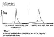
- FIG. 3 shows the IR spectra of PSA-BEA and PtEA-Bea before and after poisoning with 1-adamantanecarbonitrile
- the left spectrum shows the catalyst according to the invention, the right one the catalyst according to Comparative Example 1, prepared with ethanolammonium hexahydroxoplatinate.
- the catalyst according to the invention adsorbs approximately the same amount of carbon monoxide in both the original and the poisoned state. This means that the platinum is not accessible to the nitrile and thus is inside the zeolite (in the pores).
- the adamantane nitrile-poisoned catalyst of Comparative Example 1 adsorbs significantly less CO than the non-poisoned catalyst. This means that the Pt distribution on both zeolites is different and correlates with the activity as well as the stability of the two catalysts. It is thus clearly advantageous to introduce the platinum completely into the interior pore system of the zeolite.
- the different Pt distribution is additionally confirmed by XRD measurements.
- the spectrum of the catalyst according to the invention shows no Pt reflections, whereas the spectrum of the catalyst according to Comparative Example 1 shows clear reflections.
Landscapes
- Chemical & Material Sciences (AREA)
- Engineering & Computer Science (AREA)
- Chemical Kinetics & Catalysis (AREA)
- Materials Engineering (AREA)
- Organic Chemistry (AREA)
- Crystallography & Structural Chemistry (AREA)
- Biomedical Technology (AREA)
- Health & Medical Sciences (AREA)
- Combustion & Propulsion (AREA)
- Environmental & Geological Engineering (AREA)
- Analytical Chemistry (AREA)
- General Chemical & Material Sciences (AREA)
- Oil, Petroleum & Natural Gas (AREA)
- Physics & Mathematics (AREA)
- Thermal Sciences (AREA)
- Catalysts (AREA)
- Exhaust Gas Treatment By Means Of Catalyst (AREA)
Description
- Die vorliegende Erfindung betrifft ein Verfahren zur Herstellung eines erfindungsgemäßen Platin enthaltenden Katalysators, den erfindungsgemäßen Platin enthaltenden Katalysator sowie die Verwendung des Platin enthaltenden Katalysators als Oxidationskatalysator und Kohlenwasserstoffspeicher.
- Zu Beginn der Abgasreinigung von Verbrennungsmotoren wurden nur die Abgase von Benzinmotoren mit Dreiwege-Katalysatoren (TWC) gereinigt. Dabei werden die Stickoxide mit den reduzierenden Kohlenwasserstoffen (HC) und Kohlenmonoxid (CO) reduziert.
- Seit etwa 15 Jahren versucht man auch die Abgase von Dieselmotoren mit Katalysatoren nachzubehandeln. Das Abgas von Dieselmotoren weist Kohlenmonoxid, unverbrannte Kohlenwasserstoffe, Stickoxide und Rußpartikel als Luftschadstoffe auf. Die unverbrannten Kohlenwasserstoffe umfassen Paraffine, Olefine, Aldehyde und Aromaten.
- Ein Abgassystem für Dieselverbrennungsmotoren besteht in der Regel aus den folgenden Komponenten:
- Diesel-Oxidationskatalysator (DOC) zur Oxidation von Kohlenwasserstoffen und als Kohlenwasserstoffspeicher im Kaltstart;
- Dieselpartikelfilter (DPF) zur Verminderung der Partikelemissionen;
- optional ein Hydrolyse-Katalysator zur Harnstoffzersetzung;
- SCR-Katalysator (selective catalytic reduction) zur Reduktion der Stickoxide;
- Sperrkatalysator als Ammoniak-Oxidationskatalysator.
- Unter DOC (Diesel-Oxidationskatalysator) versteht der Fachmann einen Katalysator, welcher vorzugsweise im Kaltstart eine Kohlenwasserstoff-Speicherfunktion erfüllt und im Normalbetrieb unverbrannte Kohlenwasserstoffe oxidiert. Die Behandlung der Abgase von Dieselverbrennungsmotoren mit Katalysatoren erfordert konzeptionelle Änderungen an den Katalysatormaterialien, da ein Dieselmotor im Gegensatz zu einem Benzinmotor immer unter Sauerstoffüberschuss betrieben wird und der Katalysator somit nie reduktiven Bedingungen ausgesetzt ist.
- Seit dem Aufkommen der Diskussion um die Feinstaubproblematik werden den DOC-Katalysatoren noch Partikelfilter nachgeschaltet. Partikelfilter (DPF, Dieselpartikelfilter) werden eingesetzt, um Rußpartikel aus dem Abgas von Verbrennungsmotoren, speziell Dieselmotoren, herauszufiltern und so deren Ausstoß in die Atmosphäre zu vermindern. Dabei kommen verschiedene Filterkonzepte, wie z. B. so genannte "Wall-flow-Filter" oder Filter aus keramischen oder metallischen Schäumen zur Anwendung. Die eigentliche Schwierigkeit besteht aber nicht in der Filtration der Rußpartikel, sondern in der Regeneration der eingesetzten Filter. Kohlenstoffruß verbrennt je nach betriebsbedingter Zusammensetzung der Partikel spontan erst bei Temperaturen zwischen 500°C und 700°C.
- Partikelfilter neuerer Generation müssen aktiv regeneriert werden. Das bedeutet, dass immer wieder eine so hohe Temperatur auf dem DOC erzeugt werden muss, dass der Ruß auf dem nachgeschalteten DPF zündet und abbrennt. Daher spielt die thermische Alterung der DOC-Katalysatoren heute eine wichtige Rolle.
- Dieselfahrzeuge neuerer Generation werden gegenwärtig stromabwärts zum Dieselpartikelfilter mit einer Baueinheit ausgestattet, welche eine selektive katalytische Reduktion von Stickoxiden mithilfe eines sogenannten SCR-Katalysators bewerkstelligen kann. Mit SCR (selective catalytic reduction) wird die selektive katalytische Reduktion von Stickoxiden aus Abgasen von Verbrennungsmotoren und auch Kraftwerken bezeichnet. Mit einem SCR-Katalysator werden nur die Stickoxide NO und NO2 (allgemein als NOx bezeichnet) selektiv reduziert, wobei für die Reaktion gewöhnlich NH3 (Ammoniak) zugemischt wird. Als Reaktionsprodukt entstehen daher nur die unbedenklichen Stoffe Wasser und Stickstoff.
- Von besonderer Wichtigkeit ist daher heute, neben der Oxidation von Kohlenwasserstoffen, die Oxidation von NO zu NO2 in dem Dieseloxidationskatalysator. Das NO2 erleichtert die Regeneration des nachfolgenden Dieselpartikelfilters, d.h. den Rußabbrand (siehe beispielsweise J. Choo et al., Science of the total environment (2008) 396-401; M. Jeguirim et al. Applied Catalysis B: Environmental, 76 (2007), 235-240 oder K. Yamamoto et al., Proceedings of the Combustion institute, 32(1) (2009), 1965-1972). Darüber hinaus kann ein Gemisch aus NO/NO2 schneller durch selektive katalytische Reduktion (SCR) mit Ammoniak zu Stickstoff und Luft zersetzt werden als reines NO (siehe beispielsweise A. Grossale, et al., Journal of Catalysis, 256 (2008), 312 bis 322 oder M. Schwidder, et al., Journal of Catalysis, 259 (2008), 96 bis 103), so dass hier die Aktivität des DOC für die Oxidation von NO zu NO2 auch noch nach Alterung des Katalysators sehr hoch sein muss.
- Somit sind Katalysatoren erforderlich, die unter den Betriebsbedingungen der Dieselabgasnachbehandlung eine geringere Alterungstendenz aufweisen als dies im Stand der Technik bisher möglich ist.
- Im Stand der Technik sind neben Pt-basierten Katalysatoren auch Katalysatoren bekannt, die sowohl Pt als auch Pd enthalten. Ferner enthalten DOC-Katalysatoren häufig Zeolithe, die zur Speicherung der Kohlenwasserstoffe im kalten Zustand dienen (Kaltstartfalle), so dass die Kaltstartemissionen von Kohlenwasserstoffen verringert werden.
- Ein typischer DOC ist beispielsweise in
EP 800 856 A2 - Die Patentanmeldung
US2006/0035780 A1 offenbart einen Dieseloxidationskatalysator, umfassend einen Honigwabenkörper, der mit einer Mischung aus Ton, hitzebeständigem Oxid und einem Zeolith beschichtet wird. Das beschichtete Substrat wird anschließend mit einem Edelmetallkatalysator und einem Schwefeloxidationsunterdrückungsmittel beladen. In einer bevorzugten Ausführungsform ist der Ton ein säureaktivierter Bentonit, das hitzebeständige Oxid ist Zirkondioxid oder Titandioxid, der Zeolith ist Zeolith-Beta, Y-Zeolith, ZSM-5 oder Mordenit, der Edelmetallkatalysator ist vorzugsweise Platin und das Mittel zur Schwefeloxidationsunterdrückung ist Vanadium, Vanadiumoxid oder eine Kombination beider. - Platinhaltige Zeolithe sind im Stand der Technik bekannt. Beispielsweise werden Zeolithe mit sehr geringen Platingehalten (< 1 %) als Katalysatoren im Raffineriebereich eingesetzt, z.B. für Cyclisierungs-, Aromatisierungs-, und Crackreaktionen. Im Gegensatz zu den Bedingungen, die in einem Dieselabgas herrschen, finden die eben genannten Reaktionen unter reduktiven Bedingungen (d.h. Kohlenwasserstoffüberschuss) statt und benötigen deswegen nur sehr geringe Edelmetallgehalte.
- Die Herstellung von Platin enthaltenden Zeolithen, beispielsweise durch Ioneneintausch von Platin in die Poren des Zeolithen, ist im Stand der Technik bekannt. Diese Verfahren führen jedoch nicht zu Platinkonzentrationen im Zeolithen, die für die Verwendung in einem Dieseloxidationskatalysator notwendig wäre (siehe beispielsweise J.M. Garcia-Cortes et al., Journal of Catalysis, 218 (2003), 111 bis 122; C. Jimenez et al., Applied Catalysis A: General 249 (2003), 175 bis 185 und J. Perez-Ramirez et al., Applied Catalysis B: Environmental 29 (2001), 285 bis 298).
- Die Offenlegungsschrift
WO 2009/138204 A2 offenbart ein Verfahren zur Herstellung einer Vorstufe eines geträgerten Platinkatalysators. Um ein Verfahren zur Herstellung einer Platinkatalysator-Vorstufe bereitzustellen, mittels welcher geträgerte Platinkatalysatoren hergestellt werden können, die eine verhältnismäßig hohe Aktivität aufweisen, wird ein Verfahren vorgeschlagen, umfassend die Schritte: a) Imprägnieren eines offenporigen Trägermaterials mit Platinsulfitsäure, b) Kalzinieren des imprägnierten Zeolithmaterials unter einem Schutzgas. - DOC-Katalysatoren mit verbesserter Stabilität werden gewöhnlich auch durch gemischte Pt-/Pd-Katalysatoren bereitgestellt. Insbesondere Pt-/Pd-Katalysatoren mit einem hohen Pt-Anteil (6:1) zeigen eine gute Stabilität gegen thermische Alterung. Nachteilig ist jedoch, dass die NO zu NO2-Oxidation bei steigenden Pd-Gehalten schlechter wird. Außerdem sind die Pt-/Pd-Katalysatoren deutlich weniger resistent gegenüber Schwefel (siehe beispielsweise 5. Internationales Forum Abgas- und Partikelemissionen, 19. und 20. Februar 2008, Ludwigsburg, Seite 126 bis 144). Solche Katalysatoren können gewöhnlich nach einer Schwefelvergiftung nicht thermisch regeneriert werden, sondern verlieren noch weiter an Aktivität, wenn sie nach der Vergiftung thermisch beansprucht, d.h. gealtert werden.
- Aufgabe der vorliegenden Erfindung war somit die Bereitstellung eines Verfahrens zur Herstellung eines Katalysators, insbesondere eines Dieseloxidationskatalysators, der eine geringe Alterungstendenz und eine hohe Aktivität aufweist.
- Die Aufgabe wird gelöst durch ein Verfahren zur Herstellung eines Katalysators, wobei ein Platin enthaltender Zeolith durch folgende Schritte hergestellt wird:
- a) Imprägnieren eines Zeolithen mit einem SiO2/Al2O3-Modul von 5 bis 300 mit einer Platinsulfitlösung,
- b) Kalzinieren des imprägnierten Zeolithen unter einer Schutzgasatmosphäre;
- Das Kalzinieren des imprägnierten Zeolithen soll in einer Schutzgasatmosphäre erfolgen, wobei bevorzugt eine Argonatmosphäre oder eine Stickstoffatmosphäre verwendet wird. Besonders Bevorzugt ist eine Argonatmosphäre.
- Das Kalzinieren des imprägnierten Zeolithen erfolgt vorzugsweise bei einer Temperatur von 600 bis 900 °C, mehr bevorzugt > 750 bis 850 °C, besonders bevorzugt > 750 bis 830°C, insbesondere bei etwa 800°C.
- Durch das Kalzinieren entsteht eine PlatinVorläuferverbindung, welche, falls erforderlich, bevorzugt im Anschluss an das Kalzinieren reduziert wird. Prinzipiell kann eine Reduktion jedoch auch schon während des Kalzinierens erfolgen, wobei dann jedoch eine reduzierende Atmosphäre anstelle der Schutzgasatmosphäre eingesetzt werden müsste.
- Eine Reduktion, welche im Anschluss an das Kalzinieren erfolgen kann, wird vorzugsweise aus einem Gemisch aus einem Reduktionsgas (Wasserstoff, Kohlenmonoxid, Ethen, einem Methanol, Ethanol etc.) und einem Inertgas durchgeführt. Bevorzugte Inertgase sind beispielsweise Argon, Helium, Neon und dergleichen. Das Inertgas in dem Reduktionsschritt ist als Trägergas zu verstehen, wobei Wasserstoff oder ein anderes reduktives Gas bevorzugt in einer Konzentration von 1 bis 10 Vol.-%, mehr bevorzugt 3 bis 7 Vol.-%, besonders bevorzugt etwa 5 Vol.-%, bezogen auf das Gesamtvolumen aus Reduktionsgas und Inertgas, beträgt.
- Die Reduktion wird gewöhnlich solange durchgeführt, bis eine vollständige bzw. nahezu vollständige Umsetzung der Platinvorläuferverbindung erfolgt ist. Bevorzugt wird die Reduktion über einen Zeitraum von 3 bis 7 Stunden, mehr bevorzugt 4 bis 6 Stunden, besonders bevorzugt etwa 5 Stunden durchgeführt.
- Die Reduktion wird bevorzugt bei erhöhten Temperaturen durchgeführt. Bevorzugt wird die Reduktion bei einer Temperatur von 200 bis 500 °C, mehr bevorzugt 250 bis 350 °C, am meisten bevorzugt etwa 300 °C durchgeführt. Für die Reduktion wird der Katalysator gewöhnlich in ein Katalysatorbett gegeben und dabei von dem Reduktionsmittel durchströmt. Ebenso kann der Katalysator mit dem Reduktionsgas überschichtet und vorteilhafterweise auf eine erhöhte Temperatur gebracht werden. Die Erhöhung der Temperatur kann beispielsweise dadurch erfolgen, dass das Katalysatorbett erwärmt wird. Ebenso ist es möglich, dass das Reduktionsgas bereits im Vorfeld erwärmt wird, beispielsweise indem die Gaszuleitung erwärmt wird, wobei dann das erwärmte Reduktionsgas über den zu reduzierenden Katalysator geleitet wird.
- Das Imprägnieren des Zeolithen mit der Platinsulfitlösung kann über eine Tauchimprägnierung, Sprühimprägnierung oder Incipient-Wetness-Methode erfolgen. Bevorzugt erfolgt die Imprägnierung über eine Incipient-Wetness-Methode, obwohl gemäß Stand der Technik normalerweise bei dieser Imprägniermethode nur ein geringer Teil der Metallcluster in die Poren wandert und ein erheblicher Teil auf der äußeren Zeolithoberfläche verbleibt.
- Überraschend wurde jedoch gefunden, dass sich durch Imprägnierung, z.B. Incipient-Wetness-Imprägnierung, des Zeolithen mit einem SiO2/Al2O3-Modul von 5 bis 300 mit Platinsulfitsäure (PSA) und anschließender Kalzinierung unter Schutzgas bei hohen Temperaturen, wobei der Platin enthaltende Zeolith als Washcoat verarbeitet und auf einen Katalysatorträgerkörper aufgebracht wird und dass Platin nur auf eine Komponente, nämlich den Zeolithen, aufgebracht ist, ein Katalysator herstellen lässt, der auch noch nach dieser hohen Temperaturbelastung den größten Teil des Platins in den Zeolithporen aufweist. Dies kann über ein Röntgendiffraktogramm (XRD) und über CO-Adsorption (nach selektiver Vergiftung der Pt-Cluster auf der Oberfläche) im FTIR nachgewiesen werden. XRD und FTIR sind Standard-Analytikmethoden in der Chemie.
- Überraschenderweise wurde auch gefunden, dass der so hergestellte Katalysator eine erhöhte Schwefelresistenz aufweist als bereits bekannte Systeme. Die katalytische Aktivität des thermisch gealterten erfindungsgemäßen Katalysators wird durch eine Schwefelvergiftung und anschließende Hochtemperaturentschwefelung nicht verändert.
- Der entwickelte Katalysator zeigt zwar ein vergleichbares Alterungsverhalten bezüglich der Oxidation von Kohlenstoffmonoxid wie bestehende Pt-basierte Katalysatoren, überraschenderweise wurde aber gefunden, dass er in Bezug auf die Oxidation von NO eine deutlich bessere Stabilität aufweist.
- Ein weiterer Vorteil des erfindungsgemäß hergestellten Katalysators gegenüber dem Stand der Technik ist ferner, dass das Edelmetall nur auf eine Komponente, den Zeolith, aufgebracht ist, und nicht wie bei anderen Katalysatoren auf einem Gemisch von Zeolith und zusätzlichen oxidischen Trägern.
- Dadurch können Herstellungsschritte und somit auch Kosten eingespart werden.
- Durch den erhöhten Zeolithanteil wird zudem die Speicherkapazität für Kohlenwasserstoffe deutlich erhöht (siehe beispielsweise
EP 691 883 B1 US 5,804,155 undEP 830 301 - Unter dem Begriff "Zeolith" wird im Rahmen der vorliegenden Erfindung gemäß der Definition der International Mineralical Association (D.S. Coombs et al., Canadian Mineralogist, 35, 1979, 1571) eine kristalline Substanz aus der Gruppe der Aluminiumsilikate mit einer Raumnetzstruktur der allgemeinen Formel
Mx/n[(AlO2)x (SiO2)y]x(H2O)z
verstanden, die aus SiO4/AlO4-Tetraeder bestehen, die durch gemeinsame Sauerstoffatome zu einem regelmäßigen dreidimensionalen Netzwerk verknüpft sind. - Das Verhältnis von Si/Al=y/x beträgt immer > 1 gemäß der sog. "Löwenstein-Regel", die das benachbarte Auftreten zweier benachbarter negativ geladener AlO4-Tetraeder verbietet. Dabei stehen bei einem geringen Si/Al-Verhältnis zwar mehr Austauschplätze für Metall zur Verfügung, der Zeolith wird jedoch zunehmend thermisch instabiler.
- Die Zeolithstruktur enthält Hohlräume, Kanäle, die für jeden Zeolithen charakteristisch sind. Die Zeolithe werden gemäß ihrer Topologie in verschiedene Strukturen eingeteilt. Das Zeolithgerüst enthält offene Hohlräume in Form von Kanälen und Käfigen, die normalerweise mit Wassermolekülen und zusätzlichen Gerüstkationen besetzt sind, die ausgetauscht werden können. Auf ein Aluminiumatom kommt eine überschüssige negative Ladung, die durch diese Kationen kompensiert wird. Das Innere des Porensystems stellt die katalytisch aktive Oberfläche dar. Je mehr Aluminium und je weniger Silizium ein Zeolith enthält, desto dichter ist die negative Ladung in seinem Gitter und desto polarer seine innere Oberfläche. Die Porengröße und Struktur wird neben den Parametern bei der Herstellung, d.h. Verwendung bzw. Art von Templaten, pH, Druck, Temperatur, Anwesenheit von Impfkristallen, durch das Si/Al-Verhältnis (Modul) bestimmt, das den größten Teil des katalytischen Charakters eines Zeolithen ausmacht.
- Vorzugsweise enthält der erfindungsgemäße Zeolith mindestens 2 Gew.-% Platin, vorzugsweise mindestens 3 Gew.-%, am meisten bevorzugt 3,5 oder mehr Gew.- % Platin, wobei sich mindestens 90 % des Platins in den Poren des Zeolithen befinden, mehr bevorzugt mindestens 95 %, insbesondere bevorzugt mindestens 99 %.
- Bevorzugt ist der Zeolith ausgewählt aus den Gruppen bestehend aus den Typen AEL, BEA, CHA, EUO, FAU, FER, KFI, LTA, LTL, MAZ, MOR, MEL, MTW, LEV, OFF, TON, und MFI. Besonders bevorzugt ist die BEA-Struktur.
- Der Zeolith weist ein SiO2 /Al2O3 Modul von 5 bis 300, bevorzugt von 10 bis 200, mehr bevorzugt von 15 bis 100, auf.
- Der Zeolith in dem erfindungsgemäßen Katalysator zeichnet sich durch eine Pt-C=O Streckschwingung zwischen 2070 und 2110 cm-1, vorzugsweise bei etwa 2080 bis 2095 cm-1 aus. Die Streckschwingung ist selbst nach einer Vergiftung mit Adamantancarbonitril vorhanden. Adamantancarbonitril ist ein sterisch anspruchsvolles Molekül, das auf Grund seiner Größe nicht in das Porensystem des Zeolithen eindringen kann. Durch die Adsorption von Adamantancarbonitril werden daher nur Pt-Cluster auf der äußeren Oberfläche des vergiftet. Wird im Anschluss an diese Vergiftung CO adsorbiert, kann dieses nur noch an die nicht vergifteten Pt-Cluster im inneren des Zeolithen binden. Das Vorhanden sein der Pt-C=O Streckschwingung nach der Vergiftung mit Adamantancarbonitril beweist, dass das Pt in den Poren des Zeolithen sitzt. Die verbleibende Intensität nach einer Vergiftung ist etwa 2- bis 4-fach höher als bei einem Vergleichskatalysator.
- Der Zeolith in dem erfindungsgemäßen Katalysator ist ferner im Röntgendiffraktogramm (XRD) frei von Pt-Reflexen. Dies zeigt ebenfalls, dass das Platin in den Poren des Zeolithen sitzt.
- Ein weiterer Gegenstand der Erfindung ist die Verwendung des erfindungsgemäßen Katalysators als Oxidationskatalysator und Kohlenwasserstoffspeicher. Zeolithe sind als Kohlenwasserstoffspeicher bekannt. In Verbindung mit der hohen Platindispersion in den Poren des Zeolithen eignet er sich jedoch auch hervorragend als Oxidationskatalysator mit entsprechender kumulierter Kohlenwasserstoffspeicherfunktion. Dadurch, dass Platin lediglich auf einen Zeolithen aufgebracht wird und nicht, wie im Stand der Technik bekannt, auf andere Metalloxide, ergibt sich ein einfaches Katalysatorsystem, das kostengünstig hergestellt werden kann.
- Der Zeolith kann vorteilhaft zu einem Washcoat verarbeitet werden und entsprechend auf einen Katalysatorträgerkörper aufgebracht werden. Wie ein solcher Washcoat hergestellt werden kann, ist dem Fachmann bekannt. Die notwendigen Beschichtungstechniken zur Beschichtung eines Katalysatorträgerkörpers sind dem Fachmann ebenfalls bekannt.
- So wird z.B. der imprägnierte und getrocknete Zeolith zu einer wässrigen Beschichtungsdispersion verarbeitet. Dieser Dispersion kann ein Binder, z.B. Silikasol, zugegeben werden. Die Viskosität der Dispersion kann durch die eigenen Zusatzstoffe eingestellt werden, so dass es möglich wird, die benötigte Beschichtungsmenge in einem einzigen Arbeitsgang auf die Wandungen der Strömungskanäle aufzubringen. Ist dies nicht möglich, so kann die Beschichtung mehrfach wiederholt werden, wobei die frisch aufgebrachte Beschichtung jeweils durch eine Zwischentrocknung fixiert und bei Bedarf kalziniert wird.
- Für die Abgasreinigung von Dieselmotoren sind Beschichtungsmengen von 50 bis 500 g/l, bevorzugt 250 bis 350 g/l Volumen des Katalysatorträgerkörpers vorteilhaft.
Als Katalysatorträger kann ein metallischer oder keramischer Monolith, ein Vlies- oder ein Metallschaum verwendet werden. Auch andere im Stand der Technik bekannte Katalysatorformkörper bzw. Katalysatorträgerkörper sind erfindungsgemäß geeignet. Besonders bevorzugt ist ein metallischer oder keramischer Monolith, der eine Vielzahl von parallelen Durchtrittsöffnungen aufweist, welche mit der Washcoatbeschichtung versehen werden. Vorzugsweise weist der Trägerkörper Durchtrittsöffnungen mit rundem, dreieckigem, viereckigem oder polygonalem Querschnitt auf. Besonders bevorzugt ist der Träger als monolithischer Honigwabenkörper ausgebildet. - Metallische Wabenkörper sind häufig aus Metallblechen oder Metallfolien gebildet. Dabei werden die Wabenkörper beispielsweise durch abwechselnde Anordnung von Lagen strukturierter Bleche bzw. Folien hergestellt. Vorzugsweise bestehen diese Anordnungen aus einer Lage eines glatten Blechs im Wechsel mit einem gewellten Blech, wobei die Wellung beispielsweise sinusförmig, trapezförmig, omegaförmig oder zickzackförmig ausgebildet sein kann. Entsprechende metallische Wabenkörper und Verfahren zu ihrer Herstellung werden beispielsweise in der
EP 0 049 489 A1 oder derDE 28 56 030 A1 beschrieben. - Im Bereich der Katalysatorträgerkörper haben metallische Wabenkörper den Vorteil, dass sie sich schneller erwärmen und damit in der Regel Katalysatorträgerkörper auf der Basis von metallischen Substraten ein besseres Ansprechverhalten bei Kaltstartbedingungen zeigen.
- Vorzugsweise weist der Wabenkörper eine Zelldichte von 30 bis 1500 cpsi, besonders bevorzugt von 200 bis 600 cpsi, insbesondere etwa 400 cpsi, auf.
- Der Katalysatorträgerkörper, auf den der Zeolith aufgebracht sein kann, kann aus einem beliebigen Metall oder einer Metalllegierung gebildet und z. B. durch Extrusion oder durch Aufwickeln oder Stapeln oder Falten von Metallfolien hergestellt sein. Bekannt im Bereich der Abgasreinigung sind temperaturbeständige Legierungen mit den Hauptbestandteilen Eisen, Chrom und Aluminium. Bevorzugt für den erfindungsgemäßen Katalysator sind frei durchströmbare monolithische Katalysatorträgerkörper mit oder ohne innere Anströmkanten zur Abgasverwirbelung oder Metallschäume, die eine große innere Oberfläche aufweisen und an denen der erfindungsgemäße Katalysator sehr gut haftet. Jedoch lassen sich auch Katalysatorträgerkörper mit Schlitzen, Lochungen, Perforationen und Prägungen in der Metallfolie einsetzen.
- In gleicher Weise können Katalysatorträgerkörper aus keramischem Material eingesetzt werden. Bevorzugt handelt es sich bei dem keramischen Material um ein inertes, niedrig oberflächiges Material wie Cordierit, Mullit, AluminiumTitanat oder α-Aluminiumoxid. Jedoch kann der verwendete Katalysatorträger auch aus hochoberflächigem Trägermaterial wie γ-Aluminiumoxid bestehen.
- Ebenso kann ein Metallschaum, beispielsweise ein metallisches offenporiges Schaummaterial, als Katalysatorträgerkörper eingesetzt werden. Im Rahmen der vorliegenden Erfindung soll unter dem Begriff "metallisches offenporiges Schaummaterial" ein Schaummaterial aus einem beliebigen Metall oder aus einer beliebigen Legierung verstanden werden, das gegebenenfalls auch noch Zuschlagsstoffe enthalten kann und das eine Vielzahl von Poren aufweist, die miteinander leitungsverbunden sind, so dass beispielsweise durch das Schaummaterial ein Gas hindurch geleitet werden kann.
- Metallische offenporige Schaummaterialien haben durch die Poren und Hohlräume bedingt eine sehr geringe Dichte, weisen jedoch eine beträchtliche Steifigkeit und Festigkeit auf. Die Herstellung von Metallschäumen erfolgt beispielsweise mittels eines Metallpulvers und eines Metallhydrids. Beide Pulver werden in der Regel miteinander vermischt und dann durch Heißpressen oder Strangpressen zu einem Formmaterial verdichtet. Das Formmaterial wird dann auf eine Temperatur oberhalb des Schmelzpunktes der Metalle erhitzt. Dabei setzt das Metallhydrid Wasserstoffgas frei und schäumt das Gemenge auf.
- Es gibt jedoch auch noch andere Möglichkeiten, Metallschäume herzustellen, beispielsweise durch Einblasen von Gas in eine Metallschmelze, die zuvor durch Zugabe fester Bestandteile schäumbar gemacht wurde. Für Aluminiumlegierungen beispielsweise werden zur Stabilisierung 10 bis 20 Vol.-% Siliziumcarbid oder Aluminiumoxid zugegeben. Darüber hinaus lassen sich offenporige metallische Schaumstrukturen mit einem Porendurchmesser von 10 ppi bis circa 50 ppi durch spezielle Feingusstechniken herstellen.
- Der Träger kann prinzipiell auch extrudiert und spritzgegossen werden. Auch hier sind metallische und keramische Materialien möglich, wobei im Falle der keramischen Materialien beispielsweise Formhilfsmittel zugegeben werden und beispielsweise auch Bindemittel und sonstige Zusatzstoffe. Extrudierte Träger können beliebige Geometrien einnehmen, vorzugsweise die oben genannten.
- Die Erfindung soll nun anhand einiger nicht als beschränkend auf den Umfang der Erfindung zu verstehenden Ausführungsbeispiele näher erläutert werden.
- Der erfindungsgemäße Katalysator wird nach folgender Vorschrift hergestellt:
- Zuerst wurde die Wasseraufnahme eines getrockneten Zeolithen bestimmt (H-BEA-35:kommerzielles Produkt der Süd-Chemie AG). Sie betrug 92,3 %.
- 24,1 g einer Platinsulfitlösung (10,17 Gew.-% Pt-Gehalt) wurden mit destilliertem Wasser auf 62,3 g aufgefüllt. Mit dieser Lösung wurden in einem Mörser 67,55 g des getrockneten Zeolithen imprägniert. Die Platinkonzentration betrug 3,5 Gew.-%. Das feuchte Pulver wurde bei 120 °C getrocknet und anschließend 5 Stunden bei 800 °C unter Schutzgas (V = 2 l/min) kalziniert und mit 5 % H2 in N2 für 5 h bei 300 °C reduziert.
- 70 g des Pulvers wurde mit Hilfe eines Ultra-Turrax-Rührers in 230 ml Wasser suspendiert. Die Suspension wurde mit einer Planetenkugelmühle (Retsch PM 100) mit 10 mm Kugeln aus Yttrium-stabilisierten Zr-Oxid auf eine Partikelgröße von d50 ∼ 2 µm gemahlen. Mit diesem Washcoat wurde eine Coderieritwabe (400 cpsi) beschichtet und kalziniert, so dass am Ende 3,5 g Pt/L-Wabenvolumen auf der Wabe enthalten waren.
- Um den Einfluss der Reduktion zu untersuchen, wurde eine zweite Wabe mit einem nicht reduzierten Katalysator (sonst analog zu Bsp. 1) beschichtet.
- Als Vergleich wurde die gleiche Synthese mit Ethanolammoniumhexahydroxoplatinat-Lösung (13,59 Gew.-% Pt-Gehalt) als Pt-Quelle durchgeführt. Die Pt-Konzentration betrug ebenfalls 3,5 Gew.-%.
- In Anlehnung an
DE 10 2007 057 305 undEP 800 856 B1 - Es wurde zuerst die Wasseraufnahme eines Mischoxides aus Aluminiumoxid und Siliziumoxid (Siralox 5/140, 5 % Si, von Condea) bestimmt. Sie betrug 53,86 %. 110,4 g einer Lösung von Ethanolammoniumhexahydroxoplatinat (13,59 % Pt-Gehalt) wurde (mit H2O dest.) auf 161,6 ml aufgefüllt. Mit dieser Lösung wurden in einem Planetenmischer 300 g des Siraloxpulvers imprägniert. Das feuchte Pulver wurde im Ofen 3 h bei 80 °C getrocknet und dann 3 h bei 550 °C kalziniert.
- 140 g des Pulvers wurde mit Hilfe eines Ultra-Turrax-Rührers in 700 ml Wasser suspendiert. Die Suspension wird mit einer Perlenmühle (Dynomil Fa. WAB) mit 1 - 1,2 mm Perlen aus Zr/Ce-Oxid auf eine Partikelgröße d50 ∼ 3 µm gemahlen. Zu dieser fein gemahlenen Dispersion von Pt/Siralox wurde 140 g eines mit Eisen ausgetauschten β-Zeolithen (3 % Fe2O3, β-35-Zeolith) gegeben und die Suspension auf 1400 ml aufgefüllt, so dass ein Beschichtungswashcoat von 20 % Feststoffgehalt entstand. Mit diesem Washcoat wurde eine Cordieritwabe (400 cpsi) beschichtet und kalziniert, so dass am Ende 3,5 g Pt/l-Wabenvolumen auf der Wabe enthalten waren.
- Als Vergleich der katalytischen Aktivität und der Alterung wurde zusätzlich ein handelsüblicher DOC-Katalysator eines Daimler OM646-Motors eingesetzt.
- Es wurde zuerst die Wasseraufnahme eines Mischoxides aus Aluminiumoxid und Siliziumoxid (Siralox 5/140 Typ C mit sehr großen Poren und 5 % Si von Condea) bestimmt. Sie betrug 151 %. 67,39 g einer Lösung von Ethanolammoniumhexahydroxoplatinat (13,85 % Pt-Gehalt) wurde mit 58 ml destilliertem Wasser aufgefüllt. Mit dieser Lösung wurde in einem Planetenmischer 186 g des Siraloxpulvers in einem ersten Schritt imprägniert. Dann wurde 17,34 g einer Palladiumnitratlösung mit 58 ml Wasser verdünnt und im nächsten Schritt weiter als Imprägnierlösung zu dem feuchten Pulver im Planetenmischer zugetropft. Das feuchte Pulver wurde im Ofen 3 h bei 80 °C getrocknet und dann 3 h bei 550 °C kalziniert. Das Pulver enthielt 7 % Gesamtedelmetallgehalt.
- 140 g des Pulvers wurde mit Hilfe eines Ultra-Turrax-Rührers in 700 ml Wasser suspendiert. Die Suspension wurde mit einer Perlenmühle (Dynomill Fa. WAB) mit 1 - 1,2 mm Perlen aus Zr/Ce-Oxid auf eine Partikelgröße d50 ∼ 3 µm gemahlen. Mit diesem Washcoat wurde eine Cordieritwabe (400 cpsi) beschichtet und kalziniert, so dass am Ende 3,5 g Edelmetall/L-Wabenvolumen auf der Wabe enthalten waren.
- Es wurde zuerst die Wasseraufnahme eines Mischoxids aus Aluminiumoxid und Siliziumoxid (Siralox 5/140 Typ C mit sehr großen Poren und 5 % Si von Condea) bestimmt. Sie betrug 151 %. 73,6 einer Lösung von Ethanolammoniumhexahydroxoplatinat (13,59 % Pt-Gehalt) wurde mit destilliertem Wasser auf 181 ml aufgefüllt. Mit dieser Lösung wurde in einem Planetenmischer 200 g des Siraloxpulvers imprägniert. Das feuchte Pulver wurde im Ofen 3 h bei 80 °C getrocknet und dann 3 h bei 550 °C kalziniert.
- 100 g des Pulvers wurde mit Hilfe eines Ultra-Utrax-Rührers in 200 ml Wasser suspendiert. Die Suspension wurde mit einer Planetenkugelmühle (Ra. Retsch) mit 10 mm Perlen aus Zr-Oxid auf eine Partikelgröße von d50 ∼ 3 µm gemahlen. Zum Entleeren des Mahlbehälters wurden noch 200 g Wasser zugegeben. Mit diesem Washcoat wurde eine Cordieritwabe (400 cpsi) beschichtet und kalziniert, so dass am Ende 3,5 g Pt/l-Wabenvolumen auf der Wabe enthalten waren.
- Die in den Beispielen 1 und 2 und den Vergleichsbeispielen hegestellten Katalysatorwaben wurden in einem Reaktor unter folgenden Bedingungen auf die Oxidation von CO, Propen und NO getestet:
-
CO: 500 ppm NO: 500 ppm Propen: 500 ppm Sauerstoff: 5 % Wasserdampf: 10 % CO2: 70 -90 ppm Stickstoff: Rest - Die Katalysatorwabe wurde mit einer Keramikfasermatte in ein Quarzglasrohr eingebaut. Der Gasstrom wurde vor dem Katalysator elektrisch aufgeheizt. Für den Test wurde der Katalysator erst 30 min unter diesen Gasbedingungen bei 390 °C betrieben und dann in Schritten von 20 °C abgekühlt. Dabei wurde jede Temperatur 8 min gehalten und die Produktzusammensetzung zwischen 7 und 8 min bestimmt. Unterhalb von 250 °C erfolgte die Abkühlung in 5 °C-Schritten um speziell die CO-Light-Off-Temperatur (50 % CO-Umsatz) genauer bestimmen zu können.
- Nach diesem Test wurde der Katalysator mit Luft mit 10 % Wasserdampf mit einer Raumgeschwindigkeit von 5000 h-1 durchströmt und unter diesen Gasbedingungen auf 750 °C (gemessen im Monolith) innerhalb von 2 h aufgeheizt. Unter diesen Bedingungen wurde der Katalysator 10 h gealtert. Dann wurde die oben beschriebene Messung wiederholt.
-
Figur 1 zeigt die den CO-Umsatz der erfindungsgemäßen und der Vergleichskatalysatoren. Tab. 1 zeigt die ausFigur 1 entnommenen Light-Off-Temperaturen (50 % Umsatz an CO).Tabelle 1: CO-Light-Off-Temperaturen (50 % Umsatz) Beispiel CO-LOT frisch [°C] CO-LOT gealtert [°C] Bsp. 1 196 225 Bsp. 2 189 224 Vgl. Bsp. 1 245 278 Vgl. Bsp. 2 191 233 Vgl. Bsp. 3 200 220 - Es ist klar zu erkennen, dass der reine Zeolith-Katalysator, der Pt auch an der Oberfläche in größeren Clustern aufweist, was durch die Herstellung mit PtEA-Imprägnierung unvermeidlich war (Vergleichsbeispiel 1), deutlich schlechter ist, als der erfindungsgemäße Katalysator.
- Es ist auch zu erkennen, dass der erfindungsgemäße Katalysator hinsichtlich der CO-Light-Off-Temperaturen mit handelsüblichen (Vgl. Bsp. 3) und reproduzierten State-of the Art DOC-Katalysatoren (Vgl. Bsp. 2), die auf amorphen Al/Si-Mischoxiden als Platinträger beruhen, sowohl im frischen Zustand, als auch nach Alterung vergleichbar ist. Außerdem ist aus dem Vergleich aus Beispiel 1 und 2 zu erkennen, dass eine Reduktion des Katalysators vor der Reaktion hier keine Rolle spielt. Durch die Testbedingungen von 30 min unter einer oxidierenden Gasmischung bei 390 °C werden derartige Effekte für die erfindungsgemäßen Katalysatoren aufgehoben. Es können also Katalysatoren mit Pt(0) oder oxidischer Vorstufe eingesetzt werden.
-
Figur 2 und Tab. 2 zeigen die NO2-Ausbeute dieser Katalysatoren. Eine hohe NO2-Ausbeute ist erwünscht für die passive Regeneration eines DPF, welcher einem DOC nachgeschaltet ist und im Falle einer SCR-Stufe zur Stickoxidreduktion nach diesem DOC.Tabelle 2: Maximale NOa-Ausbeute Beispiel Max. NO2-Ausbeute [%] frisch Max. NO2-Ausbeute [%] gealtert Bsp. 1 50 37 Bsp. 2 52 33 Vgl. Bsp. 1 32 15 Vgl. Bsp. 2 60 21 Vgl. Bsp. 3 59 16 - Es ist klar zu erkennen, dass nur der erfindungsgemäße Katalysator nach Alterung mit 37 und 33 % NO2-Ausbeute noch eine relativ hohe Aktivität für die Oxidation von NO zu NO2 aufweist.
- Da bekannt ist, dass Pt/Pd-Katalysatoren alterungsstabiler, aber dafür schwefelempfindlicher sind als reine Platinkatalysatoren, wurde nach der Alterung noch ein Test mit Schwefelvergiftung nach Alterung durchgeführt.
- Zu diesem Zweck wurde erst, wie in Beispiel 6 beschrieben, ein Aktivitätstest von 390 °C abwärts durchgeführt, dann die Alterung, wie in Beispiel 6 beschrieben und dann wieder ein Test nach der thermischen Alterung. Danach wurde mit einer Raumgeschwindigkeit von 5000 h-1 ein Gasgemisch aus 20 ppm SO2 in Luft bei 250 °C für 2 h über den Katalysator geleitet. Anschließend wurde wieder eine Aktivitätsmessung, ausgehend von 390 °C abkühlend, durchgeführt. Dann wurde der Katalysator unter Luft mit 10 % Wasserdampf bei einer Raumgeschwindigkeit von 5000 h-1 wieder entschwefelt, indem über einen Zeitraum von 1 h von 150 °C auf 750 °C aufgeheizt und dann 15 min bei 750 °C gehalten wurde. Nach dieser Hochtemperaturentschwefelung wurde erneut ein Aktivitätstest ausgehend von 390 °C abkühlend durchgeführt, wie in Beispiel 6 beschrieben.
- Tab. 3 zeigt die CO-Light-Off-Temperaturen für die verschiedenen Katalysatoren:
Tabelle 3: CO-Light-Off-Temperaturen nach SO2-Alterung Beispiel Zusammensetzung CO-Light-Off-Temperatur [°C] frisch 750 °C gealtert 250 °C 2h +SO2 750 °C 15 min entschwefelt Bsp. 1 Pt/β-Zeolith gemäß Erfindung 196 225 237 218 Vgl. Bsp. 4 Pt/Pd (Siralox) 180 165 178 166 Vgl. Bsp. 5 Pt/Siralox 198 225 230 236 - Es ist klar zu erkennen, dass der erfindungsgemäße Katalysator sich hier sehr ähnlich dem reinen Platinkatalysator gemäß Stand der Technik auf amorphem Al/Si-Oxid verhält (Vgl. Bsp. 5). Der Pt/Pd-Katalysator (Vgl. Bsp. 4) ist wesentlich thermostabiler. Die optimale Pt/Pd-Legierung war durch Kalzinieren bei 550 °C bei der Herstellung noch nicht ausgebildet, so dass der Katalysator bei der 750 °C-Alterung sogar noch besser wurde. Es ist auch zu sehen, dass die Schwefelvergiftung sowohl für den Pt/Pd-Katalysator, als auch für den erfindungsgemäßen Katalysator für die CO-Oxidation annähernd reversibel ist. Der große Vorteil des erfindungsgemäßen Pt-Katalysators zeigt sich aber, wenn man die NO-Oxidation betrachtet Die maximalen Ausbeuten an NO2 sind in Tabelle 4 dargestellt.
Tabelle 4: NO-Oxidation nach Schwefelalterung Beispiel Zusammensetzung Maximale NO2-Ausbeute in [%] frisch 750 °C gealtert 250 °C 2 h +SO2 750 °C 15 min entschwefelt Bsp. 1 Pt/β-Zeolith nach Erfindung 50 37 39 37 Vgl. Bsp. 4 Pt/Pd (4:1) 51 43 38 28 Vgl. Bsp. 4 Pt/Siralox 56 21 22 22 - Es ist klar zu erkennen, dass der erfindungsgemäße Katalysator eine geringere thermische Alterung zeigt als der reine Platinkatalysator (Vgl. Bsp. 5), aber nach dieser thermischen Alterung unabhängig vom Schwefel unverändert bleibt. der Pt/Pd-Katalysator (Vgl. Bsp. 4) ist zwar auch thermisch stabiler, aber auch nach der drastischen thermischen Alterung wird er noch durch Schwefel deaktiviert. Gerade wenn der Katalysator nach einer Beladung mit Schwefel hoch erhitzt wird, wird er bei dem Desulfatisierungsvorgang für die NO-Oxidation stark deaktiviert. Dass in der Tat eine Desulfatisierungsreaktion stattgefunden hat, ist daran zu sehen, dass die CO-Oxidation wieder besser wurde (Tab. 3, Vgl. Bsp. 4). Bei diesem Desulfatisierungsprozess wurde aber der Pt/Pd-Katalysator nochmals erheblich für die NO-Oxidation deaktiviert (max. NO2-Ausbeute 28 %). Diese Deaktivierung ist bei dem erfindungsgemäßen Katalysator nicht zu beobachten dieser Prozess ist aber in der Praxis sehr relevant. Wenn ein DOC-Katalysator in einem System mit aktiv regenerierten DPF häufig durch Kohlenwasserstoffverbrennung hohe Temperaturen zur DPF-Regeneration erzeugen muss, ist diese Deaktivierung sehr entscheidend. In den Normalbetriebsphasen des Katalysators zwischen den Regenerationen arbeitet der Katalysator immer in SO2-haltigem Abgas bei tieferer Temperatur (0 - 500 °C). Er wird hier mit SO2 beladen. Jede aktive Regenerierung bedeutet ein Temperaturplus mit sehr hoher Temperatur und führt zu der hier beschriebenen Deaktivierung der Pt/Pd-Katalysatoren nach dem Stand der Technik, aber nicht zu einer Deaktivierung des erfindungsgemäßen Katalysators.
- Um die Pt-Verteilung auf dem Zeolithen zu bestimmen, wurde eine IR-Spektroskopische Methode entwickelt. Die Methode beruht auf dem Vergleich der Pt-C=O Streckschwingung vor und nach der Adsorption von 1-Adamantancarbonitril. bei 1-Adamantancarbonitril handelt es sich um ein sterisch anspruchsvolles Molekül, das auf Grund seiner Größe nicht in das Porensystem des Zeolithen eindringen kann und deshalb selektiv an die Pt-Cluster auf der äußeren Oberfläche bindet. Vergleicht man die Menge an Kohlenstoffmonoxid, die vor und nach der Vergiftung an die Pt-Cluster bindet, kann die Verteilung des Pt bestimmt werden.
- Aus dem Pt-Zeolith Pulver wurde ein Pressling mit ca. 20 mg hergestellt. Dieser Pressling wurde vor der Messung bei 400 °C im Hochvakuum (~10-7 mbar) über Nacht getrocknet.
- Vor der Messung des Referenzspektrums wurden 20 mbar Kohlenstoffmonoxid auf der Probe adsorbiert. Dann wurde die erste Messung der gesamten adsorbierten CO-Menge durchgeführt. (Integral des CO-Peaks). Vor der Vergiftung wurde die Probe erneut bei 400 °C thermisch behandelt um das Kohlenstoffmonoxid zu desorbieren und somit die Vergiftung mit 1-Adamantancarbonitril zu ermöglichen. Für die Vergiftung wurden 2,5 mbar des Nitrils absorbiert und danach erneut 20 mbar CO zudosiert. Nach ca. 10 min wurde das Vergleichsspektrum gemessen.
-
Figur 3 zeigt die IR-Spektren von PSA-BEA und PtEA-Bea vor und nach der Vergiftung mit 1-Adamantancarbonitril - Das linke Spektrum zeigt den erfindungsgemäßen Katalysator, das rechte den Katalysator gemäß Vergleichsbeispiel 1, hergestellt mit Ethanolammonium-hexahydroxoplatinat. Der erfindungsgemäße Katalysator adsorbiert sowohl im ursprünglichen als auch im vergifteten Zustand annähernd die gleiche Menge Kohlenstoffmonoxid. Das bedeutet, dass das Platin für das Nitril nicht zugänglich ist und sich folglich im Inneren des Zeolithen (in den Poren) befindet. Im Gegensatz dazu, adsorbiert der mit Adamantannitril vergiftete Katalysator gemäß Vergleichsbeispiel 1 deutlich weniger CO als der unvergiftete Katalysator. Das bedeutet, dass die Pt-Verteilung auf beiden Zeolithen unterschiedlich ist und mit der Aktivität als auch der Stabilität der beiden Katalysatoren korreliert. Es ist also eindeutig von Vorteil, das Platin vollständig in das Innere Porensystem des Zeolithen einzubringen.
- Die unterschiedliche Pt-Verteilung wird zusätzlich durch XRD-Messungen bestätigt. Das Spektrum des erfindungsgemäßen Katalysators zeigt keine Pt-Reflexe, wohingegen das Spektrum des Katalysators gemäß Vergleichsbeispiel 1 deutliche Reflexe zeigt.
Claims (18)
- Verfahren zur Herstellung eines Katalysators, wobei ein Platin enthaltender Zeolith durch folgende Schritte hergestellt wird:a) Imprägnieren eines Zeolithen mit einem SiO2/Al2O3-Modul von 5 bis 300 mit einer Platinsulfitlösung,b) Kalzinieren des imprägnierten Zeolithen unter einer Schutzgasatmosphäre;wobei der Platin enthaltende Zeolith als Washcoat verarbeitet und auf einen Katalysatorträgerkörper aufgebracht wird, dadurch gekennzeichnet, dass Platin, nur auf eine Komponente, nämlich den Zeolithen, aufgebracht ist.
- Verfahren zur Herstellung eines Katalysators gemäß Anspruch 1, wobei das Kalzinieren in einer Argon-, Helium-, Neon- oder Stickstoffatmosphäre erfolgt.
- Verfahren zur Herstellung eines Katalysators gemäß Anspruch 1 oder 2, wobei das Kalzinieren bei einer Temperatur von 600 bis 900 °C erfolgt.
- Verfahren zur Herstellung eines Katalysators gemäß einem der Ansprüche 1 bis 3, wobei im Anschluss an das Kalzinieren eine Reduktion erfolgt.
- Verfahren zur Herstellung eines Katalysators nach Anspruch 4, wobei die Reduktion mit einem Gemisch aus Reduktionsgas und einem Inertgas erfolgt.
- Verfahren zur Herstellung eines Katalysators gemäß einem der Ansprüche 4 oder 5, wobei die Reduktion über einen Zeitraum von 3 bis 7 Stunden erfolgt.
- Verfahren zur Herstellung eines Katalysators gemäß einem der Ansprüche 4 bis 6, wobei die Reduktion bei einer Temperatur von 200 bis 500 °C erfolgt.
- Verfahren zur Herstellung eines Katalysators nach einem der Ansprüche 1 bis 7, wobei der verwendete Zeolith ausgewählt ist aus der Gruppe bestehend aus den Typen AEL, BEA, CHA, EUO, FAU, FER, KFI, LTA, LTL, MAZ, MOR, MEL, MTW, LEV, OFF, TON und MFI.
- Verfahren zur Herstellung eines Katalysators nach einem der Ansprüche 1 bis 8, wobei der Katalysatorträgerkörper ein metallischer oder keramischer Monolith, ein Vlies- oder Metallschaum ist.
- Katalysator, hergestellt nach einem Verfahren gemäß einem der Ansprüche 1 bis 9.
- Katalysator gemäß Anspruch 10, dadurch gekennzeichnet, dass der Platin enthaltende Zeolith mindestens 2 Gew.-% Platin enthält, wobei sich mindestens 90 % des Platins in den Poren des Platin enthaltenden Zeolithen befinden.
- Katalysator gemäß Anspruch 10 oder 11, dadurch gekennzeichnet, dass sich mindestens 95 % des Platins in den Poren des Platin enthaltenden Zeolithen befindet.
- Katalysator gemäß einem der Ansprüche 10 bis 12, dadurch gekennzeichnet, dass der Platin enthaltende Zeolith mindestens 3 Gew.-% Platin enthält.
- Katalysator gemäß einem der Ansprüche 10 bis 13, wobei der Zeolith ausgewählt ist aus der Gruppe bestehend aus den Typen AEL, BEA, CHA, EUO, FAU, FER, KFI, LTA, LTL, MAZ, MOR, MEL, MTW, LEV, OFF, TON und MFI.
- Katalysator gemäß einem der Ansprüche 10 bis 14, wobei der Zeolith ein SiO2/Al2O3-Modul von 10 bis 300 aufweist.
- Katalysator gemäß einem der Ansprüche 10 bis 15, wobei der Zeolith ein metallausgetauschter Zeolith ist.
- Katalysator gemäß einem der Ansprüche 10 bis 16, wobei das Röntgendiffraktogramm (XRD) des Platin enthaltenden Zeolithen frei von Pt-Reflexen ist.
- Verwendung eines Katalysators gemäß einem der Ansprüche 10 bis 17 als Oxidationskatalysator und Kohlenwasserstoffspeicher.
Priority Applications (1)
| Application Number | Priority Date | Filing Date | Title |
|---|---|---|---|
| PL10711666T PL2414079T3 (pl) | 2009-03-30 | 2010-03-26 | Odporny na starzenie katalizator utleniania NO do NO2 w gazach spalinowych |
Applications Claiming Priority (2)
| Application Number | Priority Date | Filing Date | Title |
|---|---|---|---|
| DE102009015592A DE102009015592A1 (de) | 2009-03-30 | 2009-03-30 | Alterungsstabiler Katalysator zur Oxidation von NO zu NO2 in Abgasströmen |
| PCT/EP2010/054035 WO2010112431A1 (de) | 2009-03-30 | 2010-03-26 | Alterungsstabiler katalysator zur oxidation von no zu no2 in abgasströmen |
Publications (2)
| Publication Number | Publication Date |
|---|---|
| EP2414079A1 EP2414079A1 (de) | 2012-02-08 |
| EP2414079B1 true EP2414079B1 (de) | 2016-07-13 |
Family
ID=42245677
Family Applications (1)
| Application Number | Title | Priority Date | Filing Date |
|---|---|---|---|
| EP10711666.7A Not-in-force EP2414079B1 (de) | 2009-03-30 | 2010-03-26 | Alterungsstabiler katalysator zur oxidation von no zu no2 in abgasströmen |
Country Status (13)
| Country | Link |
|---|---|
| US (2) | US20120028788A1 (de) |
| EP (1) | EP2414079B1 (de) |
| JP (1) | JP6140444B2 (de) |
| KR (1) | KR20120016208A (de) |
| CN (1) | CN102365124B (de) |
| BR (1) | BRPI1015452A8 (de) |
| DE (1) | DE102009015592A1 (de) |
| DK (1) | DK2414079T3 (de) |
| ES (1) | ES2593086T3 (de) |
| PL (1) | PL2414079T3 (de) |
| RU (1) | RU2481883C2 (de) |
| WO (1) | WO2010112431A1 (de) |
| ZA (1) | ZA201105978B (de) |
Families Citing this family (17)
| Publication number | Priority date | Publication date | Assignee | Title |
|---|---|---|---|---|
| DE102009053919A1 (de) | 2009-11-18 | 2011-05-26 | Süd-Chemie AG | Verfahren zur Herstellung eines Palladium/Platin-Katalysators |
| US8720189B2 (en) | 2011-01-26 | 2014-05-13 | GM Global Technology Operations LLC | Apparatus and method for onboard performance monitoring of oxidation catalyst |
| DE102011101877A1 (de) * | 2011-05-18 | 2012-11-22 | Süd-Chemie AG | Niedertemperatur-Oxidationskatalysator mit besonders ausgeprägten hydrophoben Eigenschaften für die Oxidation organischer Schadstoffe |
| US9181843B2 (en) | 2011-09-26 | 2015-11-10 | GM Global Technology Operations LLC | On-board diagnostic method for NO2 formation in an oxidation catalyst |
| DE102012216967B4 (de) * | 2011-09-26 | 2016-12-08 | GM Global Technology Operations, LLC (n.d. Ges. d. Staates Delaware) | Verfahren zum Bewerten der Stickoxid-Oxidationsleistung eines platinhaltigen Dieseloxidationskatalysators in dem Abgasstrom eines Fahrzeugdieselmotors |
| DE102012003032A1 (de) * | 2012-02-17 | 2013-08-22 | Clariant Produkte (Deutschland) Gmbh | Platin/Palladium-Zeolith-Katalysator |
| DE102012007890B4 (de) | 2012-04-23 | 2014-09-04 | Clariant Produkte (Deutschland) Gmbh | Abgasreinigungssystem zur Reinigung von Abgasströmen aus Dieselmotoren |
| RU2515510C1 (ru) * | 2013-04-16 | 2014-05-10 | ФЕДЕРАЛЬНОЕ ГОСУДАРСТВЕННОЕ БЮДЖЕТНОЕ УЧРЕЖДЕНИЕ НАУКИ ИНСТИТУТ ОРГАНИЧЕСКОЙ ХИМИИ им. Н.Д. ЗЕЛИНСКОГО РОССИЙСКОЙ АКАДЕМИИ НАУК (ИОХ РАН) | Способ приготовления катализатора для полного окисления углеводородов, катализатор, приготовленный по этому способу, и способ очистки воздуха от углеводородов с использованием полученного катализатора |
| JP6591740B2 (ja) * | 2013-10-29 | 2019-10-16 | 中国石油化工股▲ふん▼有限公司 | 完全Si分子篩、および、その合成方法 |
| JP6263991B2 (ja) * | 2013-11-28 | 2018-01-24 | マツダ株式会社 | 触媒材の製造方法、並びにそれを用いた触媒付パティキュレートフィルタの製造方法及びガソリンエンジン用三元触媒の製造方法。 |
| GB2543165B (en) | 2014-02-28 | 2020-09-02 | Johnson Matthey Plc | SCR Catalysts having improved low temperature performance, and methods of making and using the same |
| US9938157B2 (en) * | 2014-07-23 | 2018-04-10 | Chevron U.S.A. Inc. | Interzeolite transformation and metal encapsulation in the absence of an SDA |
| DE102014214620A1 (de) | 2014-07-25 | 2016-01-28 | Robert Bosch Gmbh | Vorrichtung zur Gasanalyse mit thermisch aktivierbarem Konversionselement |
| GB2544839B (en) * | 2015-07-02 | 2019-01-16 | Johnson Matthey Plc | Passive NOx Adsorber |
| EP3398679A1 (de) * | 2015-12-28 | 2018-11-07 | Toyota Jidosha Kabushiki Kaisha | Cluster-geträgerter katalysator und herstellungsverfahren dafür |
| US11364486B2 (en) * | 2016-02-27 | 2022-06-21 | Waseda University | Supported catalyst and method of producing fibrous carbon nanostructures |
| US10953366B2 (en) * | 2018-04-20 | 2021-03-23 | GM Global Technology Operations LLC | Nitrogen oxides and hydrocarbon storage catalyst and methods of using the same |
Family Cites Families (26)
| Publication number | Priority date | Publication date | Assignee | Title |
|---|---|---|---|---|
| DE2856030C2 (de) | 1978-12-23 | 1987-02-12 | Süddeutsche Kühlerfabrik Julius Fr. Behr GmbH & Co KG, 7000 Stuttgart | Verfahren zum Herstellen einer aus Metallfolien gewickelten Trägermatrix für eine Abgaspatrone |
| DE3037796C2 (de) | 1980-10-07 | 1983-06-30 | Interatom Internationale Atomreaktorbau Gmbh, 5060 Bergisch Gladbach | Verfahren zum Löten und dessen Verwendung |
| US4882307A (en) * | 1987-09-02 | 1989-11-21 | Mobil Oil Corporation | Process for preparing noble metal-containing zeolites |
| US4912072A (en) * | 1988-10-21 | 1990-03-27 | Gas Research Institute | Method for selective internal platinization of porous aluminosilicates |
| JP2821033B2 (ja) * | 1991-01-07 | 1998-11-05 | 株式会社日本触媒 | ディーゼルエンジン排ガス浄化用触媒 |
| US5330945A (en) * | 1991-04-08 | 1994-07-19 | General Motors Corporation | Catalyst for treatment of diesel exhaust particulate |
| US6248684B1 (en) * | 1992-11-19 | 2001-06-19 | Englehard Corporation | Zeolite-containing oxidation catalyst and method of use |
| US5804155A (en) | 1992-11-19 | 1998-09-08 | Engelhard Corporation | Basic zeolites as hydrocarbon traps for diesel oxidation catalysts |
| JP3712240B2 (ja) | 1993-03-29 | 2005-11-02 | エンゲルハード・コーポレーシヨン | 改良されたゼオライト含有酸化触媒および使用方法 |
| JPH0724326A (ja) * | 1993-06-24 | 1995-01-27 | Mazda Motor Corp | 排気ガス浄化用触媒の製造方法 |
| US5911961A (en) * | 1994-12-06 | 1999-06-15 | Ict Co., Ltd. | Catalyst for purification of diesel engine exhaust gas |
| NL1000500C2 (nl) | 1995-06-06 | 1996-07-08 | Nicolaas Arie De Jong | Houder voor een bos bloemen. |
| GB9511412D0 (en) | 1995-06-06 | 1995-08-02 | Johnson Matthey Plc | Improvements in emission control |
| US5849255A (en) * | 1995-06-07 | 1998-12-15 | Asec Manufacturing | Treatment of diesel exhaust gas using zeolite catalyst |
| DE19614540A1 (de) | 1996-04-12 | 1997-10-16 | Degussa | Dieselkatalysator |
| US5897846A (en) * | 1997-01-27 | 1999-04-27 | Asec Manufacturing | Catalytic converter having a catalyst with noble metal on molecular sieve crystal surface and method of treating diesel engine exhaust gas with same |
| US6069286A (en) * | 1998-07-16 | 2000-05-30 | Phillips Petroleum Company | Hydrocarbon conversion process employing promoted zeolite catalyst |
| US20010053745A1 (en) * | 1999-02-16 | 2001-12-20 | Karl C. Kharas | Catalytic converter having catalyst witth noble metal on alumina and molecular sieve crystal surface and methods of making same |
| DE50011443D1 (de) * | 2000-03-01 | 2005-12-01 | Umicore Ag & Co Kg | Katalysator für die Reinigung der Abgase von Dieselmotoren und Verfahren zu seiner Herstellung |
| US6887438B2 (en) * | 2000-12-21 | 2005-05-03 | Delphi Technologies, Inc. | NOx control |
| RU2199389C1 (ru) * | 2001-09-17 | 2003-02-27 | Институт катализа им. Г.К. Борескова СО РАН | Катализатор, носитель катализатора, способ их приготовления (варианты) и способ очистки отходящих газов от оксидов азота |
| EP1598110A1 (de) * | 2004-04-22 | 2005-11-23 | Rohm and Haas Company | Strukturierte Oxidationskatalysatoren |
| US7235507B2 (en) * | 2004-08-14 | 2007-06-26 | Sud-Chemie Inc. | Catalyst for purifying diesel engine exhaust emissions |
| US7332454B2 (en) * | 2005-03-16 | 2008-02-19 | Sud-Chemie Inc. | Oxidation catalyst on a substrate utilized for the purification of exhaust gases |
| DE102007057305A1 (de) | 2007-11-28 | 2009-06-04 | Süd-Chemie AG | Beschichtungszusammensetzung für Dieseloxidationskatalysatoren |
| DE102008023472B4 (de) * | 2008-05-14 | 2021-12-09 | Clariant Produkte (Deutschland) Gmbh | Verfahren zur Herstellung einer Platinkatalysator-Vorstufe, Katalysator-Vorstufe oder Katalysator und dessen Verwendung |
-
2009
- 2009-03-30 DE DE102009015592A patent/DE102009015592A1/de not_active Ceased
-
2010
- 2010-03-26 RU RU2011134292/04A patent/RU2481883C2/ru not_active IP Right Cessation
- 2010-03-26 KR KR1020117025203A patent/KR20120016208A/ko not_active Ceased
- 2010-03-26 EP EP10711666.7A patent/EP2414079B1/de not_active Not-in-force
- 2010-03-26 US US13/260,860 patent/US20120028788A1/en not_active Abandoned
- 2010-03-26 DK DK10711666.7T patent/DK2414079T3/en active
- 2010-03-26 ES ES10711666.7T patent/ES2593086T3/es active Active
- 2010-03-26 JP JP2012502606A patent/JP6140444B2/ja not_active Expired - Fee Related
- 2010-03-26 CN CN201080015464.XA patent/CN102365124B/zh not_active Expired - Fee Related
- 2010-03-26 PL PL10711666T patent/PL2414079T3/pl unknown
- 2010-03-26 WO PCT/EP2010/054035 patent/WO2010112431A1/de not_active Ceased
- 2010-03-26 BR BRPI1015452A patent/BRPI1015452A8/pt not_active IP Right Cessation
-
2011
- 2011-08-16 ZA ZA2011/05978A patent/ZA201105978B/en unknown
-
2015
- 2015-12-21 US US14/976,791 patent/US10265689B2/en not_active Expired - Fee Related
Also Published As
| Publication number | Publication date |
|---|---|
| JP2012521876A (ja) | 2012-09-20 |
| ZA201105978B (en) | 2012-03-28 |
| BRPI1015452A8 (pt) | 2017-10-10 |
| BRPI1015452A2 (pt) | 2016-04-19 |
| ES2593086T3 (es) | 2016-12-05 |
| JP6140444B2 (ja) | 2017-05-31 |
| PL2414079T3 (pl) | 2017-04-28 |
| WO2010112431A1 (de) | 2010-10-07 |
| KR20120016208A (ko) | 2012-02-23 |
| CN102365124A (zh) | 2012-02-29 |
| RU2481883C2 (ru) | 2013-05-20 |
| EP2414079A1 (de) | 2012-02-08 |
| CN102365124B (zh) | 2015-04-01 |
| US20160214096A1 (en) | 2016-07-28 |
| US10265689B2 (en) | 2019-04-23 |
| US20120028788A1 (en) | 2012-02-02 |
| DK2414079T3 (en) | 2016-09-26 |
| DE102009015592A1 (de) | 2010-10-07 |
Similar Documents
| Publication | Publication Date | Title |
|---|---|---|
| WO2010112431A1 (de) | Alterungsstabiler katalysator zur oxidation von no zu no2 in abgasströmen | |
| DE60034454T2 (de) | Katalysatorsystem zum behandeln von abgasen aus dieselmotoren und verfahren | |
| DE102014019995B4 (de) | Oxidationskatalysator für einen Dieselmotor und dessen Verwendung | |
| DE102015100984B4 (de) | Abgassystem mit Dieseloxidationskatalysator | |
| DE102012222801B4 (de) | Abgassystem und Verwendung einer Washcoatbeschichtung | |
| EP0706817B1 (de) | Verfahren zur gleichzeitigen Verminderung der im Abgas einer Verbrennungskraftmaschine enthaltenen Kohlenwasserstoffe, Kohlenmonoxid und Stickoxide | |
| EP2227326B1 (de) | Beschichtungszusammensetzung für dieseloxidationskatalysatoren | |
| DE102015105029A1 (de) | Diesel oxidation catalyst with nox adsorber activity | |
| DE102014105736A1 (de) | Motor mit Fremdzündung und Abgassystem, das ein katalysiertes in Zonen beschichtetes Filtersubstrat umfasst | |
| DE102014107669A1 (de) | Katalysiertes filter zum behandeln von abgas | |
| EP2382042B1 (de) | Diesel-oxidationskatalysator mit guter tieftemperaturaktivität | |
| EP2349537A1 (de) | Partikelminderung mit kombiniertem scr- und nh3- schlupf - katalysator | |
| EP2680953A1 (de) | Scr-katalysator mit verbesserter kohlenwasserstoffresistenz | |
| DE102017120303A1 (de) | DIESELOXIDATIONSKATALYSATOR MIT NOx-ADSORBERAKTIVITÄT | |
| DE102014107667A1 (de) | Katalysiertes filter zum behandeln von abgas | |
| WO2012117042A2 (de) | Katalytisch aktives material und katalysator zur selektiven katalytischen reduktion von stickoxiden | |
| DE112017000641T5 (de) | Katalysator zur Oxidation von Ammoniak | |
| DE102017125040A1 (de) | Kohlenwasserstoffinjektion durch kleinporigen cu-zeolith-katalysator | |
| WO2009103549A1 (de) | Scr-katalysator mit ammoniak-speicherfunktion | |
| WO2009103406A1 (de) | Scr-katalysator mit kohlenwasserstoffspeicherfunktion und katalysatoranordnung | |
| WO2018115045A1 (de) | Scr-katalysatorvorrichtung enthaltend vanadiumoxid und eisen-haltiges molekularsieb | |
| DE102017117695A1 (de) | Dieseloxidationskatalysator mit einer Einfangregion für Schwefel enthaltende Verunreinigungen | |
| EP2382041B1 (de) | Vanadiumfreier diesel-oxidationskatalysator und vefahren zu dessen herstellung | |
| WO2011060917A1 (de) | Alterungsstabiler rh-zeolith katalysator | |
| DE202008018318U1 (de) | Kupfer-Cha-Zeolith-Katalysatoren |
Legal Events
| Date | Code | Title | Description |
|---|---|---|---|
| PUAI | Public reference made under article 153(3) epc to a published international application that has entered the european phase |
Free format text: ORIGINAL CODE: 0009012 |
|
| 17P | Request for examination filed |
Effective date: 20111024 |
|
| AK | Designated contracting states |
Kind code of ref document: A1 Designated state(s): AT BE BG CH CY CZ DE DK EE ES FI FR GB GR HR HU IE IS IT LI LT LU LV MC MK MT NL NO PL PT RO SE SI SK SM TR |
|
| DAX | Request for extension of the european patent (deleted) | ||
| 17Q | First examination report despatched |
Effective date: 20130402 |
|
| RAP1 | Party data changed (applicant data changed or rights of an application transferred) |
Owner name: CLARIANT PRODUKTE (DEUTSCHLAND) GMBH |
|
| GRAP | Despatch of communication of intention to grant a patent |
Free format text: ORIGINAL CODE: EPIDOSNIGR1 |
|
| INTG | Intention to grant announced |
Effective date: 20160226 |
|
| GRAS | Grant fee paid |
Free format text: ORIGINAL CODE: EPIDOSNIGR3 |
|
| GRAA | (expected) grant |
Free format text: ORIGINAL CODE: 0009210 |
|
| AK | Designated contracting states |
Kind code of ref document: B1 Designated state(s): AT BE BG CH CY CZ DE DK EE ES FI FR GB GR HR HU IE IS IT LI LT LU LV MC MK MT NL NO PL PT RO SE SI SK SM TR |
|
| REG | Reference to a national code |
Ref country code: GB Ref legal event code: FG4D Free format text: NOT ENGLISH |
|
| REG | Reference to a national code |
Ref country code: AT Ref legal event code: REF Ref document number: 811838 Country of ref document: AT Kind code of ref document: T Effective date: 20160715 Ref country code: CH Ref legal event code: EP |
|
| REG | Reference to a national code |
Ref country code: IE Ref legal event code: FG4D Free format text: LANGUAGE OF EP DOCUMENT: GERMAN |
|
| REG | Reference to a national code |
Ref country code: DE Ref legal event code: R096 Ref document number: 502010012000 Country of ref document: DE |
|
| REG | Reference to a national code |
Ref country code: DK Ref legal event code: T3 Effective date: 20160922 |
|
| REG | Reference to a national code |
Ref country code: SE Ref legal event code: TRGR |
|
| REG | Reference to a national code |
Ref country code: NL Ref legal event code: FP |
|
| REG | Reference to a national code |
Ref country code: LT Ref legal event code: MG4D |
|
| REG | Reference to a national code |
Ref country code: NO Ref legal event code: T2 Effective date: 20160713 |
|
| REG | Reference to a national code |
Ref country code: ES Ref legal event code: FG2A Ref document number: 2593086 Country of ref document: ES Kind code of ref document: T3 Effective date: 20161205 |
|
| PG25 | Lapsed in a contracting state [announced via postgrant information from national office to epo] |
Ref country code: HR Free format text: LAPSE BECAUSE OF FAILURE TO SUBMIT A TRANSLATION OF THE DESCRIPTION OR TO PAY THE FEE WITHIN THE PRESCRIBED TIME-LIMIT Effective date: 20160713 Ref country code: IS Free format text: LAPSE BECAUSE OF FAILURE TO SUBMIT A TRANSLATION OF THE DESCRIPTION OR TO PAY THE FEE WITHIN THE PRESCRIBED TIME-LIMIT Effective date: 20161113 Ref country code: FI Free format text: LAPSE BECAUSE OF FAILURE TO SUBMIT A TRANSLATION OF THE DESCRIPTION OR TO PAY THE FEE WITHIN THE PRESCRIBED TIME-LIMIT Effective date: 20160713 Ref country code: LT Free format text: LAPSE BECAUSE OF FAILURE TO SUBMIT A TRANSLATION OF THE DESCRIPTION OR TO PAY THE FEE WITHIN THE PRESCRIBED TIME-LIMIT Effective date: 20160713 |
|
| REG | Reference to a national code |
Ref country code: FR Ref legal event code: PLFP Year of fee payment: 8 |
|
| PG25 | Lapsed in a contracting state [announced via postgrant information from national office to epo] |
Ref country code: PT Free format text: LAPSE BECAUSE OF FAILURE TO SUBMIT A TRANSLATION OF THE DESCRIPTION OR TO PAY THE FEE WITHIN THE PRESCRIBED TIME-LIMIT Effective date: 20161114 Ref country code: LV Free format text: LAPSE BECAUSE OF FAILURE TO SUBMIT A TRANSLATION OF THE DESCRIPTION OR TO PAY THE FEE WITHIN THE PRESCRIBED TIME-LIMIT Effective date: 20160713 Ref country code: GR Free format text: LAPSE BECAUSE OF FAILURE TO SUBMIT A TRANSLATION OF THE DESCRIPTION OR TO PAY THE FEE WITHIN THE PRESCRIBED TIME-LIMIT Effective date: 20161014 |
|
| REG | Reference to a national code |
Ref country code: DE Ref legal event code: R097 Ref document number: 502010012000 Country of ref document: DE |
|
| PG25 | Lapsed in a contracting state [announced via postgrant information from national office to epo] |
Ref country code: RO Free format text: LAPSE BECAUSE OF FAILURE TO SUBMIT A TRANSLATION OF THE DESCRIPTION OR TO PAY THE FEE WITHIN THE PRESCRIBED TIME-LIMIT Effective date: 20160713 Ref country code: EE Free format text: LAPSE BECAUSE OF FAILURE TO SUBMIT A TRANSLATION OF THE DESCRIPTION OR TO PAY THE FEE WITHIN THE PRESCRIBED TIME-LIMIT Effective date: 20160713 |
|
| PGFP | Annual fee paid to national office [announced via postgrant information from national office to epo] |
Ref country code: SE Payment date: 20170222 Year of fee payment: 8 Ref country code: NO Payment date: 20170222 Year of fee payment: 8 |
|
| PLBE | No opposition filed within time limit |
Free format text: ORIGINAL CODE: 0009261 |
|
| STAA | Information on the status of an ep patent application or granted ep patent |
Free format text: STATUS: NO OPPOSITION FILED WITHIN TIME LIMIT |
|
| PG25 | Lapsed in a contracting state [announced via postgrant information from national office to epo] |
Ref country code: SK Free format text: LAPSE BECAUSE OF FAILURE TO SUBMIT A TRANSLATION OF THE DESCRIPTION OR TO PAY THE FEE WITHIN THE PRESCRIBED TIME-LIMIT Effective date: 20160713 Ref country code: BG Free format text: LAPSE BECAUSE OF FAILURE TO SUBMIT A TRANSLATION OF THE DESCRIPTION OR TO PAY THE FEE WITHIN THE PRESCRIBED TIME-LIMIT Effective date: 20161013 Ref country code: SM Free format text: LAPSE BECAUSE OF FAILURE TO SUBMIT A TRANSLATION OF THE DESCRIPTION OR TO PAY THE FEE WITHIN THE PRESCRIBED TIME-LIMIT Effective date: 20160713 |
|
| PGFP | Annual fee paid to national office [announced via postgrant information from national office to epo] |
Ref country code: DK Payment date: 20170220 Year of fee payment: 8 Ref country code: NL Payment date: 20170221 Year of fee payment: 8 Ref country code: BE Payment date: 20170216 Year of fee payment: 8 Ref country code: AT Payment date: 20170220 Year of fee payment: 8 Ref country code: CZ Payment date: 20170213 Year of fee payment: 8 |
|
| 26N | No opposition filed |
Effective date: 20170418 |
|
| PGFP | Annual fee paid to national office [announced via postgrant information from national office to epo] |
Ref country code: TR Payment date: 20170303 Year of fee payment: 8 |
|
| PG25 | Lapsed in a contracting state [announced via postgrant information from national office to epo] |
Ref country code: SI Free format text: LAPSE BECAUSE OF FAILURE TO SUBMIT A TRANSLATION OF THE DESCRIPTION OR TO PAY THE FEE WITHIN THE PRESCRIBED TIME-LIMIT Effective date: 20160713 |
|
| PG25 | Lapsed in a contracting state [announced via postgrant information from national office to epo] |
Ref country code: MC Free format text: LAPSE BECAUSE OF FAILURE TO SUBMIT A TRANSLATION OF THE DESCRIPTION OR TO PAY THE FEE WITHIN THE PRESCRIBED TIME-LIMIT Effective date: 20160713 |
|
| REG | Reference to a national code |
Ref country code: IE Ref legal event code: MM4A |
|
| PG25 | Lapsed in a contracting state [announced via postgrant information from national office to epo] |
Ref country code: LU Free format text: LAPSE BECAUSE OF NON-PAYMENT OF DUE FEES Effective date: 20170326 |
|
| PG25 | Lapsed in a contracting state [announced via postgrant information from national office to epo] |
Ref country code: IE Free format text: LAPSE BECAUSE OF NON-PAYMENT OF DUE FEES Effective date: 20170326 |
|
| REG | Reference to a national code |
Ref country code: FR Ref legal event code: PLFP Year of fee payment: 9 |
|
| PG25 | Lapsed in a contracting state [announced via postgrant information from national office to epo] |
Ref country code: MT Free format text: LAPSE BECAUSE OF FAILURE TO SUBMIT A TRANSLATION OF THE DESCRIPTION OR TO PAY THE FEE WITHIN THE PRESCRIBED TIME-LIMIT Effective date: 20160713 |
|
| REG | Reference to a national code |
Ref country code: NO Ref legal event code: MMEP |
|
| REG | Reference to a national code |
Ref country code: DK Ref legal event code: EBP Effective date: 20180331 |
|
| PG25 | Lapsed in a contracting state [announced via postgrant information from national office to epo] |
Ref country code: SE Free format text: LAPSE BECAUSE OF NON-PAYMENT OF DUE FEES Effective date: 20180327 |
|
| REG | Reference to a national code |
Ref country code: NL Ref legal event code: MM Effective date: 20180401 |
|
| REG | Reference to a national code |
Ref country code: AT Ref legal event code: MM01 Ref document number: 811838 Country of ref document: AT Kind code of ref document: T Effective date: 20180326 |
|
| PG25 | Lapsed in a contracting state [announced via postgrant information from national office to epo] |
Ref country code: CZ Free format text: LAPSE BECAUSE OF NON-PAYMENT OF DUE FEES Effective date: 20180326 |
|
| REG | Reference to a national code |
Ref country code: BE Ref legal event code: MM Effective date: 20180331 |
|
| PG25 | Lapsed in a contracting state [announced via postgrant information from national office to epo] |
Ref country code: NL Free format text: LAPSE BECAUSE OF NON-PAYMENT OF DUE FEES Effective date: 20180401 |
|
| PG25 | Lapsed in a contracting state [announced via postgrant information from national office to epo] |
Ref country code: NO Free format text: LAPSE BECAUSE OF NON-PAYMENT OF DUE FEES Effective date: 20180331 Ref country code: AT Free format text: LAPSE BECAUSE OF NON-PAYMENT OF DUE FEES Effective date: 20180326 |
|
| PG25 | Lapsed in a contracting state [announced via postgrant information from national office to epo] |
Ref country code: BE Free format text: LAPSE BECAUSE OF NON-PAYMENT OF DUE FEES Effective date: 20180331 |
|
| PG25 | Lapsed in a contracting state [announced via postgrant information from national office to epo] |
Ref country code: DK Free format text: LAPSE BECAUSE OF NON-PAYMENT OF DUE FEES Effective date: 20180331 |
|
| PG25 | Lapsed in a contracting state [announced via postgrant information from national office to epo] |
Ref country code: HU Free format text: LAPSE BECAUSE OF FAILURE TO SUBMIT A TRANSLATION OF THE DESCRIPTION OR TO PAY THE FEE WITHIN THE PRESCRIBED TIME-LIMIT; INVALID AB INITIO Effective date: 20100326 |
|
| PG25 | Lapsed in a contracting state [announced via postgrant information from national office to epo] |
Ref country code: CY Free format text: LAPSE BECAUSE OF NON-PAYMENT OF DUE FEES Effective date: 20160713 |
|
| PG25 | Lapsed in a contracting state [announced via postgrant information from national office to epo] |
Ref country code: MK Free format text: LAPSE BECAUSE OF FAILURE TO SUBMIT A TRANSLATION OF THE DESCRIPTION OR TO PAY THE FEE WITHIN THE PRESCRIBED TIME-LIMIT Effective date: 20160713 |
|
| REG | Reference to a national code |
Ref country code: FR Ref legal event code: PLFP Year of fee payment: 13 |
|
| PGFP | Annual fee paid to national office [announced via postgrant information from national office to epo] |
Ref country code: GB Payment date: 20220322 Year of fee payment: 13 Ref country code: CH Payment date: 20220324 Year of fee payment: 13 |
|
| PGFP | Annual fee paid to national office [announced via postgrant information from national office to epo] |
Ref country code: PL Payment date: 20220322 Year of fee payment: 13 Ref country code: IT Payment date: 20220323 Year of fee payment: 13 Ref country code: FR Payment date: 20220325 Year of fee payment: 13 |
|
| PG25 | Lapsed in a contracting state [announced via postgrant information from national office to epo] |
Ref country code: TR Free format text: LAPSE BECAUSE OF NON-PAYMENT OF DUE FEES Effective date: 20180326 |
|
| PGFP | Annual fee paid to national office [announced via postgrant information from national office to epo] |
Ref country code: ES Payment date: 20220418 Year of fee payment: 13 Ref country code: DE Payment date: 20220428 Year of fee payment: 13 |
|
| REG | Reference to a national code |
Ref country code: DE Ref legal event code: R119 Ref document number: 502010012000 Country of ref document: DE |
|
| REG | Reference to a national code |
Ref country code: CH Ref legal event code: PL |
|
| GBPC | Gb: european patent ceased through non-payment of renewal fee |
Effective date: 20230326 |
|
| PG25 | Lapsed in a contracting state [announced via postgrant information from national office to epo] |
Ref country code: GB Free format text: LAPSE BECAUSE OF NON-PAYMENT OF DUE FEES Effective date: 20230326 |
|
| PG25 | Lapsed in a contracting state [announced via postgrant information from national office to epo] |
Ref country code: LI Free format text: LAPSE BECAUSE OF NON-PAYMENT OF DUE FEES Effective date: 20230331 Ref country code: GB Free format text: LAPSE BECAUSE OF NON-PAYMENT OF DUE FEES Effective date: 20230326 Ref country code: FR Free format text: LAPSE BECAUSE OF NON-PAYMENT OF DUE FEES Effective date: 20230331 Ref country code: DE Free format text: LAPSE BECAUSE OF NON-PAYMENT OF DUE FEES Effective date: 20231003 Ref country code: CH Free format text: LAPSE BECAUSE OF NON-PAYMENT OF DUE FEES Effective date: 20230331 |
|
| PG25 | Lapsed in a contracting state [announced via postgrant information from national office to epo] |
Ref country code: IT Free format text: LAPSE BECAUSE OF NON-PAYMENT OF DUE FEES Effective date: 20230326 |
|
| REG | Reference to a national code |
Ref country code: ES Ref legal event code: FD2A Effective date: 20240507 |
|
| PG25 | Lapsed in a contracting state [announced via postgrant information from national office to epo] |
Ref country code: ES Free format text: LAPSE BECAUSE OF NON-PAYMENT OF DUE FEES Effective date: 20230327 |
|
| PG25 | Lapsed in a contracting state [announced via postgrant information from national office to epo] |
Ref country code: ES Free format text: LAPSE BECAUSE OF NON-PAYMENT OF DUE FEES Effective date: 20230327 |
|
| PG25 | Lapsed in a contracting state [announced via postgrant information from national office to epo] |
Ref country code: PL Free format text: LAPSE BECAUSE OF NON-PAYMENT OF DUE FEES Effective date: 20230326 |
|
| PG25 | Lapsed in a contracting state [announced via postgrant information from national office to epo] |
Ref country code: PL Free format text: LAPSE BECAUSE OF NON-PAYMENT OF DUE FEES Effective date: 20230326 |