EP2407728A2 - Climatiseur - Google Patents
Climatiseur Download PDFInfo
- Publication number
- EP2407728A2 EP2407728A2 EP11003079A EP11003079A EP2407728A2 EP 2407728 A2 EP2407728 A2 EP 2407728A2 EP 11003079 A EP11003079 A EP 11003079A EP 11003079 A EP11003079 A EP 11003079A EP 2407728 A2 EP2407728 A2 EP 2407728A2
- Authority
- EP
- European Patent Office
- Prior art keywords
- temperature
- indoor
- floor
- air
- ceiling
- Prior art date
- Legal status (The legal status is an assumption and is not a legal conclusion. Google has not performed a legal analysis and makes no representation as to the accuracy of the status listed.)
- Granted
Links
- 238000010438 heat treatment Methods 0.000 claims abstract description 25
- 238000001514 detection method Methods 0.000 claims abstract description 18
- 238000009423 ventilation Methods 0.000 claims abstract description 9
- 230000001143 conditioned effect Effects 0.000 description 6
- 230000000694 effects Effects 0.000 description 6
- 240000008574 Capsicum frutescens Species 0.000 description 4
- 239000003507 refrigerant Substances 0.000 description 3
- 238000013459 approach Methods 0.000 description 2
- 230000001953 sensory effect Effects 0.000 description 2
- 238000003756 stirring Methods 0.000 description 2
- 238000004378 air conditioning Methods 0.000 description 1
- 238000009434 installation Methods 0.000 description 1
Images


Classifications
-
- F—MECHANICAL ENGINEERING; LIGHTING; HEATING; WEAPONS; BLASTING
- F24—HEATING; RANGES; VENTILATING
- F24F—AIR-CONDITIONING; AIR-HUMIDIFICATION; VENTILATION; USE OF AIR CURRENTS FOR SCREENING
- F24F11/00—Control or safety arrangements
- F24F11/70—Control systems characterised by their outputs; Constructional details thereof
- F24F11/72—Control systems characterised by their outputs; Constructional details thereof for controlling the supply of treated air, e.g. its pressure
- F24F11/79—Control systems characterised by their outputs; Constructional details thereof for controlling the supply of treated air, e.g. its pressure for controlling the direction of the supplied air
-
- F—MECHANICAL ENGINEERING; LIGHTING; HEATING; WEAPONS; BLASTING
- F24—HEATING; RANGES; VENTILATING
- F24F—AIR-CONDITIONING; AIR-HUMIDIFICATION; VENTILATION; USE OF AIR CURRENTS FOR SCREENING
- F24F11/00—Control or safety arrangements
- F24F11/62—Control or safety arrangements characterised by the type of control or by internal processing, e.g. using fuzzy logic, adaptive control or estimation of values
- F24F11/63—Electronic processing
-
- F—MECHANICAL ENGINEERING; LIGHTING; HEATING; WEAPONS; BLASTING
- F24—HEATING; RANGES; VENTILATING
- F24F—AIR-CONDITIONING; AIR-HUMIDIFICATION; VENTILATION; USE OF AIR CURRENTS FOR SCREENING
- F24F11/00—Control or safety arrangements
- F24F11/70—Control systems characterised by their outputs; Constructional details thereof
- F24F11/80—Control systems characterised by their outputs; Constructional details thereof for controlling the temperature of the supplied air
- F24F11/86—Control systems characterised by their outputs; Constructional details thereof for controlling the temperature of the supplied air by controlling compressors within refrigeration or heat pump circuits
-
- F—MECHANICAL ENGINEERING; LIGHTING; HEATING; WEAPONS; BLASTING
- F24—HEATING; RANGES; VENTILATING
- F24F—AIR-CONDITIONING; AIR-HUMIDIFICATION; VENTILATION; USE OF AIR CURRENTS FOR SCREENING
- F24F11/00—Control or safety arrangements
- F24F11/30—Control or safety arrangements for purposes related to the operation of the system, e.g. for safety or monitoring
-
- F—MECHANICAL ENGINEERING; LIGHTING; HEATING; WEAPONS; BLASTING
- F24—HEATING; RANGES; VENTILATING
- F24F—AIR-CONDITIONING; AIR-HUMIDIFICATION; VENTILATION; USE OF AIR CURRENTS FOR SCREENING
- F24F11/00—Control or safety arrangements
- F24F11/62—Control or safety arrangements characterised by the type of control or by internal processing, e.g. using fuzzy logic, adaptive control or estimation of values
- F24F11/63—Electronic processing
- F24F11/65—Electronic processing for selecting an operating mode
-
- F—MECHANICAL ENGINEERING; LIGHTING; HEATING; WEAPONS; BLASTING
- F24—HEATING; RANGES; VENTILATING
- F24F—AIR-CONDITIONING; AIR-HUMIDIFICATION; VENTILATION; USE OF AIR CURRENTS FOR SCREENING
- F24F2110/00—Control inputs relating to air properties
- F24F2110/10—Temperature
-
- F—MECHANICAL ENGINEERING; LIGHTING; HEATING; WEAPONS; BLASTING
- F24—HEATING; RANGES; VENTILATING
- F24F—AIR-CONDITIONING; AIR-HUMIDIFICATION; VENTILATION; USE OF AIR CURRENTS FOR SCREENING
- F24F2120/00—Control inputs relating to users or occupants
-
- F—MECHANICAL ENGINEERING; LIGHTING; HEATING; WEAPONS; BLASTING
- F24—HEATING; RANGES; VENTILATING
- F24F—AIR-CONDITIONING; AIR-HUMIDIFICATION; VENTILATION; USE OF AIR CURRENTS FOR SCREENING
- F24F2120/00—Control inputs relating to users or occupants
- F24F2120/10—Occupancy
Definitions
- the present invention relates to an air conditioner.
- Patent Literature 1 Japanese Unexamined Patent Publication No. 2007-322062
- Patent Literature 1 Since the air conditioner disclosed in Patent Literature 1 performs controlling only based on a difference between a first temperature near a ceiling and a second temperature near a floor, there is a problem if a stirring operation is performed when the current temperature has not reached a preset temperature set by the user, an outdoor temperature is low, etc. after starting the air-conditioning operation, the temperature around the user in the indoor space is lowered contrary to the intent, and thus the user feels uncomfortable.
- the present invention is directed to solving the problem as described above and presents an air conditioner by which, when the temperature of the indoor space approaches a preset temperature set by the user and the temperature near the ceiling is higher than the preset temperature in heating operation or ventilating operation, there can be provided a comfortable indoor space without reducing the temperature around the user in the indoor space.
- the air conditioner according to the present invention enables to provide a comfortable indoor space in heating operation or ventilating operation without lowering the temperature around the user in the indoor space, because an indoor control device starts circulator operation of moving air accumulating near the ceiling to the floor when a temperature near the ceiling detected by a floor/wall/ceiling temperature detection unit becomes higher, by a predetermined threshold value or more, than an indoor space preset temperature set by the user.
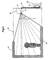
- Fig. 1 shows a front view of an indoor unit 10 of an air conditioner according to Embodiment 1.
- the indoor unit 10 includes a receiving unit 15 at the upper right of an air outlet 12 which is at the front bottom of the indoor unit 10 and which blows conditioned air (air cooled/heated/dehumidified/etc by an indoor heat exchanger not shown).
- the receiving unit 15 receives an infrared signal from a transmitting unit (not shown) of a remote control device (not shown).
- a transmitting unit 16 is provided at the upper right of the air outlet 12 which discharges conditioned air.
- a plug 18 for the indoor unit 10 which is supplied with a power source (commercial power supply (50/60 Hz)) from a socket in the room.
- a cable 40 for receiving and transmitting information and control between the indoor unit 10 and an outdoor unit 20 to be described later is connected to a predetermined position at the back of the indoor unit 10.
- the cable 40 is connected to the left corner of the indoor unit 10 seen from the back.
- An indoor temperature sensor 13 (an indoor air temperature detection unit) for measuring a temperature of indoor air and a humidity sensor (not shown) for measuring a humidity of indoor air are provided, for example, near an air inlet 11 for sucking indoor air or at a point of wind flow which is generated by forming an opening in the side of the indoor unit.
- thermopile type infrared sensor 14 which can measure radiant heat emitted by the floor or the wall, and a temperature of a person.
- a pipe temperature sensor which measures a pipe temperature is provided in the indoor heat exchanger.
- an indoor microcomputer which is built in the control device for controlling operations of the air conditioner is stored in an electrical parts box (not shown) of the indoor unit 10, for example.
- programs relating to controlling are stored in the indoor microcomputer.
- a blower device is mounted in the indoor unit 10 of the air conditioner so that indoor air sucked from the air inlet 11 may be transmitted in order through an air filter, an indoor heat exchanger (plate-fin type) and the air outlet 12, and further, conditioned air may be transmitted into the inside of the room by a louver plate 17.
- the blower device indicates a cross flow fan, an axial blower, a sirocco fan, etc. and a motor for driving them.
- Fig. 2 shows an exploded perspective view of the outdoor unit 20 of the air conditioner according to Embodiment 1.
- an outdoor microcomputer in the electrical parts box of the outdoor unit 20, for example.
- the outdoor microcomputer is built in an outdoor control device 21 which controls operations of the air conditioner.
- an outdoor temperature sensor 23 which measures an outdoor air temperature is built in the outdoor unit 20.
- a thermistor is used as the outdoor temperature sensor 23.
- a compressor 22, a heat exchanger 24 (plate-fin type), a pressure reducing device (electronic expansion valve), a four-way valve, etc., which form a refrigerating cycle, are mounted in the outdoor unit 20.
- the compressor 22, which compresses a refrigerant, is such as a rotary compressor, a scroll compressor, or a reciprocating compressor.
- a blower 25 for performing ventilation is provided in the heat exchanger 24.
- An axial blower serves as the blower 25.
- Fig. 3 shows a sectional view depicting a positional relation between an indoor space 30 to be air-conditioned by the air conditioner and the air conditioner (the indoor unit 10 and the outdoor unit 20) according to Embodiment 1.
- the indoor unit 10 is installed on the upper wall in the indoor space and the outdoor unit 20 is installed outside.
- the indoor unit 10 and the outdoor unit 20 are connected by the cable 40 for receiving and transmitting information and control and by a refrigerant pipe (not shown) for connecting the indoor heat exchanger and the outdoor heat exchanger.
- the indoor unit 10 installed in the indoor space 30 includes the indoor temperature sensor 13 which measures a temperature of the indoor air, a humidity sensor (not shown) which measures a humidity of the indoor air, and the thermopile type infrared sensor 14 which can detect a temperature of a point distant from the indoor unit 10.
- the thermopile type infrared sensor 14 includes a plurality of elements arranged perpendicularly, and thus can measure temperatures of a plurality of ranges divided from a detection range X.
- thermopile type infrared sensor 14 can detect temperatures of the floor and wall, and near the ceiling (a floor and wall temperature C 32, and a ceiling ambient temperature Ta 31).
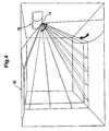
- Fig. 4 shows a perspective view depicting a relation between the indoor space 30 to be air-conditioned by the air conditioner and a sensing area of the air conditioner according to Embodiment 1.
- thermopile type infrared sensor 14 by rotating the thermopile type infrared sensor 14 about the axis in the vertical direction of the indoor unit 10, temperatures in the right to left direction can be detected.
- temperatures in the right to left direction can be detected.
- thermopile type infrared sensor 14 can measure not only a floor and wall temperature and a ceiling ambient temperature but also a skin temperature of a person. Then, when measuring temperatures in the indoor space 30 by using a plurality of elements arranged perpendicularly and pseudo elements obtained by rotating the perpendicular ones, if a certain point having a higher temperature than the surrounding temperatures is detected, this point can be determined as a place where a person is present.
- Fig. 5 shows a flowchart of a heating operation of the air conditioner according to Embodiment 1.
- a user determines a preset temperature A of the indoor space by using an operation content setting means, such as a remote control device (not shown), and transmits it to the indoor unit 10 in order to start the operation.
- an operation content setting means such as a remote control device (not shown)
- the preset temperature A is 24°C.
- the indoor unit 10 turns the louver plate 17 upward (at S11) so that the conditioned air blown from the air outlet 12 may be at the ceiling side and higher than the horizontal plane of the air outlet 12, and detects an indoor temperature of the indoor space 30 by the indoor temperature sensor 13, and a temperature of the floor and wall by the thermopile type infrared sensor 14 (at S12).
- the indoor microcomputer provided in the indoor control device calculates a body-sensory temperature B felt by the user, based on the indoor temperature, the floor temperature, and the wall temperature detected by the indoor temperature sensor 13 and the thermopile type infrared sensor 14. (For example, the calculated body-sensory temperature is 7 °C.)
- the indoor unit 10 transmits received information (heating mode data, and data on a difference between the body-sensory temperature B and the preset temperature A) to the outdoor control device 21 through the cable 40. Then, the compressor 22 performs operation at the optimum frequency, which quickly makes the indoor temperature approach the preset temperature A in the heating mode, based on the instruction of the outdoor microcomputer.
- louver plate 17 is turned downward and the air volume of the blower device is increased immediately after starting the operation of the compressor 22, since the indoor heat exchanger has not been sufficiently warmed up, a cold conditioned air may make the user feel uncomfortable.
- a pipe temperature thermistor (not shown), which measures a temperature ⁇ °C of the indoor heat exchanger, becomes a threshold value ⁇ °C of the pipe temperature
- the operation of the blower device is kept stopped or light wind operation is kept performed (for example, the threshold value ⁇ of the pipe temperature is 40°C). That is, in the case of ⁇ °C ⁇ a°C at the step S15, ⁇ being the temperature of the indoor heat exchanger and ⁇ being the threshold value of the pipe temperature, it returns to prior to the step S 15, and the operation of the blower device is stopped or light wind operation is performed.
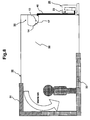
- the heating operation of the indoor space 30 is performed such that the louver plate 17 is turned downward as shown in Fig. 6 and the air volume of the blower device is increased in order to let a blown-off air 33 reach the user's feet (at S16).
- the air conditioner performs the heating operation while varying the frequency of the compressor 22 so that the indoor temperature may be the preset temperature A °C.
- controlling is performed only based on an indoor temperature sensor included in the indoor unit installed near the ceiling. Therefore, there has been a case where the indoor control device mistakes that it has reached a preset temperature A °C because of the warmth having a tendency to accumulate near the ceiling though the temperature of the place where the user is located is low, which easily occurs especially at the time of other heating apparatus being used in combination.
- the heating operation cannot make the user feel warm since the temperature of the place where the user is located is low. Then, the user may further raise the preset temperature to make air around the user warm, which leads the user to non energy saving.
- Fig. 6 shows a sectional view of the indoor space 30 to be air-conditioned by the air conditioner and a wind direction in a heating operation according to Embodiment 1. Since the indoor unit 10 of the air conditioner provided with the thermopile type infrared sensor 14 can detect a floor and wall temperature C 32, the place where the user is located can be sufficiently warmed as shown in Fig. 6 .
- the indoor temperature sensor 13 detects an indoor temperature
- the thermopile type infrared sensor 14 detects a floor and wall temperature and a ceiling ambient temperature in the indoor space 30 (the floor and wall temperature C 32 and the ceiling ambient temperature Ta 31). Based on these detected results, a body-sensory temperature B °C is calculated, and then, a difference between the body-sensory temperature B °C and the preset temperature A °C is calculated in order to control the air conditioner.
- the indoor control device transmits that the indoor space has reached the preset-temperature A °C to the outdoor control device 21 of the outdoor unit.
- the outdoor control device 21 judges that the indoor space 30 has reached the preset temperature A °C set by the user and has become a stable temperature, and then stops the operation of the compressor 22 (at S18).
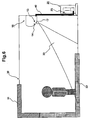
- Fig. 7 shows a sectional view of the indoor space 30 to be air-conditioned by the air conditioner and a wind direction at the time of reaching the preset temperature in a heating operation according to Embodiment 1.
- the louver plate 17 of the indoor unit 10 is turned upward to be the ceiling side and higher than the horizontal plane of the air outlet 12, and the blower device provided in the indoor unit 10 performs light wind operation or stops performing the operation in order not to make the user feel a chilly wind caused by a blown-off air 34 (at S 19).
- thermopile type infrared sensor 14 Even when the indoor space has reached the preset temperature A °C and the blower device performs light wind operation or stops performing the operation, an indoor temperature is detected by the indoor temperature sensor 13, temperatures in the detection range X are perpendicularly detected by the thermopile type infrared sensor 14, and temperatures in the right to left direction are detected by rotating the thermopile type infrared sensor 14 about the axis in the vertical direction of the indoor unit 10. Thus, the floor and wall temperature C 32 and the ceiling ambient temperature Ta 31 are detected.
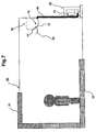
- Fig. 8 shows a sectional view of the indoor space 30 to be air-conditioned by the air conditioner and a wind direction in circulator operation according to Embodiment 1. Based on the detected results, a body-sensory temperature B °C is calculated similarly to the operation time.
- the preset temperature A and the body-sensory temperature B are compared (at S21). If the comparison result is: the preset temperature A ⁇ the body-sensory temperature B, the indoor unit 10 starts circulator operation of increasing the air volume of a blown-off air 35 by the blower device provided in the indoor unit 10 and moving the warm air accumulating overhead (near the ceiling) to the floor while keeping the louver plate 17 upward as shown in Fig. 8 (at S22).
- the indoor unit 10 is performing quiet operation, namely light wind operation is being performed or operation is stopped (at S19). Therefore, when performing circulator operation, it is aimed to suppress a rapid noise increase by keeping the air volume to have a noise level of 40 dBA or less which is generally regarded as a level of a library or a quiet residential section in the daytime.
- This noise level indicates a noise at a point located 0.8 m perpendicularly downward from the center of the indoor unit 10 and 1 m horizontally from it.
- Fig. 9 shows a flowchart of operations according to Embodiment 2.
- the point different from Embodiment 1 is that one condition for performing circulator operation is added as OR condition.
- This added condition is that circulator operation is to be started when the number of times Z becomes greater than or equal to a threshold value ⁇ , wherein Z indicates the number of times per hour of stopping the compressor 22 because a body sensory temperature B has reached a preset temperature A.
- the outdoor control device 21 receives the instruction from the indoor control device, judges that the air temperature of the indoor space 30 has reached the preset temperature A °C set by the user and has become a stable temperature, and stops the operation of the compressor 22. Then, at S24, Z being the number of times of stopping the compressor 22 is counted and stored in the indoor control device or the outdoor control device 21. This step of counting and storing Z being the number of times of stopping the compressor 22 is defined to be a compressor-stopping-times counting unit.
- the louver plate 17 of the indoor unit 10 is turned upward to be the ceiling side and higher than the horizontal plane of the air outlet 12 as shown in Fig. 7 , and the blower device provided in the indoor unit 10 performs light wind operation or stops performing the operation in order not to make the user feel a chilly wind caused by the blown-off air 34.
- Embodiment 1 even when the indoor space has reached the preset temperature A °C and the blower device performs light wind operation or stops performing the operation, an indoor temperature is detected by the indoor temperature sensor 13, temperatures in the detection range X are perpendicularly detected by the thermopile type infrared sensor 14, and temperatures in the right to left direction are detected by rotating the thermopile type infrared sensor 14 about the axis in the vertical direction of the indoor unit 10.
- the floor and wall temperature C 32 and the ceiling ambient temperature Ta 31 are detected.
- the indoor unit 10 starts circulator operation of increasing the
- This added condition is that circulator operation is to be started when the number of times Z becomes greater than or equal to a threshold value ⁇ , wherein Z indicates the number of times per hour of stopping the compressor 22 because a body-sensory temperature B has reached a preset temperature A.
- Z indicates the number of times per hour of stopping the compressor 22 because a body-sensory temperature B has reached a preset temperature A.
- the mode of stopping the compressor 22 is frequently turned on, and warm air tends to easily accumulate near the ceiling when compared with the single operation by the air conditioner.
- the indoor unit 10 is performing quiet operation, namely light wind operation is being performed or operation is stopped. Therefore, when performing circulator operation, it is aimed to suppress a rapid noise increase by keeping the air volume to have a noise level of 40 dBA or less which is generally regarded as a level of a library or a quiet residential section in the daytime.
- thermopile type infrared sensor 14 By adding the condition that circulator operation is to be started when the number of times Z indicating the number of times of stopping the compressor 22 becomes greater than or equal to the threshold value ⁇ , it becomes possible to obtain a certain level effect, even in the case of failure of the thermopile type infrared sensor 14 or in the case of incapable of measuring a ceiling ambient temperature Ta 31 because of some obstruction in the detection range, or alternatively, even in the case of a model with no thermopile type infrared sensor 14.
- thermopile type infrared sensor 14 performs sensing of the entire indoor space 30 and a comparison result between a ceiling ambient temperature Ta 31 and a body-sensory temperature B or a floor and wall temperature C 32 of the place where the user is located becomes greater than or equal to a threshold value ⁇ .
Applications Claiming Priority (1)
| Application Number | Priority Date | Filing Date | Title |
|---|---|---|---|
| JP2010161219A JP5289392B2 (ja) | 2010-07-16 | 2010-07-16 | 空気調和機 |
Publications (3)
| Publication Number | Publication Date |
|---|---|
| EP2407728A2 true EP2407728A2 (fr) | 2012-01-18 |
| EP2407728A3 EP2407728A3 (fr) | 2018-04-18 |
| EP2407728B1 EP2407728B1 (fr) | 2021-11-03 |
Family
ID=44906743
Family Applications (1)
| Application Number | Title | Priority Date | Filing Date |
|---|---|---|---|
| EP11003079.8A Active EP2407728B1 (fr) | 2010-07-16 | 2011-04-12 | Climatiseur |
Country Status (5)
| Country | Link |
|---|---|
| US (1) | US8826678B2 (fr) |
| EP (1) | EP2407728B1 (fr) |
| JP (1) | JP5289392B2 (fr) |
| CN (1) | CN102338446B (fr) |
| ES (1) | ES2898366T3 (fr) |
Cited By (5)
| Publication number | Priority date | Publication date | Assignee | Title |
|---|---|---|---|---|
| CN104110783A (zh) * | 2013-12-20 | 2014-10-22 | 广东美的制冷设备有限公司 | 智能空调控制方法、控制装置和智能空调器 |
| CN105276772A (zh) * | 2015-11-30 | 2016-01-27 | 惠州学院 | 空调控制方法及智能空调 |
| CN107435975A (zh) * | 2017-07-14 | 2017-12-05 | 深圳市盛路物联通讯技术有限公司 | 设备处理方法及相关产品 |
| EP3396263A1 (fr) * | 2017-04-18 | 2018-10-31 | Caverion Suomi Oy | Unité multicapteur, agencement et procédé permettant de gérer les conditions climatiques intérieures d'une pièce ou d'une zone |
| EP3441688A4 (fr) * | 2016-04-05 | 2019-04-24 | Mitsubishi Electric Corporation | Unité intérieure pour climatiseur |
Families Citing this family (33)
| Publication number | Priority date | Publication date | Assignee | Title |
|---|---|---|---|---|
| WO2012101831A1 (fr) * | 2011-01-28 | 2012-08-02 | 三菱電機株式会社 | Système et méthode de climatisation |
| US10371399B1 (en) * | 2012-03-15 | 2019-08-06 | Carlos Rodriguez | Smart vents and systems and methods for operating an air conditioning system including such vents |
| JP5930909B2 (ja) * | 2012-08-01 | 2016-06-08 | 三菱電機株式会社 | 空気調和機 |
| JP5754429B2 (ja) * | 2012-09-13 | 2015-07-29 | ダイキン工業株式会社 | 空調室内機 |
| JP6056297B2 (ja) * | 2012-09-13 | 2017-01-11 | ダイキン工業株式会社 | 空調室内機 |
| US9864730B2 (en) * | 2012-11-05 | 2018-01-09 | Qualcomm Incorporated | Thermal aware headphones |
| US10001789B2 (en) * | 2013-01-03 | 2018-06-19 | Robert Hunka | Multifuncional environmental control unit |
| JP6091243B2 (ja) * | 2013-02-18 | 2017-03-08 | 三菱電機株式会社 | 空気調和機 |
| JP2015152192A (ja) * | 2014-02-12 | 2015-08-24 | 三菱電機株式会社 | 空気調和システム |
| US20150323210A1 (en) * | 2014-05-07 | 2015-11-12 | Lennox Industries Inc. | Uniform temperature distribution in space using a fluid mixing device |
| JP6253774B2 (ja) * | 2014-06-09 | 2017-12-27 | 三菱電機株式会社 | 空気調和システム |
| JP6242300B2 (ja) * | 2014-06-25 | 2017-12-06 | 三菱電機株式会社 | 空気調和装置の室内機及び空気調和装置 |
| JP6173269B2 (ja) * | 2014-07-25 | 2017-08-02 | 三菱電機株式会社 | 通信機器および空気調和機 |
| JP6129126B2 (ja) * | 2014-08-04 | 2017-05-17 | 三菱電機株式会社 | 空気調和機の室内機 |
| JP2016038135A (ja) * | 2014-08-06 | 2016-03-22 | 三菱電機株式会社 | 空気調和機 |
| JP6344213B2 (ja) * | 2014-11-21 | 2018-06-20 | 三菱電機株式会社 | 空気清浄機 |
| MX2017008228A (es) * | 2014-12-24 | 2017-10-06 | Koninklijke Philips Nv | Arreglo y metodo de manejo de aire de una habitacion. |
| WO2016157384A1 (fr) * | 2015-03-30 | 2016-10-06 | 三菱電機株式会社 | Système de soufflage d'air |
| CN106338105B (zh) * | 2015-07-08 | 2020-04-10 | 松下知识产权经营株式会社 | 吸气装置以及吸气方法 |
| JP6540336B2 (ja) * | 2015-07-31 | 2019-07-10 | 株式会社富士通ゼネラル | 空気調和機 |
| EP3309470A4 (fr) * | 2016-08-09 | 2018-06-06 | Mitsubishi Electric Corporation | Dispositif de climatisation |
| CN106247686B (zh) * | 2016-08-16 | 2019-03-08 | 广东美的暖通设备有限公司 | 空调器的回油控制方法、回油控制装置和空调器 |
| EP3608599B1 (fr) * | 2017-04-07 | 2023-12-06 | Mitsubishi Electric Corporation | Climatiseur |
| CN107388475B (zh) * | 2017-06-07 | 2018-12-07 | 珠海格力电器股份有限公司 | 地板式空调的控制方法、装置和系统 |
| CN108332367A (zh) * | 2017-12-22 | 2018-07-27 | 珠海格力电器股份有限公司 | 空调送风控制方法及装置 |
| CN110285538A (zh) * | 2019-06-27 | 2019-09-27 | 广东美的制冷设备有限公司 | 空调器及其控制方法和计算机可读存储介质 |
| DE112020006516T5 (de) * | 2020-01-14 | 2022-12-01 | Mitsubishi Electric Corporation | Klimaanlage |
| JP7374005B2 (ja) | 2020-01-28 | 2023-11-06 | 三菱電機株式会社 | 送風システム |
| JP7414956B2 (ja) | 2020-03-09 | 2024-01-16 | 三菱電機株式会社 | 空調システム、空調制御装置、空調方法及びプログラム |
| CN111854319A (zh) * | 2020-07-27 | 2020-10-30 | 合肥美菱物联科技有限公司 | 一种可移动的热电堆传感器的冰箱控制系统和应用方法 |
| US20230243540A1 (en) | 2020-09-08 | 2023-08-03 | Mitsubishi Electric Corporation | Air-conditioning system |
| CN112682918B (zh) * | 2020-12-14 | 2022-04-29 | 珠海格力电器股份有限公司 | 空调送风系统的使用方法 |
| CN112944622B (zh) * | 2021-02-26 | 2022-07-05 | 青岛海尔空调器有限总公司 | 一种下出风空调的控制方法和下出风空调 |
Citations (1)
| Publication number | Priority date | Publication date | Assignee | Title |
|---|---|---|---|---|
| JP2007322062A (ja) | 2006-05-31 | 2007-12-13 | Daikin Ind Ltd | 空気調和装置 |
Family Cites Families (17)
| Publication number | Priority date | Publication date | Assignee | Title |
|---|---|---|---|---|
| JPH0526508A (ja) | 1991-07-16 | 1993-02-02 | Matsushita Refrig Co Ltd | 空気調和機 |
| US5477698A (en) * | 1992-06-16 | 1995-12-26 | Matsushita Electric Industrial Co. Ltd. | Air conditioner |
| US5326028A (en) * | 1992-08-24 | 1994-07-05 | Sanyo Electric Co., Ltd. | System for detecting indoor conditions and air conditioner incorporating same |
| JP3137042B2 (ja) | 1997-08-08 | 2001-02-19 | ダイキン工業株式会社 | 空気調和機の室内機の気流制御方法および気流制御装置 |
| JP4000673B2 (ja) | 1998-06-22 | 2007-10-31 | 松下電器産業株式会社 | 温風暖房機 |
| JP2001208394A (ja) * | 2000-01-31 | 2001-08-03 | Mitsubishi Electric Corp | 空気調和システム |
| JP2001221489A (ja) * | 2000-02-07 | 2001-08-17 | Sanyo Electric Co Ltd | 室内空気循環機能付き換気装置 |
| JP2002061925A (ja) * | 2000-08-23 | 2002-02-28 | Daikin Ind Ltd | 空気調和装置 |
| JP3975853B2 (ja) * | 2002-07-30 | 2007-09-12 | 三菱電機株式会社 | 空気調和機 |
| US20050034749A1 (en) * | 2003-08-12 | 2005-02-17 | Chung-Nan Chen | Structure of thermopile sensor |
| JP4434998B2 (ja) * | 2005-03-09 | 2010-03-17 | 辻川 俊弘 | 室内温度制御システム |
| JP2007085606A (ja) | 2005-09-21 | 2007-04-05 | Matsushita Electric Ind Co Ltd | 空気調和機 |
| US7849121B2 (en) * | 2006-04-20 | 2010-12-07 | Hewlett-Packard Development Company, L.P. | Optical-based, self-authenticating quantum random number generators |
| JP4749352B2 (ja) | 2007-01-30 | 2011-08-17 | シャープ株式会社 | 空気調和機 |
| JP2009257700A (ja) * | 2008-04-18 | 2009-11-05 | Panasonic Electric Works Co Ltd | 天井暖房装置 |
| JP5063509B2 (ja) * | 2008-06-30 | 2012-10-31 | 三菱電機株式会社 | 空気調和機 |
| JP5111445B2 (ja) * | 2008-09-10 | 2013-01-09 | 三菱電機株式会社 | 空気調和機 |
-
2010
- 2010-07-16 JP JP2010161219A patent/JP5289392B2/ja active Active
-
2011
- 2011-04-12 ES ES11003079T patent/ES2898366T3/es active Active
- 2011-04-12 EP EP11003079.8A patent/EP2407728B1/fr active Active
- 2011-04-15 US US13/087,445 patent/US8826678B2/en active Active
- 2011-04-15 CN CN201110094322.3A patent/CN102338446B/zh active Active
Patent Citations (1)
| Publication number | Priority date | Publication date | Assignee | Title |
|---|---|---|---|---|
| JP2007322062A (ja) | 2006-05-31 | 2007-12-13 | Daikin Ind Ltd | 空気調和装置 |
Cited By (8)
| Publication number | Priority date | Publication date | Assignee | Title |
|---|---|---|---|---|
| CN104110783A (zh) * | 2013-12-20 | 2014-10-22 | 广东美的制冷设备有限公司 | 智能空调控制方法、控制装置和智能空调器 |
| CN105276772A (zh) * | 2015-11-30 | 2016-01-27 | 惠州学院 | 空调控制方法及智能空调 |
| CN105276772B (zh) * | 2015-11-30 | 2018-08-03 | 惠州学院 | 空调控制方法及智能空调 |
| EP3441688A4 (fr) * | 2016-04-05 | 2019-04-24 | Mitsubishi Electric Corporation | Unité intérieure pour climatiseur |
| EP3396263A1 (fr) * | 2017-04-18 | 2018-10-31 | Caverion Suomi Oy | Unité multicapteur, agencement et procédé permettant de gérer les conditions climatiques intérieures d'une pièce ou d'une zone |
| CN107435975A (zh) * | 2017-07-14 | 2017-12-05 | 深圳市盛路物联通讯技术有限公司 | 设备处理方法及相关产品 |
| WO2019010789A1 (fr) * | 2017-07-14 | 2019-01-17 | 深圳市盛路物联通讯技术有限公司 | Procédé de traitement de dispositif et produits associés |
| CN107435975B (zh) * | 2017-07-14 | 2020-02-18 | 深圳市盛路物联通讯技术有限公司 | 设备处理方法及相关产品 |
Also Published As
| Publication number | Publication date |
|---|---|
| CN102338446B (zh) | 2014-08-27 |
| JP2012021735A (ja) | 2012-02-02 |
| CN102338446A (zh) | 2012-02-01 |
| JP5289392B2 (ja) | 2013-09-11 |
| EP2407728B1 (fr) | 2021-11-03 |
| US20120012297A1 (en) | 2012-01-19 |
| US8826678B2 (en) | 2014-09-09 |
| ES2898366T3 (es) | 2022-03-07 |
| EP2407728A3 (fr) | 2018-04-18 |
Similar Documents
| Publication | Publication Date | Title |
|---|---|---|
| US8826678B2 (en) | Air conditioner | |
| JP5932998B2 (ja) | 空気調和システム | |
| JP6072561B2 (ja) | 空気調和システム | |
| JP4478082B2 (ja) | 空気調和機の制御方法 | |
| JP5749612B2 (ja) | 室内環境調整システム | |
| CN110878981B (zh) | 空调器及其控制方法 | |
| JP6301634B2 (ja) | 空気調和機 | |
| JP6250076B2 (ja) | 空調制御装置、空調制御システム、空調制御方法及びプログラム | |
| EP2719963B1 (fr) | Système et procédé de réglage de température, contrôleur de système et programme | |
| US10551082B2 (en) | Air-conditioning device | |
| GB2527193A (en) | Indoor unit and air conditioning apparatus | |
| JP2009092252A (ja) | 空気調和機 | |
| JP2016038135A (ja) | 空気調和機 | |
| JP2004150679A (ja) | 空気調和システム | |
| JP2007024416A (ja) | 空気調和機 | |
| JP5930909B2 (ja) | 空気調和機 | |
| JP2016121857A (ja) | 空気調和機 | |
| JP6537705B2 (ja) | 制御装置、空調システム、空調方法及びプログラム | |
| US10837670B2 (en) | Air-conditioning apparatus | |
| JP4983883B2 (ja) | 空気調和機 | |
| JP6479736B2 (ja) | 空気調和機 | |
| AU2015334400A1 (en) | Air conditioning apparatus | |
| WO2021192263A1 (fr) | Système de ventilation et de climatisation | |
| KR20140136194A (ko) | 공기조화 시스템 및 그 제어방법 | |
| WO2021192262A1 (fr) | Système de climatisation/ventilation |
Legal Events
| Date | Code | Title | Description |
|---|---|---|---|
| AK | Designated contracting states |
Kind code of ref document: A2 Designated state(s): AL AT BE BG CH CY CZ DE DK EE ES FI FR GB GR HR HU IE IS IT LI LT LU LV MC MK MT NL NO PL PT RO RS SE SI SK SM TR |
|
| AX | Request for extension of the european patent |
Extension state: BA ME |
|
| PUAI | Public reference made under article 153(3) epc to a published international application that has entered the european phase |
Free format text: ORIGINAL CODE: 0009012 |
|
| PUAL | Search report despatched |
Free format text: ORIGINAL CODE: 0009013 |
|
| AK | Designated contracting states |
Kind code of ref document: A3 Designated state(s): AL AT BE BG CH CY CZ DE DK EE ES FI FR GB GR HR HU IE IS IT LI LT LU LV MC MK MT NL NO PL PT RO RS SE SI SK SM TR |
|
| AX | Request for extension of the european patent |
Extension state: BA ME |
|
| RIC1 | Information provided on ipc code assigned before grant |
Ipc: F24F 11/00 20060101AFI20180309BHEP |
|
| STAA | Information on the status of an ep patent application or granted ep patent |
Free format text: STATUS: REQUEST FOR EXAMINATION WAS MADE |
|
| 17P | Request for examination filed |
Effective date: 20180928 |
|
| RBV | Designated contracting states (corrected) |
Designated state(s): AL AT BE BG CH CY CZ DE DK EE ES FI FR GB GR HR HU IE IS IT LI LT LU LV MC MK MT NL NO PL PT RO RS SE SI SK SM TR |
|
| STAA | Information on the status of an ep patent application or granted ep patent |
Free format text: STATUS: EXAMINATION IS IN PROGRESS |
|
| 17Q | First examination report despatched |
Effective date: 20190725 |
|
| STAA | Information on the status of an ep patent application or granted ep patent |
Free format text: STATUS: EXAMINATION IS IN PROGRESS |
|
| GRAP | Despatch of communication of intention to grant a patent |
Free format text: ORIGINAL CODE: EPIDOSNIGR1 |
|
| STAA | Information on the status of an ep patent application or granted ep patent |
Free format text: STATUS: GRANT OF PATENT IS INTENDED |
|
| INTG | Intention to grant announced |
Effective date: 20210518 |
|
| GRAS | Grant fee paid |
Free format text: ORIGINAL CODE: EPIDOSNIGR3 |
|
| GRAA | (expected) grant |
Free format text: ORIGINAL CODE: 0009210 |
|
| STAA | Information on the status of an ep patent application or granted ep patent |
Free format text: STATUS: THE PATENT HAS BEEN GRANTED |
|
| AK | Designated contracting states |
Kind code of ref document: B1 Designated state(s): AL AT BE BG CH CY CZ DE DK EE ES FI FR GB GR HR HU IE IS IT LI LT LU LV MC MK MT NL NO PL PT RO RS SE SI SK SM TR |
|
| REG | Reference to a national code |
Ref country code: GB Ref legal event code: FG4D |
|
| REG | Reference to a national code |
Ref country code: AT Ref legal event code: REF Ref document number: 1444288 Country of ref document: AT Kind code of ref document: T Effective date: 20211115 Ref country code: CH Ref legal event code: EP |
|
| REG | Reference to a national code |
Ref country code: DE Ref legal event code: R096 Ref document number: 602011072033 Country of ref document: DE |
|
| REG | Reference to a national code |
Ref country code: IE Ref legal event code: FG4D |
|
| REG | Reference to a national code |
Ref country code: LT Ref legal event code: MG9D |
|
| REG | Reference to a national code |
Ref country code: ES Ref legal event code: FG2A Ref document number: 2898366 Country of ref document: ES Kind code of ref document: T3 Effective date: 20220307 |
|
| REG | Reference to a national code |
Ref country code: NL Ref legal event code: MP Effective date: 20211103 |
|
| REG | Reference to a national code |
Ref country code: AT Ref legal event code: MK05 Ref document number: 1444288 Country of ref document: AT Kind code of ref document: T Effective date: 20211103 |
|
| PG25 | Lapsed in a contracting state [announced via postgrant information from national office to epo] |
Ref country code: RS Free format text: LAPSE BECAUSE OF FAILURE TO SUBMIT A TRANSLATION OF THE DESCRIPTION OR TO PAY THE FEE WITHIN THE PRESCRIBED TIME-LIMIT Effective date: 20211103 Ref country code: LT Free format text: LAPSE BECAUSE OF FAILURE TO SUBMIT A TRANSLATION OF THE DESCRIPTION OR TO PAY THE FEE WITHIN THE PRESCRIBED TIME-LIMIT Effective date: 20211103 Ref country code: FI Free format text: LAPSE BECAUSE OF FAILURE TO SUBMIT A TRANSLATION OF THE DESCRIPTION OR TO PAY THE FEE WITHIN THE PRESCRIBED TIME-LIMIT Effective date: 20211103 Ref country code: BG Free format text: LAPSE BECAUSE OF FAILURE TO SUBMIT A TRANSLATION OF THE DESCRIPTION OR TO PAY THE FEE WITHIN THE PRESCRIBED TIME-LIMIT Effective date: 20220203 Ref country code: AT Free format text: LAPSE BECAUSE OF FAILURE TO SUBMIT A TRANSLATION OF THE DESCRIPTION OR TO PAY THE FEE WITHIN THE PRESCRIBED TIME-LIMIT Effective date: 20211103 |
|
| PG25 | Lapsed in a contracting state [announced via postgrant information from national office to epo] |
Ref country code: IS Free format text: LAPSE BECAUSE OF FAILURE TO SUBMIT A TRANSLATION OF THE DESCRIPTION OR TO PAY THE FEE WITHIN THE PRESCRIBED TIME-LIMIT Effective date: 20220303 Ref country code: SE Free format text: LAPSE BECAUSE OF FAILURE TO SUBMIT A TRANSLATION OF THE DESCRIPTION OR TO PAY THE FEE WITHIN THE PRESCRIBED TIME-LIMIT Effective date: 20211103 Ref country code: PT Free format text: LAPSE BECAUSE OF FAILURE TO SUBMIT A TRANSLATION OF THE DESCRIPTION OR TO PAY THE FEE WITHIN THE PRESCRIBED TIME-LIMIT Effective date: 20220303 Ref country code: PL Free format text: LAPSE BECAUSE OF FAILURE TO SUBMIT A TRANSLATION OF THE DESCRIPTION OR TO PAY THE FEE WITHIN THE PRESCRIBED TIME-LIMIT Effective date: 20211103 Ref country code: NO Free format text: LAPSE BECAUSE OF FAILURE TO SUBMIT A TRANSLATION OF THE DESCRIPTION OR TO PAY THE FEE WITHIN THE PRESCRIBED TIME-LIMIT Effective date: 20220203 Ref country code: NL Free format text: LAPSE BECAUSE OF FAILURE TO SUBMIT A TRANSLATION OF THE DESCRIPTION OR TO PAY THE FEE WITHIN THE PRESCRIBED TIME-LIMIT Effective date: 20211103 Ref country code: LV Free format text: LAPSE BECAUSE OF FAILURE TO SUBMIT A TRANSLATION OF THE DESCRIPTION OR TO PAY THE FEE WITHIN THE PRESCRIBED TIME-LIMIT Effective date: 20211103 Ref country code: HR Free format text: LAPSE BECAUSE OF FAILURE TO SUBMIT A TRANSLATION OF THE DESCRIPTION OR TO PAY THE FEE WITHIN THE PRESCRIBED TIME-LIMIT Effective date: 20211103 Ref country code: GR Free format text: LAPSE BECAUSE OF FAILURE TO SUBMIT A TRANSLATION OF THE DESCRIPTION OR TO PAY THE FEE WITHIN THE PRESCRIBED TIME-LIMIT Effective date: 20220204 |
|
| PG25 | Lapsed in a contracting state [announced via postgrant information from national office to epo] |
Ref country code: SM Free format text: LAPSE BECAUSE OF FAILURE TO SUBMIT A TRANSLATION OF THE DESCRIPTION OR TO PAY THE FEE WITHIN THE PRESCRIBED TIME-LIMIT Effective date: 20211103 Ref country code: SK Free format text: LAPSE BECAUSE OF FAILURE TO SUBMIT A TRANSLATION OF THE DESCRIPTION OR TO PAY THE FEE WITHIN THE PRESCRIBED TIME-LIMIT Effective date: 20211103 Ref country code: RO Free format text: LAPSE BECAUSE OF FAILURE TO SUBMIT A TRANSLATION OF THE DESCRIPTION OR TO PAY THE FEE WITHIN THE PRESCRIBED TIME-LIMIT Effective date: 20211103 Ref country code: EE Free format text: LAPSE BECAUSE OF FAILURE TO SUBMIT A TRANSLATION OF THE DESCRIPTION OR TO PAY THE FEE WITHIN THE PRESCRIBED TIME-LIMIT Effective date: 20211103 Ref country code: DK Free format text: LAPSE BECAUSE OF FAILURE TO SUBMIT A TRANSLATION OF THE DESCRIPTION OR TO PAY THE FEE WITHIN THE PRESCRIBED TIME-LIMIT Effective date: 20211103 Ref country code: CZ Free format text: LAPSE BECAUSE OF FAILURE TO SUBMIT A TRANSLATION OF THE DESCRIPTION OR TO PAY THE FEE WITHIN THE PRESCRIBED TIME-LIMIT Effective date: 20211103 |
|
| REG | Reference to a national code |
Ref country code: DE Ref legal event code: R097 Ref document number: 602011072033 Country of ref document: DE |
|
| PLBE | No opposition filed within time limit |
Free format text: ORIGINAL CODE: 0009261 |
|
| STAA | Information on the status of an ep patent application or granted ep patent |
Free format text: STATUS: NO OPPOSITION FILED WITHIN TIME LIMIT |
|
| 26N | No opposition filed |
Effective date: 20220804 |
|
| PG25 | Lapsed in a contracting state [announced via postgrant information from national office to epo] |
Ref country code: AL Free format text: LAPSE BECAUSE OF FAILURE TO SUBMIT A TRANSLATION OF THE DESCRIPTION OR TO PAY THE FEE WITHIN THE PRESCRIBED TIME-LIMIT Effective date: 20211103 |
|
| REG | Reference to a national code |
Ref country code: DE Ref legal event code: R119 Ref document number: 602011072033 Country of ref document: DE |
|
| PG25 | Lapsed in a contracting state [announced via postgrant information from national office to epo] |
Ref country code: SI Free format text: LAPSE BECAUSE OF FAILURE TO SUBMIT A TRANSLATION OF THE DESCRIPTION OR TO PAY THE FEE WITHIN THE PRESCRIBED TIME-LIMIT Effective date: 20211103 |
|
| REG | Reference to a national code |
Ref country code: CH Ref legal event code: PL |
|
| GBPC | Gb: european patent ceased through non-payment of renewal fee |
Effective date: 20220412 |
|
| REG | Reference to a national code |
Ref country code: BE Ref legal event code: MM Effective date: 20220430 |
|
| PG25 | Lapsed in a contracting state [announced via postgrant information from national office to epo] |
Ref country code: MC Free format text: LAPSE BECAUSE OF FAILURE TO SUBMIT A TRANSLATION OF THE DESCRIPTION OR TO PAY THE FEE WITHIN THE PRESCRIBED TIME-LIMIT Effective date: 20211103 Ref country code: LU Free format text: LAPSE BECAUSE OF NON-PAYMENT OF DUE FEES Effective date: 20220412 Ref country code: LI Free format text: LAPSE BECAUSE OF NON-PAYMENT OF DUE FEES Effective date: 20220430 Ref country code: GB Free format text: LAPSE BECAUSE OF NON-PAYMENT OF DUE FEES Effective date: 20220412 Ref country code: DE Free format text: LAPSE BECAUSE OF NON-PAYMENT OF DUE FEES Effective date: 20221103 Ref country code: CH Free format text: LAPSE BECAUSE OF NON-PAYMENT OF DUE FEES Effective date: 20220430 |
|
| PG25 | Lapsed in a contracting state [announced via postgrant information from national office to epo] |
Ref country code: BE Free format text: LAPSE BECAUSE OF NON-PAYMENT OF DUE FEES Effective date: 20220430 |
|
| PG25 | Lapsed in a contracting state [announced via postgrant information from national office to epo] |
Ref country code: IE Free format text: LAPSE BECAUSE OF NON-PAYMENT OF DUE FEES Effective date: 20220412 |
|
| PGFP | Annual fee paid to national office [announced via postgrant information from national office to epo] |
Ref country code: FR Payment date: 20230309 Year of fee payment: 13 |
|
| PGFP | Annual fee paid to national office [announced via postgrant information from national office to epo] |
Ref country code: IT Payment date: 20230310 Year of fee payment: 13 |
|
| P01 | Opt-out of the competence of the unified patent court (upc) registered |
Effective date: 20230512 |
|
| PGFP | Annual fee paid to national office [announced via postgrant information from national office to epo] |
Ref country code: ES Payment date: 20230505 Year of fee payment: 13 |
|
| PG25 | Lapsed in a contracting state [announced via postgrant information from national office to epo] |
Ref country code: HU Free format text: LAPSE BECAUSE OF FAILURE TO SUBMIT A TRANSLATION OF THE DESCRIPTION OR TO PAY THE FEE WITHIN THE PRESCRIBED TIME-LIMIT; INVALID AB INITIO Effective date: 20110412 |
|
| PG25 | Lapsed in a contracting state [announced via postgrant information from national office to epo] |
Ref country code: MK Free format text: LAPSE BECAUSE OF FAILURE TO SUBMIT A TRANSLATION OF THE DESCRIPTION OR TO PAY THE FEE WITHIN THE PRESCRIBED TIME-LIMIT Effective date: 20211103 Ref country code: CY Free format text: LAPSE BECAUSE OF FAILURE TO SUBMIT A TRANSLATION OF THE DESCRIPTION OR TO PAY THE FEE WITHIN THE PRESCRIBED TIME-LIMIT Effective date: 20211103 |