EP2405028A2 - Procédé pour le traitement thermique de l'acier, procédé de production d'un composant mécanique et composant mécanique - Google Patents
Procédé pour le traitement thermique de l'acier, procédé de production d'un composant mécanique et composant mécanique Download PDFInfo
- Publication number
- EP2405028A2 EP2405028A2 EP11180367A EP11180367A EP2405028A2 EP 2405028 A2 EP2405028 A2 EP 2405028A2 EP 11180367 A EP11180367 A EP 11180367A EP 11180367 A EP11180367 A EP 11180367A EP 2405028 A2 EP2405028 A2 EP 2405028A2
- Authority
- EP
- European Patent Office
- Prior art keywords
- mass
- steel
- mechanical component
- heat treatment
- hardness
- Prior art date
- Legal status (The legal status is an assumption and is not a legal conclusion. Google has not performed a legal analysis and makes no representation as to the accuracy of the status listed.)
- Granted
Links
- 229910000831 Steel Inorganic materials 0.000 title claims abstract description 268
- 239000010959 steel Substances 0.000 title claims abstract description 268
- 238000010438 heat treatment Methods 0.000 title claims abstract description 115
- 238000000034 method Methods 0.000 title claims abstract description 106
- 238000009792 diffusion process Methods 0.000 claims abstract description 84
- 238000005121 nitriding Methods 0.000 claims abstract description 77
- VYZAMTAEIAYCRO-UHFFFAOYSA-N Chromium Chemical compound [Cr] VYZAMTAEIAYCRO-UHFFFAOYSA-N 0.000 claims abstract description 49
- 229910052804 chromium Inorganic materials 0.000 claims abstract description 49
- 239000011651 chromium Substances 0.000 claims abstract description 49
- XEEYBQQBJWHFJM-UHFFFAOYSA-N Iron Chemical compound [Fe] XEEYBQQBJWHFJM-UHFFFAOYSA-N 0.000 claims abstract description 44
- 229910052799 carbon Inorganic materials 0.000 claims abstract description 33
- PXHVJJICTQNCMI-UHFFFAOYSA-N Nickel Chemical compound [Ni] PXHVJJICTQNCMI-UHFFFAOYSA-N 0.000 claims abstract description 30
- OKTJSMMVPCPJKN-UHFFFAOYSA-N Carbon Chemical compound [C] OKTJSMMVPCPJKN-UHFFFAOYSA-N 0.000 claims abstract description 27
- 229910052720 vanadium Inorganic materials 0.000 claims abstract description 23
- 229910052742 iron Inorganic materials 0.000 claims abstract description 22
- 238000010791 quenching Methods 0.000 claims abstract description 18
- ZOKXTWBITQBERF-UHFFFAOYSA-N Molybdenum Chemical compound [Mo] ZOKXTWBITQBERF-UHFFFAOYSA-N 0.000 claims abstract description 15
- 239000012535 impurity Substances 0.000 claims abstract description 15
- WPBNNNQJVZRUHP-UHFFFAOYSA-L manganese(2+);methyl n-[[2-(methoxycarbonylcarbamothioylamino)phenyl]carbamothioyl]carbamate;n-[2-(sulfidocarbothioylamino)ethyl]carbamodithioate Chemical compound [Mn+2].[S-]C(=S)NCCNC([S-])=S.COC(=O)NC(=S)NC1=CC=CC=C1NC(=S)NC(=O)OC WPBNNNQJVZRUHP-UHFFFAOYSA-L 0.000 claims abstract description 15
- 229910052750 molybdenum Inorganic materials 0.000 claims abstract description 15
- 239000011733 molybdenum Substances 0.000 claims abstract description 15
- 229910052759 nickel Inorganic materials 0.000 claims abstract description 15
- 229910052710 silicon Inorganic materials 0.000 claims abstract description 15
- 239000010703 silicon Substances 0.000 claims abstract description 15
- LEONUFNNVUYDNQ-UHFFFAOYSA-N vanadium atom Chemical compound [V] LEONUFNNVUYDNQ-UHFFFAOYSA-N 0.000 claims abstract description 15
- 230000000171 quenching effect Effects 0.000 claims description 17
- 238000005255 carburizing Methods 0.000 claims description 8
- 239000002344 surface layer Substances 0.000 abstract description 92
- 239000002244 precipitate Substances 0.000 abstract description 60
- 229910000760 Hardened steel Inorganic materials 0.000 abstract description 3
- IJGRMHOSHXDMSA-UHFFFAOYSA-N Atomic nitrogen Chemical compound N#N IJGRMHOSHXDMSA-UHFFFAOYSA-N 0.000 description 104
- 229910052757 nitrogen Inorganic materials 0.000 description 48
- 238000005496 tempering Methods 0.000 description 27
- 239000010410 layer Substances 0.000 description 23
- 238000005096 rolling process Methods 0.000 description 19
- 230000000052 comparative effect Effects 0.000 description 18
- 238000002474 experimental method Methods 0.000 description 16
- 238000009826 distribution Methods 0.000 description 14
- 239000011159 matrix material Substances 0.000 description 14
- 230000015572 biosynthetic process Effects 0.000 description 12
- 239000007789 gas Substances 0.000 description 12
- VNWKTOKETHGBQD-UHFFFAOYSA-N methane Chemical compound C VNWKTOKETHGBQD-UHFFFAOYSA-N 0.000 description 12
- 150000004767 nitrides Chemical class 0.000 description 11
- 230000009466 transformation Effects 0.000 description 11
- 239000001257 hydrogen Substances 0.000 description 9
- 229910052739 hydrogen Inorganic materials 0.000 description 9
- UFHFLCQGNIYNRP-UHFFFAOYSA-N Hydrogen Chemical compound [H][H] UFHFLCQGNIYNRP-UHFFFAOYSA-N 0.000 description 6
- 230000035515 penetration Effects 0.000 description 6
- 229910001566 austenite Inorganic materials 0.000 description 5
- XKRFYHLGVUSROY-UHFFFAOYSA-N Argon Chemical compound [Ar] XKRFYHLGVUSROY-UHFFFAOYSA-N 0.000 description 4
- 238000010586 diagram Methods 0.000 description 4
- 229910000734 martensite Inorganic materials 0.000 description 4
- 238000000879 optical micrograph Methods 0.000 description 4
- 230000000149 penetrating effect Effects 0.000 description 4
- 238000005498 polishing Methods 0.000 description 4
- 239000000047 product Substances 0.000 description 4
- 229910017389 Fe3N Inorganic materials 0.000 description 3
- 229910000727 Fe4N Inorganic materials 0.000 description 3
- 238000001816 cooling Methods 0.000 description 3
- 150000002431 hydrogen Chemical class 0.000 description 3
- 239000007788 liquid Substances 0.000 description 3
- 238000004519 manufacturing process Methods 0.000 description 3
- 230000000717 retained effect Effects 0.000 description 3
- 238000005507 spraying Methods 0.000 description 3
- 230000000087 stabilizing effect Effects 0.000 description 3
- QGZKDVFQNNGYKY-UHFFFAOYSA-N Ammonia Chemical compound N QGZKDVFQNNGYKY-UHFFFAOYSA-N 0.000 description 2
- 229910052774 Proactinium Inorganic materials 0.000 description 2
- 229910052786 argon Inorganic materials 0.000 description 2
- 238000005520 cutting process Methods 0.000 description 2
- 238000005242 forging Methods 0.000 description 2
- 239000000463 material Substances 0.000 description 2
- 238000005259 measurement Methods 0.000 description 2
- 230000003287 optical effect Effects 0.000 description 2
- 239000007787 solid Substances 0.000 description 2
- 230000001131 transforming effect Effects 0.000 description 2
- 238000007514 turning Methods 0.000 description 2
- UGFAIRIUMAVXCW-UHFFFAOYSA-N Carbon monoxide Chemical compound [O+]#[C-] UGFAIRIUMAVXCW-UHFFFAOYSA-N 0.000 description 1
- 229910021529 ammonia Inorganic materials 0.000 description 1
- 229910002091 carbon monoxide Inorganic materials 0.000 description 1
- 230000000694 effects Effects 0.000 description 1
- 230000009191 jumping Effects 0.000 description 1
- 239000000203 mixture Substances 0.000 description 1
- 238000012986 modification Methods 0.000 description 1
- 230000004048 modification Effects 0.000 description 1
- 150000003839 salts Chemical class 0.000 description 1
- 238000010183 spectrum analysis Methods 0.000 description 1
- 229910000859 α-Fe Inorganic materials 0.000 description 1
Images


Classifications
-
- C—CHEMISTRY; METALLURGY
- C23—COATING METALLIC MATERIAL; COATING MATERIAL WITH METALLIC MATERIAL; CHEMICAL SURFACE TREATMENT; DIFFUSION TREATMENT OF METALLIC MATERIAL; COATING BY VACUUM EVAPORATION, BY SPUTTERING, BY ION IMPLANTATION OR BY CHEMICAL VAPOUR DEPOSITION, IN GENERAL; INHIBITING CORROSION OF METALLIC MATERIAL OR INCRUSTATION IN GENERAL
- C23C—COATING METALLIC MATERIAL; COATING MATERIAL WITH METALLIC MATERIAL; SURFACE TREATMENT OF METALLIC MATERIAL BY DIFFUSION INTO THE SURFACE, BY CHEMICAL CONVERSION OR SUBSTITUTION; COATING BY VACUUM EVAPORATION, BY SPUTTERING, BY ION IMPLANTATION OR BY CHEMICAL VAPOUR DEPOSITION, IN GENERAL
- C23C8/00—Solid state diffusion of only non-metal elements into metallic material surfaces; Chemical surface treatment of metallic material by reaction of the surface with a reactive gas, leaving reaction products of surface material in the coating, e.g. conversion coatings, passivation of metals
- C23C8/06—Solid state diffusion of only non-metal elements into metallic material surfaces; Chemical surface treatment of metallic material by reaction of the surface with a reactive gas, leaving reaction products of surface material in the coating, e.g. conversion coatings, passivation of metals using gases
- C23C8/36—Solid state diffusion of only non-metal elements into metallic material surfaces; Chemical surface treatment of metallic material by reaction of the surface with a reactive gas, leaving reaction products of surface material in the coating, e.g. conversion coatings, passivation of metals using gases using ionised gases, e.g. ionitriding
- C23C8/38—Treatment of ferrous surfaces
-
- C—CHEMISTRY; METALLURGY
- C21—METALLURGY OF IRON
- C21D—MODIFYING THE PHYSICAL STRUCTURE OF FERROUS METALS; GENERAL DEVICES FOR HEAT TREATMENT OF FERROUS OR NON-FERROUS METALS OR ALLOYS; MAKING METAL MALLEABLE, e.g. BY DECARBURISATION OR TEMPERING
- C21D1/00—General methods or devices for heat treatment, e.g. annealing, hardening, quenching or tempering
- C21D1/06—Surface hardening
- C21D1/09—Surface hardening by direct application of electrical or wave energy; by particle radiation
-
- C—CHEMISTRY; METALLURGY
- C21—METALLURGY OF IRON
- C21D—MODIFYING THE PHYSICAL STRUCTURE OF FERROUS METALS; GENERAL DEVICES FOR HEAT TREATMENT OF FERROUS OR NON-FERROUS METALS OR ALLOYS; MAKING METAL MALLEABLE, e.g. BY DECARBURISATION OR TEMPERING
- C21D1/00—General methods or devices for heat treatment, e.g. annealing, hardening, quenching or tempering
- C21D1/18—Hardening; Quenching with or without subsequent tempering
- C21D1/25—Hardening, combined with annealing between 300 degrees Celsius and 600 degrees Celsius, i.e. heat refining ("Vergüten")
-
- C—CHEMISTRY; METALLURGY
- C21—METALLURGY OF IRON
- C21D—MODIFYING THE PHYSICAL STRUCTURE OF FERROUS METALS; GENERAL DEVICES FOR HEAT TREATMENT OF FERROUS OR NON-FERROUS METALS OR ALLOYS; MAKING METAL MALLEABLE, e.g. BY DECARBURISATION OR TEMPERING
- C21D1/00—General methods or devices for heat treatment, e.g. annealing, hardening, quenching or tempering
- C21D1/78—Combined heat-treatments not provided for above
-
- C—CHEMISTRY; METALLURGY
- C21—METALLURGY OF IRON
- C21D—MODIFYING THE PHYSICAL STRUCTURE OF FERROUS METALS; GENERAL DEVICES FOR HEAT TREATMENT OF FERROUS OR NON-FERROUS METALS OR ALLOYS; MAKING METAL MALLEABLE, e.g. BY DECARBURISATION OR TEMPERING
- C21D6/00—Heat treatment of ferrous alloys
- C21D6/002—Heat treatment of ferrous alloys containing Cr
-
- C—CHEMISTRY; METALLURGY
- C21—METALLURGY OF IRON
- C21D—MODIFYING THE PHYSICAL STRUCTURE OF FERROUS METALS; GENERAL DEVICES FOR HEAT TREATMENT OF FERROUS OR NON-FERROUS METALS OR ALLOYS; MAKING METAL MALLEABLE, e.g. BY DECARBURISATION OR TEMPERING
- C21D6/00—Heat treatment of ferrous alloys
- C21D6/004—Heat treatment of ferrous alloys containing Cr and Ni
-
- C—CHEMISTRY; METALLURGY
- C21—METALLURGY OF IRON
- C21D—MODIFYING THE PHYSICAL STRUCTURE OF FERROUS METALS; GENERAL DEVICES FOR HEAT TREATMENT OF FERROUS OR NON-FERROUS METALS OR ALLOYS; MAKING METAL MALLEABLE, e.g. BY DECARBURISATION OR TEMPERING
- C21D6/00—Heat treatment of ferrous alloys
- C21D6/04—Hardening by cooling below 0 degrees Celsius
-
- C—CHEMISTRY; METALLURGY
- C21—METALLURGY OF IRON
- C21D—MODIFYING THE PHYSICAL STRUCTURE OF FERROUS METALS; GENERAL DEVICES FOR HEAT TREATMENT OF FERROUS OR NON-FERROUS METALS OR ALLOYS; MAKING METAL MALLEABLE, e.g. BY DECARBURISATION OR TEMPERING
- C21D9/00—Heat treatment, e.g. annealing, hardening, quenching or tempering, adapted for particular articles; Furnaces therefor
- C21D9/40—Heat treatment, e.g. annealing, hardening, quenching or tempering, adapted for particular articles; Furnaces therefor for rings; for bearing races
-
- C—CHEMISTRY; METALLURGY
- C22—METALLURGY; FERROUS OR NON-FERROUS ALLOYS; TREATMENT OF ALLOYS OR NON-FERROUS METALS
- C22C—ALLOYS
- C22C38/00—Ferrous alloys, e.g. steel alloys
- C22C38/02—Ferrous alloys, e.g. steel alloys containing silicon
-
- C—CHEMISTRY; METALLURGY
- C22—METALLURGY; FERROUS OR NON-FERROUS ALLOYS; TREATMENT OF ALLOYS OR NON-FERROUS METALS
- C22C—ALLOYS
- C22C38/00—Ferrous alloys, e.g. steel alloys
- C22C38/04—Ferrous alloys, e.g. steel alloys containing manganese
-
- C—CHEMISTRY; METALLURGY
- C22—METALLURGY; FERROUS OR NON-FERROUS ALLOYS; TREATMENT OF ALLOYS OR NON-FERROUS METALS
- C22C—ALLOYS
- C22C38/00—Ferrous alloys, e.g. steel alloys
- C22C38/18—Ferrous alloys, e.g. steel alloys containing chromium
- C22C38/40—Ferrous alloys, e.g. steel alloys containing chromium with nickel
- C22C38/44—Ferrous alloys, e.g. steel alloys containing chromium with nickel with molybdenum or tungsten
-
- C—CHEMISTRY; METALLURGY
- C22—METALLURGY; FERROUS OR NON-FERROUS ALLOYS; TREATMENT OF ALLOYS OR NON-FERROUS METALS
- C22C—ALLOYS
- C22C38/00—Ferrous alloys, e.g. steel alloys
- C22C38/18—Ferrous alloys, e.g. steel alloys containing chromium
- C22C38/40—Ferrous alloys, e.g. steel alloys containing chromium with nickel
- C22C38/46—Ferrous alloys, e.g. steel alloys containing chromium with nickel with vanadium
-
- C—CHEMISTRY; METALLURGY
- C23—COATING METALLIC MATERIAL; COATING MATERIAL WITH METALLIC MATERIAL; CHEMICAL SURFACE TREATMENT; DIFFUSION TREATMENT OF METALLIC MATERIAL; COATING BY VACUUM EVAPORATION, BY SPUTTERING, BY ION IMPLANTATION OR BY CHEMICAL VAPOUR DEPOSITION, IN GENERAL; INHIBITING CORROSION OF METALLIC MATERIAL OR INCRUSTATION IN GENERAL
- C23C—COATING METALLIC MATERIAL; COATING MATERIAL WITH METALLIC MATERIAL; SURFACE TREATMENT OF METALLIC MATERIAL BY DIFFUSION INTO THE SURFACE, BY CHEMICAL CONVERSION OR SUBSTITUTION; COATING BY VACUUM EVAPORATION, BY SPUTTERING, BY ION IMPLANTATION OR BY CHEMICAL VAPOUR DEPOSITION, IN GENERAL
- C23C8/00—Solid state diffusion of only non-metal elements into metallic material surfaces; Chemical surface treatment of metallic material by reaction of the surface with a reactive gas, leaving reaction products of surface material in the coating, e.g. conversion coatings, passivation of metals
- C23C8/06—Solid state diffusion of only non-metal elements into metallic material surfaces; Chemical surface treatment of metallic material by reaction of the surface with a reactive gas, leaving reaction products of surface material in the coating, e.g. conversion coatings, passivation of metals using gases
- C23C8/34—Solid state diffusion of only non-metal elements into metallic material surfaces; Chemical surface treatment of metallic material by reaction of the surface with a reactive gas, leaving reaction products of surface material in the coating, e.g. conversion coatings, passivation of metals using gases more than one element being applied in more than one step
-
- C—CHEMISTRY; METALLURGY
- C21—METALLURGY OF IRON
- C21D—MODIFYING THE PHYSICAL STRUCTURE OF FERROUS METALS; GENERAL DEVICES FOR HEAT TREATMENT OF FERROUS OR NON-FERROUS METALS OR ALLOYS; MAKING METAL MALLEABLE, e.g. BY DECARBURISATION OR TEMPERING
- C21D2211/00—Microstructure comprising significant phases
- C21D2211/004—Dispersions; Precipitations
-
- F—MECHANICAL ENGINEERING; LIGHTING; HEATING; WEAPONS; BLASTING
- F16—ENGINEERING ELEMENTS AND UNITS; GENERAL MEASURES FOR PRODUCING AND MAINTAINING EFFECTIVE FUNCTIONING OF MACHINES OR INSTALLATIONS; THERMAL INSULATION IN GENERAL
- F16C—SHAFTS; FLEXIBLE SHAFTS; ELEMENTS OR CRANKSHAFT MECHANISMS; ROTARY BODIES OTHER THAN GEARING ELEMENTS; BEARINGS
- F16C33/00—Parts of bearings; Special methods for making bearings or parts thereof
- F16C33/30—Parts of ball or roller bearings
- F16C33/58—Raceways; Race rings
- F16C33/64—Special methods of manufacture
Definitions
- the present invention relates generally to methods of heat treatment for steel, methods of producing mechanical components, and mechanical components, and particularly to methods of heat treatment for steel that include the step of nitriding an object of steel to be treated and containing at least 3.75 mass % of chromium, mechanical components that are formed of steel containing at least 3.75 mass % of chromium and have a surface layer portion nitrided, and methods of producing the mechanical components.
- a conventional steel nitriding method is representatively a gas soft nitriding treatment in which steel is heated in an atmosphere containing ammonia or a similar gas serving as a source of nitrogen to cause the nitrogen to penetrate into a surface layer portion of the steel.
- steel containing chromium in a large amount such as at least 3.75 mass %, for example, has a surface layer portion having chemically stable oxide film.
- the gas soft nitriding treatment the steel does not have a surface layer portion penetrated by nitrogen and is thus not nitrided.
- a plasma nitriding process is proposed as follows: an object of steel to be treated is placed in a vacuumed furnace and a gas containing a gas serving as a source of nitrogen is introduced into the furnace, and between the object and a member, such as a wall of the furnace, disposed to face the object a difference in potential is caused to cause glow discharge to cause nitrogen to penetrate into a surface layer portion of the steel configuring the object (see Japanese Patent Laying-open No. 2-57675 (Patent Document 1) for example).
- the plasma nitriding process is controlled for example as based on a spectral analysis of glow discharge, a density of a current flowing in the object, or the like, as proposed in Japanese Patent Laying-Open No. 7-118826 (Patent Document 2) and Japanese Patent Laying-Open No. 9-3646 (Patent Document 3).
- a nitride of iron having an aspect ratio of at least 2 and a length of at least 7.5 ⁇ m may serve as a point at which the steel starts to flake, fracture and the like.
- an object to be treated that has been plasma-nitrided and thus has grain boundary precipitates is applied to a mechanical component and the mechanical component repeatedly experiences stress, it may flake, fracture, or the like in an early stage (i.e., reduced in fatigue resistance). Furthermore, when the mechanical component having the grain boundary precipitates experiences impactive stress, it may be easily damaged (i.e., reduced in toughness). Thus, while a mechanical component configured of steel having grain boundary precipitates has a surface layer portion having high hardness, the mechanical component can be reduced in fatigue resistance, toughness, and the like.
- the present invention contemplates a method of heat treatment for steel containing at least 3.75 mass % of chromium, that allows the steel to have a surface layer portion nitrided to have high hardness and can also reduce or prevent grain boundary precipitates, a method of producing a mechanical component formed of steel containing at least 3.75 mass % of chromium, that allows the mechanical component to have a surface layer portion nitrided to have high hardness and can also reduce or prevent grain boundary precipitates, and a mechanical component formed of steel containing at least 3.75 mass % of chromium, that can have a surface layer portion nitrided to have high hardness and also reduce or prevent grain boundary precipitates.
- the present invention in one aspect provides a method of heat treatment for steel, including the steps of: quench-hardening a steel; plasma-nitriding the steel; and maintaining the steel at a diffusion temperature.
- the step of quench-hardening a steel quench-hardens a steel containing at least 0.77 mass % and not more than 0.85 mass % of carbon, at least 0.01 mass % and not more than 0.25 mass % of silicon, at least 0.01 mass % and not more than 0.35 mass % of manganese, at least 0.01 mass % and not more than 0.15 mass % of nickel, at least 3.75 mass % and not more than 4.25 mass % of chromium, at least 4 mass % and not more than 4.5 mass % of molybdenum and at least 0.9 mass % and not more than 1.1 mass % of vanadium with a remainder consisting of iron and impurity.
- the step of maintaining the steel at a diffusion temperature maintains the plasma-nitrided steel at a diffusion temperature of at least 300°C and not more than 480°C.
- the present inventors have elaborately studied methods including a plasma nitriding process for heat treatment for steel to allow the steel to have a surface layer portion with sufficient hardness and also reduce/prevent grain boundary precipitates.
- plasma-nitrided steel held at at least 300°C and not more than 480°C for diffusion can ensure a surface layer portion having sufficient hardness and also reduce grain boundary precipitates, as will be described below:
- plasma-nitriding steel to have a surface penetrated by nitrogen often results in the steel having in a vicinity of the surface a layer having grain boundary precipitates generated therein (or a grain boundary precipitate layer).
- a depth i.e., a distance from a surface of the steel
- the steel has a grain boundary precipitate layer having a thickness larger than that removed after the plasma nitriding process when the mechanical component undergoes a finishing step, and the completed mechanical component has a surface with the grain boundary precipitate layer remaining therein.
- the layer has grain boundary precipitates therein, resulting in the mechanical component having reduced fatigue resistance and the like.
- the diffusion step can be performed at an increased temperature to allow nitrogen having penetrated into steel to reach a desired region in a shorter period of time.
- the diffusion step performed at a temperature exceeding 480°C heats the steel to reduce the steel's hardness and hence affect the surface layer portion's hardness to cancel the surface layer portion's hardness increased through the plasma nitriding process, and it is thus difficult to ensure that the surface layer portion has sufficient hardness.
- the present invention in one aspect provides a method of heat treatment for steel that is performed as follows: Initially, steel is quench-hardened, and subsequently plasma-nitrided to cause nitrogen to penetrate into a surface layer portion of the steel, which contains at least 3.75 mass % of chromium, to provide a nitride layer. This provides the steel with a surface layer portion of high hardness, The steel is then held at a diffusion temperature of at least 300°C and not more than 480°C to allow the nitrogen having penetrated into the steel to reach a desired region while preventing the increased hardness that is obtained through the formation of the nitride layer from being cancelled.
- the present method of heat treatment for steel can thus provide a method of heat treatment for steel containing at least 3,75 mass % of chromium, that allows the steel to have a surface layer portion nitrided to have high hardness and can also reduce or prevent grain boundary precipitates.
- the diffusion temperature is not more than 430°C.
- the diffusion temperature controlled as above can prevent the diffusion step from heating the steel to disadvantageously reduce the steel in hardness, and thus allows the steel to have a surface layer portion provided with higher hardness.
- the diffusion temperature may be fixed at a constant temperature falling within the range or may be varying within the range.
- the present invention in one aspect provides a method of producing a mechanical component, including the steps of: preparing a steel member formed of a steel containing at least 0.77 mass % and not more than 0.85 mass % of carbon, at least 0.01 mass % and not more than 0.25 mass % of silicon, at least 0.01 mass % and not more than 0.35 mass % of manganese, at least 0.01 mass % and not more than 0.15 mass % of nickel, at least 3.75 mass % and not more than 4.25 mass % of chromium, at least 4 mass % and not more than 4.5 mass % of molybdenum and at least 0.9 mass % and not more than 1.1 mass % of vanadium with a remainder consisting of iron and impurity, and generally shaped in a form of a mechanical component; and performing a heat treatment including quenching and nitriding the steel member.
- the heat treatment is performed in the method of heat treatment for steel according to the present invention as described above.
- the present method of producing a mechanical component allows a heat treatment to be performed in the present method of heat treatment for steel, as described above, which is suitable for nitriding an object to be treated that is formed of steel containing at least 3.75 mass % of chromium, and the present method of producing a mechanical component can thus produce a mechanical component formed of steel containing at least 3.75 mass % of chromium, that has a surface layer portion nitrided to have high hardness and also reduces/prevents grain boundary precipitates.
- the present invention in one aspect provides a mechanical component produced in the method of producing a mechanical component according to the present invention as described above.
- the present mechanical component is a mechanical component formed of steel containing at least 3.75 mass % of chromium, that has a surface layer portion nitrided to have high hardness and also reduces/prevents grain boundary precipitates.
- the present mechanical component may be used as a component configuring a bearing.
- the present mechanical component that has a surface layer portion nitrided and thus reinforced and also reduces/prevents grain boundary precipitates is suitable as a component configuring a bearing, which is a mechanical component required to have fatigue resistance, wear resistance, and the like.
- the above mechanical component may be used to configure a rolling bearing including a bearing ring and a rolling element arranged on an annular raceway in contact with the bearing ring. More specifically, one of or preferably both the bearing ring and the rolling element is/are the above mechanical component(s).
- the present mechanical component that has a surface layer portion nitrided and thus reinforced and also reduces/prevents grain boundary precipitates allows the rolling bearing to have long life.
- the present invention in another aspect provides a method of heat treatment for steel, including the steps of: carburizing a steel; quench-hardening the steel; plasma-nitriding the steel; and maintaining the steel at a diffusion temperature.
- the step of carburizing a steel carburizes a steel containing at least 0.11 mass % and not more than 0.15 mass % of carbon, at least 0.1 mass % and not more than 0.25 mass % of silicon, at least 0.15 mass % and not more than 0.35 mass % of manganese, at least 3.2 mass % and not more than 3.6 mass % of nickel, at least 4 mass % and not more than 4.25 mass % of chromium, at least 4 mass % and not more than 4.5 mass % of molybdenum and at least 1.13 mass % and not more than 1.33 mass % of vanadium with a remainder consisting of iron and impurity.
- the step of quench-hardening the steel quench-hardens the carburized steel.
- the step of plasma-nitriding the steel plasma-nitrides the quench-hardened steel.
- the step of maintaining the steel at a diffusion temperature maintains the plasma-nitrided steel at a diffusion temperature of at least 300°C and not more than 480°C.
- the present invention in another aspect provides a method of heat treatment for steel that is performed as follows: Initially, steel is carburized and quench-hardened, and subsequently plasma-nitrided to cause nitrogen to penetrate into a surface layer portion of the steel, which contains at least 4 mass % of chromium, to provide a nitride layer. This provides the steel with a surface layer portion of high hardness. The steel is then held at a diffusion temperature of at least 300°C and not more than 480°C to allow the nitrogen having penetrated into the steel to reach a desired region while preventing the increased hardness that is obtained through the formation of the nitride layer from being cancelled.
- the present method of heat treatment for steel can thus provide a method of heat treatment for steel containing at least 4 mass % of chromium, that allows the steel to have a surface layer portion nitrided to have high hardness and can also reduce or prevent grain boundary precipitates.
- the diffusion temperature is not more than 430°C.
- the diffusion temperature controlled as above can prevent the diffusion step from heating the steel to disadvantageously reduce the steel in hardness, and thus allows the steel to have a surface layer portion provided with higher hardness.
- the diffusion temperature may be fixed at a constant temperature falling within the range or may be varying within the range.
- the present invention in another aspect provides a method of producing a mechanical component, including the steps of; preparing a steel member formed of a steel containing at least 0.11 mass % and not more than 0.15 mass % of carbon, at least 0.1 mass % and not more than 0.25 mass % of silicon, at least 0.15 mass % and not more than 0.35 mass % of manganese, at least 3.2 mass % and not more than 3.6 mass % of nickel, at least 4 mass % and not more than 4.25 mass % of chromium, at least 4 mass % and not more than 4.5 mass % of molybdenum and at least 1.13 mass % and not more than 1.33 3 mass % of vanadium with a remainder consisting of iron and impurity, and generally shaped in a form of a mechanical component; and performing a heat treatment including quenching and nitriding the steel member.
- the heat treatment is performed in the method of heat treatment for steel according to the present invention as described above in another aspect.
- the present method of producing a mechanical component allows a heat treatment to be performed in the present method of heat treatment for steel, as described above, which is suitable for nitriding an object to be treated that is formed of steel containing at least 4 mass % of chromium, and the present method of producing a mechanical component can thus produce a mechanical component formed of steel containing at least 4 mass % of chromium, that has a surface layer portion nitrided to have high hardness and also reduces/prevents grain boundary precipitates.
- the present invention in another aspect provides a mechanical component produced in the method of producing a mechanical component according to the present invention as described above.
- the present mechanical component is a mechanical component formed of steel containing at least 4 mass % of chromium, that has a surface layer portion nitrided to have high hardness and also reduces/prevents grain boundary precipitates.
- the present mechanical component may be used as a component configuring a bearing.
- the present mechanical component that has a surface layer portion nitrided and thus reinforced and also reduces/prevents grain boundary precipitates is suitable as a component configuring a bearing, which is a mechanical component required to have fatigue resistance, wear resistance, and the like.
- the above mechanical component may be used to configure a rolling bearing including a bearing ring and a rolling element arranged on an annular raceway in contact with the bearing ring. More specifically, one of or preferably both the bearing ring and the rolling element is/are the above mechanical component(s).
- the present mechanical component that has a surface layer portion nitrided and thus reinforced and also reduces/prevents grain boundary precipitates allows the rolling bearing to have long life.
- the present method of heat treatment for steel can provide a method of heat treatment for steel containing at least 3.75 mass % of chromium, that allows the steel to have a surface layer portion nitrided to have high hardness and can also reduce or prevent grain boundary precipitates.
- the present method of producing a mechanical component can provide a method of producing a mechanical component formed of steel containing at least 3.75 mass % of chromium, that allows the mechanical component to have a surface layer portion nitrided to have high hardness and can also reduce or prevent grain boundary precipitates.
- the present mechanical component can provide a mechanical component formed of steel containing at least 3.75 mass % of chromium, that can have a surface layer portion nitrided to have high hardness and also reduce or prevent grain boundary precipitates.
- Fig. 1 to describe a deep groove ball bearing implementing a rolling bearing in a first embodiment of the present invention.
- a deep groove ball bearing 1 includes an annular outer ring 11, an annular inner ring 12 arranged to be inner than outer ring 11, and rolling elements implemented as a plurality of balls 13 arranged between outer and inner rings 11 and 12 and held in an annular cage 14.
- Outer ring 11 has an inner circumferential surface having an outer ring raceway surface 11A
- inner ring 12 has an outer circumferential surface having an inner ring raceway surface 12A.
- Outer ring 11 and inner ring 12 are disposed such that inner ring raceway surface 12A and outer ring raceway surface 11 A face each other.
- the plurality of balls 13 are held in a rollable manner on an annular raceway, with their rolling contact surfaces 13A in contact with inner ring raceway surface 12A and outer ring raceway surface 11A, disposed at a predetermined pitch in the circumferential direction by means of cage 14.
- outer ring 11 and inner ring 12 of deep groove ball bearing I can be rotated relative to each other.
- outer ring 11, inner ring 12, ball 13 and cage 14, outer ring 11, inner ring 12 and ball 13 are in particular required to have rolling contact fatigue resistance, and wear resistance.
- outer ring 11, inner ring 12 and ball 13 are in particular required to have rolling contact fatigue resistance, and wear resistance.
- Fig. 2 a thrust needle roller bearing in a first exemplary variation of the present embodiment.
- thrust needle roller bearing 2 includes a pair of bearing washers 21 in the form of a disk, serving as a rolling contact member arranged such that their respective, one main surfaces face each other, a plurality of needle rollers 23 serving as a rolling contact member, and an annular cage 24.
- the plurality of needle rollers 23 are held in a rollable manner on an annular raceway, in contact with bearing washer raceway surface 21 A formed at the main surfaces of the pair of bearing washers 21 facing each other, disposed at a predetermined pitch in the circumferential direction by means of cage 24.
- bearing washer 21 and needle roller 23 are in particular required to have rolling contact fatigue resistance, and wear resistance. At least one of them that is the present mechanical component that is formed of steel containing at least 3.75 mass % of chromium, and also has a surface layer portion nitrided to have high hardness and also reduces/prevents grain boundary precipitates, allows thrust needle roller bearing 2 to have long life.
- Fig. 3 corresponds to a schematic cross section taken along a line III-III shown in Fig. 4 .
- a constant velocity joint 3 includes an inner race 31 coupled to a shaft 35, an outer race 32 arranged to surround the outer circumferential side of inner race 31 and coupled to a shaft 36, a torque transmitting ball 33 arranged between inner race 31 and outer race 32, and a cage 34 holding ball 33.
- Ball 33 is arranged in contact with an inner race ball groove 31 A formed at the outer circumferential surface of inner race 31 and an outer race ball groove 32A formed at the inner circumferential surface of outer race 32, and is held by cage 34 to avoid falling off.
- inner race ball groove 31 A and outer race ball groove 3 2A located at the outer circumferential surface of inner race 31 and the inner circumferential surface of outer race 32, respectively, are formed in a curve (arc) with points A and B equally spaced apart at the left and right on the axis passing through the center of shafts 35 and 36 in a straight line from the joint center O on the axis as the center of curvature.
- inner race ball groove 31 A and outer race ball groove 32A are formed such that the trajectory of center P of ball 33 that rolls in contact with inner race ball groove 31 A and outer race ball groove 32A corresponds to a curve (arc) with point A (inner race center A) and point B (outer race center B) as the center of curvature. Accordingly, ball 33 is constantly located on the bisector of an angle ( ⁇ AOB) with respect to the axis passing through the center of shafts 35 and 36 even when the constant velocity joint forms an angle (when the constant velocity joint operates such that the axes passing through the center of shafts 35 and 36 cross).
- ⁇ AOB an angle
- Constant velocity joint 3 operates, as will be described hereinafter.
- this rotation is transmitted to the other of shafts 35 and 36 via ball 33 fitted in inner race ball groove 31A and outer race ball groove 32A.
- ball 33 is guided by inner race ball groove 31A and outer race ball groove 32A with inner race center A and outer race center B as the center of curvature to be held at a position where its center P is located on the bisector of ⁇ AOB.
- inner race ball groove 31A and outer race ball groove 32A are formed such that the distance from joint center O to inner race center A is equal to the distance from joint center O to outer race center B, the distance from center P of ball 33 to respective inner race center A and outer race center B is equal.
- triangle OAP is congruent to triangle OBP.
- the distances L from center P of ball 33 to shafts 35 and 36 are equal to each other, and when one of shafts 35 and 36 rotates about the axis, the other also rotates at constant velocity.
- constant velocity joint 3 can ensure constant velocity even in the state where shafts 35 and 36 constitute an angle.
- Cage 34 serves, together with inner race ball groove 31A and outer race ball groove 32A, to prevent ball 33 from jumping out of inner race ball groove 31A and outer race ball groove 32A when shafts 35 and 36 rotate, and also to determine joint center O of constant velocity joint 3.
- inner race 31, outer race 32, ball 33 and cage 34 inner race 31, outer race 32 and ball 33 are in particular required to have rolling contact fatigue resistance, and wear resistance.
- a method of producing a mechanical component, and a rolling bearing, a constant velocity joint and the like mechanical element including the mechanical component according to the first embodiment will now be described.
- steel members made of steel containing at least 0.77 mass % and not more than 0.85 mass % of carbon, at least 0.01 mass % and not more than 0.25 mass % of silicon, at least 0.01 mass % and not more than 0.35 mass % of manganese, at least 0.01 mass % and not more than 0.15 mass % of nickel, at least 3.75 mass % and not more than 4.25 mass % of chromium, at least 4 mass % and not more than 4.5 mass % of molybdenum and at least 0.9 mass % and not more than 1.1 mass % of vanadium with a remainder consisting of iron and impurity, and formed into substantial shapes of mechanical components are prepared, i.e., a steel member preparing step is carried out.
- working operations such as cutting, forging and turning are performed on steel bars or steel wires containing the aforementioned components, thereby preparing steel members formed into substantial shapes of the mechanical components such as outer ring 11, bearing washer 21, inner race 31 and the like as the mechanical components.
- a heat treatment step is carried out by performing a heat treatment including quenching and nitriding the aforementioned steel members prepared in the steel member preparing step. The details of this heat treatment step will be described later.
- a finishing step performing finishing etc. on the steel members subjected to the heat treatment step is carried out. More specifically, inner ring raceway surface 12A, bearing washer raceway surface 21 A, outer race ball groove 32A and the like of the steel members subjected to the heat treatment step are polished, for example. This completes a mechanical component in the present embodiment and the method of producing the mechanical component in the present embodiment is completed.
- the assembling step of assembling the completed mechanical components into a mechanical element is carried out. More specifically, the mechanical components of the present invention produced through the aforementioned steps, i.e., outer ring 11, inner ring 12, balls 13 and cage 14, for example, are assembled into deep groove ball bearing 1. Thus, a mechanical element including a mechanical component of the present invention is produced.
- the quenching step of quenching the steel members as the objects to be treated is first carried out in the heat treatment step in the method of producing the mechanical component according to the present embodiment. More specifically, the steel members are heated to a temperature T 1 exceeding a transformation temperature A 1 in a vacuum or a salt bath, maintained at this temperature for a time t 1 , and thereafter cooled from the temperature T 1 exceeding the transformation temperature A 1 to a temperature below a point M s , to be quenched.
- the transformation temperature A 1 denotes a point corresponding to a temperature at which the structure of the steel starts transforming from ferrite into austenite when the same is heated.
- the point M s denotes a point corresponding to a temperature at which the steel having transformed into austenite starts transforming into martensite when the same is cooled.
- the first tempering step is carried out for tempering the steel members subjected to the quenching. More specifically, the steel members are heated to a temperature T 2 less than the transformation temperature A 1 in a vacuum, maintained at this temperature for a time t 2 , and thereafter cooled, to be tempered. Thus, residual stress resulting from the quenching of the steel members is relaxed, and strain resulting from the heat treatment is suppressed.
- the subzero step is carried out on the steel members subjected to the first tempering step. More specifically, a subzero treatment is performed by spraying liquid nitrogen, for example, onto the steel members for cooling the steel members to a temperature T 3 less than 0°C, and maintaining the same at this temperature for a time t 3 .
- a subzero treatment is performed by spraying liquid nitrogen, for example, onto the steel members for cooling the steel members to a temperature T 3 less than 0°C, and maintaining the same at this temperature for a time t 3 .
- the second tempering step is carried out on the steel members subjected to the subzero step. More specifically, the steel members are heated to a temperature T 4 less than the transformation temperature A 1 in a vacuum, maintained at this temperature for a time t 4 , and thereafter cooled, to be tempered. Thus, residual stress resulting from the subzero treatment of the steel members is relaxed, and strain is suppressed.
- the steel members subjected to the second tempering step are tempered again through the third tempering step. More specifically, the steel members are heated to a temperature T 5 less than the transformation temperature A 1 in a vacuum, maintained at this temperature for a time t 5 , and thereafter cooled, to be tempered similarly to the aforementioned second tempering step.
- the temperature T 5 and the time t 5 can be set similarly to the temperature T 4 and the time t 4 in the second tempering step respectively.
- the second and third tempering steps may be carried out as a single step.
- the plasma nitriding step is carried out on the steel members subjected to the third tempering step. More specifically, the steel members are inserted into a plasma nitriding furnace into which nitrogen (N 2 ) and at least one element selected from the group consisting of hydrogen (H 2 ), methane (CH 4 ) and argon (Ar) are introduced so that the pressure is at least 50 Pa and not more than 5000 Pa, and the steel members are heated to a temperature T 6 under conditions of a discharge voltage of at least 50 V and not more than 1000 V and a discharge current of at least 0.001 A and not more than 400 A, maintained at this temperature for a time t 6 , and thereafter cooled, to be plasma-nitrided, for example.
- nitrogen (N 2 ) and at least one element selected from the group consisting of hydrogen (H 2 ), methane (CH 4 ) and argon (Ar) are introduced so that the pressure is at least 50 Pa and not more than 5000 Pa
- the steel members are heated to
- the temperature T 6 can be set to at least 300°C and not more than 550°C, for example, and the time t 6 can be set to at least one hour and not more than 80 hours.
- the heat treatment conditions such as the temperature T 6 and the time t 6 can be so decided that grain boundary precipitate layers formed in the plasma nitriding treatment have such thicknesses that the grain boundary precipitate layers can be removed in the finishing step in consideration of removal amounts in the finishing performed in the finishing step.
- the pressure, the discharge voltage, the discharge current, the temperature T 6 and the time t 6 in the plasma nitriding step are preferably set to at least 50 Pa and not more than 1000 Pa, at least 50 V and not more than 600 V, at least 0.001 A and not more than 300 A, at least 350°C and not more than 450°C and at least one hour and not more than 50 hours respectively.
- the diffusion step is carried out on the steel members subjected to the plasma nitriding step. More specifically, the steel members are heated to a temperature T 7 in a vacuum and maintained at this temperature for a time t 7 to be diffusion-treated, for example.
- the temperature T 7 can be set to at least 300°C and not more than 480°C, preferably at least 300°C and not more than 430°C, and the time t 7 can be set to at least 50 hours and not more than 300 hours.
- the nitrogen having penetrated into the steel can be made to reach desired regions while suppressing cancellation of increase in the hardness of the surface layer portions resulting from formation of nitrided layers.
- the heat treatment step in the present embodiment is thus completed.
- a surface layer portion of high hardness can be formed by nitriding a surface layer portion of steel containing at least 3.75 mass % of chromium, and formation of grain boundary precipitates can be suppressed.
- a mechanical component made of steel containing at least 3.75 mass % of chromium, provided with surface layer portions of high hardness by nitriding the surface layer portions, and inhibited from formation of grain boundary precipitates can be produced.
- the number of detected nitrides of iron i.e., grain boundary precipitates (Fe 3 N or Fe 4 N or the like) having an aspect ratio of at least 2 and a length of at least 7.5 ⁇ m can be reduced to not more than one.
- the number of detected grain boundary precipitates can also be reduced to not more than one.
- the mechanical component is a mechanical component formed of steel containing at least 3.75 mass % of chromium, that has a surface layer portion nitrided to have high hardness and reduces or prevents grain boundary precipitates.
- the present invention in a second embodiment will now be described hereinafter.
- the second embodiment provides a mechanical component that is basically similar in configuration to the first embodiment and can be produced similarly. However, as will be described hereinafter, the second embodiment differs from the first embodiment in composition of steel as a material and what method is employed to subject the steel to a heat treatment.
- steel members made of steel containing at least 0.11 mass % and not more than 0.15 mass % of carbon, at least 0.1 mass % and not more than 0.25 mass % of silicon, at least 0.15 mass % and not more than 0.35 mass % of manganese, at least 3.2 mass % and not more than 3.6 mass % of nickel, at least 4 mass % and not more than 4.25 mass % of chromium, at least 4 mass % and not more than 4.5 mass % of molybdenum and at least 1.13 mass % and not more than 1.33 mass % of vanadium with a remainder consisting of iron and impurity, and formed into substantial shapes of mechanical components are prepared, i.e., a steel member preparing step is carried out.
- working operations such as cutting, forging and turning are performed on steel bars or steel wires containing the aforementioned components, thereby preparing steel members formed into substantial shapes of the mechanical components such as outer ring 11, bearing washer 21, inner race 31 and the like as the mechanical components.
- a heat treatment step is carried out by performing a heat treatment including quenching and nitriding the aforementioned steel members prepared in the steel member preparing step. The details of this heat treatment step will be described later.
- a finishing step performing finishing etc, on the steel members subjected to the heat treatment step is carried out. More specifically, inner ring raceway surface 12A, bearing washer raceway surface 21 A, outer race ball groove 32A and the like of the steel members subjected to the heat treatment step are polished, for example. This completes a mechanical component in the present embodiment and the method of producing the mechanical component in the present embodiment is completed.
- the assembling step of assembling the completed mechanical components into a mechanical element is carried out. More specifically, the mechanical components of the present invention produced through the aforementioned steps, i.e., outer ring 11, inner ring 12, ball 13 and cage 14 are assembled into deep groove ball bearing 1. Thus, a mechanical element including a mechanical component of the present invention is produced.
- the carburizing step is first carried out for carburizing the steel members as the objects to be treated in the heat treatment step in the method of producing the mechanical component according to the present embodiment. More specifically, referring to Fig. 9 , the steel members are heated to a temperature T 11 exceeding the transformation temperature A 1 in an atmosphere of carburizing gas containing carbon monoxide and hydrogen, and maintained at this temperature for a time t 11 , for example, so that carbon penetrates into surface layer portions of the steel members.
- carburized layers having higher carbon concentrations as compared with inner regions other than regions including the surfaces of the steel members are formed on the regions including the surfaces of the steel members.
- the quenching step is carried out on the steel members subjected to the carburization treatment. More specifically, with reference to Fig. 9 , the steel members are cooled from the temperature T 11 exceeding the transformation temperature A 1 to a temperature below the point M s , to be quench-hardened.
- the first tempering step is carried out on the quenched steel members. More specifically, referring to Fig. 9 , the steel members are heated to a temperature T 12 less than the transformation temperature A 1 in a decompressed atmosphere (vacuum), maintained at this temperature for a time t 12 , and thereafter cooled to be tempered.
- a decompressed atmosphere vacuum
- the first subzero step is carried out on the steel members subjected to the first tempering step. More specifically, referring to Fig. 9 , a subzero treatment is performed by spraying liquid nitrogen, for example, onto the steel members for cooling the steel members to a temperature T 13 less than 0°C, and maintaining the same at this temperature for a time t 13 .
- a subzero treatment is performed by spraying liquid nitrogen, for example, onto the steel members for cooling the steel members to a temperature T 13 less than 0°C, and maintaining the same at this temperature for a time t 13 .
- the second tempering step is carried out on the steel members subjected to the subzero step. More specifically, referring to Fig. 9 , the steel members are heated to a temperature T 14 less than the transformation temperature A 1 in a decompressed atmosphere (vacuum), maintained at this temperature for a time t 14 , and thereafter cooled, to be tempered.
- a decompressed atmosphere vacuum
- the second subzero step is carried out on the steel members subjected to the second tempering step. More specifically, referring to Fig. 9 , the subzero treatment is performed again by spraying liquid nitrogen, for example, onto the steel members for cooling the steel members to a temperature T 15 less than 0°C, and maintaining the same at this temperature for a time t 15 .
- the subzero treatment is performed again by spraying liquid nitrogen, for example, onto the steel members for cooling the steel members to a temperature T 15 less than 0°C, and maintaining the same at this temperature for a time t 15 .
- the third tempering step is carried out on the steel members subjected to the second subzero step. More specifically, referring to Fig. 9 , the steel members are heated to a temperature T 16 less than the transformation temperature A 1 in a decompressed atmosphere (vacuum), maintained at this temperature for a time t 16 , and thereafter cooled, to be tempered, for example, similarly to the aforementioned second tempering step.
- the temperature T 16 and the time t 16 can be set similarly to the temperature T 14 and the time t 14 in the second tempering step respectively.
- the plasma nitriding step is carried out on the steel members subjected to the third tempering step. More specifically, referring to Fig. 9 , the steel members are inserted into a plasma nitriding furnace into which nitrogen (N 2 ) and at least one element selected from the group consisting of hydrogen (H 2 ), methane (CH 4 ) and argon (Ar) are introduced so that the pressure is at least 50 Pa and not more than 5000 Pa, and the steel members are heated to a temperature T 17 under conditions of a discharge voltage of at least 50 V and not more than 1000 V and a discharge current of at least 0.001 A and not more than 100 A, maintained at this temperature for a time t 17 , and thereafter cooled, to be plasma-nitrided, for example.
- nitrogen (N 2 ) and at least one element selected from the group consisting of hydrogen (H 2 ), methane (CH 4 ) and argon (Ar) are introduced so that the pressure is at least 50 Pa and not more than 5000 Pa
- the temperature T 17 can be set to at least 300°C and not more than 550°C, for example, and the time t 17 can be set to at least one hour and not more than 80 hours.
- the heat treatment conditions such as the temperature T 17 and the time t 17 can be so decided that grain boundary precipitate layers formed in the plasma nitriding treatment have such thicknesses that the grain boundary precipitate layers can be removed in the finishing step in consideration of removal amounts in the finishing performed in the finishing step.
- the pressure, the discharge voltage, the discharge current, the temperature T 17 and the time t 17 in the plasma nitriding step are preferably set to at least 50 Pa and not more than 1000 Pa, at least 50 V and not more than 600 V, at least 0.001 A and not more than 300 A, at least 350°C and not more than 450°C and at least one hour and not more than 50 hours respectively.
- the diffusion step is carried out on the steel members subjected to the plasma nitriding step. More specifically, referring to Fig. 9 , the steel members are heated to a temperature T 18 in a decompressed atmosphere (vacuum) and maintained at this temperature for a time t 18 , to be diffusion-treated, for example.
- the temperature T 18 can be set to at least 300°C and not more than 480°C, preferably at least 300°C and not more than 430°C, and the time t 18 can be set to at least 50 hours and not more than 300 hours.
- the nitrogen having penetrated into the steel can be made to reach desired regions while suppressing cancellation of increase in the hardness of the surface layer portions resulting from formation of nitrided layers.
- a surface layer portion of high hardness can be formed by nitriding a surface layer portion of steel containing at least 4 mass % of chromium, and formation of grain boundary precipitates can be suppressed.
- a mechanical component made of steel containing at least 4 mass % of chromium, provided with surface layer portions of high hardness by nitriding the surface layer portions, and inhibited from formation of grain boundary precipitates can be produced.
- the number of detected nitrides of iron i.e., grain boundary precipitates (Fe 3 N or Fe 4 N or the like) having an aspect ratio of at least 2 and a length of at least 7.5 ⁇ m can be reduced to not more than one.
- the number of detected grain boundary precipitates can also be reduced to not more than one.
- the mechanical component is a mechanical component that is formed of steel containing at least 4 mass % of chromium, has a surface layer portion nitrided to have high hardness, and reduces or prevents grain boundary precipitates.
- the present mechanical component has been described by way of example as a mechanical component configuring a deep groove ball bearing, a thrust needle roller bearing, and a constant velocity joint, the present invention is not limited thereto, and may be a mechanical component required to have a surface layer portion having fatigue resistance and wear resistance, such as mechanical components configuring a hub, a gear, a shaft and the like.
- a surface layer portion of an object to be treated indicates a region in a vicinity of the object to be treated, and it is for example a region of the object that will be a region having a depth of 0.2 mm or smaller from a surface of the object, as obtained when the object has been finished to be a finished product.
- a surface layer portion of an object to be treated is a region to be controlled in nitrogen content, with the object having been processed or the like to be a finished product, in view of properties that the finished product is required to have, and it can be determined for different products, as appropriate.
- Example 1 of the present invention will now be described.
- a sample having a structure similar to that of the present mechanical component was actually prepared in the method of producing the mechanical component according to the present invention that adopts the method of heat treatment for steel according to the present invention, and subjected to an experiment of confirming that formation of grain boundary precipitates on a surface layer portion was suppressed.
- the procedure of the experiment is as follows:
- a specimen having an outer diameter ⁇ of 40 mm, an inner diameter ⁇ of 30 mm and a thickness t of 16 mm was produced by preparing and working a steel material made of AMS 6490 (AISI M50) containing at least 0.77 mass % and not more than 0.85 mass % of carbon, at least 0.01 mass % and not more than 0.25 mass % of silicon, at least 0.01 mass % and not more than 0.35 mass % of manganese, at least 0.01 mass % and not more than 0.15 mass % of nickel, at least 3.75 mass % and not more than 4.25 mass % of chromium, at least 4 mass % and not more than 4.5 mass % of molybdenum and at least 0.9 mass % and not more than 1.1 mass % of vanadium with a remainder consisting of iron and impurity.
- AMS 6490 AISI M50
- a heat treatment step employing the present heat treatment method for steel described with reference to Fig. 7 in the first embodiment was carried out on this specimen.
- the temperatures T 1 , T 2 , T 3, T 4 and T 5 and the times t 1 , t 2 , t 3 , t 4 and t 5 were so set that the hardness of the specimen after the third tempering step was at least 58 HRC and not more than 65 HRC, while the temperatures T 6 and T 7 were both set to 430°C and the times t 6 and t 7 were set to 10 hours and 160 hours respectively.
- the discharge voltage and the discharge current were controlled in the ranges of at least 200 V and not more than 450 V and at least I A and not more than 5 A respectively, so that the treatment temperature T 6 in the plasma nitriding was 430°C.
- the diffusion step was so carried out that the specimen was heated in an atmosphere furnace with an atmosphere of nitrogen to adjust the total of a carbon concentration and a nitrogen concentration in the surface of the specimen being not more than 1.7 mass %.
- the specimen subjected to the present heat treatment method for steel was employed as the sample according to Example of the present invention (Example A of the present invention).
- a heat treatment step similar to the aforementioned heat treatment method for steel described in the above embodiment with reference to Fig. 7 was carried out on a similarly prepared specimen of AMS 6490 without carrying out the diffusion step, i.e., a heat treatment step departing from the scope of the present invention was carried out.
- the temperatures T 1 , T 2 , T 3 , T 4 and T 5 and the times t 1 , t 2 , t 3 , t 4 and t 5 were so set that the hardness of the specimen after the third tempering step was at least 58 HRC and not more than 65 HRC, while the temperature T 6 was set to 480°C and the time t 6 was set to 30 hours.
- the discharge voltage and the discharge current were controlled in the ranges of at least 200 V and not more than 450 V and at least 1 A and not more than 5 A respectively, so that the treatment temperature T 6 in the plasma nitriding was 480°C.
- the specimen subjected to the aforementioned heat treatment method for steel that departs from the scope of the present invention was employed as a sample according to comparative example (a comparative example A).
- Example A of the present invention and comparative example A prepared in the aforementioned manner were cut along sections perpendicular to the surfaces thereof, and these sections were polished. Further, the polished sections were etched with an etchant, and five fields of view of square regions of 150 ⁇ m on each side including the surface were thereafter randomly observed on each sample.
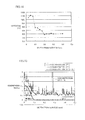
- the axes of abscissas show depths (distances) from the surfaces, and the axes of ordinates show hardness levels (Vickers hardness).
- the axes of abscissas show the depths (distances) from the surfaces and the axes of ordinates show the concentrations of carbon and nitrogen, while carbon concentrations (C concentrations), nitrogen concentrations (N concentrations) and totals (C + N concentrations) of the carbon concentrations and the nitrogen concentrations are shown in these drawings.
- a region of the sample according to Example A of the present invention within 0.5 mm in depth from the surface has sufficient hardness of at least 950 HV, with penetration of a sufficient quantity of nitrogen.
- a large number of grain boundary precipitates 90 are observed in the surface layer portion of the sample according to comparative example A out of the range of the present invention.
- a region of the sample according to comparative example A within 0.5 mm in depth from the surface has sufficient hardness of at least 950 HV with penetration of a sufficient quantity of nitrogen, similarly to the sample according to Example A of the present invention.
- a mechanical component made of steel containing at least 3.75 mass % of chromium, provided with surface layer portions of high hardness by nitriding the surface layer portions, and inhibited from formation of grain boundary precipitates can be produced.
- Example 2 of the present invention will now be described. An experiment of investigating the proper range of the heating temperature in the diffusion step of the present heat treatment method for steel was conducted. The procedure of the experiment is as follows:
- a specimen having an outer diameter ⁇ of 40 mm, an inner diameter ⁇ of 30 mm and a thickness t of 16 mm was produced by preparing and working a steel member made of AMS 6490 (AISI M50) containing at least 0.77 mass % and not more than 0.85 mass % of carbon, at least 0.01 mass % and not more than 0.25 mass % of silicon, at least 0.01 mass % and not more than 0.35 mass % of manganese, at least 0.01 mass % and not more than 0.15 mass % of nickel, at least 3.75 mass % and not more than 4.25 mass % of chromium, at least 4 mass % and not more than 4.5 mass % of molybdenum and at least 0.9 mass % and not more than 1.1 mass % of vanadium with a remainder consisting of iron and impurity.
- AMS 6490 AISI M50
- plasma nitriding was performed by controlling a discharge voltage and a discharge current in the ranges of at least 200 V and not more than 450 V and at least 1 A and not more than 5 A respectively so that the treatment temperature T 6 in the plasma nitriding was 480°C and maintaining the specimen at this temperature for one hour.
- the diffusion step was carried out on the specimen completely subjected to the plasma nitriding step by maintaining the same at 480°C for 50 hours. A hardness distribution on a surface layer portion of the specimen was measured before and after the diffusion step.
- the axis of abscissas shows heat treatment times (diffusion times), and the axis of ordinates shows hardness levels of the specimens.
- the axis of abscissas shows depths (distances) from the surfaces, and the axis of ordinates shows hardness levels.
- rhombuses show hardness levels of the specimens not yet subjected to the diffusion steps, and squares show hardness levels of the specimens subjected to the diffusion steps of maintaining the same at 480°C for 50 hours.
- the hardness of each specimen is reduced in a shorter time as the diffusion temperature is increased, while the reduction in the hardness is not more than 40 HV even if the diffusion treatment is performed for 200 hours and influence exerted by the reduction in the hardness of the matrix (hardness in a region not influenced by penetration of nitrogen resulting from the plasma nitriding) on the hardness of the surface layer portion is reduced when the diffusion temperature reaches 480°C.
- the diffusion temperature reaches 460°C
- the reduction in the hardness is not more than 25 HV even if the diffusion treatment is performed for 200 hours, and influence exerted by the reduction in the hardness of the matrix on the hardness of the surface layer portion is further reduced.
- the diffusion temperature reaches 430°C, the reduction in the hardness is not more than 10 HV even if the diffusion treatment is performed for 200 hours, and the reduction in the hardness of the matrix hardly influences the hardness of the surface layer portion.
- the actual reduction in the hardness of the matrix substantially coincides with the results of analysis shown in Fig. 16 when the diffusion step of maintaining each specimen at 480°C for 50 hours is carried out, and the results of analysis shown in Fig. 16 conceivably coincide with the results of the actual heat treatment.
- the heating temperature (diffusion temperature) in the diffusion step must be set to not more than 480°C, and is preferably set to not more than 460°C, in view of making nitrogen penetrating into steel reach a desired region while suppressing influence exerted by reduction in the hardness of the matrix on the hardness of the surface layer portion.
- the heating temperature is set to not more than 430°C, the diffusion step can be carried out while hardly exerting influence by reduction in the hardness of the matrix on the hardness of the surface layer portion.
- this heating temperature in the diffusion step is preferably further reduced in view of suppressing influence exerted by reduction in the hardness of the matrix on the hardness of the surface layer portion, this heating temperature is preferably set to at least 300°C, in order to prevent the time required for making nitrogen penetrating into steel reach the desired region from being increased beyond an allowable limit in actual production steps.
- Example 3 of the present invention will now be described.
- a sample having a structure similar to that of the present mechanical component was actually prepared in the method of producing the mechanical component according to the present invention that adopts the method of heat treatment for steel according to the present invention, and subjected to an experiment of confirming that formation of grain boundary precipitates on a surface layer portion was suppressed.
- the procedure of the experiment is as follows:
- a specimen having an outer diameter ⁇ of 40 mm, an inner diameter ⁇ of 30 mm and a thickness t of 16 mm was produced by preparing and working a steel member made of AMS 6278 (AISI M50 NiL) containing at least 0.11 mass % and not more than 0.15 mass % of carbon, at least 0.1 mass % and not more than 0.25 mass % of silicon, at least 0.15 mass % and not more than 0.35 mass % of manganese, at least 3.2 mass % and not more than 3.6 mass % of nickel, at least 4 mass % and not more than 4.25 mass % of chromium, at least 4 mass % and not more than 4.5 mass % of molybdenum and at least 1.13 mass % and not more than 1.33 mass % of vanadium with a remainder consisting of iron and impurity.
- AMS 6278 AISI M50 NiL
- a heat treatment step employing the present heat treatment method for steel described with reference to Fig. 9 in the second embodiment was carried out on this specimen.
- the temperatures T 11 , T 12 , T 13, T 14 , T 15 and T 16 and the times t 11 , t 12 , t 13 , t 14 , t 15 and t 16 were so set that the hardness of the specimen after the third tempering step was at least 58 HRC and not more than 65 HRC, while the temperatures T 17 and T 18 were both set to 430°C and the times t 17 and t 18 were set to 10 hours and 160 hours respectively.
- the discharge voltage and the discharge current were controlled in the ranges of at least 200 V and not more than 450 V and at least 1 A and not more than 5 A respectively, so that the treatment temperature T 17 in the plasma nitriding was 430°C.
- the diffusion step was so carried out that the specimen was heated in an atmosphere furnace with an atmosphere of nitrogen to adjust the total of a carbon concentration and a nitrogen concentration in the surface of the specimen being not more than 1.7 mass %.
- the specimen subjected to the present heat treatment method for steel was employed as the sample according to Example of the present invention (Example A of the present invention).
- a heat treatment step similar to the present heat treatment method for steel described in the second embodiment with reference to Fig. 9 was carried out on a similarly prepared specimen of AMS 6278 without carrying out the diffusion step, i.e., a heat treatment step departing from the scope of the present invention was carried out.
- the temperatures T 11 , T 12 , T 13 , T 14 , T 15 and T 16 and the times t 11 t 12 , t 13 , t 14 , t 15 and t 16 were so set that the hardness of the specimen after the third tempering step was at least 58 HRC and not more than 65 HRC, while the temperature T 17 was set to 480°C and the time t 17 was set to 30 hours.
- the discharge voltage and the discharge current were controlled in the ranges of at least 200 V and not more than 450 V and at least 1 A and not more than 5 A respectively, so that the treatment temperature T 17 in the plasma nitriding was 480°C.
- the specimen subjected to the aforementioned heat treatment method for steel that departs from the scope of the present invention was employed as a sample according to comparative example (comparative example A).
- Example A of the present invention and comparative example A prepared in the aforementioned manner were cut along sections perpendicular to the surfaces thereof, and these sections were polished. Further, the polished sections were etched with an etchant, and five fields of view of square regions of 150 ⁇ m on each side including the surface were thereafter randomly observed on each sample.
- a region of the sample according to Example A of the present invention within 0.5 mm in depth from the surface has sufficient hardness of at least 950 HV, with penetration of a sufficient quantity of nitrogen.
- a large number of grain boundary precipitates 90 are observed in the surface layer portion of the sample according to comparative example A out of the range of the present invention.
- a region of the sample according to comparative example A within 0.5 mm in depth from the surface has sufficient hardness of at least 950 HV with penetration of a sufficient quantity of nitrogen, similarly to the sample according to Example A of the present invention.
- Example 4 of the present invention will now be described. An experiment of investigating the proper range of the heating temperature in the diffusion step of the present heat treatment method for steel was conducted. The procedure of the experiment is as follows:
- a specimen having an outer diameter ⁇ of 40 mm, an inner diameter ⁇ of 30 mm and a thickness t of 16 mm was produced by preparing and working a steel member made of AMS 6278 (AISI M50 NiL) containing at least 0.11 mass % and not more than 0.15 mass % of carbon, at least 0.1 mass % and not more than 0.25 mass % of silicon, at least 0.15 mass % and not more than 0.35 mass % of manganese, at least 3.2 mass % and not more than 3.6 mass % of nickel, at least 4 mass % and not more than 4.25 mass % of chromium, at least 4 mass % and not more than 4.5 mass % of molybdenum and at least 1.13 mass % and not more than 1.33 mass % of vanadium with a remainder consisting of iron and impurity.
- AMS 6278 AISI M50 NiL
- plasma nitriding was performed by controlling a discharge voltage and a discharge current in the ranges of at least 200 V and not more than 450 V and at least 1 A and not more than 5 A respectively so that the treatment temperature T 17 in the plasma nitriding was 480°C and maintaining the specimen at this temperature for one hour.
- the diffusion step was carried out on the specimen completely subjected to the plasma nitriding step by maintaining the same at 480°C for 50 hours. A hardness distribution on a surface layer portion of the specimen was measured before and after the diffusion step.
- the axis of abscissas shows heat treatment times (diffusion times), and the axis of ordinates shows hardness levels of the carburized layer.
- the axis of abscissas shows depths (distances) from the surfaces, and the axis of ordinates shows hardness levels.
- rhombuses show hardness levels of the specimens not yet subjected to the diffusion steps, and squares show hardness levels of the specimens subjected to the diffusion steps of maintaining the same at 480°C for 50 hours.
- the hardness of the carburized layer of each specimen is reduced in a shorter time as the diffusion temperature is increased, while the reduction in the hardness is not more than 50 HV even if the diffusion treatment is performed for 200 hours and influence exerted by reduction in the hardness of the matrix (hardness in a region of the carburized layer not influenced by penetration of nitrogen resulting from plasma nitriding) on the hardness of the surface layer portion is reduced when the diffusion temperature reaches 480°C.
- the diffusion temperature reaches 460°C
- the reduction in the hardness is not more than 30 HV even if the diffusion treatment is performed for 200 hours, and influence exerted by the reduction in the hardness of the matrix on the hardness of the surface layer portion is further reduced.
- the diffusion temperature reaches 430°C, the reduction in the hardness is not more than 10 HV even if the diffusion treatment is performed for 200 hours, and the reduction in the hardness of the matrix hardly influences the hardness of the surface layer portion.
- the actual reduction in the hardness of the matrix substantially coincides with the results of analysis shown in Fig. 24 when the diffusion step of maintaining each specimen at 480°C for 50 hours is carried out, and the results of analysis shown in Fig. 24 conceivably coincide with the results of the actual heat treatment.
- the heating temperature (diffusion temperature) in the diffusion step must be set to not more than 480°C, and is preferably set to not more than 460°C, in view of making nitrogen penetrating into steel reach a desired region while suppressing influence exerted by reduction in the hardness of the matrix on the hardness of the surface layer portion.
- the heating temperature is set to not more than 430°C, the diffusion step can be carried out while hardly exerting influence by reduction in the hardness of the matrix on the hardness of the surface layer portion.
- this heating temperature in the diffusion step is preferably further reduced in view of suppressing influence exerted by reduction in the hardness of the matrix on the hardness of the surface layer portion, this heating temperature is preferably set to at least 300°C, in order to prevent the time required for making nitrogen penetrating into steel reach the desired region from being increased beyond an allowable limit in actual production steps.
- the present invention provides a method of heat treatment for steel, a method of producing a mechanical component, and the mechanical component that are advantageously applicable in particular to methods of heat treatment for steel that include the step of nitriding an object to be treated that is formed of steel containing at least 3.75 mass % of chromium, mechanical components formed of steel containing at least 3.75 mass % of chromium and having a surface layer portion nitrided, and methods of producing the mechanical components.
Landscapes
- Chemical & Material Sciences (AREA)
- Engineering & Computer Science (AREA)
- Materials Engineering (AREA)
- Mechanical Engineering (AREA)
- Metallurgy (AREA)
- Organic Chemistry (AREA)
- Thermal Sciences (AREA)
- Crystallography & Structural Chemistry (AREA)
- Physics & Mathematics (AREA)
- Chemical Kinetics & Catalysis (AREA)
- Heat Treatment Of Articles (AREA)
- Solid-Phase Diffusion Into Metallic Material Surfaces (AREA)
- Rolling Contact Bearings (AREA)
Applications Claiming Priority (3)
| Application Number | Priority Date | Filing Date | Title |
|---|---|---|---|
| JP2007295892A JP5429729B2 (ja) | 2007-11-14 | 2007-11-14 | 機械部品の製造方法および機械部品 |
| JP2007310368A JP5429730B2 (ja) | 2007-11-30 | 2007-11-30 | 機械部品の製造方法および機械部品 |
| EP08850887.4A EP2221389B1 (fr) | 2007-11-14 | 2008-11-12 | Procédé de traitement thermique de l'acier et procédé de production d'une pièce de machine |
Related Parent Applications (3)
| Application Number | Title | Priority Date | Filing Date |
|---|---|---|---|
| EP08850887.4A Division-Into EP2221389B1 (fr) | 2007-11-14 | 2008-11-12 | Procédé de traitement thermique de l'acier et procédé de production d'une pièce de machine |
| EP08850887.4A Division EP2221389B1 (fr) | 2007-11-14 | 2008-11-12 | Procédé de traitement thermique de l'acier et procédé de production d'une pièce de machine |
| EP08850887.4 Division | 2008-11-12 |
Publications (3)
| Publication Number | Publication Date |
|---|---|
| EP2405028A2 true EP2405028A2 (fr) | 2012-01-11 |
| EP2405028A3 EP2405028A3 (fr) | 2012-02-08 |
| EP2405028B1 EP2405028B1 (fr) | 2016-03-30 |
Family
ID=40638758
Family Applications (2)
| Application Number | Title | Priority Date | Filing Date |
|---|---|---|---|
| EP11180367.2A Not-in-force EP2405028B1 (fr) | 2007-11-14 | 2008-11-12 | Procédé pour le traitement thermique de l'acier et procédé de production d'un composant mécanique |
| EP08850887.4A Not-in-force EP2221389B1 (fr) | 2007-11-14 | 2008-11-12 | Procédé de traitement thermique de l'acier et procédé de production d'une pièce de machine |
Family Applications After (1)
| Application Number | Title | Priority Date | Filing Date |
|---|---|---|---|
| EP08850887.4A Not-in-force EP2221389B1 (fr) | 2007-11-14 | 2008-11-12 | Procédé de traitement thermique de l'acier et procédé de production d'une pièce de machine |
Country Status (3)
| Country | Link |
|---|---|
| EP (2) | EP2405028B1 (fr) |
| CN (2) | CN102352479B (fr) |
| WO (1) | WO2009063909A1 (fr) |
Cited By (2)
| Publication number | Priority date | Publication date | Assignee | Title |
|---|---|---|---|---|
| EP2899292A4 (fr) * | 2012-09-19 | 2016-04-27 | Ntn Toyo Bearing Co Ltd | Procédé de production d'une pièce de machine |
| WO2022231745A1 (fr) * | 2021-04-30 | 2022-11-03 | Caterpillar Inc. | Composants d'acier carburés à haute résistance |
Families Citing this family (7)
| Publication number | Priority date | Publication date | Assignee | Title |
|---|---|---|---|---|
| JP5927018B2 (ja) * | 2011-04-26 | 2016-05-25 | Ntn株式会社 | 機械部品の製造方法 |
| DE102012205242A1 (de) * | 2012-03-30 | 2013-10-02 | Schaeffler Technologies AG & Co. KG | Wälzlagerbauteil |
| CN103014601A (zh) * | 2012-12-09 | 2013-04-03 | 常州大学 | 一种奥氏体不锈钢离子氮化催渗工艺 |
| CN104551577B (zh) * | 2015-01-30 | 2016-09-21 | 温州神一微型轴有限公司 | 一种微型轴的制造方法 |
| CN104694725B (zh) * | 2015-03-13 | 2017-03-15 | 山东大学 | 一种超高强度超耐磨链条的制造工艺 |
| DE112016003760T5 (de) * | 2015-08-17 | 2018-05-03 | Ntn Corporation | Gleitelement und Verfahren zu seiner Herstellung |
| JP7078220B2 (ja) * | 2017-02-22 | 2022-05-31 | 学校法人トヨタ学園 | 金属製品の製造方法 |
Citations (3)
| Publication number | Priority date | Publication date | Assignee | Title |
|---|---|---|---|---|
| JPH0257675A (ja) | 1988-08-23 | 1990-02-27 | Daido Steel Co Ltd | プラズマ浸炭窒化炉におけるガスの送入方法 |
| JPH07118826A (ja) | 1993-10-20 | 1995-05-09 | Limes:Kk | 金属部材のイオン窒化方法 |
| JPH093646A (ja) | 1995-06-13 | 1997-01-07 | Ipsen Ind Internatl Gmbh | プラズマ中において部材を熱処理する際の電流密度の制御方法及び装置 |
Family Cites Families (8)
| Publication number | Priority date | Publication date | Assignee | Title |
|---|---|---|---|---|
| JP2001192861A (ja) * | 1999-12-28 | 2001-07-17 | Hitachi Ltd | 表面処理方法及び表面処理装置 |
| JP2003148488A (ja) * | 2001-11-08 | 2003-05-21 | Nsk Ltd | 転動装置及びその製造方法 |
| JP2003148485A (ja) * | 2001-11-12 | 2003-05-21 | Ntn Corp | 転がり軸受 |
| JP3961390B2 (ja) * | 2002-10-04 | 2007-08-22 | エア・ウォーター株式会社 | 耐摩耗性にすぐれた表面炭窒化ステンレス鋼部品およびその製造方法 |
| US6966954B2 (en) * | 2002-10-24 | 2005-11-22 | General Electric Comany | Spall propagation properties of case-hardened M50 and M50NiL bearings |
| US8070364B2 (en) * | 2004-08-04 | 2011-12-06 | Schaeffler Kg | Rolling bearing of ceramic and steel engaging parts |
| EP1831408A4 (fr) * | 2004-12-23 | 2010-07-21 | United Technologies Corp | Composition et processus permettant de renforcer les proprietes de composants ferreux |
| JP2007040230A (ja) * | 2005-08-04 | 2007-02-15 | Aisin Seiki Co Ltd | ベーン、ベーンの製造方法、弁開閉時期制御装置 |
-
2008
- 2008-11-12 WO PCT/JP2008/070596 patent/WO2009063909A1/fr active Application Filing
- 2008-11-12 EP EP11180367.2A patent/EP2405028B1/fr not_active Not-in-force
- 2008-11-12 CN CN2011102857059A patent/CN102352479B/zh not_active Expired - Fee Related
- 2008-11-12 EP EP08850887.4A patent/EP2221389B1/fr not_active Not-in-force
- 2008-11-12 CN CN2008801164726A patent/CN101855370B/zh not_active Expired - Fee Related
Patent Citations (3)
| Publication number | Priority date | Publication date | Assignee | Title |
|---|---|---|---|---|
| JPH0257675A (ja) | 1988-08-23 | 1990-02-27 | Daido Steel Co Ltd | プラズマ浸炭窒化炉におけるガスの送入方法 |
| JPH07118826A (ja) | 1993-10-20 | 1995-05-09 | Limes:Kk | 金属部材のイオン窒化方法 |
| JPH093646A (ja) | 1995-06-13 | 1997-01-07 | Ipsen Ind Internatl Gmbh | プラズマ中において部材を熱処理する際の電流密度の制御方法及び装置 |
Cited By (2)
| Publication number | Priority date | Publication date | Assignee | Title |
|---|---|---|---|---|
| EP2899292A4 (fr) * | 2012-09-19 | 2016-04-27 | Ntn Toyo Bearing Co Ltd | Procédé de production d'une pièce de machine |
| WO2022231745A1 (fr) * | 2021-04-30 | 2022-11-03 | Caterpillar Inc. | Composants d'acier carburés à haute résistance |
Also Published As
| Publication number | Publication date |
|---|---|
| WO2009063909A1 (fr) | 2009-05-22 |
| CN101855370B (zh) | 2012-09-19 |
| EP2221389A4 (fr) | 2012-02-08 |
| EP2221389B1 (fr) | 2018-01-03 |
| CN101855370A (zh) | 2010-10-06 |
| CN102352479B (zh) | 2013-11-06 |
| CN102352479A (zh) | 2012-02-15 |
| EP2221389A1 (fr) | 2010-08-25 |
| EP2405028B1 (fr) | 2016-03-30 |
| EP2405028A3 (fr) | 2012-02-08 |
Similar Documents
| Publication | Publication Date | Title |
|---|---|---|
| EP2405028B1 (fr) | Procédé pour le traitement thermique de l'acier et procédé de production d'un composant mécanique | |
| EP2397567B1 (fr) | Composant de machine et roulement à rouleaux | |
| JP2009052119A (ja) | 鋼の熱処理方法、機械部品の製造方法および機械部品 | |
| EP2888379B1 (fr) | Procédé de traitement thermique d'une pièce d'acier | |
| EP2888377B1 (fr) | Procédé de traitement thermique d'une pièce d'acier et pièce d'acier | |
| US20170081738A1 (en) | Method & metal component | |
| JP2010285642A (ja) | 鋼の熱処理方法、機械部品の製造方法および機械部品 | |
| JP5397927B2 (ja) | 機械部品 | |
| JP5397928B2 (ja) | 機械部品 | |
| JP2010024492A (ja) | 鋼の熱処理方法、機械部品の製造方法および機械部品 | |
| JP5429730B2 (ja) | 機械部品の製造方法および機械部品 | |
| JP5429729B2 (ja) | 機械部品の製造方法および機械部品 | |
| JP2017043800A (ja) | 熱処理方法、及び転がり軸受用部材 | |
| JP2009235446A (ja) | 鋼の熱処理方法、機械部品の製造方法、機械部品および転がり軸受 | |
| JP2009235445A (ja) | 鋼の熱処理方法、機械部品の製造方法、機械部品および転がり軸受 | |
| JP2009235444A (ja) | 鋼の熱処理方法、機械部品の製造方法、機械部品および転がり軸受 | |
| JP6658143B2 (ja) | 転がり摺動部材及び転がり軸受 | |
| JP2017066498A (ja) | 鋼の熱処理方法および鋼部材 |
Legal Events
| Date | Code | Title | Description |
|---|---|---|---|
| REG | Reference to a national code |
Ref country code: DE Ref legal event code: R079 Ref document number: 602008043255 Country of ref document: DE Free format text: PREVIOUS MAIN CLASS: C23C0008380000 Ipc: C21D0001060000 |
|
| PUAL | Search report despatched |
Free format text: ORIGINAL CODE: 0009013 |
|
| 17P | Request for examination filed |
Effective date: 20110907 |
|
| AC | Divisional application: reference to earlier application |
Ref document number: 2221389 Country of ref document: EP Kind code of ref document: P |
|
| AK | Designated contracting states |
Kind code of ref document: A2 Designated state(s): AT BE BG CH CY CZ DE DK EE ES FI FR GB GR HR HU IE IS IT LI LT LU LV MC MT NL NO PL PT RO SE SI SK TR |
|
| PUAI | Public reference made under article 153(3) epc to a published international application that has entered the european phase |
Free format text: ORIGINAL CODE: 0009012 |
|
| AK | Designated contracting states |
Kind code of ref document: A3 Designated state(s): AT BE BG CH CY CZ DE DK EE ES FI FR GB GR HR HU IE IS IT LI LT LU LV MC MT NL NO PL PT RO SE SI SK TR |
|
| RIC1 | Information provided on ipc code assigned before grant |
Ipc: C23C 8/26 20060101ALI20120104BHEP Ipc: C21D 9/40 20060101ALI20120104BHEP Ipc: C21D 1/78 20060101ALI20120104BHEP Ipc: C23C 8/22 20060101ALI20120104BHEP Ipc: C22C 38/00 20060101ALI20120104BHEP Ipc: C23C 8/38 20060101ALI20120104BHEP Ipc: C22C 38/46 20060101ALI20120104BHEP Ipc: C21D 1/18 20060101ALI20120104BHEP Ipc: C21D 6/00 20060101ALI20120104BHEP Ipc: C21D 1/06 20060101AFI20120104BHEP |
|
| 17Q | First examination report despatched |
Effective date: 20130109 |
|
| GRAP | Despatch of communication of intention to grant a patent |
Free format text: ORIGINAL CODE: EPIDOSNIGR1 |
|
| INTG | Intention to grant announced |
Effective date: 20150930 |
|
| GRAS | Grant fee paid |
Free format text: ORIGINAL CODE: EPIDOSNIGR3 |
|
| GRAA | (expected) grant |
Free format text: ORIGINAL CODE: 0009210 |
|
| AC | Divisional application: reference to earlier application |
Ref document number: 2221389 Country of ref document: EP Kind code of ref document: P |
|
| AK | Designated contracting states |
Kind code of ref document: B1 Designated state(s): AT BE BG CH CY CZ DE DK EE ES FI FR GB GR HR HU IE IS IT LI LT LU LV MC MT NL NO PL PT RO SE SI SK TR |
|
| REG | Reference to a national code |
Ref country code: GB Ref legal event code: FG4D |
|
| REG | Reference to a national code |
Ref country code: CH Ref legal event code: EP |
|
| REG | Reference to a national code |
Ref country code: AT Ref legal event code: REF Ref document number: 785470 Country of ref document: AT Kind code of ref document: T Effective date: 20160415 |
|
| REG | Reference to a national code |
Ref country code: IE Ref legal event code: FG4D |
|
| REG | Reference to a national code |
Ref country code: DE Ref legal event code: R096 Ref document number: 602008043255 Country of ref document: DE |
|
| REG | Reference to a national code |
Ref country code: LT Ref legal event code: MG4D |
|
| PG25 | Lapsed in a contracting state [announced via postgrant information from national office to epo] |
Ref country code: GR Free format text: LAPSE BECAUSE OF FAILURE TO SUBMIT A TRANSLATION OF THE DESCRIPTION OR TO PAY THE FEE WITHIN THE PRESCRIBED TIME-LIMIT Effective date: 20160701 Ref country code: NO Free format text: LAPSE BECAUSE OF FAILURE TO SUBMIT A TRANSLATION OF THE DESCRIPTION OR TO PAY THE FEE WITHIN THE PRESCRIBED TIME-LIMIT Effective date: 20160630 Ref country code: FI Free format text: LAPSE BECAUSE OF FAILURE TO SUBMIT A TRANSLATION OF THE DESCRIPTION OR TO PAY THE FEE WITHIN THE PRESCRIBED TIME-LIMIT Effective date: 20160330 Ref country code: HR Free format text: LAPSE BECAUSE OF FAILURE TO SUBMIT A TRANSLATION OF THE DESCRIPTION OR TO PAY THE FEE WITHIN THE PRESCRIBED TIME-LIMIT Effective date: 20160330 |
|
| REG | Reference to a national code |
Ref country code: NL Ref legal event code: MP Effective date: 20160330 |
|
| REG | Reference to a national code |
Ref country code: AT Ref legal event code: MK05 Ref document number: 785470 Country of ref document: AT Kind code of ref document: T Effective date: 20160330 |
|
| PG25 | Lapsed in a contracting state [announced via postgrant information from national office to epo] |
Ref country code: LV Free format text: LAPSE BECAUSE OF FAILURE TO SUBMIT A TRANSLATION OF THE DESCRIPTION OR TO PAY THE FEE WITHIN THE PRESCRIBED TIME-LIMIT Effective date: 20160330 Ref country code: SE Free format text: LAPSE BECAUSE OF FAILURE TO SUBMIT A TRANSLATION OF THE DESCRIPTION OR TO PAY THE FEE WITHIN THE PRESCRIBED TIME-LIMIT Effective date: 20160330 Ref country code: LT Free format text: LAPSE BECAUSE OF FAILURE TO SUBMIT A TRANSLATION OF THE DESCRIPTION OR TO PAY THE FEE WITHIN THE PRESCRIBED TIME-LIMIT Effective date: 20160330 |
|
| PG25 | Lapsed in a contracting state [announced via postgrant information from national office to epo] |
Ref country code: NL Free format text: LAPSE BECAUSE OF FAILURE TO SUBMIT A TRANSLATION OF THE DESCRIPTION OR TO PAY THE FEE WITHIN THE PRESCRIBED TIME-LIMIT Effective date: 20160330 |
|
| PG25 | Lapsed in a contracting state [announced via postgrant information from national office to epo] |
Ref country code: IS Free format text: LAPSE BECAUSE OF FAILURE TO SUBMIT A TRANSLATION OF THE DESCRIPTION OR TO PAY THE FEE WITHIN THE PRESCRIBED TIME-LIMIT Effective date: 20160730 Ref country code: PL Free format text: LAPSE BECAUSE OF FAILURE TO SUBMIT A TRANSLATION OF THE DESCRIPTION OR TO PAY THE FEE WITHIN THE PRESCRIBED TIME-LIMIT Effective date: 20160330 Ref country code: EE Free format text: LAPSE BECAUSE OF FAILURE TO SUBMIT A TRANSLATION OF THE DESCRIPTION OR TO PAY THE FEE WITHIN THE PRESCRIBED TIME-LIMIT Effective date: 20160330 |
|
| REG | Reference to a national code |
Ref country code: FR Ref legal event code: PLFP Year of fee payment: 9 |
|
| PG25 | Lapsed in a contracting state [announced via postgrant information from national office to epo] |
Ref country code: ES Free format text: LAPSE BECAUSE OF FAILURE TO SUBMIT A TRANSLATION OF THE DESCRIPTION OR TO PAY THE FEE WITHIN THE PRESCRIBED TIME-LIMIT Effective date: 20160330 Ref country code: PT Free format text: LAPSE BECAUSE OF FAILURE TO SUBMIT A TRANSLATION OF THE DESCRIPTION OR TO PAY THE FEE WITHIN THE PRESCRIBED TIME-LIMIT Effective date: 20160801 Ref country code: RO Free format text: LAPSE BECAUSE OF FAILURE TO SUBMIT A TRANSLATION OF THE DESCRIPTION OR TO PAY THE FEE WITHIN THE PRESCRIBED TIME-LIMIT Effective date: 20160330 Ref country code: SK Free format text: LAPSE BECAUSE OF FAILURE TO SUBMIT A TRANSLATION OF THE DESCRIPTION OR TO PAY THE FEE WITHIN THE PRESCRIBED TIME-LIMIT Effective date: 20160330 Ref country code: CZ Free format text: LAPSE BECAUSE OF FAILURE TO SUBMIT A TRANSLATION OF THE DESCRIPTION OR TO PAY THE FEE WITHIN THE PRESCRIBED TIME-LIMIT Effective date: 20160330 Ref country code: AT Free format text: LAPSE BECAUSE OF FAILURE TO SUBMIT A TRANSLATION OF THE DESCRIPTION OR TO PAY THE FEE WITHIN THE PRESCRIBED TIME-LIMIT Effective date: 20160330 |
|
| PG25 | Lapsed in a contracting state [announced via postgrant information from national office to epo] |
Ref country code: BE Free format text: LAPSE BECAUSE OF FAILURE TO SUBMIT A TRANSLATION OF THE DESCRIPTION OR TO PAY THE FEE WITHIN THE PRESCRIBED TIME-LIMIT Effective date: 20160330 Ref country code: IT Free format text: LAPSE BECAUSE OF FAILURE TO SUBMIT A TRANSLATION OF THE DESCRIPTION OR TO PAY THE FEE WITHIN THE PRESCRIBED TIME-LIMIT Effective date: 20160330 |
|
| REG | Reference to a national code |
Ref country code: DE Ref legal event code: R097 Ref document number: 602008043255 Country of ref document: DE |
|
| PG25 | Lapsed in a contracting state [announced via postgrant information from national office to epo] |
Ref country code: DK Free format text: LAPSE BECAUSE OF FAILURE TO SUBMIT A TRANSLATION OF THE DESCRIPTION OR TO PAY THE FEE WITHIN THE PRESCRIBED TIME-LIMIT Effective date: 20160330 |
|
| PLBE | No opposition filed within time limit |
Free format text: ORIGINAL CODE: 0009261 |
|
| STAA | Information on the status of an ep patent application or granted ep patent |
Free format text: STATUS: NO OPPOSITION FILED WITHIN TIME LIMIT |
|
| 26N | No opposition filed |
Effective date: 20170103 |
|
| PG25 | Lapsed in a contracting state [announced via postgrant information from national office to epo] |
Ref country code: SI Free format text: LAPSE BECAUSE OF FAILURE TO SUBMIT A TRANSLATION OF THE DESCRIPTION OR TO PAY THE FEE WITHIN THE PRESCRIBED TIME-LIMIT Effective date: 20160330 |
|
| REG | Reference to a national code |
Ref country code: DE Ref legal event code: R119 Ref document number: 602008043255 Country of ref document: DE |
|
| REG | Reference to a national code |
Ref country code: CH Ref legal event code: PL |
|
| GBPC | Gb: european patent ceased through non-payment of renewal fee |
Effective date: 20161112 |
|
| PG25 | Lapsed in a contracting state [announced via postgrant information from national office to epo] |
Ref country code: LI Free format text: LAPSE BECAUSE OF NON-PAYMENT OF DUE FEES Effective date: 20161130 Ref country code: CH Free format text: LAPSE BECAUSE OF NON-PAYMENT OF DUE FEES Effective date: 20161130 |
|
| REG | Reference to a national code |
Ref country code: IE Ref legal event code: MM4A |
|
| PG25 | Lapsed in a contracting state [announced via postgrant information from national office to epo] |
Ref country code: LU Free format text: LAPSE BECAUSE OF NON-PAYMENT OF DUE FEES Effective date: 20161130 |
|
| REG | Reference to a national code |
Ref country code: FR Ref legal event code: PLFP Year of fee payment: 10 |
|
| PG25 | Lapsed in a contracting state [announced via postgrant information from national office to epo] |
Ref country code: IE Free format text: LAPSE BECAUSE OF NON-PAYMENT OF DUE FEES Effective date: 20161112 Ref country code: GB Free format text: LAPSE BECAUSE OF NON-PAYMENT OF DUE FEES Effective date: 20161112 Ref country code: DE Free format text: LAPSE BECAUSE OF NON-PAYMENT OF DUE FEES Effective date: 20170601 |
|
| PG25 | Lapsed in a contracting state [announced via postgrant information from national office to epo] |
Ref country code: HU Free format text: LAPSE BECAUSE OF FAILURE TO SUBMIT A TRANSLATION OF THE DESCRIPTION OR TO PAY THE FEE WITHIN THE PRESCRIBED TIME-LIMIT; INVALID AB INITIO Effective date: 20081112 Ref country code: CY Free format text: LAPSE BECAUSE OF FAILURE TO SUBMIT A TRANSLATION OF THE DESCRIPTION OR TO PAY THE FEE WITHIN THE PRESCRIBED TIME-LIMIT Effective date: 20160330 |
|
| PG25 | Lapsed in a contracting state [announced via postgrant information from national office to epo] |
Ref country code: TR Free format text: LAPSE BECAUSE OF FAILURE TO SUBMIT A TRANSLATION OF THE DESCRIPTION OR TO PAY THE FEE WITHIN THE PRESCRIBED TIME-LIMIT Effective date: 20160330 Ref country code: MC Free format text: LAPSE BECAUSE OF FAILURE TO SUBMIT A TRANSLATION OF THE DESCRIPTION OR TO PAY THE FEE WITHIN THE PRESCRIBED TIME-LIMIT Effective date: 20160330 |
|
| PG25 | Lapsed in a contracting state [announced via postgrant information from national office to epo] |
Ref country code: BG Free format text: LAPSE BECAUSE OF FAILURE TO SUBMIT A TRANSLATION OF THE DESCRIPTION OR TO PAY THE FEE WITHIN THE PRESCRIBED TIME-LIMIT Effective date: 20160330 |
|
| PG25 | Lapsed in a contracting state [announced via postgrant information from national office to epo] |
Ref country code: MT Free format text: LAPSE BECAUSE OF NON-PAYMENT OF DUE FEES Effective date: 20161112 |
|
| REG | Reference to a national code |
Ref country code: FR Ref legal event code: PLFP Year of fee payment: 11 |
|
| PGFP | Annual fee paid to national office [announced via postgrant information from national office to epo] |
Ref country code: FR Payment date: 20211018 Year of fee payment: 14 |
|
| PG25 | Lapsed in a contracting state [announced via postgrant information from national office to epo] |
Ref country code: FR Free format text: LAPSE BECAUSE OF NON-PAYMENT OF DUE FEES Effective date: 20221130 |